LP3947 USB/AC Adaptor, Single Cell Li-Ion Battery ... - Farnell
LP3947 USB/AC Adaptor, Single Cell Li-Ion Battery ... - Farnell
LP3947 USB/AC Adaptor, Single Cell Li-Ion Battery ... - Farnell

Create successful ePaper yourself
Turn your PDF publications into a flip-book with our unique Google optimized e-Paper software.
<strong>LP3947</strong><br />
Electrical Characteristics, I 2 C Interface (Continued)<br />
Unless otherwise noted, VCHG-IN =VDD = 5V, VBATT = 4V. Typical values and limits appearing in normal type apply for TJ =<br />
25˚C. <strong>Li</strong>mits appearing in boldface type apply over the entire junction temperature range for operation, TJ = −40˚C to +125˚C.<br />
(Notes 7, 8, 9)<br />
Symbol Parameter Conditions Typ<br />
Min<br />
<strong>Li</strong>mit<br />
Max<br />
Units<br />
tSU Set-Up Time Repeated START<br />
Condition<br />
(Note 8)<br />
0.6 µs<br />
tDATA-HOLD Data Hold Time (Note 8) 300 ns<br />
tDATA-SU Data Set-Up Time (Note 8) 100 ns<br />
tSU Set-Up Time for STOP Condition (Note 8) 0.6 µs<br />
tTRANS Maximum Pulse Width of Spikes that (Note 8)<br />
must be Suppressed by the Input<br />
Filter of both DATA & CLK Signals.<br />
50 ns<br />
Note 1: Absolute Maximum Ratings are limits beyond which damage to the device may occur. Operating Ratings are conditions under which operation of the device<br />
is guaranteed. Operating Ratings do not imply guaranteed performance limits. For guaranteed performance limits and associated test conditions, see the Electrical<br />
Characteristics tables.<br />
Note 2: All voltages are with respect to the potential at the GND pin.<br />
Note 3: Caution must be taken to avoid raising pins EN and VT 0.3V higher than VCHG-IN and raising pins ISEL, MODE, SCL and SDA 0.3V higher than VBATT. Note 4: The Absolute Maximum power dissipation depends on the ambient temperature and can be calculated using the formula<br />
P=(T J –T A)θ JA, (1)<br />
where TJ is the junction temperature, TA is the ambient temperature, and θJA is the junction-to-ambient thermal resistance. The 1.89W rating appearing under<br />
Absolute Maximum Ratings results from substituting the Absolute Maximum junction temperature, 150˚C, for TJ, 80˚C for TA, and 37˚C/W for θJA. More power can<br />
be dissipated safely at ambient temperatures below 80˚C. Less power can be dissipated safely at ambient temperatures above 80˚C. The Absolute Maximum power<br />
dissipation can be increased by 27 mW for each degree below 80˚C, and it must be de-rated by 27 mW for each degree above 80˚C.<br />
Note 5: The human-body model is used. The human-body model is 100 pF discharged through 1.5 kΩ.<br />
Note 6: <strong>Li</strong>ke the Absolute Maximum power dissipation, the maximum power dissipation for operation depends on the ambient temperature. The 1.21W rating<br />
appearing under Operating Ratings results from substituting the maximum junction temperature for operation, 125˚C, for TJ, 80˚C for TA, and 37˚C/W for θJA into<br />
(1) above. More power can be dissipated at ambient temperatures below 80˚C. Less power can be dissipated at ambient temperatures above 80˚C. The maximum<br />
power dissipation for operation can be increased by 27 mW for each degree below 80˚C, and it must be de-rated by 27 mW for each degree above 80˚C.<br />
Note 7: All limits are guaranteed. All electrical characteristics having room-temperature limits are tested during production with TJ = 25˚C. All hot and cold limits are<br />
guaranteed by correlating the electrical characteristics to process and temperature variations and applying statistical process control.<br />
Note 8: Guaranteed by design.<br />
Note 9: <strong>LP3947</strong> is not intended as a <strong>Li</strong>-<strong>Ion</strong> battery protection device, any battery used in this application should have an adequate internal protection.<br />
Note 10: The ±10 mA limits apply to all charge currents from 100 mA to 450 mA, to 0.1C End Of Charge (EOC). The limits increase proportionally with higher EOC<br />
points. For example, at 0.2C, the End Of Charge current accuracy becomes ±20 mA.<br />
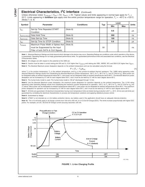
FIGURE 1. <strong>Li</strong>-<strong>Ion</strong> Charging Profile<br />
www.national.com 6<br />
20111004