data sheet
data sheet
data sheet

Create successful ePaper yourself
Turn your PDF publications into a flip-book with our unique Google optimized e-Paper software.
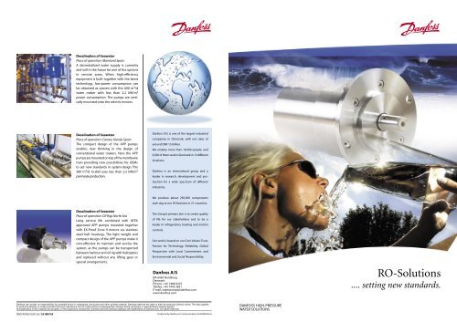
Desalination of Seawater<br />
Place of operation: Mainland Spain<br />
A decentralized water supply is currently<br />
and will in the future be one of the options<br />
in remote areas. When high-efficiency<br />
equipment is built together with the latest<br />
technology, low-power consumption can<br />
be obtained as proven with this 600 m 3 /d<br />
water maker with less than 2.2 kW/m 3<br />
power consumption. The pumps are vertically<br />
mounted onto the electric motors .<br />
Desalination of Seawater<br />
Place of operation: Canary Islands Spain<br />
The compact design of the APP pumps<br />
enables new thinking in the design of<br />
conventional water makers. Here the APP<br />
pumps are mounted on top of the membrane<br />
train providing new possibilities for OEMs<br />
to set new standards in system design. This<br />
300 m 3 /d ro-skid uses less than 2.3 kW/m 3<br />
permeate production.<br />
Danfoss A/S is one of the largest industrial<br />
companies in Denmark, with net sales of<br />
around DKK 15 billion.<br />
We employ more than 18,500 people, and<br />
6,500 of them work in Denmark in 15 different<br />
locations.<br />
Danfoss is an international group and a<br />
leader in research, development and production<br />
for a wide spectrum of different<br />
industries.<br />
Desalination of Seawater<br />
Place of operation: Oil Rigs North Sea<br />
Long service life combined with ATEX<br />
approved APP pumps mounted together<br />
with EX-Proof Zone II motors via stainless<br />
steel bell housings. The light weight and<br />
compact design of the APP pumps make it<br />
cost-effective to maintain and service the<br />
system, as the pumps can be transported<br />
between harbour and oil rig with helicopters<br />
and replaced without any lifting gear or<br />
special arrangements.<br />
We produce about 250,000 components<br />
each day at our 59 factories in 21 countries.<br />
The Group’s primary aim is to create quality<br />
of life for our stakeholders and to be a<br />
leader in refrigeration, heating and motion<br />
controls.<br />
Our work is based on our Core Values: Trust,<br />
Passion for Technology, Reliability, Global<br />
Perspective with Local Commitment and<br />
Environmental and Social Responsibility.<br />
Danfoss A/S<br />
DK-6430 Nordborg<br />
Denmark<br />
Phone: +45 7488 4325<br />
Telefax: +45 7445 3831<br />
E-mail: waterpumps@danfoss.com<br />
www.danfoss.com<br />
RO-Solutions<br />
.... setting new standards.<br />
DKCFN.PB.010.B1.02 / 521B0734<br />
Produced by Danfoss G1 Communication 04.09.MR.JN.na<br />
DANFOSS HIGH-PRESSURE<br />
WATER SOLUTIONS
The Natural Choice<br />
APP 0.6-1.0 specifications<br />
Metric measure US measure<br />
Flow APP 0.6 10 l/min 2.6 GPM<br />
APP 1.0 17 l/min 4.5 GPM<br />
Discharge pressure 10 to 80 bar 140-1150 psi<br />
Inlet pressure Flodded to 7 bar Flodded to 100 psi<br />
Pump rpm 1) 700-3000 rpm 700-3000 rpm<br />
Horse power APP 0.6 1.5 kW 2.0 HP<br />
At 80 bar APP 1.0 2.2 kW 3.2 HP<br />
Weight 4.4 kg 9.7 lbs<br />
Inlet port 1 ⁄ 2 ” BSP 1 ⁄ 2 ” BSP<br />
Outlet port 1 ⁄ 2 ” BSP 1 ⁄ 2 ” BSP<br />
APP 1.8-2.2 specification<br />
Metric measure US measure<br />
Flow APP 1.8 28 l/min 7.3 GPM<br />
APP 2.2 35 l/min 9.2 GPM<br />
Discharge pressure 10 to 80 bar 140-1150 psi<br />
Inlet pressure Flodded to 7 bar Flodded to 100 psi<br />
Pump rpm 1) 700-3000 rpm 700-3000 rpm<br />
Horse power APP 1.8 4.2 kW 5.7 HP<br />
At 80 bar APP 2.2 5.5 kW 7.0 HP<br />
Weight 7.7 kg 17 lbs<br />
Inlet port 3 ⁄ 4 ” BSP 3 ⁄ 4 ” BSP<br />
Outlet port 1 ⁄ 2 ” BSP 1 ⁄ 2 ” BSP<br />
APP 5.1-10.2 specifications:<br />
Metric measure US measure<br />
Flow APP 5.1 85 l/min 22.45 GPM<br />
APP 6.5 108 l/min 28.1 GPM<br />
APP 7.2 120 l/min 31.7 GPM<br />
APP 8.2 136 l/min 35.4 GPM<br />
APP 10.2 170 l/min 44.9 GPM<br />
Discharge pressure 10-80 bar 140-1150 psi<br />
Inlet pressure Flodded to 7 bar Flodded to 7 bar<br />
Pump rpm 700-1800 rpm 700-1800 rpm<br />
Horse power APP 5.1 13.3 kW 17.9 HP<br />
At 80 bar APP 6.5 15 kW 20 HP<br />
APP 7.2 18.6 kW 25 HP<br />
APP 8.2 19 kW 25.5 HP<br />
APP 10.2 26.7 kW 35.9 HP<br />
Weight 32 kg 70 lbs<br />
Inlet port 2) 1 1 ⁄ 2 ” VIC. 1 1 ⁄ 2 ” VIC.<br />
Outlet port 2) 1 1 ⁄ 2 ” VIC. 1 1 ⁄ 2 ” VIC.<br />
1) Higher speed available. Please contact the Sales Organisation.<br />
2) Other types of connections available on request.<br />
Common material specifications<br />
• All wetted parts : Superdublex, polymer, ceramic<br />
• All external parts: Superdublex, 316 SS, plastic<br />
The Axial Piston Pump (APP) is a positive displacement pump design<br />
originating from oil hydraulics and subsequently redesigned by<br />
Danfoss during the last 15 years, to pump tap and seawater. Tens of<br />
thousands of pumps are in operation worldwide proving the<br />
pumps to be among the most cost-effective and reliable pumps for<br />
membrane applications, both as main high-pressure pumps but<br />
also for recovering energy as reversing pumps (motors) in the reject<br />
line. The pumps are made in exotic materials incorporating Duplex<br />
and Superduplex materials as standard.<br />
Danfoss A/S RO-Solutions offers not only High-Pressure Pumps but<br />
also Frequency Inverters, Soft Starters, Valves, Pressure Transmitters<br />
and all kinds of “around-the-pump” accessories, since one of our<br />
goals is to facilitate supply chain optimisation for our customers.<br />
If your business is among the below mentioned applications:<br />
• Seawater Reverse Osmosis<br />
• Brackish Water Reverse Osmosis<br />
• Nanofiltration, ultrafiltration, microfiltration<br />
• Or even pump and measure low-viscosity corrosive fluids<br />
prefiltered down to 10 micron absolute<br />
... have a look on our homepage www.nessie.danfoss.com/rosolution<br />
With APP pumps from Danfoss you get the following<br />
benefits<br />
Low energy consumption<br />
Total efficiencies up to 95 percent – among the most efficient in the<br />
market.<br />
Long service life<br />
Danfoss guarantees service free operation for more than 8,000<br />
hours thanks to two design features:<br />
• No oil lubrication: the medium itself lubricates the pump.<br />
• No need for service on a regular basis:<br />
the mechanical shaft is the only seal in the pump.<br />
Corrosion resistance<br />
All wetted parts of the pump are designed in duplex, super duplex<br />
stainless steel and polymer, ensuring resistance to corrosive and<br />
low viscosity fluids, e.g. seawater and brackish water.<br />
High-pressure operation<br />
Continuous operation at a discharge pressure between 10 and 80<br />
bar (145-1160 psi). Higher discharge pressures are available on<br />
request.<br />
Wide flow range<br />
One pump size covers the same flow range as several centrifugal<br />
pumps, because the flow is a linear function of the speed (rpm). The<br />
pumps run at speeds between 700 and 3,000 rpm.<br />
<br />
<br />
<br />
<br />
<br />
<br />
<br />
<br />
<br />
<br />
<br />
<br />
<br />
<br />
<br />
<br />
<br />
<br />
<br />
<br />
<br />
<br />
<br />
<br />
<br />
<br />
<br />
<br />
<br />
Flow (l/min)<br />
160<br />
140<br />
120<br />
100<br />
80<br />
60<br />
40<br />
20<br />
0<br />
700<br />
900<br />
Typical flow curves at 80 bar (1160 psi)<br />
2500<br />
2300<br />
2100<br />
1900<br />
1700<br />
1500<br />
1300<br />
1100<br />
Pump rpm<br />
APP 10.2<br />
APP 8.2<br />
APP 7.2<br />
APP 6.5<br />
APP 5.1<br />
APP 2.2<br />
APP 1.8<br />
APP 1.0<br />
APP 0.6<br />
2700<br />
3000<br />
2900<br />
40<br />
35<br />
30<br />
25<br />
20<br />
15<br />
10<br />
5<br />
0<br />
Flow (gal/min)<br />
Low pulsation<br />
A design featuring up to nine pistons reduces pressure pulsations<br />
in the discharge line down to 1.5 percent, rendering pulsation<br />
dampers superflous addition, and reduceing installing cost.<br />
Compact design<br />
The most compact pump on the market, giving system builders a<br />
free hand to design more compact systems. The pump may also be<br />
directly mounted onto an electrical motor via a bell housing with a<br />
flexible coupling.
DATA SHEET<br />
Water Pumps<br />
APP0.6 - 2.5<br />
1. General information<br />
APP0.6, APP1.0, APP1.5, APP1.8, APP2.2 and APP2.5 pumps are designed to supply low viscosity and corrosive fluids under high<br />
pressure, eg. in seawater reverse osmosis filtration applications and for high pressure salt water pumping.<br />
The pumps are based on the axial piston principle enabling a very light and compact design, and they are designed so that<br />
lubrication of the moving parts in the pumps is provided by the fluid itself. No oil lubrication is thus required.<br />
All parts included in the pumps are designed to provide long service life, i.e. long service life with a constantly high efficiency and<br />
minimum of service required.<br />
The pumps are fixed displacement pumps in which the flow is proportional to the number of revolutions of the input shaft and the<br />
pump displacement, regardless of any counter-pressure.<br />
1 2 11 3<br />
6 8<br />
7<br />
1: Shaft sealing<br />
2: Mounting flange<br />
3: Bleeding plugs<br />
4: Retaining ring<br />
5: Piston/shoe<br />
6: Valve plate<br />
7: Swash plate<br />
8: Cylinder barrel<br />
9: Spring<br />
10: Port plate<br />
11: Connecting flange<br />
12: Housing with bearing<br />
10 9<br />
5<br />
12<br />
4<br />
2. Benefits<br />
• One of the smallest and lightest pumps on the market.<br />
• Can be powered by a combustion engine provided that a special coupling is used.<br />
• Generates insignificant pulsations in the pressure line.<br />
• No preventive maintenance required (no periodic service like e.g. change of lubricant and wearing parts).<br />
• Long service life. Danfoss guarantees 8000 hours maintenance-free operation.<br />
• All parts of the pump are made of non corrosive materials eg. Duplex (SAF 2205/EN1.4462) and<br />
Super-duplex (SAF 2507/EN1.4410) stainless steel and carbon reinforced PEEK.<br />
• High efficiency.<br />
521B0850 DKCFN.PD.010.FA2.02 11-2006
3. Technical <strong>data</strong><br />
Code number 180B3001 180B3002 180B3026 180B3003 180B3004 180B3000<br />
APP pumps APP0.6 APP1.0 APP1.5 APP1.8 APP2.2 APP2.5<br />
Geometric displacement cm 3 /rpm (in 3 /rpm) 4 (0.24) 6.3 (0.38) 9.3 (0.56) 10 (0.61) 12.5 (0.76) 15.3 (0.93)<br />
Flow (3000 rpm) m 3 /h (gpm) 0.6 (2.6) 1.0 (4.4) 1.5 (6.6) 1.7 (7.5) 2.1 (9.2) 2.6 (11.4)<br />
Min. pressure 1) bar (psi) 20 290 20 290 20 290 20 290 20 290 20 290<br />
Max. pressure, cont. 2) bar (psi) 80 (1160) 80 (1160) 80 (1160) 80 (1160) 80 (1160) 80 (1160)<br />
Max. pressure, intermittent 3) bar (psi) 100 (1450) 100 (1450) 100 (1450) 100 (1450) 100 (1450) 100 (1450)<br />
Max. speed cont. 4) rpm 3450 3450 3450 3450 3450 5) 3000<br />
Min. speed cont. rpm 700 700 700 700 700 700<br />
Power requirement at<br />
80 bar and 3000 rpm:<br />
kW (hp) 1.9 (2.5) 2.9 (3.9) 4.5 (6) 4.8 (6.3) 6.0 (7.9) 7.2 (9.6)<br />
Weight kg (lb) 5.2 (9.7) 5.2 (9.7) 8,6 (17) 8.6 (17.0) 8.6 (17.0) 8.6 (17)<br />
1) For lower pressure, please contact Danfoss RO Sales Organization. 4) For speeds above 3000 rpm the pump must be<br />
2) For higher pressure, please contact Danfoss RO Sales Organzation. boosted at a pressure of 2-5 bar (29.0 - 72.5 psi).<br />
3) Intermittent pressure is acceptable for less than 10 seconds per minute. 5) For speeds above 3000 rpm, inspect the pump<br />
after every 4000 hours of operation.<br />
4. Flow at different rpm<br />
Using the diagram shown below, it is easy to select the pump which fits the application best if the flow required and the rotation<br />
speed (rpm) of the pump are known.<br />
3<br />
2,5<br />
APP2.5<br />
APP2.2<br />
m 3 /h<br />
2<br />
1,5<br />
1<br />
0,5<br />
APP1.8<br />
APP1.5<br />
APP1.0<br />
APP0.6<br />
0<br />
500 1000 1500 2000 2500 3000 3500<br />
Furthermore, this diagram shows that the flow can be changed by changing the rotation speed of the pump. The flow/rpm ratio is<br />
constant, and the “desired “ flow can be obtained by changing the rotation speed to a corresponding value. Thus, the required rpm<br />
can be determined as:<br />
Desired flow × Rated rpm<br />
Required rpm =<br />
Rated flow<br />
5. Power requirements<br />
Pump model Flow Pressure rpm Calc. factor<br />
60 bar 70 bar 80 bar<br />
l/min m 3 /h gpm 870 psi 1015 psi 1160 psi<br />
rp m<br />
APP0.6 10.2 0.61 2.69 1.38 kW 1.61 kW 1.84 kW 2840 475.8<br />
APP0.6 12.3 0.74 3.25 1.66 kW 1.94 kW 2.21 kW 3400 475.8<br />
APP1.0 16.53 0.99 4.37 2.14 kW 2.49 kW 2.85 kW 2840 474.6<br />
APP1.0 19.83 1.19 5.24 2.57 kW 2.99 kW 3.42 kW 3400 474.6<br />
APP1.5 25.11 1.51 6.63 3.21 kW 3.75 kW 4.29 kW 2890 468.6<br />
APP1.5 30.17 1.81 7.97 3.86 kW 4.51 kW 5.15 kW 3470 468.6<br />
APP1.8 26.78 1.61 7.07 3.43 kW 4.00 kW 4.57 kW 2890 463.2<br />
APP1.8 32.18 1.93 8.50 4.12 kW 4.81 kW 5.49 kW 3470 463.2<br />
APP2.2 33.48 2.01 8.84 4.29 kW 5.00 kW 5.71 kW 2900 468.6<br />
APP2.2 40.22 2.41 10.63 5.15 kW 6.01 kW 6.87 kW 3480 468.6<br />
APP2.5 41.94 2.52 11.08 5.07 kW 5.92 kW 6.77 kW 2900 484.8<br />
The power requirements can be determined using one of the following guiding equations:<br />
l/min × bar 16.7 × m 3 /h × bar 0.26 × gpm × psi<br />
Required power = [kW] or [kW] or [kW]<br />
Calc. factor Calc. factor Calc. factor<br />
1 hp = 0.75 kW<br />
1 kW = 1.34 hp<br />
1 gpm = 3.79 l/min<br />
1 l/min = 0.26 gpm<br />
1 m 3 /h = 4.40 gpm<br />
1 gpm = 0.23 m 3 /h<br />
DKCFN.PD.010.FA2.02 521B0850
6. Inlet pressure<br />
Water supply to the pump is either made from a tank placed above the pump or directly from a feed pump. The pressure at the<br />
pump inlet (I) must be in the range: 0.5 - 5 bar (7.3 - 72.5 psi).<br />
7. Temperature and corrosion<br />
7.1 Operation:<br />
• Fluid temperature: +3°C to +50°C (+37.4°F to 122°F) - dependent on the NaCl concentration<br />
• Ambient temperature: +3°C to +50°C (+37.4°F to 122°F)<br />
The chart below illustrates the corrosive resistance of different types of stainless steel related to NaCl concentration and<br />
temperature.<br />
All critical parts of the APP water pump is made of SAF 2507.<br />
If the water pump is operated at high salinity, always flush the water pump with fresh water at operation stop in order to minimise<br />
the risk of crevice corrosion.<br />
904L / SAF 2205<br />
NaCl vs. temperature<br />
7.2 Storage:<br />
• Storage temperature: -40°C to +70°C (+37.4°F to 122°F) – provided that the pump is drained of fluid and stored<br />
”plugged”.<br />
Antefreeze protection is required at temperatures below 2°C. Danfoss recommends using Dowcal N from Dow Chemical<br />
Company or Chillsafe mono propylene glycol from Arco Chemical Company.<br />
8. Noise level<br />
The chart indicates the noise level in dB(A) measured at a distance of 1 m from the pump in a reverberation room.<br />
Type<br />
60 bar (870 psi)<br />
1500 rpm<br />
60 bar (870 psi)<br />
3000 rpm<br />
80 bar (1160 psi)<br />
1500 rpm<br />
80 bar (1160 psi)<br />
3000 rpm<br />
APP0.6 70 73 74 77<br />
APP1.0 73 75 74 77<br />
APP1.5 75 76 73 77<br />
APP1.8 75 76 73 77<br />
APP2.2 75 76 73 77<br />
APP2.5 76 77 74 78<br />
Generally, noise will be reduced if speed is reduced and vice versa. Use flexible hoses in order to minimize vibrations and noise.<br />
Since the pump is typically mounted on a bell housing or frame, the noise level can only be determined for the complete unit<br />
(system).<br />
It is therefore very important that the pump is mounted correctly on a frame with dampers to minimize vibrations and noise.<br />
The noise level is influenced by:<br />
• The speed of the pump, high rpm create more noise than low rpm<br />
• Rigid mounting of the pump generates more noise than flexible mounting<br />
• Pipe mounting direct to the pump increases the noise level compared to a flexible hose<br />
9. Filtration<br />
As water has very low viscosity, the APP pumps have been designed with very narrow clearance in order to control internal leakage<br />
rates and improve component performance. Therefore it is important that the inlet water is filtered properly to minimize the wear of<br />
the pump.<br />
The main filter must have a filtration efficiency of 99.98% at 10 µm. We recommend that you use precision depth filter cartridges<br />
rated 10µm abs. ß10>5000 (equivalent to a filtration efficiency of 99.98%). Bag filters and string wound filter cartridges typically<br />
have only 90% filtration efficiency. This means that for each 100,000 particles reaching the filter, 10,000 particles pass through it<br />
compared to only 20 particles in a filter with an efficiency of 99.98%.<br />
For more information on the importance of proper filtration, please consult our publication “Filtration” (code number 521B0861),<br />
which also will provide you with an explanation of filtration definitions and a guidance on how to select the right filter.<br />
521B0850 DKCFN.PD.010.FA2.02 3
10. Dimensions<br />
10.1 Pump<br />
Description APP0.6 and APP1.0 APP1.5, APP1.8, APP2.2 and APP2.5<br />
A Port position, mm (in) 15.9 (0.63) 18.8 (0.74)<br />
B Port position, mm (in) 15.9 (0.63) 21.0 (0.83)<br />
C mm (in) Ø 88 (3.5) Ø 105 (4.1)<br />
D mm (in) 131 (5.2) 166 (6.5)<br />
E<br />
Parallel key, DIN 6885, mm (in)<br />
5 × 5 × 20<br />
(0.20 × 0.20 × 0.78)<br />
5 × 5 × 20<br />
(0.20 × 0.20 × 0.78)<br />
F Bleeding M6, Hexagon AF = 5 mm M6, Hexagon AF = 5 mm<br />
I Inlet connection BSP G½”; 15 (0.59) deep BSP G¾”; 15 (0.59) deep<br />
O Outlet connection BSP G½”; 15 (0.59) deep BSP G½”; 17 (0.67) deep<br />
Pump mounting flange SAE A 2 SAE A 2<br />
10.2 Complete unit<br />
Pump A (mm) B (mm) C (mm) D (mm) E (mm) F (mm) G (mm) H (mm) IEC Electric motor<br />
APP0.6 200 245 90 140 100 265 100 131 1.5 kW, FPA 90S-2<br />
APP1.0 200 245 90 140 125 290 100 131 2.2 kW, FPA 90L-2<br />
APP1.5 250 280 100 160 140 325 120 166 3.0 kW, FPA 100L-2<br />
APP1.8 250 302 112 190 140 340 120 166 4.0 kW, FPA 112M-2<br />
APP2.2 300 342 132 216 140 390 144 166 5.5 kW, FPA 132S1-2<br />
APP2.5 300 342 132 216 178 430 144 166 7.5 kW, FPA 132S2-2<br />
DKCFN.PD.010.FA2.02 521B0850
11. Installation<br />
11.1 Mounting<br />
The figure below illustrates how to mount the pump and connect it to electric motor/combustion engine.<br />
A: Flexible coupling<br />
B: Bell housing<br />
C: Motor shaft<br />
If alternative mounting is required, please contact Danfoss Sales Organization for further information.<br />
To ensure easy mounting of the flexible coupling without using tools, the tolerances must be dimensioned accordingly.<br />
Note: Any axial and/or radial loads on the shaft must be avoided, see “User guide” (521B0888).<br />
Min. 3 mm<br />
A<br />
B<br />
C<br />
The pump should be connected to the rest of the plant with a flexible hoses.<br />
11.2 Open-ended systems with water supply from tank<br />
In order to eliminate the risk of cavitation, a positive inlet pressure should always be maintained by observing the following<br />
guidelines:<br />
1. Place the tank (1) above pump inlet (water level in tank should always be above the pump).<br />
2. Place a filter (2) in the water supply line in front of the tank.<br />
3. Dimension the inlet line (3) with minimum pressure drop (large internal diameter, minimum length of pipe, avoid bends and<br />
fittings with small internal diameter).<br />
11.3 Open-ended system with direct water supply<br />
In order to eliminate the risk of cavitation, a positive inlet pressure is always to be maintained at min. 0.5 bar (7.3 psi) and max. 5 bar<br />
(72.5 psi).<br />
1. Place the filter (1) in the water supply line in front of the pump.<br />
2. Place a monitoring pressure switch (2) set at min. 1 bar (14.5 psi) between filter and pump inlet. The monitoring switch must<br />
stop the pump at pressures lower than 1 bar. (14.5 psi) At speeds above 3000 rpm - use 2 bar (29 psi) as set point.<br />
521B0850 DKCFN.PD.010.FA2.02 5
11.4 RO system with APP pump<br />
1. For easy system bleeding and flushing, apply a bypass non-return valve (1) in parallel with the APP pump.<br />
2. Place an inlet filter (2) in front of the APP pump (3). Please consult section 9, “Filtration” for guidance on how to select the<br />
right filter. Throughly clean pipes and flush system prior to start-up.<br />
3. Place a monitoring pressure switch (6) set at min. 1 bar between filter and pump inlet. The monitoring switch must stop the<br />
pump at pressures lower than 1 bar (14.5 psi). At 3000 rpm - use 2 bar (29 psi) as set point.<br />
4. Dimension the inlet line to obtain minimum pressure loss (large flow, minimum pipe length, minimum number of bends/<br />
connections, and fittings with small pressure losses).<br />
5. In order to eliminate the risk of damage and cavitation, a positive pressure at the inlet (4) is always to be maintained at min.<br />
0.5 bar (7.3 psi) and max. 5 bar (72.5 psi). At speeds above 3000 rpm the pressure at the inlet of the water pump must be min.<br />
2 bar (29 psi).<br />
6. Use flexible hoses (5) to minimize vibrations and noise.<br />
7. Install a safety valve (7) in order to avoid system damage as the Danfoss APP pump creates pressure and flow immediately<br />
after start-up, regardless of any counter-pressure.<br />
Feed<br />
2<br />
5 4<br />
1<br />
3<br />
APP<br />
5<br />
7<br />
Permeate<br />
6<br />
M<br />
Brine<br />
12. Service<br />
Provided that the pump has been running according to the Danfoss specifications on pre-filtration, pressure, and rotation speed,<br />
Danfoss guarantees minimum 8000 hours operation, however max. 18 months from date of sale.<br />
To prevent a total and disastrous breakdown, Danfoss recommends a pump inspection after max. 8000 hours – at which any worn<br />
parts must be replaced.<br />
Note: It is always recommended to replace pistons and shaft sealing if another service-free period is to be obtained.<br />
If the pistons are not replaced, more frequent inspection is recommended.<br />
The APP pump is made of duplex/super duplex materials with fine corrosion properties. However, it is always recommended to<br />
flush the pump when the system is shut down.<br />
The shaft sealing in the APP pump is made of AISI 316. At high TDS and high water temperature, the service life of the shaft sealing<br />
will be reduced. For these applications it is recommended to replace the shaft sealing after approx. 4000 hours operation.<br />
12.1 Periodic maintenance<br />
Water acts as lubricant in the APP. Thus there is no oil in the pump.<br />
By operation below the curve for SAF 2507 in the figure in section 7.1, no parts are expected to be replaced within the first 8000<br />
hours of operation.<br />
12.2 Repair<br />
In case of irregular function of the APP, please contact the Danfoss RO Solutions Sales Organisation.<br />
DKCFN.PD.010.FA2.02 521B0850
DATA SHEET<br />
Water Pumps<br />
APP5.1 - 10.2<br />
1. General information<br />
APP5.1, APP6.5, APP7.2, APP8.2 and APP10.2 pumps are designed to supply low viscosity and corrosive fluids under high pressure,<br />
eg. in seawater reverse osmosis filtration applications and for high pressure salt water pumping.<br />
The APP pumps are based on the axial piston principle enabling a very light and compact design, and they are designed so that<br />
lubrication of the moving parts in the pumps is provided by the fluid itself. No oil lubrication is thus required.<br />
All parts included in the APP pumps are designed to provide long service life, i.e. long service life with a constantly high efficiency<br />
and minimum of service required.<br />
The pumps are fixed displacement pumps in which the flow is proportional to the number of revolutions of the input shaft and the<br />
pump displacement, regardless of any counter-pressure.<br />
1 2 3 4 5<br />
6<br />
1: Shaft sealing<br />
2: Mounting flange<br />
3: Bleeding plugs<br />
4: Retaining ring<br />
5: Piston/shoe<br />
6: Valve plate<br />
7: Swash plate<br />
8: Cylinder barrel<br />
9: Spring<br />
10: Port plate<br />
11: Connecting flange<br />
12: Housing with bearing<br />
7<br />
8 9 10<br />
12<br />
11<br />
2. Benefits<br />
• One of the smallest and lightest pumps on the market.<br />
• Can be powered by a combustion engine provided that a special coupling is used.<br />
• Generates insignificant pulsations in the pressure line.<br />
• No preventive maintenance required (no periodic service like e.g. change of lubricant and wearing parts).<br />
• Long service life. Danfoss guarantees 8000 hours maintenance-free operation.<br />
• All parts of the pump are made of non-corrosive materials eg. duplex (SAF 2205/EN1.4462) and<br />
superduplex (SAF 2507/EN1.4410) stainless steel and carbon reinforced PEEK.<br />
• High efficiency.<br />
521B0851 DKCFN.PD.010.FB1.02 11-2006
3. Technical <strong>data</strong><br />
Code number 180B3005 180B3006 180B3007 180B3008 180B3010<br />
APP pumps APP5.1 APP6.5 APP7.2 APP8.2 APP10.2<br />
Geometric displacement cm 3 /rpm (in 3 /rpm) 50 (3.05) 63 (3.84) 70 (4.27) 80 (4.88) 100 (6.10)<br />
Flow (1800 rpm) m 3 /h (gpm) 5.1 (22.5) 6.5 (28.6) 7.2 (31.7) 8.2 (36.1) 10.2 (44.9)<br />
Min. pressure 1) bar (psi) 20 (290) 20 (290) 20 (290) 20 (290) 20 (290)<br />
Max. pressure, cont. 2) bar (psi) 80 (1160) 80 (1160) 80 (1160) 80 (1160) 80 (1160)<br />
Max. pressure, intermittent 3) bar (psi) 100 (1450) 100 (1450) 100 (1450) 100 (1450) 100 (1450)<br />
Max. speed cont. 4) rpm 1800 1800 1800 1800 1800<br />
Min. speed cont. rpm 700 700 700 700 700<br />
Power requirement at<br />
80 bar and 1800 rpm:<br />
kW (hp) 13.7 (18.4) 17.3 (23.2) 19.2 (25.7) 21.7 (29.1) 27.4 (36.7)<br />
Weight kg (lb) 30 (66) 30 (66) 30 (66) 30 (66) 30 (66)<br />
1) For lower pressure, please contact Danfoss RO Solutions Sales Organization.<br />
2) For higher pressure, please contact Danfoss RO Solutions Sales Organzation.<br />
3) Intermittent pressure is acceptable for less than 10 seconds per minute.<br />
4) For speeds above 1500 rpm the APP pump must be boosted at a pressure of 2-5 bar (29-72.5 psi).<br />
4. Flow at different rpm<br />
Using the diagram shown below, it is easy to select the APP pump which fits the application best if the flow required and the<br />
rotation speed (rpm) of the pump are known.<br />
m 3 /h<br />
12,00<br />
10,00<br />
8,00<br />
6,00<br />
4,00<br />
APP10.2<br />
APP8.2<br />
APP7.2<br />
APP6.5<br />
APP5.1<br />
2,00<br />
0,00<br />
600 800 1000 1200 1400 1600 1800 2000<br />
rp m<br />
Furthermore, this diagram shows that the flow can be changed by changing the rotation speed of the pump. The flow/rpm ratio is<br />
constant, and the “desired “ flow can be obtained by changing the rotation speed to a corresponding value. Thus, the required rpm<br />
can be determined as:<br />
Desired flow × Rated rpm<br />
Required rpm =<br />
Rated flow<br />
5. Power requirements<br />
Pump model Flow Pressure rpm Calc. factor<br />
60 bar 70 bar 80 bar<br />
l/min m 3 /h gpm 870 psi 1015 psi 1160 psi<br />
APP5.1 66 4.0 17.4 8.3 kW 9.7 kW 11.1 kW 1460 475.2<br />
APP5.1 79 4.7 20.9 10.0 kW 11.7 kW 14.3 kW 1752 475.2<br />
APP6.5 83 5.0 22.0 10.5 kW 12.3 kW 14.0 kW 1460 475.2<br />
APP6.5 100 6.0 26.4 12.6 kW 14.7 kW 16.8 kW 1752 475.2<br />
APP7.2 93 5.6 24.6 11.6 kW 13.5 kW 15.5 kW 1470 480.6<br />
APP7.2 112 6.7 29.5 13.9 kW 16.3 kW 18.6 kW 1764 480.6<br />
APP8.2 106 6.4 28.1 12.7 kW 14.8 kW 16.9 kW 1470 502.2<br />
APP8.2 128 7.7 33.7 15.3 kW 17.8 kW 20.3 kW 1764 502.2<br />
APP10.2 133 8.0 35.1 16.0 kW 18.7 kW 21.4 kW 1470 496.2<br />
APP10.2 159 9.6 42.1 19.3 kW 22.5 kW 25.7 kW 1764 496.2<br />
The power requirements can be determined using one of the following guiding equations:<br />
l/min × bar 16.7 × m 3 /h × bar 0.26 × gpm × psi<br />
Required power = [kW] or [kW] or [kW]<br />
Calc. factor Calc. factor Calc. factor<br />
1 hp = 0.75 kW<br />
1 kW = 1.34 hp<br />
1 gpm = 3.79 l/min<br />
1 l/min = 0.26 gpm<br />
1 m 3 /h = 4.40 gpm<br />
1 gpm = 0.23 m 3 /h<br />
DKCFN.PD.010.FB1.02 521B0851
6. Inlet pressure<br />
Water supply to the APP pump is either made from a tank placed above the pump or directly from a feed pump. The pressure at the<br />
pump inlet (I) must be in the range: 0.5 - 5 bar (7.3 - 72.5 psi).<br />
7. Temperature and corrosion<br />
7.1 Operation:<br />
• Fluid temperature: +3°C to +50°C (+37.4°F to 122°F) - dependent on the NaCl concentration<br />
• Ambient temperature: +3°C to +50°C (+37.4°F to 122°F)<br />
The chart below illustrates the corrosive resistance of different types of stainless steel related to NaCl concentration and<br />
temperature.<br />
All critical parts of the APP pump are made of SAF 2507.<br />
If the APP pump is operated at high salinity, always flush the pump with fresh water at operation stop in order to minimise the risk<br />
of crevice corrosion.<br />
904L / SAF 2205<br />
NaCl vs. temperature<br />
7.2 Storage:<br />
• Storage temperature: -40°C to +70°C (+37.4°F to 122°F) – provided that the APP pump is drained of fluid and stored<br />
”plugged”.<br />
Antefreeze protection is required at temperatures below 2°C. Danfoss recommends using Dowcal N from Dow Chemical<br />
Company or Chillsafe mono propylene glycol from Arco Chemical Company.<br />
8. Noise level<br />
The chart indicates the noise level in dB(A) measured at a distance of 1 m from the APP pump in a reverberation room.<br />
Type<br />
60 bar (580 psi)<br />
1500 rpm<br />
60 bar (580 psi)<br />
1800 rpm<br />
80 bar (2000 psi)<br />
1500 rpm<br />
80 bar (2000 psi)<br />
1800 rpm<br />
APP5.1 74 79 73 78<br />
APP6.5 74 79 73 78<br />
APP7.2 74 79 73 78<br />
APP8.2 74 79 73 78<br />
APP10.2 74 79 73 78<br />
Generally, noise will be reduced if speed is reduced and vice versa. Use flexible hoses in order to minimize vibrations and noise.<br />
Since the APP pump is typically mounted on a bell housing or frame, the noise level can only be determined for the complete unit<br />
(system).<br />
It is therefore very important that the APP pump is mounted correctly on a frame with dampers to minimize vibrations and noise.<br />
The noise level is influenced by:<br />
• The speed of the pump, high rpm create more noise than low rpm<br />
• Rigid mounting of the pump generates more noise than flexible mounting<br />
• Pipe mounting direct to the pump increases the noise level compared to a flexible hose<br />
9. Filtration<br />
As water has very low viscosity, the APP pumps have been designed with very narrow clearance in order to control internal leakage<br />
rates and improve component performance. Therefore it is important that the inlet water is filtered properly to minimize the wear of<br />
the pump.<br />
The main filter must have a filtration efficiency of 99.98% at 10 µm. We recommend that you use precision depth filter cartridges<br />
rated 10µm abs. ß10>5000 (equivalent to a filtration efficiency of 99.98%). Bag filters and string wound filter cartridges typically<br />
have only 90% filtration efficiency. This means that for each 100,000 particles reaching the filter, 10,000 particles pass through it<br />
compared to only 20 particles in a filter with an efficiency of 99.98%.<br />
For more information on the importance of proper filtration, please consult our publication “Filtration” (code number 521B0861),<br />
which also will provide you with an explanation of filtration definitions and a guidance on how to select the right filter.<br />
521B0851 DKCFN.PD.010.FB1.02 3
10. Dimensions<br />
10.1 APP pump<br />
Description<br />
APP5.1 and APP10.2<br />
C Bleeding M6, Hexagon AF = 5 mm<br />
D<br />
Parallel key, DIN 6885, mm (in)<br />
12 × 8 × 70<br />
(0.44 × 0.31 × 2.76)<br />
I Inlet connection M42 x 1½ mm; 13 mm (0.51 in) deep<br />
O Outlet connection M42 x 1½ mm; 13 mm (0.51 in) deep<br />
Pump mounting flange<br />
125 A2<br />
10.2 Complete unit<br />
Pump A (mm) B (mm) C (mm) D (mm) E (mm) F (mm) IEC Electric motor<br />
APP5.1 350 415 160 254 210 505 11 kW, FPC 160 M-4<br />
APP6.5 350 415 160 254 254 560 15 kW, FPC 160 L-4<br />
APP7.2 350 415 160 254 254 560 15 kW, FPC 160 L-4<br />
APP8.2 350 460 180 279 241 590 18.5 kW, FPC 180 M-4<br />
APP10.2 350 460 180 279 279 630 22 kW, FPC 180 L-4<br />
APP10.2 400 505 200 318 305 660 30 kW, FPC 200 L-4<br />
For inlet and outlet connections <strong>data</strong>, see “Accessories catalogue” (521B0903).<br />
DKCFN.PD.010.FB1.02 521B0851
11. Installation<br />
11.1 Mounting<br />
The figure below illustrates how to mount the APP pump and connect it to an electric motor/combustion engine.<br />
A: Flexible coupling<br />
B: Bell housing<br />
C: Motor shaft<br />
If alternative mounting is required, please contact Danfoss Sales Organization for further information.<br />
To ensure easy mounting of the flexible coupling without using tools, the tolerances must be dimensioned accordingly.<br />
Note: Any axial and/or radial loads on the shaft must be avoided, see “User guide” (521B0888).<br />
Min. 3 mm<br />
A<br />
B<br />
C<br />
The APP pump should be connected to the rest of the plant with a flexible hoses.<br />
11.2 Open-ended systems with water supply from tank<br />
In order to eliminate the risk of cavitation, a positive inlet pressure should always be maintained by observing the following<br />
guidelines:<br />
1. Place the tank (1) above the APP pump inlet (water level in tank should always be above the pump).<br />
2. Place a filter (2) in the water supply line in front of the tank.<br />
3. Dimension the inlet line (3) with minimum pressure drop (large internal diameter, minimum length of pipe, avoid bends and<br />
fittings with small internal diameter).<br />
11.3 Open-ended system with direct water supply<br />
In order to eliminate the risk of cavitation, a positive inlet pressure is always to be maintained at min. 0.5 bar (7.3 psi) and max. 5 bar<br />
(72.5 psi).<br />
1. Place the filter (1) in the water supply line in front of the APP pump.<br />
2. Place a monitoring pressure switch (2) set at min. 1 bar (14.5 psi) between filter and pump inlet. The monitoring switch must<br />
stop the pump at pressures lower than 1 bar (14.5 psi) At speeds above 1500 rpm - use 2 bar (29 psi) as set point.<br />
521B0851 DKCFN.PD.010.FB1.02 5
11.4 RO system with APP pump<br />
1. For easy system bleeding and flushing, apply a bypass non-return valve (1) in parallel with the APP pump.<br />
2. Place an inlet filter (2) in front of the APP pump (3). Please consult section 9, “Filtration” for guidance on how to select the<br />
right filter. Throughly clean pipes and flush system prior to start-up.<br />
3. Place a monitoring pressure switch (6) set at min. 1 bar between filter and pump inlet. The monitoring switch must stop the<br />
pump at pressures lower than 1 bar (14.5 psi). Above 1500 rpm - use 2 bar (29 psi) as set point.<br />
4. Dimension the inlet line to obtain minimum pressure loss (large flow, minimum pipe length, minimum number of bends/<br />
connections, and fittings with small pressure losses).<br />
5. In order to eliminate the risk of damage and cavitation, a positive pressure at the inlet (4) is always to be maintained at min.<br />
0.5 bar (7.3 psi) and max. 5 bar (72.5 psi). At speeds above 1500 rpm the pressure at the inlet of the APP pump must be min.<br />
2 bar (29 psi).<br />
6. Use flexible hoses (5) to minimize vibrations and noise.<br />
7. Install a safety valve (7) in order to avoid system damage as the APP pump creates pressure and flow immediately after startup,<br />
regardless of any counter-pressure.<br />
Feed<br />
2<br />
5 4<br />
1<br />
3<br />
APP<br />
5<br />
7<br />
Permeate<br />
6<br />
M<br />
Brine<br />
12. Service<br />
Provided that the APP pump has been running according to the Danfoss specifications on pre-filtration, pressure, and rotation<br />
speed, Danfoss guarantees minimum 8000 hours operation, however max. 18 months from date of sale.<br />
To prevent a total and disastrous breakdown, Danfoss recommends a pump inspection after max. 8000 hours – at which any worn<br />
parts must be replaced.<br />
Note: It is always recommended to replace pistons and shaft sealing if another service-free period is to be obtained.<br />
If the pistons are not replaced, more frequent inspection is recommended.<br />
The APP pump is made of duplex/super duplex materials with fine corrosion properties. However, it is always recommended to<br />
flush the APP pump when the system is shut down.<br />
The shaft sealing in the APP pump is made of Hasteloy C. At high TDS and high water temperature, the service life of the shaft<br />
sealing will be reduced. For these applications it is recommended to replace the shaft sealing after approx. 4000 hours operation.<br />
12.1 Periodic maintenance<br />
Water acts as lubricant in the APP pump. Thus there is no oil in the pump.<br />
By operation below the curve for SAF 2507 in the figure in section 7.1, no parts are expected to be replaced within the first 8000<br />
hours of operation.<br />
12.2 Repair<br />
In case of irregular function of the APP pump, please contact the Danfoss RO Solutions Sales Organisation.<br />
DKCFN.PD.010.FB1.02 521B0851
DATA SHEET<br />
Water Pumps<br />
APP24 - 26<br />
1. General information<br />
APP24 - APP26 pumps are designed to supply low viscosity and corrosive fluids under high pressure, eg. in seawater reverse osmosis<br />
filtration applications and for high pressure salt water pumping.<br />
The pumps are based on the axial piston principle enabling a very light and compact design, and they are designed so that the<br />
lubrication of the moving parts in the pumps is provided by the fluid itself. No oil lubrication is thus required.<br />
All parts included in the pumps are designed to provide long service life, i.e. long service life with a constantly high efficiency and<br />
minimum service required.<br />
The pumps are fixed displacement pumps in which the flow is proportional to the number of revolutions of the input shaft and the<br />
pump displacement.<br />
2. Benefits<br />
• One of the smallest and lightest pumps on the market.<br />
• Can be powered by a combustion engine provided that a special coupling is used.<br />
• Generates insignificant pulsations in the pressure line.<br />
• No preventive maintenance required (no periodic service like e.g. change of lubricant and wearing parts).<br />
• Long service life (Danfoss guarantees 8000 hours maintenance-free operation)<br />
• All parts of the pump are made of non corrosive materials eg. Duplex (SAF 2205/EN1.4462) and<br />
Super-duplex (SAF 2507/EN1.4410) stainless steel and carbon reinforced PEEK<br />
• High efficiency<br />
3. Technical <strong>data</strong><br />
1: Shaft sealing<br />
2: Mounting flange<br />
3: Bleeding plugs<br />
4: Retaining ring<br />
5: Piston/shoe<br />
6: Valve/thrust plate<br />
7: Swash plate<br />
8: Cylinder barrel<br />
9: Spring<br />
10: Port plate<br />
11: Connecting flange<br />
12: Housing with bearing<br />
PRELIMINARY<br />
Frequency 50 Hz 60 Hz<br />
APP pumps APP24-50 APP26-50 APP24-60 APP26-60<br />
Rated speed rpm 1200 1200 1200 1200<br />
Maximum speed rpm 1200 1200 1200 1200<br />
Minimum speed rpm 700 700 700 700<br />
Geometric displacement<br />
cm 3 /rpm 352 380 352 380<br />
in 3 /rpm 21.5 23.2 21.5 23.2<br />
Flow (1200 rpm) m 3 /h 24 26 24 26<br />
gpm 105.7 114.5 105.6 114.5<br />
Max. pressure<br />
bar 80 80 80 80<br />
psi 1160 1160 1160 1160<br />
Min. pressure<br />
bar 40 40 40 40<br />
psi 580 580 580 580<br />
Power requirement at<br />
kW 64 69 64 69<br />
max. speed and 80 bar (1160 psi):<br />
hp 86 92 86 92<br />
Weight<br />
kg 125 125 125 125<br />
lb 275.6 275.6 275.6 275.6<br />
521B0852 DKCFN.PD.010.FC1.02 09-2006
4. Flow at different rpm<br />
When using the diagram shown below, it is easy to select the pump which fits the application best if the flow required and the<br />
rotation speed (rpm) of the pump are known.<br />
30<br />
25<br />
20<br />
m3/h<br />
15<br />
10<br />
APP26-50Hz<br />
APP24-50Hz<br />
APP26-60Hz<br />
APP24-60Hz<br />
5<br />
0<br />
900 1000 1100 1200 1300 1400 1500 1600 1700 1800 1900<br />
rp m<br />
Furthermore, this diagram shows that the flow can be changed by changing the rotation speed of the pump. The flow/rpm ratio is<br />
constant, and the “desired “ flow can be obtained by changing the rotation speed to a corresponding value. Thus, the required rpm<br />
can be determined as:<br />
Required rpm =<br />
5. Dimensions<br />
Desired flow × Rated rpm<br />
Rated flow<br />
PRELIMINARY<br />
Description<br />
E<br />
Parallel key, DIN 6885, mm (in)<br />
APP24 - APP26<br />
12 × 8 × 70<br />
(0.47 × 0.31 × 2.76)<br />
F Bleeding G ¼”, Hexagon AF = 8 mm<br />
I Inlet connection 3” hose pipe<br />
O Outlet connection 2½ Victaulic<br />
Pump mounting flange 180 B 4<br />
6. Inlet pressure<br />
Water supply to the pump is either made from a tank placed above the pump or directly from the mains. The pressure at the pump<br />
inlet (I) must be in the range: 2 - 5 bar (29 - 72.5 psi)<br />
DKCFN.PI.010.FC1.02 521B0852
7. Temperature and corrosion<br />
7.1 Operation:<br />
• Fluid temperature: +3°C to +50°C (dependent on the NaCl concentration)<br />
• Ambient temperature: +3°C to +50°C<br />
The chart below illustrates the corrosive resistance of different types of stainless steel related to NaCl concentration and<br />
temperature.<br />
All critical parts of the APP water pump is made of SAF 2507.<br />
If the water pump is operated at high salinity, always flush the the water pump with fresh water at operation stop in order to<br />
minimise the risk of crevice corrosion.<br />
NaCl vs. temperature<br />
7.2 Storage:<br />
• Storage temperature: -40°C to +70°C – provided that the pump is drained of fluid and stored ”plugged”.<br />
Antefreeze protection is required at temperatures below 2°C. Danfoss recommends using Dowcal N from Dow Chemical<br />
Company or Chillsafe mono propylene glycol from Arco Chemical Company.<br />
8. Filtration<br />
As water has very low viscosity, the APP pumps have been designed with very narrow clearance in order to control internal leakage<br />
rates and improve component performance. Therefore it is important that the inlet water is filtered properly to minimize the wear of<br />
the pump.<br />
The main filter must have a filtration efficiency of 99.98% at 10 µm. We recommend that you use precision depth filter cartridges<br />
rated 10µm abs. ß10>5000 (equivalent to a filtration efficiency of 99.98%). Bag filters and string wound filter cartridges typically<br />
have only 33% filtration efficiency.<br />
For more information on the importance of proper filtration, please consult our publication “Filtration” (code number 521B0861),<br />
which also will provide you with an explanation of filtration definitions and a guidance on how to select the right filter.<br />
9. Installation<br />
9.1 Mounting<br />
PRELIMINARY<br />
The figure below illustrates how to mount the pump and connect it to the electric motor/combustion engine.<br />
A: Flexible coupling<br />
B: Bell housing<br />
C: Motor shaft<br />
If alternative mounting is required, please contact Danfoss RO Sales Organization for further information.<br />
To ensure easy mounting of the flexible coupling without using tools, the tolerances must be dimensioned accordingly.<br />
Note: Any axial and radial loads on the shaft must be avoided.<br />
A<br />
B<br />
C<br />
521B0852 DKCFN.PI.010.FC1.02 3
10. Dimensions, complete unit<br />
11. Service<br />
Pump A (mm) B (mm) C (mm) D (mm) E (mm) F (mm) IEC Electric motor<br />
APP24 550 620 250 406 349 770 55 kW, FPC 250 M-4<br />
APP26 550 920 280 457 368 845 75 kW, FPC 280 S-4<br />
Provided that the pump has been running according to the Danfoss specifications on pre-filtration, pressure, and rotation speed,<br />
Danfoss guarantees minimum 8000 hours operation, however max. 18 months from date of sale.<br />
To prevent a total and disastrous breakdown, Danfoss recommends a pump inspection after max. 8000 hours – at which any worn<br />
parts must be replaced.<br />
Note: It is always recommended to replace pistons and shaft sealing if another service-free period is to be obtained.<br />
If the pistons are not replaced, more frequent inspection is recommended.<br />
E<br />
The APP pump is made of duplex/super duplex materials with fine corrosion properties. However, it is always recommended to<br />
flush the pump when the system is shut down.<br />
PRELIMINARY<br />
The shaft sealing in the APP pump is made of Hasteloy C. At high TDS and high water temperature, the service life of the shaft<br />
sealing will be reduced. For these applications it is recommended to replace the shaft sealing after approx. 4000 hours operation.<br />
11.1 Periodic maintenance<br />
Water acts as lubricant in the APP. Thus there is no oil in the the pump.<br />
By operation below the curve for SAF 2507 in the figure in section 8.1, no parts are expected to be replaced within the first 8000<br />
hours of operation.<br />
11.2 Repair<br />
In case of irregular function of the APP, please contact the Danfoss RO Solutions Sales Organisation.<br />
D<br />
DKCFN.PI.010.FC1.02 521B0852
The Danfoss APP pumps<br />
The Danfoss Axial Piston Pump (APP) is a positive<br />
displacement pump with an almost constant flow (+/- 1%)<br />
to speed ratio.<br />
The design originating from oil hydraulics and<br />
subsequently redesigned by Danfoss, during the last 15<br />
years, to pump tap and seawater. Tens of thousands of<br />
pumps are in operation worldwide proving the pumps to<br />
be among the most cost-effective and reliable pumps for<br />
membrane applications, both as main high-pressure<br />
pumps but also for recovering energy as reversing<br />
pumps (motors) in the reject line.<br />
The pumps are made in materials incorporating Duplex<br />
and Super-duplex materials as standard.<br />
With Danfoss APP pumps you get the following benefits:<br />
• Low energy consumption<br />
Total efficiencies up to 95 percent – among the most efficient in the market.<br />
• Long service life<br />
Danfoss guarantees service free operation for more than 8,000 hours thanks to two design features:<br />
• No oil lubrication: the medium itself lubricates the pump -no risk for contamination of the permeate.<br />
• No need for service on a regular basis: the mechanical shaft is the only seal in the pump.<br />
• Easy service<br />
• Its easy and quick to assemble and dissemble the pump - less 1 / 2 then hour.<br />
• Corrosion resistance<br />
All wetted parts of the pump are designed in duplex, super duplex stainless steel and polymer, ensuring<br />
resistance to corrosive and low viscosity fluids, e.g. seawater and brackish water.<br />
• High-pressure operation<br />
Continuous operation at a discharge pressure between 10 and 80 bar (145-1160 psi). Higher discharge<br />
pressures are available on request.<br />
• Wide flow range<br />
One pump size covers the same flow range as several centrifugal pumps, because the flow is a linear<br />
function of the speed (rpm). The pumps run at speeds between 700 and 3,450 rpm with the same<br />
efficiency.<br />
• Low pulsation<br />
A design featuring up to nine pistons reduces pressure pulsations in the discharge line down to 1.5<br />
percent, rendering pulsation dampers superfluous addition, and reducing installing cost.<br />
• Compact design<br />
The most compact pump on the market. Giving system builders a free hand to design more compact<br />
systems. The pump may also be directly mounted onto an electrical motor via a bell housing with a<br />
flexible coupling. No need for frames, belt drive or gearbox.
Since one of our goals is to facilitate supply chain optimization for our customers we offer:<br />
• High-Pressure Pumps<br />
• Electrical Motors<br />
• Frequency Inverters<br />
• Soft Starters<br />
• Valves<br />
• Pressure Transmitters<br />
• ….and all kinds of "around-the-pump" accessories<br />
I would especially like to introduce our new line of check<br />
valves, standpipes and high pressure hoses with victaulic<br />
connections in duplex.<br />
Danfoss A/S RO-Solution can supply all APP pumps with ATEX approval mounted with EX-proof Zone II motors<br />
via stainless steel housing.<br />
Cost-effective operation and service due to light weight<br />
and compact design:<br />
• Flexibility in design of desalination units.<br />
• Mounted on motor frame – only one frame<br />
needed e.g. no alignment.<br />
• No belt-drive or gearbox<br />
• Replacement without lifting gear<br />
• Easy and quick replacement.<br />
Emergency stock for all pumps for overnight shipment for urgent service situations…..setting new standards<br />
For Further information please visit our website : www.danfoss.com/nessie/rosolution<br />
Or contact us at Danfoss RO-Solutions:<br />
Torben Østerby<br />
Anders Grum Kjærgaard<br />
Sales Manager, Asia<br />
Sales Manager<br />
Direct tel.: +45 7488 5272 Direct tel.: +45 7488 7320<br />
Cell Phone.: +45 2343 5272 Cell Phone.: +45 5133 7320<br />
E-mail: toe@danfoss.com<br />
E-mail: kjaergaard@danfoss.com<br />
Fax.: +45 7445 3831 Fax.: +45 7445 3831