VA-VFAhot! - AERRE Inox
VA-VFAhot! - AERRE Inox
VA-VFAhot! - AERRE Inox

You also want an ePaper? Increase the reach of your titles
YUMPU automatically turns print PDFs into web optimized ePapers that Google loves.
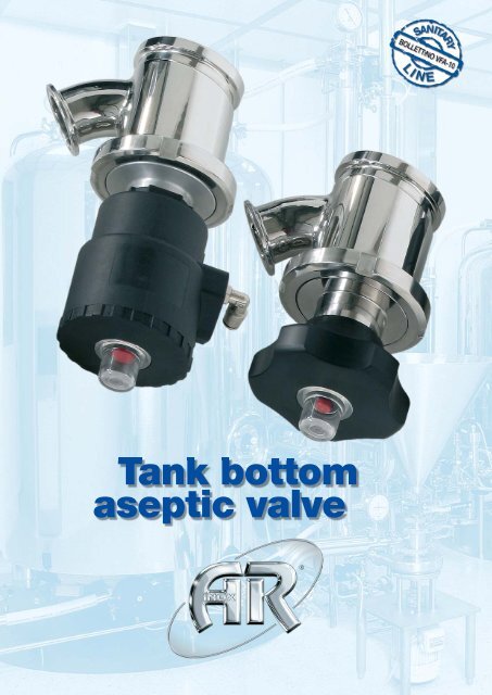
Tank bottom<br />
aseptic valve<br />
®
VFA10° TANK BOTTOM <strong>VA</strong>LVES<br />
RADIAL SEATED DIAPHRAGM<br />
Designed for pharmaceutical and biopharmaceutical applications, the radial seated diaphragm valves combines the best features of a piston<br />
valve with the inherent cleanability of a standard flat diaphragm valve.<br />
Aseptic design for pharmaceutical applications<br />
All materials of construction conform to FDA and cGMP requirements.<br />
The valve housing and the piping connections are self draining without dead-legs.<br />
All moving parts in the actuator are completely isolated from contact with the process.<br />
Available sizes 1”(25,4), 1”1/2 (38,1), 2” (50,8), 3” (76,2), 4” (101,6).<br />
Pressure directive The body are designed according to PED Directive 97/23/EC for Europe, ASME VIII Div.2 for US and F.E.M. (Finite<br />
Element Method) calculated, approved and certified by notified body. The valve body is machined from solid round bar in AISI 316L 1.4404 as<br />
standard, having other materials 1.4435 or hastelloy available upon request w/certs/heat #<br />
Extra equipment available on request<br />
Customized welding plate<br />
Proximity switch for indication of open/closed valve position<br />
Adjustable flow regulator<br />
CIP / SIP connection<br />
integrated SIP satellite valve<br />
Assembling tightening tool for locking ring<br />
The diaphragms are available in Silicone<br />
and TFM 1600 PTFE comply with<br />
FDA nd USP Class VI regulations<br />
The welding pad of the body is to be<br />
welded lush to the bottom vessel,<br />
result as an integral part of the tank<br />
surface for preventing stagnation of<br />
the media.<br />
The outlet connection is flush to the<br />
diaphragm to minimize hold-up volume,<br />
the standard outlet connection on<br />
the valve body is furnished on a 45°<br />
angle to the horizontal with an ASME-<br />
BPE ferrule, Other optional end connections<br />
upon request include ISO/<br />
DIN connections. 45° angle outlet facilitate<br />
the ease of fit-up and permit<br />
using standard tubing to connect<br />
upon request Steam and CIPports<br />
an be fabricated to the valve body<br />
providing access to the internal contact<br />
surfaces, of the valve as well as<br />
downstream piping<br />
The method of attachment for both<br />
the manual and automatic bonnet assemblies<br />
is trough the use of a bonnet<br />
adapter ring which is easily tightened<br />
or loosened utilizing standar spanner<br />
wrenches facilitating ease of maintenance.<br />
Available with manual thermoplastic<br />
handwheel ergonomically designed<br />
to provide ease of operation or the<br />
new thermoplastic pneumatic actuators<br />
NC spring return, as standard for<br />
general purpose use. Stainless steel<br />
hanwheel or pneumatic actuators, are<br />
available upon request.<br />
FOR HYDRO TEST….<br />
A blank cap will eventually be sold as<br />
an option to replace the topworks during<br />
hydro testing of the tank. This will<br />
protect the purity of the diaphragm for<br />
the system can be quite dirty during<br />
the tank hydro test.<br />
10°<br />
The 10° vertical offset enhances drainability while minimizing<br />
the internal sump within the vessel No problem<br />
associated with static material and cleaning or sterilizing<br />
The NAMUR connection for the control<br />
valve is provided as standard<br />
A bright red indicator provides positive<br />
indication of closed and open<br />
position, standard for all actuators.<br />
The pneumatic actuators come with<br />
a wide variety of accessories as mechanical<br />
or inductive control box and<br />
manually adjustable flow regulator, pilot<br />
valve…..
VFA10° - S/TC Flush Tank Bottom welded body<br />
Dimensions table<br />
CODE INCH DN ØTC ID A B C H W H1<br />
VFA10°-S/TC1” 1” 25 50,4 22,1 60 8 100 175 85 220<br />
VFA10°-S/TC1“1/2 1” ½ 40 50,4 34,8 75 8 100 185 116 270<br />
VFA10°-S/TC2“ 2” 50 64 47,5 115 10 100 200 140 330<br />
VFA10°-S/TC3“ 3” 80 90 72,9 125 12 100 260 140 350<br />
VFA10°-S/TC4” 4” 100 118,8 97,6 170 15 150 340 170 400<br />
VFA10° - TK/TC TK Connection removable body<br />
Dimensions table<br />
CODE ØTC ID TK ØTK H H1<br />
VFA10°-TK/TC1” 50,4 22,1 2” 100 190 240<br />
VFA10°-TK/TC1“1/2 50,4 34,8 2”1/2 112 200 280<br />
VFA10°-TK/TC2“ 64 47,5 4” 170 220 350<br />
VFA10°-TK/TC3“ 90 72,9 4” 170 270 380<br />
VFA10°-TK/TC4” 118,8 97,6 Not available for TK-Conn application<br />
Net volume of valve body cavity with PTFE diaphragm installed<br />
Tank bottom valve body available in the following type :<br />
VFA10°-S/TC VFA10°-TK/TC VFA- S/TC VFA- FL/TC<br />
10° Angled butt weld Angled TK removable body Flanged flush weld Flanged removable body<br />
Dimensions table<br />
Valve Code/Size INCH DN VFA10°-S/TC VFA10°-TK/TC VFA- S/TC VFA- FL/TC<br />
VFA10°-S/TC1” 1” 25 14 50 25 30<br />
VFA10°-S/TC1“1/2 1” ½ 40 27 72 75 105<br />
VFA10°-S/TC2“ 2” 50 92 235 85 150<br />
VFA10°-S/TC3“ 3” 80 170 310 320 Not available<br />
VFA10°-S/TC4” 4” 100 Not standard product, available on specific request only
VFA - S/TC Flush Tank Bottom welded body<br />
Dimensions table<br />
CODE ØTC ID A B C H W H1<br />
VFA-S/TC1” 50,4 22,1 100 15 100 165 85 230<br />
VFA-S/TC1“1/2 50,4 34,8 150 20 100 180 116 270<br />
VFA-S/TC2“ 64 47,5 180 20 100 200 140 330<br />
VFA-S/TC3“ 90 72,9 200 35 100 270 140 350<br />
VFA-S/TC4” 118,8 97,6 Available on request only<br />
VFA - FL/TC Flanged body removable<br />
Dimensions table<br />
CODE INCH DN ØTC ID A B H H1<br />
VFA-FL/TC1” 1” 25 50,4 22,1 100 15 175 240<br />
VFA-FL/TC1“1/2 1” ½ 40 50,4 34,8 150 20 190 285<br />
VFA-FL/TC2“ 2” 50 64 47,5 180 20 205 345<br />
VFA-FL/TC3“ 3” 80 90 72,9 200 35 275 370<br />
VFA-FL/TC4” 4” 100 118,8 97,6 Available on request only<br />
Special executions available on request:<br />
• welding plate with radius or bigger different<br />
thikness, special adaptors plate<br />
• 45°Outlet port butt weld<br />
• Stainless steel handle/pneumatic actuator<br />
• Adjustable flow regulator<br />
• Mechanical/inductive control box<br />
VFA - FL/O - Ring Flanged body removable<br />
Dimensions table<br />
CODE INCH DN ØTC P max A B H H1<br />
VFA-FL/TC1” 1” 25 50,4 7,5 bar 100 15 175 240<br />
VFA-FL/TC1“1/2 1” ½ 40 50,4 7,5 bar 150 20 190 285<br />
VFA-FL/TC2“ 2” 50 64 7,0 bar 180 20 205 345<br />
VFA-FL/TC3“ 3” 80 90 3,0 bar 200 35 275 370<br />
VFA-FL/TC4” 4” 100 118,8 97,6 Available on request only<br />
The new Tank Bottom valves “flush wall execution”<br />
with TFM 1600 PTFE bellow diaphragm for to solve<br />
all your problems with high viscosity products<br />
Radial seated diaphragm valve with unique<br />
O-Ring seal design minimizes bacteria traps
VFA10° <strong>VA</strong>LVE BODY Tank Bottom Valve - INFORMATION<br />
Design temperature, valve body:<br />
Design pressure, valve body:<br />
-80°C to 200°C (-112°F to 392°F)<br />
-1 bar to 10 bar (-14,5 psi to 101,5 psi)<br />
The valve body are designed according to PED Directive 97/23/EC for Europe, ASME VIII Div.2 for US<br />
and F.E.M. (Finite Element Method) calculated, approved and certified by notified body.<br />
Warning : The applied diaphragm and actuator may have a different design temperature and/or pressure.<br />
The weakest part in the assembled produc set the final, permitted design temperature and pressure limits.<br />
FLOW IN<br />
Flow rate<br />
In order to design valves for a process system correctly, the valve size is determined by the required flow rate.<br />
The Kv-value serves as a calculation basis for the different process conditions.<br />
This value is stated in the following table with regard to nominal diameter and standards.<br />
Kv-value (m3/h)<br />
The Kv-value is a parameter defining the flow rate of valves.<br />
It describes the amount of water from 5° to 25°C which<br />
flows through the valve at a pressure loss of 1 bar when<br />
the valve is 100% open<br />
Conversion<br />
For the correct Kv to Cv conversion calculation, use only<br />
the stated units formulas above.<br />
The Kv-value must be converted from (cubic meter/hour)<br />
by utilizing the following conversion factor.<br />
In the US the flow rate of water is measured with the<br />
Cv-value in US-gallons per minute (gpm) with a pressure<br />
drop of 1 PSI.<br />
conversion of Kv to Cv<br />
conversion of Cv to Kv<br />
Cv = 1,17 x Kv<br />
Kv = 0,86 x Cv<br />
OUT<br />
Flow characteristics with TFM 1600 PTFE diaphragm installed (Flow In to Out)<br />
Valve Code/Size INCH DN Kv-value (m3/h) Cv-value (gpm)<br />
VFA10°-S/TC1” 1” 25 10,5 12,2<br />
VFA10°-S/TC1” 1” ½ 40 15,0 17,5<br />
VFA10°-S/TC2“ 2” 50 32,0 37,4<br />
VFA10°-S/TC3“ 3” 80 78,0 91,2<br />
VFA10°-S/TC4” 4” 100 Not standard product, available on specific request only
VPA - VPAK<br />
ASEPTIC SAMPLING <strong>VA</strong>LVES<br />
RPS<br />
SANITARY SAMPLING <strong>VA</strong>LVES<br />
SSB<br />
SANITARY SAMPLING BOTTLE<br />
<strong>VA</strong> - VFA<br />
TANK BOTTOM <strong>VA</strong>LVES<br />
Realizzazione e Stampa - Crema (CR)<br />
VRN<br />
SPRING CHECK <strong>VA</strong>LVES<br />
VSS<br />
HIGH PURITY BALL <strong>VA</strong>LVES<br />
VF<br />
BUTTERFLY <strong>VA</strong>LVES<br />
HE<br />
DTS HEAT EXCHANGERS<br />
SP - SL<br />
SIGH GLASS-FLOW INDICATOR<br />
TC<br />
CLAMP FITTINGS<br />
TK - CONN<br />
TANK CONNECTIONS<br />
RE - FLEX<br />
SILICONE HOSE & FITTINGS<br />
MM<br />
MAGNETIC MIXER<br />
DD<br />
REPLACEMENT DIAPHRAGMS<br />
RSH<br />
ROTATIVE SPRAY HEAD<br />
®<br />
<strong>AERRE</strong> INOX s.r.l.<br />
Lottizzazione Gerola<br />
I-26010 Fiesco (Cremona)<br />
Tel. +39 0374 370 828 - Fax +39 0374 370 833<br />
www.aerreinox.it<br />
Get the information you need and more at info.aerreinox.it