Model No.: CENTRIFUGAL PUMPS FPE/FP…V Series
Model No.: CENTRIFUGAL PUMPS FPE/FP…V Series
Model No.: CENTRIFUGAL PUMPS FPE/FP…V Series

Create successful ePaper yourself
Turn your PDF publications into a flip-book with our unique Google optimized e-Paper software.
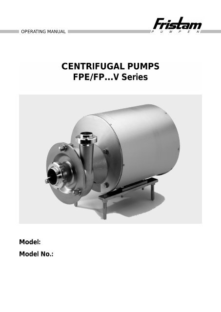
OPERATING MANUAL<br />
<strong>Model</strong>:<br />
<strong>Model</strong> <strong>No</strong>.:<br />
<strong>CENTRIFUGAL</strong> <strong>PUMPS</strong><br />
<strong>FPE</strong>/<strong>FP…V</strong> <strong>Series</strong><br />
P U M P E N
OPERATING MANUAL <strong>FPE</strong><br />
P U M P E N<br />
1. Disassembly 2<br />
1.1 General 2<br />
1.2 Impeller 2<br />
1.3 Complete disassembly 2<br />
2. Assembly 2<br />
2.1 General 2<br />
2.1.1 Setting the gap 2<br />
2.1.2 Screw tightening torque 3<br />
2.2 <strong>FPE</strong> assembly 3<br />
2.3 <strong>FPE</strong> with double shaft seal 3
1. Disassembly<br />
1.1 General<br />
• Disconnect the pump from<br />
the power supply so that it is deenergised.<br />
• If fitted, close the shut-off valve<br />
in the suction pipe and discharge<br />
pipe.<br />
• Undo the suction/discharge<br />
connections and remove the<br />
pump from the system.<br />
• In the case of dangerous pumping<br />
media, legal and works<br />
safety directions must be observed.<br />
For highly polished surfaces:<br />
When tightening or untightening the<br />
impeller nut please use softer<br />
material tool inlets (copper sheet)<br />
in order to prevent surface damage.<br />
1.2 Impeller and shaft seal<br />
• Unscrew the cover and drain the<br />
pump, clean it, if necessary.<br />
• Undo the impeller nut.<br />
• Pull off the impeller from the shaft<br />
and remove the feather key.<br />
• Carefully dismantle the shaft<br />
seal parts in accordance with the<br />
order-related documentation.<br />
2<br />
OPERATING MANUAL <strong>FPE</strong><br />
1.3 Complete disassembly<br />
• Undo the clamping screw resp.<br />
hex-screws between casing and<br />
lantern (only for 1051/2, 1151/2,<br />
1231/2, 1251/2, 101/102–200,<br />
101/102–250).<br />
• Pull off the casing.<br />
• Undo the screws between the<br />
motor flange and clamping disc/<br />
lantern.<br />
• Pull off the clamping disc/lantern.<br />
• Undo the screws of the shrink-fit<br />
ring.<br />
• Release the tensioning rings from<br />
the clamping ring.<br />
• Pull off the pump’s hollow shaft<br />
from the motor shaft.<br />
• Pull off the shrink-fit ring from the<br />
pump’s hollow shaft.<br />
2. Assembly<br />
2.1 General<br />
Before assembling the pump, the<br />
following has to be done:<br />
• The parts have to be cleaned.<br />
• The sealing area has to be<br />
cleaned.<br />
• All parts have to be checked for<br />
precision fit and, if necessary,<br />
reworked, with the exception of<br />
the sliding surfaces of the shaft<br />
seal.<br />
• Worn parts have to be replaced.<br />
• O-rings and gaskets always have<br />
to be replaced before assembly.<br />
2.1.1 Setting the gap<br />
The gap size of the pump must be<br />
reset in accordance with Tab 1.<br />
Tab. 1: Gap sizes<br />
gap<br />
impeller cover<br />
cover height<br />
Pump Type Axial gap<br />
711/712<br />
721/722<br />
741/742<br />
3401/3402<br />
3521/3522<br />
3531/3532<br />
3541/3542<br />
3451/3552<br />
3551/3552<br />
751/752<br />
1051/1052<br />
1151/1152<br />
1231/1232<br />
1251/1252<br />
101/102-200<br />
101/102-250<br />
Impeller/<br />
cover<br />
0.5 mm<br />
0.5 mm 1.0 mm<br />
1.0 mm<br />
0.7 mm 0.6 mm<br />
2.0 mm<br />
Impeller/<br />
casing<br />
1.0 mm 1.5 mm<br />
0.5 mm 1.2 mm
2.1.2 Screw tightening torque<br />
The screw tightening torque in<br />
the tables below must be complied<br />
with.<br />
M6 M8 M10 M12 M16 M20<br />
Nm 10 25 49 85 210 420<br />
Tab. 2: Class 8.8 steel screws<br />
M6 M8 M10 M12 M16 M20<br />
Nm 7,3 17,5 35 60 144 281<br />
Tab. 3: Stainless steel screws<br />
A2-70 and A4-70<br />
2.2 Pump assembly<br />
1. Remove the feather key from<br />
the motor shaft.<br />
2. Degrease the motor shaft and<br />
bore of the hollow shaft.<br />
3. Insert half feather key into<br />
the motor shaft (only for bigger<br />
motors above >30 kW).<br />
4. Seal the motor shaft around<br />
the shaft shoulder with a sealing<br />
gel (e.g. Stucarit sealing gel<br />
309).<br />
5. Push the hollow shaft with<br />
shrink-fit ring onto the motor<br />
shaft up to the shaft shoulder.<br />
6. Tighten the hexagon socket<br />
screws of the shrink-fit ring<br />
in diagonally opposite sequence<br />
(see Tab. 4).<br />
Hexagon<br />
socket screw<br />
M5<br />
Tightening<br />
torque<br />
6Nm<br />
M6 12 Nm<br />
Tab. 4: Tightening torque for the<br />
fastening screws of the shrinkfit<br />
ring<br />
7. Check the hollow shaft for concentricity<br />
and align.<br />
Concentricity tolerance:<br />
max. 0,06 mm for motors<br />
below 30 kW<br />
max. 0,08 mm for motors<br />
above 30 kW<br />
8. Screw the clamping disc/lantern<br />
to the motor flange.<br />
9. Insert the shaft seal housing<br />
or stationary ring with O-ring into<br />
the pump casing and secure<br />
(in accordance with the orderrelated<br />
documentation).<br />
10. Screw pump casing and clamping<br />
disc/lantern together so as<br />
to be fingertight.<br />
11. Fit the front seal set of the<br />
shaft seal. Cut the Nylon lock<br />
ring and put it into the prepared<br />
groove behind the thread<br />
of the shaft.<br />
12. Insert the O-ring into the impeller<br />
nut. Push the impeller on<br />
to the pump shaft. Secure<br />
the impeller against twisting<br />
and tighten the impeller nut<br />
with 100 Nm.<br />
13. Set the gap size of the cover,<br />
impeller and casing by shifting<br />
the pump casing within the<br />
clamped joint, resp. measure<br />
the gap size and adjust by fitting<br />
shims between casing and<br />
lantern (only for 1051/2, 1151/2,<br />
1231/2, 1251/2, 101/102–200,<br />
101/102–250) (see Tab. 1: Gap<br />
sizes).<br />
14. Tighten the clamping screw<br />
with the following torque:<br />
– M 10 with 45 Nm<br />
– M 12 with 75 Nm<br />
or hex-screws with torque specified.<br />
15. Place the cover with O-ring<br />
onto the casing and tighten.<br />
P U M P E N<br />
2.3 Pumps with double shaft seal<br />
1. Remove the feather key from<br />
the motor shaft.<br />
2. Degrease the motor shaft and<br />
bore of the hollow shaft.<br />
For pumps in <strong>FPE</strong> execution<br />
radial gasket needs to be fitted<br />
onto a speedy – sleeve.<br />
3. Use a piece of pipe (length between<br />
120 to 150 mm) to push<br />
the sleeve onto the shaft. Inner<br />
diameter of pipe 23 mm (for<br />
22 mm shaft), 36 mm (for 35 mm<br />
shaft).<br />
For pumps in <strong>FPE</strong> execution<br />
with 22 mm shaft only: Sealing<br />
cover with radial gasket to be<br />
fitted to pump housing. Flushing<br />
pipes in vertical direction,<br />
then threaded pins to be fixed<br />
manually.<br />
4. Insert half feather key into the<br />
motor shaft (only for bigger motors<br />
above 30 kW).<br />
5. Seal the motor shaft around the<br />
shaft shoulder with sealing gel<br />
(e.g. Stucarit sealing gel 309).<br />
6. Push the hollow shaft with<br />
shrink-fit ring onto the motor<br />
shaft up the shaft shoulder.<br />
7. Tighten the hexagon socket<br />
screws of the shrink-fit ring<br />
in diagonally opposite sequence<br />
(see Tab. 4).<br />
8. Check the hollow shaft for concentricity<br />
and align.<br />
Concentricity tolerance:<br />
max. 0,06 mm for motors<br />
below 30 kW<br />
max. 0,08 mm for motors<br />
above 30 kW<br />
3
4<br />
OPERATING MANUAL <strong>FPE</strong> P U M P E N<br />
9. Screw the clamping disc/<br />
lantern to the motor flange.<br />
For pumps in <strong>FP…V</strong> execution<br />
only: Push rear mechanical seal<br />
unit onto the shaft (according<br />
to the order-related documentation).<br />
10. Insert the shaft seal housing or<br />
stationary ring with O-ring into<br />
the pump casing and secure (in<br />
accordance with the order-related<br />
documentation).<br />
11. Screw pump casing and clamping<br />
disc/lantern together so as<br />
to be fingertight.<br />
12. Flushing pipes to screw into<br />
the sealing cover to be sealed<br />
with sealing paste.<br />
13. Fit the front seal set of the<br />
shaft seal. Cut the Nylon lock<br />
ring and put it into the prepared<br />
groove behind the thread<br />
of the shaft.<br />
14. Insert the O-ring into the impeller<br />
nut. Push the impeller on<br />
to the pump shaft. Secure<br />
the impeller against twisting and<br />
tighten the impeller nut with<br />
100 Nm.<br />
15. Set the gap size of the cover,<br />
impeller and casing by shifting<br />
the pump casing within the<br />
clamped joint, resp. measure<br />
the gap size and adjust by fitting<br />
shims between casing and<br />
lantern (only for 1051/2, 1151/2,<br />
1231/2, 1251/2, 101/102–200,<br />
101/102–250) (see Tab. 1: Gap<br />
sizes).<br />
16. Tighten the clamping screw<br />
with the following tightening<br />
torque:<br />
– M 10 with 45 Nm<br />
– M 12 with 75 Nm<br />
or hex-screws with torque<br />
specified.<br />
17. Place the cover with O-ring onto<br />
the casing and tighten.<br />
Each time the impeller is assembled,<br />
a check must be<br />
made to ensure that it does not<br />
chafe at any point, and the<br />
Nylon lock ring has to be replaced.
Germany<br />
Australia<br />
Fristam Australia Pty. Ltd.<br />
Bayswater, VIC<br />
Austria<br />
Fristam Pumpen GmbH<br />
Vienna<br />
Belgium<br />
Luxembourg<br />
Fristam N.V.<br />
Aartselaar<br />
France<br />
Pompes Fristam S.A.<br />
<strong>No</strong>isy-le-Sec<br />
FRISTAM Pumpen<br />
F. Stamp KG (GmbH & Co.)<br />
P.O. Box 80 08 80<br />
21008 Hamburg (Germany)<br />
Please see www.fristam.de for addresses and further information.<br />
Great Britain<br />
Fristam Pumps (UK) Ltd.<br />
Hailsham<br />
India<br />
Fristam Pumps (I) Pvt. Ltd.<br />
Pune<br />
Italy<br />
Fristam Italia S.r.l.<br />
Borgo Ticino (NO)<br />
Japan<br />
Stamp Pumps of Japan<br />
Ltd.<br />
Tokio<br />
Netherlands<br />
Fristam B.V.<br />
De Meern<br />
New Zealand<br />
Fristam Pumps Ltd.<br />
Cambridge<br />
Poland<br />
Fristam Polska Sp.z.o.o.<br />
Warsaw<br />
Russian Federation<br />
Fristam Pumpen R.A.<br />
Moskow<br />
Scandinavia<br />
Fristam Pumper A/S<br />
Saeby<br />
South/East Asia<br />
Fristam Pumpen (S.E.A.)<br />
Pte.Ltd.<br />
Singapore<br />
P U M P E N<br />
Phone +49 (0) 40 / 7 25 56-0<br />
Fax +49 (0) 40 / 7 25 56-166<br />
E-Mail info@fristam.de<br />
Ukraine<br />
Fristam Kiev Ltd.<br />
Kiev<br />
USA/Canada<br />
Mexico<br />
South America<br />
Fristam Pumps, Inc.<br />
Middleton, WI