Model No.: CENTRIFUGAL PUMPS FPE/FP…V Series
Model No.: CENTRIFUGAL PUMPS FPE/FP…V Series
Model No.: CENTRIFUGAL PUMPS FPE/FP…V Series

You also want an ePaper? Increase the reach of your titles
YUMPU automatically turns print PDFs into web optimized ePapers that Google loves.
2.1.2 Screw tightening torque<br />
The screw tightening torque in<br />
the tables below must be complied<br />
with.<br />
M6 M8 M10 M12 M16 M20<br />
Nm 10 25 49 85 210 420<br />
Tab. 2: Class 8.8 steel screws<br />
M6 M8 M10 M12 M16 M20<br />
Nm 7,3 17,5 35 60 144 281<br />
Tab. 3: Stainless steel screws<br />
A2-70 and A4-70<br />
2.2 Pump assembly<br />
1. Remove the feather key from<br />
the motor shaft.<br />
2. Degrease the motor shaft and<br />
bore of the hollow shaft.<br />
3. Insert half feather key into<br />
the motor shaft (only for bigger<br />
motors above >30 kW).<br />
4. Seal the motor shaft around<br />
the shaft shoulder with a sealing<br />
gel (e.g. Stucarit sealing gel<br />
309).<br />
5. Push the hollow shaft with<br />
shrink-fit ring onto the motor<br />
shaft up to the shaft shoulder.<br />
6. Tighten the hexagon socket<br />
screws of the shrink-fit ring<br />
in diagonally opposite sequence<br />
(see Tab. 4).<br />
Hexagon<br />
socket screw<br />
M5<br />
Tightening<br />
torque<br />
6Nm<br />
M6 12 Nm<br />
Tab. 4: Tightening torque for the<br />
fastening screws of the shrinkfit<br />
ring<br />
7. Check the hollow shaft for concentricity<br />
and align.<br />
Concentricity tolerance:<br />
max. 0,06 mm for motors<br />
below 30 kW<br />
max. 0,08 mm for motors<br />
above 30 kW<br />
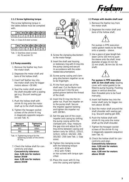
8. Screw the clamping disc/lantern<br />
to the motor flange.<br />
9. Insert the shaft seal housing<br />
or stationary ring with O-ring into<br />
the pump casing and secure<br />
(in accordance with the orderrelated<br />
documentation).<br />
10. Screw pump casing and clamping<br />
disc/lantern together so as<br />
to be fingertight.<br />
11. Fit the front seal set of the<br />
shaft seal. Cut the Nylon lock<br />
ring and put it into the prepared<br />
groove behind the thread<br />
of the shaft.<br />
12. Insert the O-ring into the impeller<br />
nut. Push the impeller on<br />
to the pump shaft. Secure<br />
the impeller against twisting<br />
and tighten the impeller nut<br />
with 100 Nm.<br />
13. Set the gap size of the cover,<br />
impeller and casing by shifting<br />
the pump casing within the<br />
clamped joint, resp. measure<br />
the gap size and adjust by fitting<br />
shims between casing and<br />
lantern (only for 1051/2, 1151/2,<br />
1231/2, 1251/2, 101/102–200,<br />
101/102–250) (see Tab. 1: Gap<br />
sizes).<br />
14. Tighten the clamping screw<br />
with the following torque:<br />
– M 10 with 45 Nm<br />
– M 12 with 75 Nm<br />
or hex-screws with torque specified.<br />
15. Place the cover with O-ring<br />
onto the casing and tighten.<br />
P U M P E N<br />
2.3 Pumps with double shaft seal<br />
1. Remove the feather key from<br />
the motor shaft.<br />
2. Degrease the motor shaft and<br />
bore of the hollow shaft.<br />
For pumps in <strong>FPE</strong> execution<br />
radial gasket needs to be fitted<br />
onto a speedy – sleeve.<br />
3. Use a piece of pipe (length between<br />
120 to 150 mm) to push<br />
the sleeve onto the shaft. Inner<br />
diameter of pipe 23 mm (for<br />
22 mm shaft), 36 mm (for 35 mm<br />
shaft).<br />
For pumps in <strong>FPE</strong> execution<br />
with 22 mm shaft only: Sealing<br />
cover with radial gasket to be<br />
fitted to pump housing. Flushing<br />
pipes in vertical direction,<br />
then threaded pins to be fixed<br />
manually.<br />
4. Insert half feather key into the<br />
motor shaft (only for bigger motors<br />
above 30 kW).<br />
5. Seal the motor shaft around the<br />
shaft shoulder with sealing gel<br />
(e.g. Stucarit sealing gel 309).<br />
6. Push the hollow shaft with<br />
shrink-fit ring onto the motor<br />
shaft up the shaft shoulder.<br />
7. Tighten the hexagon socket<br />
screws of the shrink-fit ring<br />
in diagonally opposite sequence<br />
(see Tab. 4).<br />
8. Check the hollow shaft for concentricity<br />
and align.<br />
Concentricity tolerance:<br />
max. 0,06 mm for motors<br />
below 30 kW<br />
max. 0,08 mm for motors<br />
above 30 kW<br />
3