

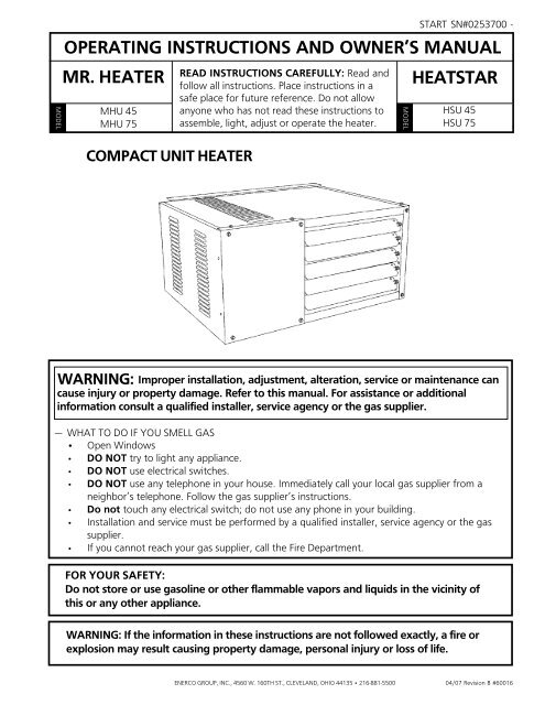
operating instructions and owner's manual mr. heater - HeatStar by ...
operating instructions and owner's manual mr. heater - HeatStar by ...
operating instructions and owner's manual mr. heater - HeatStar by ...

You also want an ePaper? Increase the reach of your titles
YUMPU automatically turns print PDFs into web optimized ePapers that Google loves.
MODEL<br />
OPERATING INSTRUCTIONS AND OWNER’S MANUAL<br />
MR. HEATER<br />
MHU 45<br />
MHU 75<br />
COMPACT UNIT HEATER<br />
READ INSTRUCTIONS CAREFULLY: Read <strong>and</strong><br />
follow all <strong>instructions</strong>. Place <strong>instructions</strong> in a<br />
safe place for future reference. Do not allow<br />
anyone who has not read these <strong>instructions</strong> to<br />
assemble, light, adjust or operate the <strong>heater</strong>.<br />
MODEL<br />
START SN#0253700 -<br />
HEATSTAR<br />
HSU 45<br />
HSU 75<br />
WARNING:<br />
Improper installation, adjustment, alteration, service or maintenance can<br />
cause injury or property damage. Refer to this <strong>manual</strong>. For assistance or additional<br />
information consult a qualified installer, service agency or the gas supplier.<br />
— WHAT TO DO IF YOU SMELL GAS<br />
• Open Windows<br />
• DO NOT try to light any appliance.<br />
• DO NOT use electrical switches.<br />
• DO NOT use any telephone in your house. Immediately call your local gas supplier from a<br />
neighbor’s telephone. Follow the gas supplier’s <strong>instructions</strong>.<br />
• Do not touch any electrical switch; do not use any phone in your building.<br />
• Installation <strong>and</strong> service must be performed <strong>by</strong> a qualified installer, service agency or the gas<br />
supplier.<br />
• If you cannot reach your gas supplier, call the Fire Department.<br />
FOR YOUR SAFETY:<br />
Do not store or use gasoline or other flammable vapors <strong>and</strong> liquids in the vicinity of<br />
this or any other appliance.<br />
WARNING: If the information in these <strong>instructions</strong> are not followed exactly, a fire or<br />
explosion may result causing property damage, personal injury or loss of life.<br />
ENERCO GROUP, INC., 4560 W. 160TH ST., CLEVELAND, OHIO 44135 • 216-881-5500<br />
04/07 Revision B #60016
04/07 Revision B #60016<br />
Enerco | Compact Unit Heater<br />
2<br />
Operating Instructions <strong>and</strong> Owner’s Manual
WARNING:<br />
YOUR SAFETY IS IMPORTANT TO YOU AND TO OTHERS,<br />
SO PLEASE READ THESE INSTRUCTIONS BEFORE YOU<br />
OPERATE THIS HEATER.<br />
GENERAL HAZARD WARNING:<br />
FAILURE TO COMPLY WITH THE PRECAUTIONS AND<br />
INSTRUCTIONS PROVIDED WITH THIS HEATER, CAN<br />
RESULT IN DEATH, SERIOUS BODILY INJURY AND<br />
PROPERTY LOSS OR DAMAGE FROM HAZARDS OF FIRE,<br />
EXPLOSION, BURN, ASPHYXIATION, CARBON MONOX-<br />
IDE POISONING, AND/OR ELECTRICAL SHOCK.<br />
ONLY PERSONS WHO CAN UNDERSTAND AND FOLLOW<br />
THE INSTRUCTIONS SHOULD USE OR SERVICE THIS<br />
HEATER.<br />
IF YOU NEED ASSISTANCE OR HEATER INFORMATION<br />
SUCH AS AN INSTRUCTIONS MANUAL, LABELS, ETC.<br />
CONTACT THE MANUFACTURER.<br />
WARNING:<br />
FIRE, BURN, INHALATION, AND EXPLOSION HAZARD.<br />
KEEP SOLID COMBUSTIBLES, SUCH AS BUILDING<br />
MATERIALS, PAPER OR CARDBOARD, A SAFE DIS-<br />
TANCE AWAY FROM THE HEATER AS RECOMMENDED<br />
BY THE INSTRUCTIONS NEVER USE THE HEATER IN<br />
SPACES WHICH DO OR MAY CONTAIN VOLATILE OR<br />
AIRBORNE COMBUSTIBLES, OR PRODUCTS SUCH AS<br />
GASOLINE, SOLVENTS, PAINT THINNER, DUST PAR-<br />
TICLES OR UNKNOWN CHEMICALS.<br />
WARNING:<br />
The State of California requires the following warning:<br />
COMBUSTION BY-PRODUCTS PRODUCED WHEN<br />
USING THIS PRODUCT CONTAIN CARBON MONOXIDE,<br />
A CHEMICAL KNOWN TO THE STATE OF CALIFORNIA<br />
TO CAUSE CANCER AND BIRTH DEFECTS (OR OTHER<br />
REPRODUCTIVE HARM).<br />
CONTENTS<br />
UNIT DIMENSIONS .................................................................. 4<br />
SHIPPING ................................................................................. 5<br />
REQUIREMENTS ....................................................................... 5<br />
UNIT HEATER INSTALLATION .................................................. 6<br />
COMBUSTION & VENTILATION AIR ......................................... 6<br />
VENTING .......................................................................... 6 - 10<br />
ELECTRICAL CONNECTIONS ................................................... 10<br />
GAS CONNECTION ................................................................ 11<br />
LEAK CHECK .......................................................................... 11<br />
START-UP OPERATION ........................................................... 11<br />
HEATING SEQUENCE OF OPERATION .................................... 12<br />
IGNITION CONTROL LED ........................................................ 12<br />
ADJUSTMENTS ...................................................................... 12<br />
SERVICE ................................................................................. 13<br />
WIRING DIAGRAM ................................................................. 14<br />
PARTS LIST............................................................................. 16<br />
WARRANTY ........................................................................... 18<br />
Enerco | Compact Unit Heater 3 Operating Instructions <strong>and</strong> Owner’s Manual<br />
04/07 Revision B #60016
MHU45/MHU75 AND HSU45/HSU75 UNIT DIMENSIONS<br />
(N-NATURAL GAS, P-PROPANE)<br />
HANGING<br />
BRACKETS<br />
MOUNTING SLOTS (Typical)<br />
5/16 x 3 Inches (8 x 76 mm)<br />
AIR<br />
FLOW<br />
HEAT EXCHANGER<br />
(ALUMINIZED STEEL)<br />
DIMENSION 45 75<br />
A 12 (305) 17 (432)<br />
B 5-1/2 (140) 6-1/2 (165)<br />
C 4-1/4 (108) 6-3/4 (171)<br />
TOP VIEW<br />
ELECTRICAL<br />
INLETS<br />
HANGING<br />
BRACKETS (2)<br />
DIRECT<br />
DRIVE FAN<br />
FLUE<br />
OUTLET<br />
GAS<br />
INLET<br />
SERVICE<br />
ACCESS PANEL<br />
ADJUSTABLE<br />
LOUVERS<br />
SIDE VIEW<br />
START–UP AND PERFORMANCE CHECK LIST<br />
Job Name: _________________________________________<br />
Job Location: _______________________________________<br />
Installer: __________________________________________<br />
Unit Model No.: ____________________________________<br />
Job No.: ______________________________________<br />
City: _________________________________________<br />
City: _________________________________________<br />
Serial No.: ____________________________________<br />
Date: ______________________________________<br />
State/Province: ______________________________<br />
State/Province: ______________________________<br />
Service Technician: ___________________________<br />
Electrical Connections Tight? ______________________________________________<br />
Supply Voltage __________________________________________________________<br />
Gas Piping Connections Tight & Leak-Tested? _________________________________<br />
Motor Amps ____________________________________________________________<br />
Furnace Btu Input ________________________________________________________<br />
Line Pressure ____________________________________________________________<br />
Flue Connections Tight? _________________________________________________<br />
Fan Timer Operation Checked? ____________________________________________<br />
THERMOSTAT<br />
Calibrated? ____________________________________________________________<br />
Heat Anticipator Properly Set?<br />
Level? _________________________________________________________________<br />
Manifold Pressure w.c. ____________________________________________________<br />
04/07 Revision B #60016<br />
Enerco | Compact Unit Heater<br />
4<br />
Operating Instructions <strong>and</strong> Owner’s Manual
SHIPPING<br />
The <strong>heater</strong> is completely assembled. Installation <strong>instructions</strong>, two<br />
mounting brackets (shipped loose), <strong>and</strong> a flue transition are<br />
included. Check the unit for shipping damage. The receiving<br />
party should contact the last carrier immediately if any shipping<br />
damage is found.<br />
REQUIREMENTS – CSA IN THE USA<br />
Installation of gas unit <strong>heater</strong>s must conform with local building<br />
codes or, in the absence of local codes, with the current National<br />
Fuel Gas Code ANSI Z223.1.<br />
Installation in aircraft hangers must be in accordance with the<br />
current St<strong>and</strong>ard for Aircraft Hangers ANSI/NFPA No. 409.<br />
Installation in parking structures must be in accordance with the<br />
current St<strong>and</strong>ard for Parking Structures ANSI/NFPA No. 88A.<br />
Installation in repair garages must be in accordance with the<br />
current St<strong>and</strong>ard for Repair Garages ANSI/NFPA No. 88B.<br />
These units are approved for residential applications. For<br />
installation in a residential garage these units must be installed<br />
so that burners <strong>and</strong> ignition source are located no less than 18"<br />
(457mm) above floor. Heater must be located or protected to<br />
avoid physical damage <strong>by</strong> vehicles. Refer to the National Fuel Gas<br />
Code, ANSI Z223.1, current edition.<br />
Authorities having jurisdiction should be consulted before NFPA<br />
installation. Air for combustion <strong>and</strong> ventilation must conform to<br />
the methods outlined in ANSI Z223.1, section 5.3, Air for<br />
Combustion <strong>and</strong> Ventilation, or applicable provisions of local<br />
building codes. The National Fuel Gas Code is available from:<br />
American National St<strong>and</strong>ard Institute Inc.<br />
11 West 42nd Street<br />
New York, NY 10036<br />
These units are CSA International design certified. These unit<br />
<strong>heater</strong>s are certified for installation to combustible material as<br />
listed in table 1 <strong>and</strong> on unit rating plate. Accessibility <strong>and</strong> service<br />
clearances must be observed in addition to fire protection<br />
clearances.<br />
All electrical wiring <strong>and</strong> ground for unit must be in accordance<br />
with the regulations of the current National Electric Code ANSI/<br />
No. 70.<br />
The National Electric Code is available from:<br />
National Fire Protection Association<br />
1 Batterymarch Park<br />
PO Box 9101<br />
Quincy, MA 02269-9101<br />
REQUIREMENTS – CSA IN CANADA<br />
The <strong>instructions</strong> are intended only as a general guide <strong>and</strong> do not<br />
supersede local codes in any way. Authorities having jurisdiction<br />
should be consulted before installation. The installation must<br />
conform with local building codes or in the absence of local<br />
codes, with the current CSA B149.1, Natural Gas <strong>and</strong> Propane<br />
Installation Code. All electrical wiring <strong>and</strong> grounding for the unit<br />
must also comply with the Canadian Electrical Code CSA C22.1,<br />
current edition.<br />
These unit <strong>heater</strong>s are CSA International. certified for the<br />
clearances to combustible material listed on the rating plate <strong>and</strong><br />
table 1. Adequate clearance around air openings into the<br />
combustion chamber, clearances from combustible material, <strong>and</strong><br />
provisions for accessibility <strong>and</strong> for combustion <strong>and</strong> ventilation air<br />
supply. Provision shall be made for service accessibility to the<br />
<strong>heater</strong>. Note that fire protection clearances may be exceeded to<br />
provide additional space for service <strong>and</strong> accessibility.<br />
GARAGE INSTALLATIONS:<br />
Installation in parking structures must be in accordance with the<br />
current St<strong>and</strong>ard for Parking Structures ANSI/NFPA No. 88A.<br />
Installation in repair garages must be in accordance with the<br />
current St<strong>and</strong>ard for Repair Garages ANSI/NFPA No. 88B.<br />
1. In a storage area, clearance from <strong>heater</strong>s to combustible<br />
materials must be such that the material shall not attain a<br />
temperature above 160°F <strong>by</strong> continuous operation of the<br />
unit.<br />
2. Eight foot minimum clearance from the floor to the bottom<br />
of the <strong>heater</strong> must be maintained. Refer to the CSA B149.1,<br />
Natural Gas <strong>and</strong> Propane Installation Code<br />
AIRCRAFT HANGER:<br />
TABLE 1<br />
UNIT CLEARANCES<br />
Top Sides Access Panel<br />
in mm in mm in mm<br />
1 25 1 25 18 457<br />
Bottom Rear Single Wall Vent*<br />
in mm in mm in mm<br />
0 0 18 456 6 152<br />
*Except for listed clearance thimbles.<br />
Installation of gas unit <strong>heater</strong>s must conform with local building<br />
codes or, in the absence of local codes, with the current National<br />
Fuel Gas Code ANSI Z223.1.<br />
1. In an area where aircraft are housed or serviced, 10'<br />
minimum clearance from highest surface of aircraft to<br />
bottom of the <strong>heater</strong> must be maintained.<br />
2. In other areas, 8' minimum clearance from the floor to<br />
bottom of <strong>heater</strong> must be maintained.<br />
3. Heaters should be located so as to be protected from<br />
damage from aircraft or other appliances needed for<br />
servicing of aircraft. Refer to requirements of the enforcing<br />
authorities.<br />
Enerco | Compact Unit Heater 5 Operating Instructions <strong>and</strong> Owner’s Manual<br />
04/07 Revision B #60016
These units are approved for residential applications. For<br />
installation in a residential garage, these units must be installed so<br />
that burners <strong>and</strong> ignition source are located no less than 18”<br />
(457mm) above floor. Heater must be located or protected to<br />
avoid physical damage <strong>by</strong> vehicles. Refer to CSA B149.1, Natural<br />
Gas <strong>and</strong> Propane Installation Code current edition.<br />
In a confined area, the <strong>heater</strong> must be installed in accordance with<br />
the CSA B149.1, Natural Gas <strong>and</strong> Propane Installation Code. Be<br />
sure to check with local codes <strong>and</strong> ordinances for additional<br />
requirements.<br />
UNIT HEATER INSTALLATION<br />
Unit is shipped ready for installation. Unit may be installed as<br />
shown in figure 1 or inverted 180 o depending on desired location<br />
as governed <strong>by</strong> clearances, vent connection, air direction, gas<br />
supply, electrical supply <strong>and</strong> service accessibility.<br />
1. If installing unit in an inverted position: Remove <strong>and</strong> retain<br />
screws securing door <strong>and</strong> rotate door 180 o . Secure with<br />
retained screws. Rotate louvers directing airflow as desired.<br />
2. Choose location for mounting brackets.<br />
3. Remove <strong>and</strong> retain three screws along top edge<br />
(bottomedge when inverted) of front of unit.<br />
4. Align screw holes on mounting bracket with holes along top<br />
edge (either upright or inverted) of unit. Secure one<br />
mounting bracket to front of unit with retained<br />
screws.Secure other mounting bracket to back of unit with<br />
screws provided in bag assembly containing flue transition.<br />
5. To support unit, secure mounting bracket to ceiling joist or<br />
truss. Unit may also hang on rods as shown in figure 1.<br />
MOUNTING<br />
BRACKETS (2)<br />
INSTALL UNIT HEATER<br />
SUPPORT<br />
RODS<br />
Code, ANSI Z223.1, in the U.S.A., CSA B149.1 Natural Gas <strong>and</strong><br />
Propane Installation Code, or applicable provisions of local building<br />
codes.<br />
All gas fired appliances require air to be used for the combustion<br />
process. In many buildings today, there is a negative indoor air<br />
pressure caused <strong>by</strong> exhaust fans, etc. If sufficient quantities of<br />
combustion air are not available, the <strong>heater</strong> or another or another<br />
appliance will operate in an inefficient manner, resulting in<br />
incomplete combustion which can result in the production of<br />
excessive carbon monoxide.<br />
CAUTION Insufficient combustion air can cause headaches,<br />
nausea, dizziness, asphyxiation or death.<br />
If indoor air is to be used for combustion, it must be free of the<br />
following substances or the life of the heat exchanger will be<br />
adversely affected: chlorine, carbon tetrachloride, cleaning solvent,<br />
halogen refrigerants, acids, cements <strong>and</strong> glues, printing inks,<br />
fluorides, paint removers, varnishes, or any other corrosives.<br />
VENTING<br />
A – GENERAL RECOMMENDATIONS AND<br />
REQUIREMENTS<br />
NOTE: The vent is a passageway, vertical or nearly so, used to<br />
convey flue gases from an appliance, or its vent connector, to the<br />
outside atmosphere. The vent connector is the pipe or duct that<br />
connects a fuel-gas burning appliance to a vent or chimney.<br />
Unit <strong>heater</strong>s must be vented in compliance with all local codes or<br />
requirements of the local utility, the current st<strong>and</strong>ards of the<br />
(American) National Fuel Gas Code, ANSI Z223.1 or (Canada) CSA<br />
B149.1 Natural Gas <strong>and</strong> Propane Installation Code, <strong>and</strong> the<br />
following <strong>instructions</strong>.<br />
A metal stamped/extruded transition is supplied with this certified<br />
unit. It must not be modified or altered <strong>and</strong> must be installed on<br />
the outlet of the induced draft blower assembly prior to the<br />
installation of the vent or vent connector. Failure to comply with<br />
this requirement will void the certification of the unit <strong>by</strong> the<br />
approval agencies. All joints shall be secured with at least two<br />
corrosion resistant screws. All joints must be checked for gas<br />
tightness after installation.<br />
TABLE 2<br />
MAXIMUM VENT LENGTHS<br />
HORIZONTAL VENTS<br />
FIGURE 1<br />
COMBUSTION AND VENTILATION AIR<br />
Adequate facilities for supplying air for combustion <strong>and</strong> ventilation<br />
must be provided in accordance with the latest edition of section<br />
5.3, Air for Combustion <strong>and</strong> Ventilation, of the National Fuel Gas<br />
No. of ft m<br />
Elbows<br />
1 25 7.6<br />
2 20 6.1<br />
3 15 4.6<br />
4 10 3.0<br />
5 5 1.5<br />
Maximum length of vent connector not to exceed 30 ft. (9.1m).<br />
04/07 Revision B #60016<br />
Enerco | Compact Unit Heater<br />
6<br />
Operating Instructions <strong>and</strong> Owner’s Manual
B – VERTICAL VENTS USING METAL VENT PIPE<br />
– COMMERCIAL AND RESIDENTIAL<br />
INSTALLATIONS<br />
MHU/HSU compact unit <strong>heater</strong>s are listed as Category I<br />
appliances for vertical vent installations.<br />
1. MHU/HSU unit <strong>heater</strong>s are to be used with NFPA- or ANSIapproved<br />
chimneys, U.L. listed type B-1 gas vents, single wall<br />
metal pipe, or listed chimney lining system for gas venting<br />
where applicable, as well as the modifications <strong>and</strong> limitations<br />
listed in figure 2. Seal single wall vent material according to<br />
the section A - General Recommendations <strong>and</strong><br />
Requirements.<br />
2. The vent connector shall be 3" (76mm) diameter on 45 units.<br />
In all cases, a flue transition piece (supplied) is required to fit<br />
over the outlet of the induced draft assembly on the<br />
appliance.<br />
3. Keep the vent connector runs as short as possible with a<br />
minimum number of elbows. Refer to the (American)<br />
National Fuel Gas Code ANSI Z223.1 or (Canada) CSA B149.1<br />
Natural Gas <strong>and</strong> Propane Installation Code for maximum vent<br />
<strong>and</strong> vent connector lengths. Horizontal run of the vent<br />
connector from the induced draft blower to the chimney/vent<br />
cannot exceed the values in table 2.<br />
4. When the length of a single wall vent, including elbows,<br />
exceeds 5 feet (1.5m), the vent shall be insulated along its<br />
entire length with a minimum of 1/2" thick foil faced<br />
fiberglass 1-1/2# density insulation. If a single wall vent is<br />
used in an unheated area it shall be insulated. Failure to do<br />
so will result in condensation of flue gases.<br />
5. The unit may be vented vertically as a single appliance or as a<br />
common vent with other gas-fired appliances. In common<br />
venting situations, vent connectors for other appliances must<br />
maintain a 4" (100mm) vertical separation between the vent<br />
connectors. Refer to common venting tables in the(American)<br />
National Fuel Gas Code ANSI Z223.1 or (Canada) CSA B149.1<br />
Natural Gas <strong>and</strong> Propane Installation Code for proper vent<br />
size.<br />
6. Clearance to combustible material is 6" (152mm) for single<br />
wall vent material except where a listed clearance thimble<br />
isused. Clearance to combustible material for type B-1 vent or<br />
factory-built chimney is per manufacturer’s <strong>instructions</strong>.<br />
7. The vent connector shall be supported without any dips or<br />
sags. Vertical vents shall be supported in accordance with<br />
their listing <strong>and</strong> manufacturers’ <strong>instructions</strong>. All horizontal<br />
vent connector runs shall have a slope up to the vertical<br />
vent of at least 1/4" per foot (1mm per 50mm).<br />
8. All vertical type B-1 vents, single wall vents, or listed chimney<br />
lining system must be terminated with a listed vent cap or<br />
listed roof assembly.<br />
9. The vent must extend at least 3' (1m) above the highest point<br />
where it passes through a roof of a building <strong>and</strong> at least 2’<br />
(0.6m) higher than any part of a building within a horizontal<br />
distance of 10' (3.05m) unless otherwise specified <strong>by</strong> the<br />
(American) National Fuel Gas Code, ANSI Z223.1 or (Canada)<br />
CAN/CGA-B149 Installation Code. The vent must extend at<br />
least 5' (1.6m) above the highest connected equipment flue<br />
collar.<br />
C – HORIZONTAL VENTING – GENERAL<br />
Common venting is not allowed when horizontally venting the unit<br />
<strong>heater</strong>.<br />
The minimum horizontal vent length is three feet (914mm).<br />
1. If possible, do not terminate the horizontal vent through a<br />
wall that is exposed to prevailing wind. Exposure to excessive<br />
winds can affect unit performance.<br />
2. Vent termination must be free from obstructions <strong>and</strong> at least<br />
12" (306mm) above grade level <strong>and</strong> maximum snow height.<br />
FIGURE 2<br />
3. Do not terminate vent directly below roof eaves or above a<br />
walkway, or any other area where condensate dripping may<br />
be troublesome <strong>and</strong> may cause some staining. Avoid<br />
windows where steam may cause fogging or ice buildup.<br />
4. When horizontally vented, minimum clearance for termination<br />
from any door, window, gravity air inlet, gas or electric meter,<br />
regulators, <strong>and</strong> relief equipment is 4 ft. (1.2m) for U.S.<br />
installations. Refer to NFPA 54/ANSI Z223.1 in the U.S.A. <strong>and</strong><br />
CSA B149.1 Natural Gas <strong>and</strong> Propane Installation Code <strong>and</strong> .2<br />
in Canada or with authorities having local jurisdiction. In<br />
Canada, vent termination must have a minimum 6 ft.<br />
(1.8mm) horizontal clearance from gas <strong>and</strong> electric meters<br />
<strong>and</strong> relief devices as specified in the Canadian B149.1, Natural<br />
Gas Installation Code.<br />
Enerco | Compact Unit Heater 7 Operating Instructions <strong>and</strong> Owner’s Manual<br />
04/07 Revision B #60016
5. Vent termination must be a minimum of 4' (1.2m) below or 4’<br />
(1.2m) horizontally from any soffit vent or under-eave vent.<br />
6. Vent must be a minimum of 6' from an inside corner formed<br />
<strong>by</strong> two exterior walls. If possible, leave a 10' clearance.<br />
7. Vent termination must be a minimum of 10' (3m) from any<br />
forced air inlet (includes fresh air inlet for other appliances,<br />
such as a dryer).<br />
8. When termination is routed through an exterior combustible<br />
wall the vent must be supported using a listed clearance<br />
thimble. Where local authorities permit, a single section of<br />
type B-1 vent pipe may be used as an alternative to the<br />
thimble. When using a type B-1 vent termination use the<br />
clearances specified <strong>by</strong> the vent manufacturer. Seal the<br />
connection between the single wall <strong>and</strong> double wall pipes <strong>and</strong><br />
the annular space of the double wall pipe as shown in figure<br />
2. Inside edge of vent termination tee must be at least 12<br />
inches from outside wall as shown in figure 3.<br />
9. For horizontal venting, the vent pipe shall be supported with<br />
hangers no more than 3ft. (1m) apart to prevent movement<br />
after installation.<br />
D – HORIZONTAL VENTING – COMMERCIAL<br />
1. Horizontal commercial installations are for buildings which are<br />
not attached to living spaces. The vent may be single wall<br />
vent material installed according to the sections<br />
Venting A - General Recommendations <strong>and</strong><br />
Requirements <strong>and</strong> C - Horizontal Venting General <strong>and</strong> D<br />
- Horizontal Venting - Commercial. Refer to figure 3.<br />
2. The vent pipe diameter for horizontal commercial<br />
installations shall be 3" (76mm) on 45 units. In all cases, a flue<br />
transition piece (supplied) is required to fit over the outlet of<br />
the induced draft assembly on the appliance.<br />
3. Refer to table 2 for maximum vent connector lengths.<br />
4. Select a wall termination point that will maintain ¼” rise per<br />
foot slope of horizontal run of vent pipe. The vent may be<br />
single wall material minimum 26 GSG (0.46mm) galvanized<br />
steel or equivalent grade stainless steel. Seal single wall vent<br />
material according to the section A - General<br />
Recommendations <strong>and</strong> Requirements.<br />
5. For upward sloped vent a condensate tee <strong>and</strong> drain must be<br />
installed within the first 5’ (1.5m) from the unit <strong>heater</strong> to<br />
protect the appliance. If a flexible condensate drain line is<br />
used, the drain line must include a loop entering the structure.<br />
If the unit is shut down for an extended period of time <strong>and</strong><br />
will be exposed to sub-freezing temperatures, the condensate<br />
may freeze.<br />
E – HORIZONTAL VENTING – RESIDENTIAL<br />
1. For horizontal residential installations these units are certified<br />
as Category I appliances. The vent may be single wall<br />
material minimum 26 GSG (0.46mm) galvanized steel or<br />
equivalent grade stainless steel. Venting A - General<br />
Recommendations <strong>and</strong> Requirements <strong>and</strong> C - Horizontal<br />
Venting General <strong>and</strong> E - Horizontal Venting - Residential.<br />
Refer to figure 6.<br />
2. The vent pipe diameter for horizontal residential installations<br />
shall be 3" (100mm) on 45 units. A st<strong>and</strong>ard vent transition is<br />
required at unit in addition to the transition supplied with the<br />
unit.<br />
3. The maximum vent length is 5’ (1.5m) plus one 90-degree<br />
elbow. Minimum length is 3’ (.91m).<br />
CONDENSATE DRAIN THROUGH TEE PIPE AND DRAIN LOOP<br />
UPWARD SLOPE ON HORIZONTAL VENT-COMMERCIAL INSTALLATION<br />
MAY BE SINGLE WALL (26 GSG) GALV. OR EQUIV. STAINLESS STEEL SEALED ACCORDING TO<br />
THESE INSTALLATION INSTRUCTONS. SLOPE: + 1/4 INCH FOR 1 FOOT RUN MINUMUM.<br />
12 INCHES MIN.<br />
(30.5 CM)<br />
FLUE TRANSITION<br />
(PROVIDED)<br />
VENT TERMINATION<br />
CAP<br />
INDUCED DRAFT BLOWER<br />
LISTED THIMBLE<br />
THROUGH COMBUSTIBLE<br />
WALL<br />
12” (30.5 CM)<br />
MINIMUM ABOVE ALL<br />
HIGHEST SNOWFALL<br />
NOTE - MINIMUM HORIZONTAL LENGHT 3 FT. (914MM),<br />
NOT INCLUDING CAP FOR TERMINATION. REFER TO<br />
TABLE 2 FOR MAXIMUM LENGTH AND NUMBER OF<br />
ELBOWS.<br />
DRAIN LOOP WITH WATER<br />
TRAP (TO CONDENSATE DRAIN)<br />
COMMON VENTING NOT ALLOWED WHEN HORIZONTALLY VENTING THE UNIT HEATER<br />
FIGURE 3<br />
04/07 Revision B #60016<br />
Enerco | Compact Unit Heater<br />
8<br />
Operating Instructions <strong>and</strong> Owner’s Manual
INDUCED DRAFT BLOWER<br />
HORIZONTAL VENTING - RESIDENTIAL INSTALLATION<br />
UPWARD SLOPE<br />
12 INCHES<br />
MIN. (30.5CM)<br />
FLUE TRANSITION<br />
(PROVIDED)<br />
VENT TERMINATION CAP<br />
LISTED THIMBLE THROUGH<br />
COMBUSTION WALL<br />
MAY BE SINGLE WALL (26 GSG) GALV. OR EQUIV. STAINLESS<br />
STEEL SEALED ACCORDING TO THESE INSTALLATION<br />
INSTRUCTIONS OR A SINGLE SECTION OF TYPE B-1 VENT.<br />
SLOPED: + 1/4 INCH FOR 1 FOOT RUN MINIMUM.<br />
NOTE - MINIMUM HORIZONTAL LENGTH 3FT. (914MM), NOT<br />
INCLUDING CAP FOR TERMINATION.<br />
MAXIMUM HORIZONTAL LENGHT 5FT. (1.5M) PLUS ONE 90-<br />
DEGREE ELBOW.<br />
COMMON VENTING NOT ALLOWED WHEN HORIZONTALLY VENTING THE UNIT HEATER.<br />
FIGURE 6<br />
4. The vent must maintain a ¼” rise per foot of slope upwards<br />
toward the termination.<br />
F – VENTING USING A MASONRY CHIMNEY<br />
The following additional requirements apply when a lined masonry<br />
chimney is being used to vent the compact unit <strong>heater</strong>.<br />
1. Masonry chimneys used to vent Category I units <strong>heater</strong>s<br />
must be either tile-lined or lined with a listed metal lining<br />
system or dedicated gas vent. Unlined masonry chimneys are<br />
prohibited. A category I appliance must never be connected<br />
to a chimney that is servicing a solid fuel appliance. If a<br />
fireplace chimney flue is used to vent this appliance, the<br />
fireplace opening must be permanently sealed.<br />
2. A fan assisted unit <strong>heater</strong> may be commonly vented into an<br />
existing lined masonry chimney provided:<br />
• The chimney is currently serving at least one draft-hood<br />
equipped appliance.<br />
• The vent connector <strong>and</strong> chimney are sized in accordance<br />
with venting tables in the (American) National Fuel Gas<br />
Code ANSI Z223.1 or (Canada) CSA B149.1 Natural Gas<br />
<strong>and</strong> Propane Installation Code.<br />
IMPORTANT Single appliance venting of a fan assisted unit <strong>heater</strong><br />
into a tile lined masonry chimney (interior or outside wall) is<br />
prohibited. The chimney must first be lined with either type B-1<br />
vent or an insulated single wall flexible vent lining system, sized in<br />
accordance with venting tables in the (American) National Fuel<br />
Gas Code ANSI Z223.1 or (Canada) CSA B149.1 Natural Gas <strong>and</strong><br />
Propane Installation Code.<br />
3. A type B-1 vent or masonry chimney liner shall terminate<br />
above the roof surface with a listed cap or a listed roof<br />
assembly in accordance with the terms of their respective<br />
listings <strong>and</strong> the vent manufacturer’s <strong>instructions</strong>.<br />
4. Do not install a <strong>manual</strong> damper, barometric draft regulator,<br />
or flue restrictor between the unit <strong>heater</strong> <strong>and</strong> the chimney.<br />
5. If type B-1 double-wall vent is used inside a chimney, no<br />
other appliance can be vented into the chimney. Outer wall<br />
of type B-1 vent pipe must not be exposed to flue products.<br />
6. Insulation for the flexible vent pipe must be an encapsulated<br />
fiberglass sleeve recommended <strong>by</strong> the flexible vent pipe<br />
manufacturer.<br />
7. The space between liner <strong>and</strong> chimney wall should NOT be<br />
insulated with puffed mica or any other loose granular<br />
insulating material.<br />
8. If type B-1 vent or an insulated flexible vent pipe cannot be<br />
used as liners, the chimney must be rebuilt to accommodate<br />
one of these methods or some alternate approved method<br />
must be found to vent the appliance. When inspection reveals<br />
that an existing chimney is not safe for the intended purpose,<br />
it shall be rebuilt to conform to nationally recognized<br />
st<strong>and</strong>ards, lined or relined with suitable materials or replaced<br />
with a gas vent or chimney suitable for venting unit <strong>heater</strong>s.<br />
The chimney passageway must be checked periodically to<br />
ensure that it is clear <strong>and</strong> free of obstructions.<br />
G – REMOVAL OF UNIT FROM COMMON VENT<br />
In the event that an existing unit <strong>heater</strong> is removed from a venting<br />
system commonly run with separate gas appliances, the venting<br />
system is likely to be too large to properly vent the remaining<br />
attached appliances. The following test should be conducted while<br />
each appliance is in operation <strong>and</strong> the other appliances are not in<br />
operation, yet remain connected to the common venting system.<br />
If the venting system has been installed improperly, the system<br />
must be corrected.<br />
1. Seal any unused openings in the common venting system.<br />
2. Visually inspect the venting system for proper size <strong>and</strong><br />
horizontal pitch. Determine there is no blockage or restriction,<br />
leakage, corrosion, or other deficiencies which could cause an<br />
unsafe condition.<br />
3. If practical, close all building doors <strong>and</strong> windows <strong>and</strong> all doors<br />
between the space in which the appliances remaining<br />
connected to the common venting system are located <strong>and</strong><br />
other spaces of the building. Turn on clothes dryers <strong>and</strong> any<br />
appliances not connected to the common venting system.<br />
Turn on any exhaust fans, such as rangehoods <strong>and</strong> bathroom<br />
exhausts, so they will operate at maximum speed. Do not<br />
operate a summer exhaust fan. Close fireplace dampers.<br />
Enerco | Compact Unit Heater 9 Operating Instructions <strong>and</strong> Owner’s Manual<br />
04/07 Revision B #60016
L1<br />
N<br />
EQUIPMENT<br />
GROUND<br />
GROUNDED<br />
JOINT UNION<br />
1/8 NPT<br />
PLUGGED TAP<br />
LINE VOLTAGE FIELD WIRING<br />
BLACK WIRE WITH WHITE TAPE OR<br />
WHITE WIRE WITHOUT TAPE<br />
DRIP LEG<br />
FIGURE 7<br />
UNIT<br />
BLACK<br />
BLACK<br />
WHITE<br />
WHITE<br />
GAS SUPPLY CONNECTION<br />
MANUAL<br />
MAIN SHUT-OFF VALVE<br />
(FURNISHED BY INSTALLER)<br />
GAS FLOW<br />
GAS SUPPLY TO UNIT HEATER<br />
MANUAL MAIN SHUT-OFF VALVE<br />
WILL NOT HOLD NORMAL TEST<br />
PRESSURE<br />
FIGURE 8<br />
ISOLATE<br />
GAS VALVE<br />
4. Follow the lighting <strong>instructions</strong>. Place the appliance being<br />
inspected in operation. Adjust thermostat so appliance will<br />
operate continuously.<br />
5. Test for spillage at the draft hood relief opening after five<br />
minutes of main burner operation. Use the flame of a match<br />
or c<strong>and</strong>le, or smoke from a cigarette, cigar, or pipe.<br />
6. After it has been determined that each appliance remaining<br />
connected to the common venting system properly vents<br />
when tested as outlined above, return doors, windows,<br />
exhaust fans, fireplace dampers <strong>and</strong> any other gas-burning<br />
appliance to their previous condition of use.<br />
7. If improper venting is observed during any of the above tests,<br />
the common venting system must be corrected. The common<br />
venting system should be resized to approach the minimum<br />
size as determined <strong>by</strong> using the appropriate tables in<br />
Appendix G in the current st<strong>and</strong>ards of the National FuelGas<br />
Code, ANSI Z223-1 in the U.S.A. <strong>and</strong> the appropriate<br />
Category I Natural Gas <strong>and</strong> Propane appliances venting sizing<br />
tables in the current st<strong>and</strong>ards of the CSA B149.1 Natural Gas<br />
<strong>and</strong> Propane Installation Code in Canada.<br />
NOTE Local codes may supersede any of the above provisions.<br />
ELECTRICAL CONNECTIONS<br />
WARNING<br />
WARNING<br />
WARNING<br />
Electric shock hazard. Can cause injury or<br />
death. Do not use this <strong>heater</strong> if any part<br />
has been under water. Immediately call a<br />
qualified service technician to inspect the<br />
furnace <strong>and</strong> to replace any part of the<br />
control system <strong>and</strong> any gas control which<br />
has been under water.<br />
Danger of explosion. Can cause injury or<br />
product or property damage. If overheating<br />
occurs or if gas supply fails to<br />
shut off, shut off the <strong>manual</strong> gas valve<br />
to the appliance before shutting off<br />
electrical supply.<br />
Electric shock hazard. Can cause injury or<br />
death. Before attempting to perform any<br />
service or maintenance, turn the electrical<br />
power to unit OFF at disconnect<br />
switch(es). Unit may have multiple power<br />
supplies.<br />
CAP<br />
WARNING<br />
UNIT HEATER<br />
FIGURE 9<br />
Danger of explosion <strong>and</strong> fire. Can cause<br />
injury or product or property damage.<br />
You must follow these <strong>instructions</strong><br />
exactly.<br />
04/07 Revision B #60016<br />
Enerco | Compact Unit Heater<br />
10<br />
Operating Instructions <strong>and</strong> Owner’s Manual
NOTE The MHU/HSU series unit <strong>heater</strong>s use a direct spark<br />
ignition system. There is no pilot necessary as the spark lights the<br />
main burner as the gas valve is turned on. The direct spark ignition<br />
control board emits radio noise as the sparking process is<br />
underway. The level of energy may be sufficient to disturb a logic<br />
circuit in a microprocessor controlled thermostat. It is<br />
recommended that an isolation relay be used when connecting<br />
the unit <strong>heater</strong>s to a microprocessor controlled thermostat. Install<br />
the thermostat according to <strong>instructions</strong> provided. Select circuit<br />
protection <strong>and</strong> wire size according to the unit rating plate. Install a<br />
separate disconnect switch (protected <strong>by</strong> either fuse or circuit<br />
breaker) near the unit so that power can be turned off for<br />
servicing. Connect wiring through knockout on the junction box<br />
located on the side of the unit <strong>heater</strong>. Refer to <strong>heater</strong> wiring<br />
diagram for connection information. Use 18 gauge wire or larger<br />
for thermostat connections.<br />
Electrically ground unit in accordance with local codes or, in the<br />
absence of local codes, in accordance with the current National<br />
Electrical Code (ANSI/NFPA No. 70) in the U.S.A., <strong>and</strong> in Canada<br />
with the current Canadian Electrical Code, Part 1 CSA C22.1.<br />
NOTE Uninsulated ground wires must be wrapped in electrical<br />
tape to avoid damage to the electrical system.<br />
Make line voltage connections as shown in figure 7. Connect<br />
field wiring as shown on wiring diagram on unit. Also refer to<br />
typical diagram in this <strong>manual</strong>. An additional thermostat wire must<br />
be run to terminal “G” on <strong>heater</strong> when continuous blower is<br />
desired.<br />
GAS CONNECTION<br />
When connecting gas supply, the length of the run from the<br />
meter must be considered in determining the pipe size to avoid<br />
excessive pressure drop.<br />
A line pressure of 7" w.c. (178mm w.c.) for natural gas should be<br />
maintained when sizing piping. A line pressure of 13" w.c. (330mm<br />
w.c.) should be maintained for liquefied petroleum (LP) gas.<br />
For correct sizing of piping, refer to the (American) National Fuel<br />
Gas Code ANSI Z223.1 or (Canada) CSA B149.1, Natural Gas <strong>and</strong><br />
Propane Installation Code or consult the utility having jurisdiction.<br />
A drip leg should be installed in the vertical pipe run to the unit. In<br />
some localities, codes may require that a <strong>manual</strong> main shutoff<br />
valve <strong>and</strong> union (furnished <strong>by</strong> installer) be installed external to the<br />
unit. Union must be of the ground joint type. A drip leg should be<br />
readily accessible to permit cleaning <strong>and</strong> emptying. See figure 8.<br />
NOTE If a switch box is mounted over electrical knockouts on back<br />
of unit, leave a minimum of 4" (102mm) clearance between switch<br />
box <strong>and</strong> drip leg.<br />
A 1/8" NPT plugged tap shall be installed immediately upstream of<br />
the gas supply connection to the <strong>heater</strong>.<br />
NOTE Compounds used on threaded joints of gas piping must be<br />
resistant to the actions of liquefied petroleum gases.<br />
LEAK CHECK<br />
After gas piping is completed, carefully check all piping<br />
connections, (field <strong>and</strong> factory), for gas leaks. Use a soap<br />
solution or other preferred means.<br />
CAUTION DO NOT use matches, c<strong>and</strong>les, flame or other sources<br />
of ignition to check for gas leaks.<br />
IMPORTANT The <strong>heater</strong> <strong>and</strong> its individual shut off valve must be<br />
disconnected from the gas supply piping system during any<br />
pressure testing of that system at test pressures in excess of 1/2<br />
psig (3.45kPa).<br />
The appliance must be isolated from the gas supply piping system<br />
<strong>by</strong> closing its individual <strong>manual</strong> gas shutoff valve during any<br />
pressure testing of the gas supply system at test pressures equal<br />
to or less than 1/2 psig (3.45kPa). See figure 9.<br />
NOTE In case emergency shutdown is required, shut down main<br />
gas valve <strong>and</strong> disconnect main power to unit. These devices should<br />
be properly labeled <strong>by</strong> the installer.<br />
START – UP AND OPERATION<br />
UNIT START–UP<br />
FOR YOUR SAFETY READ BEFORE LIGHTING<br />
BEFORE LIGHTING smell all around the appliance area for gas. Be<br />
sure to smell next to the floor because some gas is heavier than<br />
air <strong>and</strong> will settle on the floor.<br />
Use only your h<strong>and</strong> to push in or turn the gas control knob. Never<br />
use tools. If the knob will not push in or turn <strong>by</strong> h<strong>and</strong>, do not try to<br />
repair it, call a qualified service technician. Force or attempted<br />
repair may result in a fire or explosion.<br />
MHU45/75 <strong>and</strong> HSU45/75 unit <strong>heater</strong>s are equipped with an<br />
automatic spark ignition system. There is no pilot. In case of a<br />
safety shutdown, move thermostat switch to OFF, then return the<br />
thermostat switch to HEAT position.<br />
Should overheating occur, or the gas supply fail to shut off, shut<br />
off the <strong>manual</strong> gas valve to the appliance before shutting off the<br />
electrical supply.<br />
GAS VALVE OPERATION FOR ROBERTSHAW<br />
2000DER SERIES VALVE (FIGURE 10)<br />
1. STOP! Read the safety information at the beginning of this<br />
section.<br />
2. Set the thermostat to lowest setting.<br />
3. Turn off all electrical power to appliance.<br />
4. This appliance is equipped with an ignition device which<br />
automatically lights burner. DO NOT attempt to light the<br />
burners <strong>manual</strong>ly.<br />
5. Depress knob on gas valve; knob will snap to OFF.<br />
(See Figure 10)<br />
6. Wait five minutes to clear out any gas. If you then smell gas,<br />
STOP! Immediately call your gas supplier from a neighbor’s<br />
phone. Follow the gas supplier’s <strong>instructions</strong>. If you do not<br />
smell gas go to next step.<br />
7. Turn knob on gas valve 90 o counterclockwise to ON.<br />
8. Turn on electrical power to unit.<br />
9. Set the thermostat to desired setting.<br />
10. The combustion air blower will start. The burners will light<br />
within 40 seconds.<br />
Enerco | Compact Unit Heater 11 Operating Instructions <strong>and</strong> Owner’s Manual<br />
04/07 Revision B #60016
INLET PRESSURE TAP<br />
ROBERTSHAW 2000DER GAS VALVE<br />
GAS VALVE KNOB SHOWN<br />
IN OFF POSITION<br />
MANIFOLD<br />
PRESSURE TAP<br />
predominantly blue in color <strong>and</strong> shall be approximately<br />
centered in the tubes with no apparent impingement taking<br />
place.<br />
7. The ignition control will energize the fan approximately 45<br />
seconds after ignition is established.<br />
8. After the thermostat dem<strong>and</strong> is satisfied the gas valve is<br />
closed; 5 seconds after the dem<strong>and</strong> is satisfied the<br />
combustion air blower is shut off.<br />
9. The control center shall shut off the system fan approximately<br />
150 seconds after the gas valve is denergized.<br />
IGNITION CONTROL LED<br />
The ignition conrol board contains a green LED which indicates the<br />
following:<br />
TABLE 3<br />
MANIFOLD PRESSURE ADJUSTMENT<br />
SCREW UNDER CAP LED UNIT OPERATION<br />
FIGURE 10<br />
11. If unit does not light first time (gas line not fully purged) it will<br />
attempt up to two more ignitions before locking out.<br />
12. If lockout occurs, repeat steps 1 through 9.<br />
13. If appliance still will not operate, follow the <strong>instructions</strong> “TO<br />
TURN OFF GAS TO UNIT” <strong>and</strong> call your service technician or<br />
gas supplier.<br />
TO TURN OFF GAS TO UNIT<br />
1. Set thermostat to lowest level.<br />
2. Turn off all electrical power to unit if service is to be<br />
performed.<br />
3. Depress knob on gas valve; knob will snap to OFF.<br />
HEATING SEQUENCE OF OPERATION<br />
1. When the thermostat calls for heat, the combustion air<br />
blower starts immediately.<br />
2. Combustion air pressure switch proves blower operation<br />
before allowing power to the ignition controller. This switch is<br />
factory set <strong>and</strong> no adjustment is necessary.<br />
3. After prepurge of approximately 30 seconds, the spark<br />
ignition is energized <strong>and</strong> the solenoid valves open in the gas<br />
valve.<br />
4. The spark then ignites the gas, the ignition sensor proves the<br />
flame <strong>and</strong> the combustion process continues.<br />
5. In the event that the flame is not detected after the first 10-<br />
second trial for ignition, the controller will repeat steps 3 <strong>and</strong><br />
4 an additional two times before locking out the gas valve.<br />
Ignition control will then automatically repeat steps 3, 4, <strong>and</strong> 5<br />
after 60 minutes.<br />
To interrupt the 60-minute lockout period, move thermostat<br />
from “Heat” to “OFF” then back to “HEAT.” Heating<br />
sequence then restarts at step 1.<br />
6. The burners shall light without noticeable crossover delay.<br />
There shall be no flame lifting from the burner heads,<br />
flashback or burning within the burner. The flames shall be<br />
Slow Flash*<br />
Fast Flash<br />
IGNITION CONTROL LED<br />
OPTIONAL GAS CONVERSION KIT<br />
ADJUSTMENTS<br />
HIGH ALTITUDE<br />
Units may be fired at full input up to 2000 ft. (610m) above sea<br />
level. Above 2000 ft. (610m), manifold pressure must be adjusted<br />
on some units. Adjust pressure regulator to pressure shown in<br />
table 4 for natural gas <strong>and</strong> table 5 for LP/propane gas.<br />
GAS FLOW<br />
Normal Operation - No call for heat<br />
Normal Operation - Call for heat<br />
Current signal at FLAME terminal 0.6 to 1.0 microamps<br />
2 Flashes System lockout - failed to detect or sustain flame<br />
Current signal at FLAME terminal
the hourly flow of gas.<br />
GAS PRESSURE<br />
1. Check gas line pressure with unit firing at maximum rate. A<br />
minimum of 5.0" w.c. for natural gas or 10.4" w.c. for LP/<br />
propane gas should be maintained for proper unit operation.<br />
2. After line pressure has been checked <strong>and</strong> adjusted, check<br />
manifold pressure. Correct manifold pressure is shown on the<br />
unit rating plate. See figure 10 for gas pressure adjustment<br />
screw location. A natural gas to LP/propane gas changeover<br />
kit is required to convert unit. Refer to installation <strong>instructions</strong><br />
provided with changeover kit for conversion procedure.<br />
LIMIT CONTROL<br />
TABLE 4<br />
NATURAL GAS MANIFOLD PRESSURES - INCH W.C. (KPA)<br />
TABLE 5<br />
The limit control switch is factory set <strong>and</strong> not field adjustable.<br />
LOUVER VANE ADJUSTMENTS<br />
Rotate louver vanes to direct airflow upward, downward, straight,<br />
or any combination of these directions. When unit is installed in an<br />
inverted position, louvers may be positioned in the same manner.<br />
COMBUSTION AIR PRESSURE SWITCH<br />
This pressure switch checks for proper combustion air blower<br />
operation before allowing an ignition trial. The switch is factory<br />
set <strong>and</strong> no field adjustment is necessary.<br />
FLAME ROLLOUT SWITCH<br />
ALTITUDE FT. (M)<br />
MHU45/75 HSU45/75 0-2000 2000-4500<br />
(0-610) (610-1370)<br />
45/75 4.0 (0.99)* 3.6 (0.89)<br />
*No adjustment required.<br />
LP/PROPANE GAS MANIFOLD PRESSURES - INCH W.C. (KPA)<br />
ALTITUDE FT. (M)<br />
MHU45/75 HSU45/75 0-2000 2000-4500<br />
(0-610) (610-1370)<br />
45/75 10 (2.49)* 8.0 (1.99)<br />
*No adjustment required.<br />
The flame rollout switch(es) are located on the burner box top,<br />
behind the ignition control board. This normally closed switch<br />
opens on a temperature rise. Check for adequate combustion air<br />
before <strong>manual</strong>ly resetting switch.<br />
SERVICE<br />
CAUTION Turn off gas <strong>and</strong> electrical power to unit before<br />
performing any maintenance or service operations on this unit.<br />
Remember to follow lighting <strong>instructions</strong> when putting unit back<br />
into operation after service or maintenance.<br />
If any of the original wire as supplied with the appliance must be<br />
replaced, it must be replaced with wiring material having a<br />
temperature rating of at least 105°C.<br />
Do not use this appliance if any part has been under water.<br />
Immediately call a qualified service technician to inspect the<br />
appliance <strong>and</strong> replace any gas control which has been under<br />
water.<br />
BURNERS<br />
1. Periodically examine burner flames for proper appearance<br />
during the heating season.<br />
2. Before each heating season examine the burners for any<br />
deposits or blockage that may have occurred.<br />
3. Clean burners as follows:<br />
• Turn off both electrical <strong>and</strong> gas supplies to unit.<br />
• Disconnect gas supply piping, high tension <strong>and</strong> sensor<br />
leads. Remove gas manifold. Remove burner tray.<br />
• Clean burners as necessary. Make sure that burner<br />
heads line up properly to ensure flame crossover.<br />
Check spark gap on electrode <strong>and</strong> adjust if required. The<br />
gap should be between 0.110 inch <strong>and</strong> 0.140 inch<br />
(2.79mm to 3.56mm). The gap may be checked with<br />
appropriately sized twist drills or feeler gauges.<br />
• Reinstall burner tray, gas manifold, high tension <strong>and</strong><br />
sensor leads. Reconnect gas supply piping.<br />
• Restore electrical power <strong>and</strong> gas supply. Follow lighting<br />
<strong>instructions</strong> to light unit. Check burner flame.<br />
FLUE PASSAGEWAY AND FLUE BOX<br />
The flue passages <strong>and</strong> flue box should be inspected <strong>and</strong> cleaned<br />
prior to each heating season. The sequence of operation should be<br />
as follows:<br />
1. Turn off both electrical <strong>and</strong> gas supply to unit.<br />
2. Disconnect combustion air blower wiring.<br />
3. Remove screws securing flue box to unit. Remove flue box. If<br />
necessary, remove blower assembly from flue box. Clean<br />
flue box with wire brush.<br />
4. Remove turbulator retention bracket <strong>and</strong> turbulators. Clean<br />
turbulators with wire brush.<br />
5. Remove burners as described in section “BURNERS” section.<br />
6. Clean tubes with a wire brush.<br />
7. Reassemble unit. The combustion air <strong>and</strong> flue box gaskets<br />
should also be replaced during reassembly.<br />
Enerco | Compact Unit Heater 13 Operating Instructions <strong>and</strong> Owner’s Manual<br />
04/07 Revision B #60016
WIRING SCHEMATIC FOR UNITS WITH<br />
6-PIN CONNECTOR GCI-3A (23L53) CONTROL BOARD<br />
DISCONNECT ALL POWER<br />
BEFORE SERVICING.<br />
FOR PROPER GROUNDING, REFER<br />
TO LOCAL CODES.<br />
(OPTIONAL)<br />
THERMOSTAT<br />
OPTIONAL THERMOSTAT INSTALLATION<br />
IT IS RECOMMENDED TO USE 18AWG WIRE<br />
WHEN INSTALLING THE THERMOSTAT.<br />
CONNECT THERMOSTAT WIRING TO<br />
TERMINALS ‘R’ AND ‘W’ AS ILLUSTRATED ON<br />
THE SCHEMATIC DIAGRAM.<br />
NOTE:<br />
IF ANY OF THE ORIGINAL WIRE AS<br />
SUPPLIED WITH THE APPLIANCE MUST<br />
BE REPLACED, IT MUST BE REPLACED<br />
WITH WIRING MATERIAL HAVING A<br />
TEMPERATURE RATING OF AT LEAST<br />
105 ° C.<br />
3<br />
WIRE DIAGRAM<br />
GAS FIRED UNIT HEATER DSI-IGNITION<br />
MHU45LP MHU45NG<br />
HSU45LP HSU45NG<br />
MHU75LP MHU75NG<br />
HSU75LP HSU75NG<br />
60006 REV.<br />
LADDER DIAGRAM<br />
THERMOSTAT<br />
Flame Rollout Switch<br />
Flamber le commutateur<br />
de deploiement<br />
Flame Sensor /<br />
Detecteur de<br />
renommee<br />
Flame Rollout Switch<br />
Flamber le commutateur<br />
de deploiement<br />
Air Switch/<br />
Interrupteur a air<br />
Igniter / Contact<br />
Gas Valve /<br />
Valve a gaz<br />
04/07 Revision B #60016<br />
Enerco | Compact Unit Heater<br />
14<br />
Operating Instructions <strong>and</strong> Owner’s Manual
8. Restore electrical power <strong>and</strong> gas supply. Follow lighting<br />
<strong>instructions</strong> to light unit. Check operation of unit.<br />
COMBUSTION AIR BLOWER<br />
Under normal <strong>operating</strong> conditions, the combustion air blower<br />
should be checked <strong>and</strong> cleaned prior to the heating season with<br />
the power supply disconnected. Use a small brush to clean blower<br />
wheel.<br />
ELECTRICAL<br />
1. Check all wiring for loose connections.<br />
2. Check for correct voltage at unit (unit <strong>operating</strong>).<br />
3. Check amperage draw.<br />
FLUE AND CHIMNEY<br />
Check all vent <strong>and</strong> vent connector joints for tightness. Ensure that<br />
connections are sealed <strong>and</strong> that there are no blockages.<br />
FAILURE TO OPERATE<br />
If unit fails to operate check the following:<br />
1. Is thermostat calling for heat?<br />
2. Is main disconnect closed?<br />
3. Is there a breaker tripped or a fuse blown?<br />
4. Is gas turned on at meter?<br />
5. Is <strong>manual</strong> shutoff valve open?<br />
6. Is unit ignition system in lock out? If unit locks out again,<br />
call service technician to inspect unit.<br />
7. Is pressure switch closed? Obstructed flue will cause unit to<br />
shut off at pressure switch. Check flue passage <strong>and</strong> outlet.<br />
REPAIR PARTS<br />
When ordering repair parts include the complete unit model<br />
number listed on the unit rating plate. For example: MHU45/75<br />
<strong>and</strong> HSU45/75.<br />
Enerco | Compact Unit Heater 15 Operating Instructions <strong>and</strong> Owner’s Manual<br />
04/07 Revision B #60016
PARTS LIST:<br />
SEE BACK PAGE FOR PARTS ORDERING INFORMATION<br />
REF #. DESCRIPTION 45 ITEM # QUANTITY 75 ITEM # QUANTITY<br />
1 ............... CIRCUIT BOARD .................................................. 60105 .................... 1 ................................... S/A ...................... 1<br />
2 ............... LIMIT SENSOR ..................................................... 60022 .................... 1 ................................... 60021 ................. 2<br />
3 ............... ELECTRODE IGNITER ............................................ 60035 ..................... 1 ................................... S/A ...................... 1<br />
4 ............... ELECTRODE SENSOR ............................................ 60040 .................... 1 ................................... S/A ...................... 1<br />
5 ............... BURNER .............................................................. 60050 .................... 3 ................................... S/A ...................... 5<br />
6 ............... IGNITION LEAD ................................................... 60045 ..................... 1 ................................... S/A ...................... 1<br />
7 ............... SENSOR LEAD ..................................................... 60046 .................... 1 ................................... S/A ...................... 1<br />
8 ............... ORIFICE (NAT) ..................................................... 60049 .................... 3 ................................... S/A ...................... 5<br />
9 ............... ORIFICE (LP) ........................................................ 60056 .................... 3 ................................... S/A ...................... 5<br />
10 ............. GAS VALVE (NAT) ................................................ 02812 ...................... 1 ................................... S/A ...................... 1<br />
11 .............. GAS VALVE (LP) ................................................... 02811 ...................... 1 ................................... S/A ...................... 1<br />
12 .............. TRANSFORMER ................................................... 60025 ..................... 1 ................................... S/A ...................... 1<br />
13 .............. PRESSURE SWITCH .............................................. 60030 ..................... 1 ................................... S/A ...................... 1<br />
14 ............. HI LIMIT SENSOR HEAT EXCH. ............................ 60015 .................... 1 ................................... S/A ...................... 1<br />
15 .............. PRESSURE SWITCH TUBE ..................................... 60031 ..................... 1 ................................... S/A ...................... 1<br />
16 ............. INDUCED DRAFT MOTOR .................................... 60020 ..................... 1 ................................... S/A ...................... 1<br />
17 ............. VENT ADAPTER ................................................... 60130 .................... 1 ................................... 60140 ................. 1<br />
18 ............. INDUCED DRAFT MOTOR GASKET ...................... 60135 ...................... 1 ................................... S/A ...................... 1<br />
19 ............. BACK BRACKET .................................................... 60075 ..................... 1 ................................... S/A ...................... 1<br />
20 ............. FRONT BRACKET .................................................. 60080 .................... 1 ................................... S/A ...................... 1<br />
21 ............. LOUVERS ............................................................. 60100 ..................... 5 ................................... S/A ...................... 7<br />
22 ............. LOUVER SPRING ................................................. 60103 .................... 5 ................................... S/A ...................... 7<br />
23 ............. FLUE BOX ............................................................ 60085 ..................... 1 ................................... 60087 ................. 1<br />
24 ............. FLUE BOX GASKET .............................................. 60090 .................... 1 ................................... 60092 ................. 1<br />
25 ............. HEAT EXCHANGER ............................................... 60065 ..................... 1 ................................... 60068 ................. 1<br />
26 ............. ACCESS DOOR ..................................................... 60070 ..................... 1 ................................... 60072 ................. 1<br />
27 ............. FRONT ................................................................. 60095 ..................... 1 ................................... 60097 ................. 1<br />
28 ............. SIDE DOOR ......................................................... 60110 .................... 1 ................................... 60112 ................. 1<br />
29 ............. WRAPPER ............................................................ 60115 .................... 3 ................................... 60115 ................. 3<br />
30 ............. FAN MOTOR ........................................................ 60055 ..................... 1 ................................... 60054 ................. 1<br />
31 ............. FAN GUARD ........................................................ 60120 ...................... 1 ................................... 60122 .................. 1<br />
32 ............. FAN ASSEMBLY ................................................... 60125 .................... 1 ................................... 60127 ................. 1<br />
33* ........... CAPACITOR STARTER .................................................................................................................. 28788 ................. 1<br />
34* ........... MANIFOLD.......................................................... 60062 .................... 1 ................................... 60064 ................. 1<br />
* Not Shown<br />
Optional Installation Components<br />
............... 24V THERMOSTAT ................................................ 10371<br />
............... 4” VERTICAL VENT KIT (75) ................................... F102848<br />
............... 3” VERTICAL VENT KIT (45) ................................... F102840<br />
............... 4” HORIZONTAL VENT KIT (45, 75) ....................... F102845<br />
Gas Conversion Kits<br />
Natural Gas to Liquid Propane<br />
............... MHU/HSU45 45,000 BTU ......................... 60067<br />
............... MHU/HSU75 75,000 BTU ......................... 60069<br />
Liquid Propane to Natural Gas<br />
............... MHU/HSU45 45,000 BTU ......................... 60066<br />
............... MHU/HSU75 75,000 BTU ......................... 60071<br />
04/07 Revision B #60016<br />
Enerco | Compact Unit Heater<br />
16<br />
Operating Instructions <strong>and</strong> Owner’s Manual
Mr. Heater / <strong>HeatStar</strong> • Compact Unit Heater • Model # MHU45/75 HSU45/75<br />
34<br />
Enerco | Compact Unit Heater 17 Operating Instructions <strong>and</strong> Owner’s Manual<br />
04/07 Revision B #60016
MODEL<br />
OPERATING INSTRUCTIONS AND OWNER’S MANUAL<br />
MR. HEATER<br />
MHU 45<br />
MHU 75<br />
READ INSTRUCTIONS CAREFULLY: Read <strong>and</strong><br />
follow all <strong>instructions</strong>. Place <strong>instructions</strong> in a<br />
safe place for future reference. Do not allow<br />
anyone who has not read these <strong>instructions</strong> to<br />
assemble, light, adjust or operate the <strong>heater</strong>.<br />
MODEL<br />
HEATSTAR<br />
HSU 45<br />
HSU 75<br />
WARNING:<br />
USE ONLY MANUFACTURER’S REPLACEMENT PARTS. USE OF ANY OTHER PARTS<br />
COULD CAUSE INJURY OR DEATH. REPLACEMENT PARTS ARE ONLY AVAILABLE<br />
DIRECT FROM THE FACTORY AND MUST BE INSTALLED BY A QUALIFIED SERVICE<br />
AGENCY.<br />
PARTS ORDERING INFORMATION:<br />
PURCHASING: Accessories may be purchased at any Mr. Heater local dealer or direct<br />
from the factory<br />
FOR INFORMATION REGARDING SERVICE<br />
Please call Toll-Free 800-251-0001 • www.<strong>mr</strong><strong>heater</strong>.com • www.enerco.com<br />
Our office hours are 8:30 AM – 5:00 PM, EST, Monday through Friday.<br />
Please include the model number, date of purchase, <strong>and</strong> description of problem in all<br />
communication.<br />
LIMITED WARRANTY<br />
The company warrants this product to be free from imperfections in material or workmanship,<br />
under normal <strong>and</strong> proper use in accordance with <strong>instructions</strong> of The Company, for a period of<br />
three years on parts (limited) <strong>and</strong> 10 years on the heat exchanger, from the date of delivery to<br />
the buyer. The Company, at its option, will repair or replace products returned <strong>by</strong> the buyer to the<br />
factory, transportation prepaid within said one year period <strong>and</strong> found <strong>by</strong> the Company to have<br />
imperfections in material or workmanship.<br />
If a part is damaged or missing, call our Technical Support Department at 800-251-0001.<br />
Address any Warranty Claims to the Service Department, Enerco Group, Inc., 4560 W. 160TH<br />
ST., CLEVELAND, OHIO 44135. Include your name, address <strong>and</strong> telephone number <strong>and</strong> include<br />
details concerning the claim. Also, supply us with the purchase date <strong>and</strong> the name <strong>and</strong><br />
address of the dealer from whom you purchased our product.<br />
The foregoing is the full extent of the responsibility of the Company. There are no other<br />
warranties, express or implied. Specifically there is no warranty of fitness for a particular<br />
purpose <strong>and</strong> there is no warranty of merchantability. In no event shall the Company be liable<br />
for delay caused <strong>by</strong> imperfections, for consequential damages, or for any charges of the<br />
expense of any nature incurred without its written consent. The cost of repair or replacement<br />
shall be the exclusive remedy for any breach of warranty. There is no warranty against<br />
infringement of the like <strong>and</strong> no implied warranty arising from course of dealing or usage of<br />
trade. This warranty will not apply to any product which has been repaired or altered outside<br />
of the factory in any respect which in our judgment affects its condition or operation.<br />
Some states do not allow the exclusion or limitation of incidental or consequential damages,<br />
so the above limitation or exclusion may not apply to you. This Warranty gives you specific<br />
legal rights, <strong>and</strong> you may have other rights which vary from state to state.<br />
® ®<br />
ANS Z83.8-(2002) • CSA 2.6-(2002)<br />
UNIT HEATER<br />
CSA .10.96 U.S. (2ND ED.)<br />
UNIT HEATER FOR RESIDENTIAL INSTALLATION<br />
CATEGORY/CATEORIE I<br />
Enerco Group, Inc. reserves the right to make changes at any time, without notice or<br />
obligation, in colors, specifications, accessories, materials <strong>and</strong> models.<br />
ENERCO GROUP, INC., 4560 W. 160TH ST., CLEVELAND, OHIO 44135 • 216-916-3000<br />
Mr. Heater is a registered trademarks of Enerco Group, Inc.<br />
© 2003, Enerco/Mr. Heater. All rights reserved<br />
04/07 Revision B #60016<br />
Enerco | Compact Unit Heater<br />
18<br />
Operating Instructions <strong>and</strong> Owner’s Manual


