Jinko Installation Manual - All Eco Energy
Jinko Installation Manual - All Eco Energy
Jinko Installation Manual - All Eco Energy

You also want an ePaper? Increase the reach of your titles
YUMPU automatically turns print PDFs into web optimized ePapers that Google loves.
Rev. C<br />
a) Before this procedure, please read the operation instructions of the PV system<br />
carefully. Make wiring by Multi-connecting cables between the PV modules in<br />
series or parallel connection, which is determined by user’s configuration<br />
requirement for system power, current and voltage.<br />
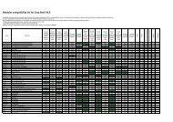
b) PV module connected in series should have similar current. Modules must not be<br />
connected together to create a voltage higher than the permitted system<br />
voltage(1000VDC), as reference the maximum number of modules in series (N)<br />
can be easily calculated by dividing the Maximum System Voltage of the modules<br />
by the respective Voc value of the module. Any more please always take into<br />
consideration the variation of the voltage under different temperatures, the Voc of<br />
the modules will be rise when the temperature drops.<br />
For example: with JKM190M-72 modules (Max. System voltage is 1000V) the<br />
maximum series modules configuration number should NEVER can exceed N= 22<br />
(1000V/45.2V = 22.1)<br />
c) PV module connect in parallel should have similar voltage. As reference the<br />
maximum number of modules in parallel (M) can be easily calculated by dividing<br />
the maximum rated current ( indicated in the electrical specification below) by Isc<br />
value of the module, and then plus 1. Any more please always take into<br />
consideration the variation of the current under different temperatures, the Isc of<br />
the modules will be rise when the temperature goes up.<br />
d) Open the connection box of the control system and connect the cabled from the PV<br />
arrays to the connection box in accordance with the installation indication of the PV<br />
control systems. The cross-sectional area and cable connector capacity must<br />
satisfy the maximum short-circuit of PV system (For a single component, we<br />
recommended the cross-sectional area of cables is 4mm 2 and the rated current of<br />
connectors is more than 10A), otherwise cables and connectors will become<br />
overheating for large current. Please pay attention: the temperature limit of cables<br />
is 85℃ and the temperature limit of connector 105℃)<br />
e) <strong>All</strong> module frames and mounting racks must be properly grounded in accordance<br />
with local and national electrical codes. Attach the equipment grounding conductor<br />
to the module frame using the hole and hardware provided. Note that a stainless<br />
steel star washer is used between the ground wire and the module frame (see<br />
picture below). This washer is used to avoid corrosion due to dissimilar metals.<br />
Tighten the screw securely.<br />
12