SMA 3300/3800 Manual - All Eco Energy
SMA 3300/3800 Manual - All Eco Energy
SMA 3300/3800 Manual - All Eco Energy

You also want an ePaper? Increase the reach of your titles
YUMPU automatically turns print PDFs into web optimized ePapers that Google loves.
PV Inverter<br />
SUNNY BOY <strong>3300</strong> / <strong>3800</strong><br />
Installation Guide<br />
SB33_38-IEN100540 | IME-SB<strong>3800</strong> | Version 4.0<br />
EN
<strong>SMA</strong> Solar Technology AG<br />
Table of Contents<br />
Table of Contents<br />
1 Notes on this <strong>Manual</strong>. . . . . . . . . . . . . . . . . . . . . . . . . . . . . . 6<br />
1.1 Area of validity . . . . . . . . . . . . . . . . . . . . . . . . . . . . . . . . . . . . . . 6<br />
1.2 Target Group . . . . . . . . . . . . . . . . . . . . . . . . . . . . . . . . . . . . . . . 6<br />
1.3 Additional Information . . . . . . . . . . . . . . . . . . . . . . . . . . . . . . . . 6<br />
1.4 Symbols Used . . . . . . . . . . . . . . . . . . . . . . . . . . . . . . . . . . . . . . . 7<br />
2 Safety . . . . . . . . . . . . . . . . . . . . . . . . . . . . . . . . . . . . . . . . . . 8<br />
2.1 Appropriate Usage. . . . . . . . . . . . . . . . . . . . . . . . . . . . . . . . . . . 8<br />
2.2 Safety Instructions . . . . . . . . . . . . . . . . . . . . . . . . . . . . . . . . . . . 10<br />
2.3 Explanation of Symbols . . . . . . . . . . . . . . . . . . . . . . . . . . . . . . 11<br />
2.3.1 Symbols on the Inverter. . . . . . . . . . . . . . . . . . . . . . . . . . . . . . . . . . . . . . . . . 11<br />
2.3.2 Symbols on the Type Label . . . . . . . . . . . . . . . . . . . . . . . . . . . . . . . . . . . . . . 11<br />
3 Unpacking. . . . . . . . . . . . . . . . . . . . . . . . . . . . . . . . . . . . . . 13<br />
3.1 Packing List . . . . . . . . . . . . . . . . . . . . . . . . . . . . . . . . . . . . . . . . 13<br />
3.2 Identifying the Inverter . . . . . . . . . . . . . . . . . . . . . . . . . . . . . . . 14<br />
4 Installation . . . . . . . . . . . . . . . . . . . . . . . . . . . . . . . . . . . . . 15<br />
4.1 Safety . . . . . . . . . . . . . . . . . . . . . . . . . . . . . . . . . . . . . . . . . . . . 15<br />
4.2 Selecting the Mounting Location. . . . . . . . . . . . . . . . . . . . . . . . 15<br />
4.3 Mounting the Inverter with Wall Mounting Bracket . . . . . . . . . 17<br />
5 Electrical Connection . . . . . . . . . . . . . . . . . . . . . . . . . . . . . 20<br />
5.1 Safety . . . . . . . . . . . . . . . . . . . . . . . . . . . . . . . . . . . . . . . . . . . . 20<br />
5.2 Overview of the Connection Area . . . . . . . . . . . . . . . . . . . . . . 20<br />
5.2.1 Exterior View . . . . . . . . . . . . . . . . . . . . . . . . . . . . . . . . . . . . . . . . . . . . . . . . . 20<br />
5.2.2 Interior View . . . . . . . . . . . . . . . . . . . . . . . . . . . . . . . . . . . . . . . . . . . . . . . . . 21<br />
5.3 Connection to the Public Grid (AC) . . . . . . . . . . . . . . . . . . . . . 22<br />
5.3.1 Conditions for the AC Connection . . . . . . . . . . . . . . . . . . . . . . . . . . . . . . . . 22<br />
5.3.2 Connecting to the Public Grid (AC) . . . . . . . . . . . . . . . . . . . . . . . . . . . . . . . 24<br />
Installation Guide SB33_38-IEN100540 3
Table of Contents<br />
<strong>SMA</strong> Solar Technology AG<br />
5.4 Setting the Display Language . . . . . . . . . . . . . . . . . . . . . . . . . . 27<br />
5.5 Connection of the PV Generator (DC) . . . . . . . . . . . . . . . . . . . 28<br />
5.5.1 Conditions for the DC Connection . . . . . . . . . . . . . . . . . . . . . . . . . . . . . . . . 28<br />
5.5.2 Assembling the DC Plug Connectors. . . . . . . . . . . . . . . . . . . . . . . . . . . . . . . 29<br />
5.5.3 Opening the DC Plug Connector . . . . . . . . . . . . . . . . . . . . . . . . . . . . . . . . . 31<br />
5.5.4 Connecting the PV Generator (DC) . . . . . . . . . . . . . . . . . . . . . . . . . . . . . . . 32<br />
5.6 Communication. . . . . . . . . . . . . . . . . . . . . . . . . . . . . . . . . . . . . 34<br />
5.7 Setting the Grid Parameters and Country Parameters . . . . . . . 35<br />
5.7.1 Setting the Installation Country . . . . . . . . . . . . . . . . . . . . . . . . . . . . . . . . . . . 35<br />
5.7.2 Setting Off-Grid Operation . . . . . . . . . . . . . . . . . . . . . . . . . . . . . . . . . . . . . . 35<br />
6 Commissioning . . . . . . . . . . . . . . . . . . . . . . . . . . . . . . . . . . 36<br />
7 Opening and Closing. . . . . . . . . . . . . . . . . . . . . . . . . . . . . 37<br />
7.1 Safety . . . . . . . . . . . . . . . . . . . . . . . . . . . . . . . . . . . . . . . . . . . . 37<br />
7.2 Opening the Inverter. . . . . . . . . . . . . . . . . . . . . . . . . . . . . . . . . 37<br />
7.3 Closing the Inverter. . . . . . . . . . . . . . . . . . . . . . . . . . . . . . . . . . 39<br />
8 Maintenance and Cleaning. . . . . . . . . . . . . . . . . . . . . . . . 41<br />
8.1 Checking Heat Dissipation . . . . . . . . . . . . . . . . . . . . . . . . . . . . 41<br />
8.1.1 Cleaning the Fan. . . . . . . . . . . . . . . . . . . . . . . . . . . . . . . . . . . . . . . . . . . . . . 41<br />
8.1.2 Checking the Fans. . . . . . . . . . . . . . . . . . . . . . . . . . . . . . . . . . . . . . . . . . . . . 42<br />
8.1.3 Cleaning the Air Grills. . . . . . . . . . . . . . . . . . . . . . . . . . . . . . . . . . . . . . . . . . 44<br />
8.2 Checking the Electronic Solar Switch for Wear . . . . . . . . . . . . 45<br />
9 Troubleshooting . . . . . . . . . . . . . . . . . . . . . . . . . . . . . . . . . 46<br />
9.1 Blink Codes. . . . . . . . . . . . . . . . . . . . . . . . . . . . . . . . . . . . . . . . 46<br />
9.2 Error Messages. . . . . . . . . . . . . . . . . . . . . . . . . . . . . . . . . . . . . 47<br />
9.3 Red LED is Glowing Continuously. . . . . . . . . . . . . . . . . . . . . . . 52<br />
9.3.1 Checking the PV Generator for a Ground Fault . . . . . . . . . . . . . . . . . . . . . . 52<br />
9.3.2 Checking the Function of the Varistors . . . . . . . . . . . . . . . . . . . . . . . . . . . . . 53<br />
10 Decommissioning . . . . . . . . . . . . . . . . . . . . . . . . . . . . . . . . 56<br />
4 SB33_38-IEN100540 Installation Guide
<strong>SMA</strong> Solar Technology AG<br />
Table of Contents<br />
10.1 Dismantling the Inverter. . . . . . . . . . . . . . . . . . . . . . . . . . . . . . . 56<br />
10.2 Packing the Inverter. . . . . . . . . . . . . . . . . . . . . . . . . . . . . . . . . . 58<br />
10.3 Storing the Inverter . . . . . . . . . . . . . . . . . . . . . . . . . . . . . . . . . . 58<br />
10.4 Disposing of the Inverter . . . . . . . . . . . . . . . . . . . . . . . . . . . . . . 58<br />
11 Technical Data . . . . . . . . . . . . . . . . . . . . . . . . . . . . . . . . . . 59<br />
11.1 Sunny Boy <strong>3300</strong> . . . . . . . . . . . . . . . . . . . . . . . . . . . . . . . . . . . 59<br />
11.2 Sunny Boy <strong>3800</strong> . . . . . . . . . . . . . . . . . . . . . . . . . . . . . . . . . . . 62<br />
12 Accessories . . . . . . . . . . . . . . . . . . . . . . . . . . . . . . . . . . . . . 65<br />
13 Contact . . . . . . . . . . . . . . . . . . . . . . . . . . . . . . . . . . . . . . . . 66<br />
Installation Guide SB33_38-IEN100540 5
Notes on this <strong>Manual</strong><br />
<strong>SMA</strong> Solar Technology AG<br />
1 Notes on this <strong>Manual</strong><br />
1.1 Area of validity<br />
This manual describes the assembly, installation, commissioning and maintenance of the following<br />
<strong>SMA</strong> inverters:<br />
• Sunny Boy <strong>3300</strong> (SB <strong>3300</strong>) from firmware version GRX33_2.94/2.94,<br />
• Sunny Boy <strong>3800</strong> (SB <strong>3800</strong>) from firmware version GRX38_2.94/2.94.<br />
The firmware version will be indicated in the display once you have commissioned the inverter.<br />
Store this manual where it can be accessed at all times.<br />
1.2 Target Group<br />
This manual is for qualified personnel. The tasks described in this manual may be performed by<br />
qualified personnel only.<br />
1.3 Additional Information<br />
You will find further information on special topics such as designing a line circuit breaker or the<br />
description of the operating parameters in the download area at www.<strong>SMA</strong>.de/en.<br />
Refer to the user manual for detailed information on operating the inverter.<br />
6 SB33_38-IEN100540 Installation Guide
<strong>SMA</strong> Solar Technology AG<br />
Notes on this <strong>Manual</strong><br />
1.4 Symbols Used<br />
The following types of safety instructions and general information appear in this document as<br />
described below:<br />
DANGER!<br />
DANGER indicates a hazardous situation which, if not avoided, will result in death or<br />
serious injury.<br />
WARNING!<br />
WARNING indicates a hazardous situation which, if not avoided, could result in death or<br />
serious injury.<br />
CAUTION!<br />
CAUTION indicates a hazardous situation which, if not avoided, could result in minor or<br />
moderate injury.<br />
NOTICE!<br />
NOTICE indicates a situation that can result in property damage, if not avoided.<br />
Information<br />
Information provides tips that are valuable for the optimal installation and operation of<br />
your product.<br />
☑<br />
This symbol indicates an outcome.<br />
Installation Guide SB33_38-IEN100540 7
Safety<br />
<strong>SMA</strong> Solar Technology AG<br />
2 Safety<br />
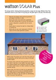
2.1 Appropriate Usage<br />
The Sunny Boy is a PV inverter, which converts the DC current of the PV generator to AC current and<br />
feeds it into the public grid.<br />
Principle of a PV system with this Sunny Boy<br />
The Sunny Boy may only be operated with PV generators (modules and cabling) of protection class<br />
II. Do not connect any sources of energy other than PV modules to the Sunny Boy.<br />
When designing the PV system, ensure that the values comply with the permitted operating range of<br />
all components at all times. The free design program "Sunny Design"<br />
(www.<strong>SMA</strong>.de/en/SunnyDesign) will assist you. The manufacturer of the PV modules must have<br />
approved the modules for use with this Sunny Boy device. You must also ensure that all measures<br />
recommended by the module manufacturer for long-term maintenance of the module properties are<br />
taken (see also Technical Information "Module Technology" in the download area of<br />
www.<strong>SMA</strong>.de/en).<br />
Do not use the Sunny Boy for purposes other than those described here. Alternative uses,<br />
modifications to the Sunny Boy or the installation of components not expressly recommended or sold<br />
by <strong>SMA</strong> Solar Technology AG void the warranty claims and operation permission.<br />
8 SB33_38-IEN100540 Installation Guide
<strong>SMA</strong> Solar Technology AG<br />
Safety<br />
Certified countries<br />
The Sunny Boy <strong>3300</strong> / <strong>3800</strong> (with according configuration) fulfill the requirements specified in the<br />
following standards and directives (dated: 02/2010):<br />
• VDE 0126-1-1 (02.2006)<br />
• RD 1663/2000 (2000)<br />
• G83/1 (09.2003)<br />
• CER/06/190 (10.2006)<br />
• E 2750 (11.2004)<br />
• PPC (06.2006)<br />
• EN 50438 (12.2007)<br />
• C10/C11 (08.2003)<br />
• DK 5940 Ed.2.2 (02.2006) (only applies for SB <strong>3300</strong>-IT/ <strong>3800</strong>-IT)<br />
• AS4777 (2005)<br />
• IEC utility meeting 216<br />
<strong>SMA</strong> Solar Technology AG can preset special grid parameters for other countries / installation<br />
locations according to customer requests after evaluation by <strong>SMA</strong> Solar Technology AG. You can<br />
make later modifications yourself by changing software parameters with respective communication<br />
products (e.g. Sunny Data Control or Sunny Explorer). See section 5.7 ”Setting the Grid Parameters<br />
and Country Parameters” (page 35). To change the grid-relevant parameters, you need a personal<br />
access code, the so-called <strong>SMA</strong> grid guard code. The application form for the personal access code<br />
can be found in the download area at www.<strong>SMA</strong>.de/en in the category "Data Sheet" of the<br />
respective inverter.<br />
Installation Guide SB33_38-IEN100540 9
Safety<br />
<strong>SMA</strong> Solar Technology AG<br />
2.2 Safety Instructions<br />
DANGER!<br />
Danger to life due to high voltages in the inverter!<br />
• <strong>All</strong> work on the inverter may be carried out by qualified personnel only.<br />
• The appliance is not to be used by children or persons with reduced physical, sensory<br />
or mental capabilities, or lack of experience and knowledge, unless they have been<br />
given supervision or instruction.<br />
• Children should be supervised to ensure that they do not play with the appliance.<br />
CAUTION!<br />
Danger of burn injuries due to hot enclosure parts!<br />
• Do not touch the inverter's enclosure during operation.<br />
NOTICE!<br />
Dust and water in the inverter can damage it!<br />
Once the Electronic Solar Switch has been pulled out, the inverter only provides protection<br />
rating IP21. It is then no longer protected against dust and water! In order to keep the<br />
protection rating IP65 during temporary decommissioning, proceed as follows:<br />
• Release and remove all DC plug connectors.<br />
• Open all DC plug connectors and remove the cables.<br />
• Close all DC inputs with the corresponding DC plug connectors and the sealing plugs<br />
provided.<br />
• Firmly attach the Electronic Solar Switch again.<br />
Grounding the PV generator<br />
Comply with the local requirements for grounding the modules and the PV generator. <strong>SMA</strong><br />
Solar Technology AG recommends connecting the generator frame and other electricity<br />
conducting surfaces so that there is continuous conduction and to ground them in order to<br />
achieve maximum protection of the system and personnel.<br />
10 SB33_38-IEN100540 Installation Guide
<strong>SMA</strong> Solar Technology AG<br />
Safety<br />
2.3 Explanation of Symbols<br />
This section gives an explanation of all the symbols shown on the inverter and on the type label.<br />
2.3.1 Symbols on the Inverter<br />
Symbol<br />
Explanation<br />
Operation Display.<br />
Shows the operating status of the inverter.<br />
Ground fault or varistor defective.<br />
Read section 9.3 ”Red LED is Glowing Continuously” (page 52).<br />
Fault or disturbance.<br />
Read section 9 ”Troubleshooting” (page 46).<br />
Tap to switch on the display light and switch to the next message.<br />
2.3.2 Symbols on the Type Label<br />
DC circuit breaker Electronic Solar Switch (ESS)<br />
• If the Electronic Solar Switch connects, then the DC circuit is<br />
completed.<br />
• To interrupt the DC circuit and disconnect the inverter securely<br />
under load, you have to first pull out the Electronic Solar Switch<br />
and then remove all DC plug connectors , as described in section<br />
7.2 ”Opening the Inverter” (page 37).<br />
Symbol<br />
Explanation<br />
Beware of dangerous electrical voltage.<br />
The inverter operates at high voltages. <strong>All</strong> work on the inverter may be<br />
carried out by qualified personnel only.<br />
Beware of hot surface.<br />
The inverter can become hot during operation. Avoid contact during<br />
operation.<br />
Observe all documentation accompanying the inverter.<br />
Installation Guide SB33_38-IEN100540 11
Safety<br />
<strong>SMA</strong> Solar Technology AG<br />
Symbol<br />
Explanation<br />
The inverter must not be disposed of with the household waste. For further<br />
information on disposal, see section 10.4 ”Disposing of the Inverter”<br />
(page 58).<br />
CE mark.<br />
The inverter complies with the requirements of the applicable EC<br />
guidelines.<br />
The inverter has a transformer.<br />
Direct Current (DC)<br />
Alternating Current (AC)<br />
Protection rating IP65.<br />
The inverter is protected against penetration by dust particles and water<br />
jets from any angle.<br />
RAL quality mark for solar products.<br />
The inverter complies with the requirements of the German Institute for<br />
Quality Assurance and Labeling.<br />
12 SB33_38-IEN100540 Installation Guide
<strong>SMA</strong> Solar Technology AG<br />
Unpacking<br />
3 Unpacking<br />
3.1 Packing List<br />
Check the delivery for completeness and for visible external damage, such as cracks in the enclosure<br />
or in the display. Contact your dealer if anything is damaged or missing.<br />
Object Number Description<br />
A 1 Sunny Boy<br />
B 1 Wall mounting bracket (rear panel)<br />
C 2 Air grills (1 x right / 1 x left)<br />
D 1 Electronic Solar Switch (ESS)<br />
E 5 Sealing plug for wall mounting bracket (sealing)<br />
F 2 Cylinder head screws and M6 contact washers<br />
G 1 Jumper for communication / fan test<br />
H 1 AC coupling socket: socket unit, protective cap for socket unit, threaded<br />
sleeve, sealing ring, clamping nut.<br />
I 6 Sealing plugs for DC plug connectors<br />
K 6 DC plug connectors (3 x positive / 3 x negative)<br />
L 1 Installation guide<br />
M 1 User manual<br />
N 1 Document set<br />
O 1 Supplement with the factory settings of the inverter<br />
Installation Guide SB33_38-IEN100540 13
Unpacking<br />
<strong>SMA</strong> Solar Technology AG<br />
3.2 Identifying the Inverter<br />
You can identify the inverter by the type label. The type label is on the right side of the enclosure.<br />
The serial number (Serial No.) and the type (Type / Model) of the product, as well as device-specific<br />
characteristics are specified on the type label.<br />
14 SB33_38-IEN100540 Installation Guide
<strong>SMA</strong> Solar Technology AG<br />
Installation<br />
4 Installation<br />
4.1 Safety<br />
DANGER!<br />
Danger to life due to fire or explosion!<br />
Despite careful construction, electrical devices can cause fires.<br />
• Do not mount the inverter on flammable construction materials.<br />
• Do not install the inverter in areas where highly flammable materials are stored.<br />
• Do not install inverters in areas with a risk of explosion.<br />
CAUTION!<br />
Danger of burn injuries due to hot enclosure parts!<br />
• Mount the inverter in such a way that it cannot be touched inadvertently during<br />
operation.<br />
CAUTION!<br />
Risk of injury due to the heavy weight of the inverter!<br />
• Take the inverter's weight of approx. 38 kg into account for mounting.<br />
4.2 Selecting the Mounting Location<br />
Consider the following points when selecting where to install:<br />
• The installation method and location must be suitable for the inverter's weight and dimensions<br />
(see section 11 ”Technical Data” (page 59)).<br />
• Mount on a solid surface.<br />
• It must be possible to access the installation location freely and safely at all times without the<br />
need for additional tools such as scaffolding or lifting platforms. Service actions are otherwise<br />
limited.<br />
• Vertical installation or tilted backward by max. 45°.<br />
• The connection area must point downward.<br />
Installation Guide SB33_38-IEN100540 15
Installation<br />
<strong>SMA</strong> Solar Technology AG<br />
• Never install the device with a forward tilt.<br />
• Do not install horizontally.<br />
• Install at eye level in order to allow the operating status to be read at all times.<br />
• The inverter must be easy to remove from the mounting location at any time.<br />
• The ambient temperature should be below 40 °C to ensure optimal operation.<br />
• Do not expose the inverter to direct sunlight to avoid a power reduction due to excessive<br />
heating.<br />
• In living areas, do not mount the unit on plasterboard walls or similar in order to avoid audible<br />
vibrations. The inverter can make noises when in use which may be perceived as a nuisance in<br />
a living area.<br />
• Observe the minimum clearances to walls, other<br />
inverters or objects as shown in the diagram in<br />
order to guarantee sufficient heat dissipation and to<br />
have enough space for removing the Electronic<br />
Solar Switch.<br />
Multiple inverters installed in areas with high ambient temperatures<br />
If necessary, increase the clearances between the individual inverters. In addition, make<br />
sure there is enough ventilation to ensure sufficient cooling of the inverters.<br />
16 SB33_38-IEN100540 Installation Guide
<strong>SMA</strong> Solar Technology AG<br />
Installation<br />
4.3 Mounting the Inverter with Wall Mounting Bracket<br />
CAUTION!<br />
Risk of injury due to the heavy weight of the inverter!<br />
• Remember that the inverter weighs approx. 38 kg.<br />
1. Use the wall mounting bracket as a drilling template and mark the positions of the drill holes.<br />
Mounting material<br />
When mounting the bracket, use fastening material suitable for the material<br />
2. Fill in holes that are not required in the wall mounting bracket using the sealing plugs. Insert the<br />
sealing plugs into the wall mounting bracket from the outside (the side that will later be placed<br />
against the wall).<br />
Installation Guide SB33_38-IEN100540 17
Installation<br />
<strong>SMA</strong> Solar Technology AG<br />
3. Attach the wall mounting bracket to the wall using<br />
appropriate screws and washers.<br />
4. Mount the inverter with the upper fastening plates<br />
on the wall mounting bracket so that both plates on<br />
the upper edge of the bracket pass through the<br />
cutouts on the inverter.<br />
5. Visual inspection: The inverter is only correctly<br />
mounted when both rear panel mounting plates<br />
slightly protrude through the cutouts.<br />
6. Secure the inverter in position by screwing the<br />
supplied M6 contact screw, located on the<br />
underside of the enclosure. Use the contact<br />
washers provided with the toothing against the<br />
enclosure. Tighten the screw with a torque of<br />
approximately 5 Nm.<br />
18 SB33_38-IEN100540 Installation Guide
<strong>SMA</strong> Solar Technology AG<br />
Installation<br />
7. Check to ensure the inverter is firmly secured. The wall mounting bracket is designed so that the<br />
inverter tilts backward slightly on a perfectly vertical wall.<br />
8. Attach the air grills provided to the inverter. To help<br />
you identify the sides, "links/left" or "rechts/right" is<br />
printed on the inside of the air grills.<br />
☑<br />
The inverter is now mounted.<br />
Installation Guide SB33_38-IEN100540 19
Electrical Connection<br />
<strong>SMA</strong> Solar Technology AG<br />
5 Electrical Connection<br />
5.1 Safety<br />
NOTICE!<br />
Electrostatic discharge can damage the inverter!<br />
Internal components of the inverter can be irreparably damaged by static discharge.<br />
• Before you touch a component inside the inverter, ground yourself by touching a<br />
grounded object.<br />
5.2 Overview of the Connection Area<br />
5.2.1 Exterior View<br />
The following figure shows the assignment of the individual connection areas on the bottom of the<br />
inverter.<br />
Object Description<br />
A<br />
Enclosure openings for communication (with dummy plugs)<br />
B<br />
DC plug connectors for connecting the PV strings<br />
C<br />
Socket for the connection of the Electronic Solar Switch (ESS) DC load<br />
disconnection unit<br />
D<br />
AC socket for grid connection<br />
20 SB33_38-IEN100540 Installation Guide
<strong>SMA</strong> Solar Technology AG<br />
Electrical Connection<br />
5.2.2 Interior View<br />
The following illustration shows the various components and connection areas of the open inverter.<br />
Object Description<br />
A Slot for communication<br />
B Display<br />
C Jumper slot for fan test<br />
D Operating status LEDs<br />
E Tab for grounding the cable shield with line-conducted communication<br />
F AC socket for grid connection<br />
G DC plug connectors for connecting the PV strings<br />
H Electronic Solar Switch (ESS) socket<br />
I Enclosure opening with sealing plugs for communication<br />
K Varistors<br />
L Communication connector<br />
M Jumper slot for communication<br />
Installation Guide SB33_38-IEN100540 21
Electrical Connection<br />
<strong>SMA</strong> Solar Technology AG<br />
5.3 Connection to the Public Grid (AC)<br />
5.3.1 Conditions for the AC Connection<br />
Connection requirements of the utility operator<br />
Always observe the connection requirements of your utility operator!<br />
Cable Sizing<br />
For optimum operation of the inverter, the grid impedance of the AC cable must not exceed 1 Ohm.<br />
This is necessary, amongst other things, for the correct operation of the inverter.<br />
The conductor cross-section should be dimensioned in a way that output losses do not exceed 1 % at<br />
nominal power. Use "Sunny Design" (www.<strong>SMA</strong>.de/en/SunnyDesign) for this.<br />
The maximum cable lengths are shown in the following table. Do not exceed the maximum cable<br />
length.<br />
Conductor cross-section<br />
Maximum cable length<br />
SB <strong>3300</strong> SB <strong>3800</strong><br />
4 mm² 18.5 m 16 m<br />
The conductor cross-sectional area required in individual cases depends on the following factors:<br />
• Ambient temperature,<br />
• Routing method,<br />
• UV resistance,<br />
• Conduction losses,<br />
• Valid installation guidelines of the respective country (of the installation location).<br />
Cable Requirements<br />
Position Description Value<br />
A External diameter 6 mm ... 14 mm<br />
B Conductor cross-section 4 mm²<br />
C Strip insulation 8 mm<br />
22 SB33_38-IEN100540 Installation Guide
<strong>SMA</strong> Solar Technology AG<br />
Electrical Connection<br />
Load Disconnection Unit<br />
You must install a separate line circuit breaker for each inverter in order to ensure that the inverter<br />
can be securely disconnected under load. The maximal permissible fuse protection is located in<br />
section 11 ”Technical Data” (page 59).<br />
Detailed information and examples for the rating of a line circuit breaker can be found in the Technical<br />
Information "Line Circuit Breaker" in the <strong>SMA</strong> Solar Technology AG download area at<br />
www.<strong>SMA</strong>.de/en.<br />
DANGER!<br />
Danger to life due to fire!<br />
When more than one inverter is connected to the same line circuit breaker, the protective<br />
function of the line circuit breaker is no longer guaranteed. It can result in a cable fire or<br />
the destruction of the inverter.<br />
• Never connect several inverters to a single line circuit breaker.<br />
• Comply with the maximum permissible fuse protection of the inverter when selecting<br />
the circuit breaker.<br />
DANGER!<br />
Danger to life due to fire!<br />
When a generator (inverter) and a consumer are connected to the same line circuit<br />
breaker, the protective function of the line circuit breaker is no longer guaranteed. The<br />
current from the inverter and the grid can accumulate to overcurrent which is not detected<br />
by the line circuit breaker.<br />
• Never connect loads between the<br />
inverter and the line circuit breaker<br />
without protection.<br />
• Always protect loads separately.<br />
NOTICE!<br />
Damage to the inverter by using screw type fuse elements as a load<br />
disconnection unit!<br />
A screw type fuse element, e.g. D system (Diazed) or D0 system (Neozed) is not a load<br />
disconnection device, and thus may not be used as a load disconnection unit. A screw type<br />
fuse element is only used as cable protection.<br />
When disconnecting under load using a screw type fuse element, the inverter can be<br />
damaged.<br />
• Use only a load disconnecting switch or a line circuit breaker as a load disconnecting<br />
unit.<br />
Installation Guide SB33_38-IEN100540 23
Electrical Connection<br />
<strong>SMA</strong> Solar Technology AG<br />
5.3.2 Connecting to the Public Grid (AC)<br />
Overview AC connection socket<br />
Object Description<br />
A<br />
Protective cap for socket element<br />
B<br />
Socket element<br />
C<br />
Threaded sleeve with sealing ring for cable diameters of 10 mm to 14 mm<br />
D<br />
Sealing ring for cable diameters of 6 mm to 10 mm<br />
E<br />
Clamping nut<br />
Procedure<br />
1. Check the grid voltage and compare with "V AC nom " on the type label.<br />
The exact operating range of the inverter is specified in the operating parameters. The<br />
corresponding document is available in the download area at www.<strong>SMA</strong>.de/en in the<br />
category "Technical Description" of the respective inverter.<br />
2. Disconnect the line circuit breaker and secure it to prevent it from being reactivated.<br />
3. If necessary, exchange the sealing ring of the threaded sleeve with the sealing ring provided.<br />
– Pull the sealing ring out of the threaded sleeve.<br />
– Insert the smaller sealing ring.<br />
4. Thread the clamping nut (E) over the AC cable.<br />
24 SB33_38-IEN100540 Installation Guide
<strong>SMA</strong> Solar Technology AG<br />
Electrical Connection<br />
5. Thread the threaded sleeve (C) with sealing ring over the AC cable.<br />
6. Bend the AC cable. The bend radius must be at<br />
least four times the cable diameter.<br />
7. Shorten the cable.<br />
8. Shorten phase L and neutral conductor<br />
N 4 to 5 mm.<br />
9. Insert the PE protective conductor (green-yellow)<br />
into the screw terminal with the earth sign on the<br />
socket element and tighten the screw. The PE<br />
protective conductor must be longer than the<br />
connection wires of N and L.<br />
10. Insert the neutral conductor N (blue) in the screw<br />
terminal N on the socket element and tighten the<br />
screw.<br />
11. Insert phase L (brown or black) into the screw<br />
terminal L on the socket element and tighten the<br />
screw.<br />
12. Make sure the wires are securely connected.<br />
13. Push the threaded sleeve (C) onto the socket element (B) until it audibly snaps into place.<br />
Installation Guide SB33_38-IEN100540 25
Electrical Connection<br />
<strong>SMA</strong> Solar Technology AG<br />
14. Screw the clamping nut (E) tightly onto the threaded sleeve (C). The clamping nut serves to seal<br />
and relieve strain.<br />
☑ The AC connection socket has been screwed together.<br />
15. Close the socket element with the protective cap provided, if the inverter has not yet been<br />
connected.<br />
16. Insert the AC connection socket into the AC socket<br />
on the inverter. Remove the protective cap<br />
beforehand as required.<br />
A<br />
☑<br />
The AC cable is now connected to the inverter.<br />
DANGER!<br />
Danger to life due to high voltages in the inverter!<br />
• Do not switch on the line circuit breaker until the PV generator has been connected<br />
and the inverter is securely closed.<br />
26 SB33_38-IEN100540 Installation Guide
<strong>SMA</strong> Solar Technology AG<br />
Electrical Connection<br />
5.4 Setting the Display Language<br />
You can set the language of the display using the switches on the underside of the display assemblies<br />
inside the inverter.<br />
Procedure<br />
1. Open the inverter as described in section 7.2 ”Opening the Inverter” (page 37).<br />
2. Set the switches for the required language, as<br />
shown below.<br />
Language Switch S2 Switch S1<br />
German B B<br />
English B A<br />
French A B<br />
Spanish A A<br />
3. Close the inverter as described in section 7.2 "Closing Sunny Boy" (page 33).<br />
☑ The display language is now set.<br />
Installation Guide SB33_38-IEN100540 27
Electrical Connection<br />
<strong>SMA</strong> Solar Technology AG<br />
5.5 Connection of the PV Generator (DC)<br />
5.5.1 Conditions for the DC Connection<br />
Use of Adaptors<br />
Adaptors (branch connectors) are not to be visible or freely accessible in the immediate<br />
surrounding of the inverter.<br />
• The DC current flow may not be interrupted via adaptors.<br />
• Disconnect the inverter, as described in section 7.2 ”Opening the Inverter”<br />
(page 37).<br />
• Requirements for the PV modules of the connected strings:<br />
– Same type<br />
– Same number<br />
– Identical alignment<br />
– Identical tilt<br />
• The connection cables of the PV modules must be equipped with plug connectors. You will find<br />
the necessary DC plug connectors for the DC connection in the delivery.<br />
• The following limiting values at the DC input of the inverter may not be exceeded:<br />
Maximum input voltage<br />
Maximum input current<br />
500 V (DC) 20 A (DC)<br />
DANGER!<br />
Risk of lethal electric shock or fire!<br />
The maximum possible input current per string is limited by the plug connectors used. If the<br />
plug connectors are overloaded, an electric arc may occur and there is a risk of fire.<br />
• Ensure that the input current for each string does not exceed the maximum flow<br />
current of the plug connectors used.<br />
28 SB33_38-IEN100540 Installation Guide
<strong>SMA</strong> Solar Technology AG<br />
Electrical Connection<br />
5.5.2 Assembling the DC Plug Connectors<br />
The connection cables of the PV modules must be equipped with the DC plug connectors provided for<br />
connecting the inverter.<br />
To assemble the DC plug connectors, proceed as follows: Make sure the plug connectors have the<br />
correct polarity. The DC plug connectors have the symbols "+" and " − ".<br />
Cable Requirements<br />
• Use a PV1-F cable.<br />
Procedure<br />
1. Insert the stripped cable into the plug connector as<br />
far as it will go.<br />
2. Press the clamping bracket down until it audibly<br />
snaps into place.<br />
3. Ensure the cable is correctly in place.<br />
Result<br />
☑ If the conductor is visible in the hollow<br />
cavity of the clamp, the cable is in the<br />
correct position.<br />
Action<br />
• Proceed to step 4.<br />
Installation Guide SB33_38-IEN100540 29
Electrical Connection<br />
<strong>SMA</strong> Solar Technology AG<br />
Result<br />
☑ If the conductor is not visible in the hollow<br />
cavity of the clamp, the cable is not in the<br />
correct position.<br />
Action<br />
• Loosen the clamping bracket with the help<br />
of a screwdriver.<br />
4. Push the threaded joint to the thread and screw into place.<br />
• Remove the cable and start again from<br />
step 1.<br />
☑<br />
The DC plug connectors are now assembled and can be connected to the inverter as described<br />
in section 5.5 ”Connection of the PV Generator (DC)” (page 28).<br />
30 SB33_38-IEN100540 Installation Guide
<strong>SMA</strong> Solar Technology AG<br />
Electrical Connection<br />
5.5.3 Opening the DC Plug Connector<br />
1. Screw the threaded joint off.<br />
2. To release the plug connector, slot a screw driver<br />
into the side catch mechanism and lever out.<br />
3. Carefully pull apart the DC plug connector.<br />
4. Loosen the clamping bracket with the help of a<br />
screwdriver.<br />
5. Remove cable.<br />
☑<br />
The cable is removed from the DC plug connector.<br />
Installation Guide SB33_38-IEN100540 31
Electrical Connection<br />
<strong>SMA</strong> Solar Technology AG<br />
5.5.4 Connecting the PV Generator (DC)<br />
DANGER!<br />
Danger to life due to high voltages in the inverter!<br />
• Before connecting the PV generator, ensure that the line circuit breaker is switched<br />
off and that it cannot be reactivated.<br />
NOTICE!<br />
Excessive voltages can destroy the measuring device!<br />
• Only use measuring devices with a DC input voltage range up to at least 600 V.<br />
1. Disconnect the line circuit breaker and secure it to prevent it from being reactivated.<br />
2. Pull the Electronic Solar Switch downward, slightly<br />
toward the wall.<br />
3. Check the connection cables of the PV modules for<br />
correct polarity and that the maximum input voltage<br />
of the inverter is not exceeded.<br />
With an ambient temperature over 10 °C, the<br />
open circuit voltage of the PV modules should not<br />
exceed 90 % of the maximum input voltage of the<br />
inverter. Otherwise, check the system design and<br />
the PV module connection. At lower ambient<br />
temperatures, the maximum input voltage of the<br />
inverter can otherwise be exceeded.<br />
NOTICE!<br />
Exceeding the maximum input voltage can destroy the inverter!<br />
If the voltage of the PV modules exceeds the maximum input voltage of the inverter, it can<br />
be destroyed by the overvoltage. <strong>All</strong> warranty claims become void.<br />
• Do not connect strings with an open circuit voltage greater than the maximum input<br />
voltage of the inverter.<br />
• Check the system design.<br />
4. Check the strings for ground faults, as described in section 9.3.1 ”Checking the PV Generator<br />
for a Ground Fault” (page 52).<br />
32 SB33_38-IEN100540 Installation Guide
<strong>SMA</strong> Solar Technology AG<br />
Electrical Connection<br />
NOTICE!<br />
Excessive currents can damage the inverter!<br />
• The maximum current per DC connector plug may not exceed 16 A.<br />
DANGER!<br />
Risk of lethal electric shock!<br />
• Do not connect strings with ground faults.<br />
• First, rectify the ground fault in the respective string.<br />
5. Check the DC plug connectors for correct polarity and connect them.<br />
To release the DC plug connectors, see section 7.2 ”Opening the Inverter” (page 37).<br />
6. To create the sealing on the inverter, all the DC<br />
inputs have to be closed as follows:<br />
– Insert the sealing plugs provided into the DC<br />
plug connectors that are not required.<br />
Do not insert the sealing plugs into the DC<br />
inputs on the inverter.<br />
– Insert the DC plug connectors with sealing plugs<br />
into the corresponding DC inputs on the inverter.<br />
Installation Guide SB33_38-IEN100540 33
Electrical Connection<br />
<strong>SMA</strong> Solar Technology AG<br />
7. Check the Electronic Solar Switch for wear, as<br />
described in section 8.2 ”Checking the Electronic<br />
Solar Switch for Wear” (page 45) and attach it<br />
firmly.<br />
NOTICE!<br />
The Electronic Solar Switch can be damaged if it is inserted incorrectly!<br />
The Electric Solar Switch can be damaged by high voltages if it has not been attached<br />
properly.<br />
• Do not tighten the screw inside the handle.<br />
• Insert the handle of the Electronic Solar Switch securely in the socket on the underside<br />
of the enclosure until you hear an audible click.<br />
• Check the handle of the Electronic Solar Switch is securely connected.<br />
☑<br />
The PV generator is now connected.<br />
5.6 Communication<br />
The inverter is equipped with a slot for communication interfaces in order to communicate with special<br />
data acquisition devices (e.g. Sunny WebBox) or a PC with corresponding software (e.g. Sunny Data<br />
Control or Sunny Explorer).<br />
See the respective communication interface manual for a detailed wiring diagram and an installation<br />
description for the interface.<br />
34 SB33_38-IEN100540 Installation Guide
<strong>SMA</strong> Solar Technology AG<br />
Electrical Connection<br />
5.7 Setting the Grid Parameters and Country Parameters<br />
Changing grid-relevant parameters and country parameters<br />
To change the grid-relevant parameters, you need a personal access code, the so-called<br />
<strong>SMA</strong> grid guard code. The application form for the personal access code can be found in<br />
the download area at www.<strong>SMA</strong>.de/en in the category "Data Sheet" of the respective<br />
inverter.<br />
Ensure that you discuss the changes to these parameters with your utility operator.<br />
A detailed description of the operating parameter for the inverter is available in the download area<br />
at www.<strong>SMA</strong>.de/en in the category "Technical Description" of the respective inverter.<br />
5.7.1 Setting the Installation Country<br />
Using the "Default" parameter you can set the installation country and/or the grid connection<br />
standard valid for the country via a communication device (e.g. Sunny WebBox) or a PC with<br />
appropriate software (e.g. Sunny Data Control or Sunny Explorer). This, however, is only required if<br />
the inverter was originally ordered for another country. You can see the standard to which the inverter<br />
was set upon delivery on the type label and the enclosed data sheet with the factory settings.<br />
5.7.2 Setting Off-Grid Operation<br />
To operate the inverter in a Sunny Island system, you must set the inverter via the "Default" parameter<br />
to off-grid ("OFF-Grid") operation.<br />
You have several possibilities to set the inverter to off-grid operation:<br />
• Setting via Sunny WebBox<br />
or<br />
• Setting via Sunny Data Control or Sunny Explorer<br />
DANGER!<br />
Danger to life due to high voltages if there is an outage of the public grid.<br />
If you set the inverter to off-grid operation, it does not fulfill any country-specific standards<br />
and regulations. Therefore if there is an outage of the public grid there is a danger of back<br />
feed.<br />
• Never operate the inverter directly on the public grid when set to off-grid operation.<br />
Installation Guide SB33_38-IEN100540 35
Commissioning<br />
<strong>SMA</strong> Solar Technology AG<br />
6 Commissioning<br />
1. Check the following requirements before commissioning:<br />
– Ensure the inverter is firmly secured<br />
– Correct connection of the AC cable (grid)<br />
– Full connection of the DC cables (PV strings)<br />
– DC inputs that are not needed are closed with the corresponding DC plug connectors and<br />
sealing plugs.<br />
– The enclosure lid is securely screwed in place<br />
– The Electronic Solar Switch (ESS) is securely plugged<br />
– The line circuit breaker is laid out correctly<br />
2. Switch on the line circuit breaker.<br />
☑ Green LED glows: commissioning has been successful.<br />
or<br />
☑ Green LED flashes when there is insufficient radiation: network connection conditions have<br />
not yet been yet reached. Wait for sufficient radiation.<br />
or<br />
☑ Red or yellow LED is glowing or flashing: there has been an error. Proceed to step 3.<br />
A Green LED In operation<br />
B Red LED Ground fault or varistor<br />
defective<br />
C Yellow LED Disturbance<br />
3. Read section 9 ”Troubleshooting” (page 46) and if necessary, eliminate the disturbance.<br />
36 SB33_38-IEN100540 Installation Guide
<strong>SMA</strong> Solar Technology AG<br />
Opening and Closing<br />
7 Opening and Closing<br />
7.1 Safety<br />
DANGER!<br />
Risk of lethal electric shock!<br />
Pay attention to the following points before opening the inverter:<br />
• Ensure that there are no hazardous voltages present on the AC side.<br />
• Ensure that there are no hazardous currents or voltages present on the DC side.<br />
NOTICE!<br />
Static discharges can damage the inverter!<br />
Internal components of the inverter can be irreparably damaged by electrostatic<br />
discharge.<br />
• Ground yourself before touching a component.<br />
7.2 Opening the Inverter<br />
1. Disconnect the line circuit breaker and secure it to prevent it from being reactivated.<br />
2. Pull the Electronic Solar Switch downward, slightly<br />
toward the wall.<br />
3. Using a current probe, ensure that there is no<br />
current to all DC cables.<br />
☑ If current is detected, check the installation!<br />
Installation Guide SB33_38-IEN100540 37
Opening and Closing<br />
<strong>SMA</strong> Solar Technology AG<br />
4. Release all DC plug connectors with the help of a<br />
screwdriver:<br />
– Insert a screwdriver into one of the side slits (1).<br />
– Lever the screwdriver upward (2) and pull out<br />
the plug connector (3).<br />
DANGER!<br />
Danger to life due to unsafe disconnection from the PV generator!<br />
A secure separation from the PV generator is only guaranteed after pulling off the<br />
Electronic Solar Switch and all DC connectors.<br />
• Remove all DC plug connectors to<br />
completely disconnect the PV generator<br />
from the inverter.<br />
5. Ensure that there is no voltage to the DC plug connectors on the inverter.<br />
☑ If there is a voltage present, check the installation!<br />
6. Pull out the AC plug.<br />
7. Check whether all LEDs and the display have gone out.<br />
38 SB33_38-IEN100540 Installation Guide
<strong>SMA</strong> Solar Technology AG<br />
Opening and Closing<br />
DANGER!<br />
Danger to life due to high voltages in the inverter!<br />
The capacitors in the inverter require 15 minutes to discharge.<br />
• Wait 15 minutes before opening the inverter.<br />
8. Loosen the screws of the enclosure lid.<br />
9. Carefully remove the lid forward.<br />
☑<br />
The inverter is open and there is no voltage present.<br />
7.3 Closing the Inverter<br />
1. Secure the lid with the 4 screws and the lock<br />
washers with the toothing facing toward the lid. The<br />
screws must be tightened with approximately 6 Nm<br />
torque to ensure the sealing of the enclosure and<br />
the grounding of the lid.<br />
DANGER!<br />
Danger to life due to live lid!<br />
The grounding of the lid is ensured by the toothed lock washers.<br />
• Fasten the lock washers for all screws with the toothing facing toward the lid.<br />
2. Check the DC plug connectors for correct polarity and connect them.<br />
To release the DC plug connectors, see section 7.2 ”Opening the Inverter” (page 37).<br />
Installation Guide SB33_38-IEN100540 39
Opening and Closing<br />
<strong>SMA</strong> Solar Technology AG<br />
3. Close all the DC inputs that are not needed as described in section 5.5.4 ”Connecting the PV<br />
Generator (DC)” (page 32) in order to create the sealing on the inverter.<br />
4. Connect the AC plug.<br />
5. Check the Electronic Solar Switch for wear, as<br />
described in section 8.2 ”Checking the Electronic<br />
Solar Switch for Wear” (page 45) and attach it<br />
firmly.<br />
NOTICE!<br />
The Electronic Solar Switch can be damaged if it is inserted incorrectly!<br />
• Do not tighten the screw inside the handle.<br />
• Insert the handle of the Electronic Solar Switch securely in the socket on the underside<br />
of the enclosure.<br />
• Check the handle of the Electronic Solar Switch is securely connected.<br />
6. Switch on the line circuit breaker.<br />
7. Check whether the inverter's display and LED<br />
display indicate normal operating mode (see<br />
section 6 ”Commissioning” (page 36)).<br />
☑<br />
The inverter is closed and in operation.<br />
40 SB33_38-IEN100540 Installation Guide
<strong>SMA</strong> Solar Technology AG<br />
Maintenance and Cleaning<br />
8 Maintenance and Cleaning<br />
Check for proper inverter operation at regular intervals. Impurities such as dust or airborne blossoms<br />
can cause heat concentration that can lead to yield losses. Also check the inverter and the cables for<br />
visible external damage. Undertake repairs if necessary.<br />
8.1 Checking Heat Dissipation<br />
You only need to check the heat dissipation of the inverter if, during a visual inspection, you notice a<br />
marked build-up in the fan grill or the inverter is increasingly observed to be in derating mode.<br />
Whether the inverter switches to derating mode depends on the ambient temperature and cooling<br />
efficiency.<br />
8.1.1 Cleaning the Fan<br />
If the fan grill is only covered in loose dust it can be cleaned with a vacuum cleaner. If you do not<br />
achieve satisfactory results with a vacuum cleaner, dismantle the fans for cleaning.<br />
Proceed as follows:<br />
1. Disconnect the inverter from both the DC and AC connections, as described in section<br />
7.2 ”Opening the Inverter” (page 37).<br />
2. Wait for the fan to stop rotating.<br />
Cleaning the Fan Grills<br />
3. Remove the fan grill:<br />
– Press the two latches on the right edge of the fan<br />
grill to the right using a screwdriver and loosen<br />
it from the bracket.<br />
– Carefully remove the fan grill.<br />
4. Clean the fan grill with a soft brush, a paint brush,<br />
a cloth or pressurized air.<br />
Cleaning the Fan<br />
5. Push the two upper plastic clips backward and the<br />
lower plastic clip forward.<br />
6. Remove the fan by pulling it slowly and carefully<br />
downward.<br />
7. Unlock and unplug the fan plug inside the inverter.<br />
The fan cables are long enough that you can lift the fan far enough out to disconnect the internal<br />
plug connector in the inverter.<br />
Installation Guide SB33_38-IEN100540 41
Maintenance and Cleaning<br />
<strong>SMA</strong> Solar Technology AG<br />
8. Remove the fan.<br />
9. Clean the fan with a soft brush, a paint brush, or a damp cloth.<br />
NOTICE!<br />
Damage to the fan through the use of pressurized air.<br />
• Under no circumstances should you use pressurized air to clean the fan. This can<br />
damage the fan.<br />
10. After cleaning, assemble everything in reverse order.<br />
11. Check the functioning of the fans as described in the following section.<br />
8.1.2 Checking the Fans<br />
You can check that the fans are working in 2 ways:<br />
• Set the "Fan Test" parameter to "1" in the installer mode using Sunny Data Control,<br />
Sunny Explorer or Sunny WebBox.<br />
or<br />
• Plug the jumper provided into the system control board.<br />
Setting Parameters<br />
1. Request the installer password from the <strong>SMA</strong> Serviceline (contact: see page 66).<br />
2. Set the "Fan Test" parameter to "1" in the installer mode.<br />
3. Check the air-flow of the fan.<br />
The inverter sucks air in from underneath and then blows it back out on the upper left side. Listen<br />
for any unusual noise that could indicate incorrect installation or that the fan is faulty.<br />
4. After checking the fan, set the "Fan Test" parameter back to 0.<br />
☑ You have finished checking the fan.<br />
42 SB33_38-IEN100540 Installation Guide
<strong>SMA</strong> Solar Technology AG<br />
Maintenance and Cleaning<br />
Plugging the Jumper<br />
The inverter recognizes the jumper only after the system has been restarted (i.e. all LEDs must have<br />
gone out before a restart).<br />
1. Open the inverter as described in section 7.2 ”Opening the Inverter” (page 37).<br />
2. Plug the jumper provided into the slot on the system control board as shown below.<br />
3. Close the inverter as described in section 7.3 ”Closing the Inverter” (page 39).<br />
4. Restart the inverter.<br />
5. Check the air-flow of the fan.<br />
The inverter sucks air in from underneath and then blows it back out on the upper left side. Listen<br />
for any unusual noise that could indicate incorrect installation or that the fan is faulty.<br />
6. Remove the jumper. Open and close the inverter as described in section 7 ”Opening and<br />
Closing” (page 37).<br />
☑ You have finished checking the fan.<br />
Installation Guide SB33_38-IEN100540 43
Maintenance and Cleaning<br />
<strong>SMA</strong> Solar Technology AG<br />
8.1.3 Cleaning the Air Grills<br />
There are fan gills on either side of the inverter. The inverter sucks air in from underneath through the<br />
fan and blows it out again on the upper left side via the air grills. For optimal heat dissipation of the<br />
inverter, you only have to clean the left air grill.<br />
Procedure<br />
1. Remove the left air grill.<br />
Insert your finger in the space between the air grill<br />
and the upper part of the enclosure and remove the<br />
air grill to the side.<br />
2. Clean the air grill with a soft brush, a paint brush,<br />
or pressurized air.<br />
3. Re-attach the air grill to the inverter.<br />
To help you identify the sides, the air grills are<br />
marked with "links/left" or "rechts/right" on the<br />
inside.<br />
☑<br />
The air grills are cleaned.<br />
NOTICE!<br />
Risk of damage to the inverter if insects enter it!<br />
• The air grills must not be removed permanently, because otherwise the device is not<br />
protected against the entrance of insects!<br />
44 SB33_38-IEN100540 Installation Guide
<strong>SMA</strong> Solar Technology AG<br />
Maintenance and Cleaning<br />
8.2 Checking the Electronic Solar Switch for Wear<br />
Check the Electronic Solar Switch for wear before plugging it in.<br />
Result<br />
☑ The metal tongues inside the connector are<br />
not damaged or discolored.<br />
Action<br />
1. Insert the handle of the Electronic Solar<br />
Switch securely in the socket on the<br />
underside of the enclosure.<br />
2. Commission the inverter as described in<br />
section 6 ”Commissioning” (page 36).<br />
☑<br />
The metal tongues inside the connector<br />
have a brown discoloration or are burned<br />
through.<br />
The Electronic Solar Switch can no longer safely<br />
disconnect the DC side.<br />
1. Replace the Electronic Solar Switch handle<br />
before attaching it again (order number see<br />
section 12 ”Accessories” (page 65)).<br />
2. Commission the inverter as described in<br />
section 6 ”Commissioning” (page 36).<br />
Installation Guide SB33_38-IEN100540 45
Troubleshooting<br />
<strong>SMA</strong> Solar Technology AG<br />
9 Troubleshooting<br />
If the inverter displays blink codes or error messages other than those described in the following<br />
section, contact the <strong>SMA</strong> Serviceline.<br />
You will find descriptions of the display messages during operation, status messages and measuring<br />
channels in the enclosed user manual.<br />
Do not try to carry out repairs other than those described here. Instead, use the <strong>SMA</strong> Solar<br />
Technology AG 24-hour replacement service (the inverter will be ready for dispatch within 24 hours<br />
and sent to a forwarding agency) and repair service.<br />
9.1 Blink Codes<br />
Green Red Yellow Status<br />
Glows continuously Is not glowing Is not glowing OK (feeding operation)<br />
Glows continuously Is not glowing Ground fault or varistor<br />
defective<br />
Glows continuously OK (initialization)<br />
Flashes quickly Is not glowing Is not glowing OK (stop)<br />
(3 x per second) Glows continuously Is not glowing Ground fault or varistor<br />
defective<br />
Flashes slowly<br />
(1 x per second)<br />
Is not glowing Is not glowing OK (waiting, grid<br />
monitoring)<br />
Briefly goes out Is not glowing Is not glowing OK (derating)<br />
(Approx. 1x per second) Glows continuously Is not glowing Ground fault or varistor<br />
defective<br />
Is not glowing Is not glowing Is not glowing OK (night shutdown)<br />
Is not glowing Disturbance<br />
Glows continuously Is not glowing Ground fault or varistor<br />
defective<br />
Glows/flashes Ground fault or varistor<br />
defective and<br />
disturbance<br />
46 SB33_38-IEN100540 Installation Guide
<strong>SMA</strong> Solar Technology AG<br />
Troubleshooting<br />
9.2 Error Messages<br />
When a disturbance occurs, the inverter generates a message that depends on the operating mode<br />
and the disturbance detected.<br />
Message<br />
!PV- Overvoltage!<br />
!Disconnect DC!<br />
ACVtgRPro<br />
Bfr-Srr<br />
Description and corrective measure<br />
Overvoltage at DC input.<br />
The inverter can be destroyed by overvoltage.<br />
Corrective measures<br />
Disconnect the inverter from the grid immediately.<br />
1. Turn off the line circuit breaker.<br />
2. Remove the Electronic Solar Switch.<br />
3. Disconnect all the DC plug connectors.<br />
4. Check DC voltage:<br />
– If the DC voltage is above the maximum input voltage, check the<br />
system design or contact the installer of the PV generator.<br />
– If the DC voltage is under the maximum input voltage, reconnect<br />
the inverter to the PV generator as described in section<br />
5.5 ”Connection of the PV Generator (DC)” (page 28).<br />
If the message occurs again, disconnect the inverter again and contact<br />
the <strong>SMA</strong> Serviceline (see section 13 ”Contact” (page 66)).<br />
The 10-minute-average grid voltage is no longer within the permissible<br />
range. This can be caused by either of the following:<br />
• The grid voltage at the connection point is too high.<br />
• The grid impedance at the connection point is too high.<br />
The inverter disconnects to assure compliance with the voltage quality of<br />
the grid.<br />
Corrective measures<br />
Check the grid voltage at the point of connection of the inverter:<br />
• If, due to the local grid conditions, the grid voltage increases to<br />
253 V or more, ask the utility operator whether the voltage at the<br />
feed-in point can be adjusted, or whether it would agree to an<br />
alteration of the limiting value ACVtgRPro for voltage quality<br />
monitoring.<br />
• If the grid voltage is continually within the acceptable range, and<br />
this error is still displayed, contact the <strong>SMA</strong> Serviceline.<br />
Internal measurement comparison fault or hardware defect.<br />
Corrective measures<br />
• Contact the <strong>SMA</strong> Serviceline if this disturbance occurs frequently.<br />
Installation Guide SB33_38-IEN100540 47
Troubleshooting<br />
<strong>SMA</strong> Solar Technology AG<br />
Message<br />
Derating<br />
dZac-Bfr<br />
dZac-Srr<br />
EEPROM<br />
EEPROM dBh<br />
EeRestore<br />
Fac-Bfr<br />
Fac-Srr<br />
FacFast<br />
Description and corrective measure<br />
The "Derating" operating mode is a normal operating mode that may<br />
occur occasionally and can have several causes.<br />
Once the inverter enters the "Derating" mode, it will display the "Derating"<br />
warning until the next total shutdown of the device (at the end of the day).<br />
Corrective measures<br />
• Check heat dissipation, as described in section 8.1 ”Checking<br />
Heat Dissipation” (page 41).<br />
Sudden changes in grid impedance exceed the permissible range<br />
("Bfr" or "Srr" are internal messages of no relevance for the user).<br />
For safety reasons, the inverter disconnects itself from the grid.<br />
Corrective measures<br />
Check the grid impedance and observe how often major deviations<br />
occur.<br />
• If repeated frequency variations occur and this is causing<br />
"dZac-Bfr" or "dZac-Srr" errors, ask the utility operator if it would<br />
agree to modify the operating parameter (dZac-Max).<br />
• Discuss changing the operating parameter with the<br />
<strong>SMA</strong> Serviceline.<br />
Transition disturbance during reading or writing of EEPROM data. The<br />
data is not relevant for safe operation.<br />
• The disturbance has no effect on the performance of the inverter.<br />
EEPROM data is defective, the device has switched off because the loss<br />
of data has disabled important functions of the inverter.<br />
Corrective measures<br />
• Contact the <strong>SMA</strong> Serviceline.<br />
One of the duplicate data sets in the EEPROM is defective and has been<br />
reconstructed without loss of data.<br />
• The error message only serves to inform you and has no effect on<br />
the performance of the inverter.<br />
The grid frequency is no longer within the permissible range ("Bfr" or "Srr"<br />
is an internal message of no relevance for the user). For safety reasons,<br />
the inverter disconnects itself from the grid.<br />
Corrective measures<br />
• If the grid frequency is within the tolerance range, yet "Fac-Bfr",<br />
"Fac-Srr" or "FacFast" faults are still being displayed, contact the<br />
<strong>SMA</strong> Serviceline.<br />
48 SB33_38-IEN100540 Installation Guide
<strong>SMA</strong> Solar Technology AG<br />
Troubleshooting<br />
Message<br />
Imax<br />
K1-Close<br />
K1-Open<br />
MSD-Fac<br />
MSD-Vac<br />
NUW-Timeout<br />
MSD-Timeout<br />
Offset<br />
Riso<br />
ROM<br />
Description and corrective measure<br />
Overcurrent on the AC side. This fault code is displayed if the current in<br />
the AC grid is larger than specified.<br />
Corrective measures<br />
• Check the system design and grid conditions.<br />
Fault during relay test.<br />
Corrective measures<br />
• Contact the <strong>SMA</strong> Serviceline if this problem occurs frequently or<br />
several times in succession.<br />
Internal measurement comparison fault or hardware defect.<br />
Corrective measures<br />
• Contact the <strong>SMA</strong> Serviceline if this disturbance occurs frequently.<br />
Internal measurement comparison fault or hardware defect.<br />
Corrective measures<br />
• Contact the <strong>SMA</strong> Serviceline if this disturbance occurs frequently.<br />
Internal measurement comparison fault or hardware defect.<br />
Corrective measures<br />
• Contact the <strong>SMA</strong> Serviceline if this disturbance occurs frequently.<br />
Internal measurement comparison fault or hardware defect.<br />
Corrective measures<br />
• Contact the <strong>SMA</strong> Serviceline if this disturbance occurs frequently.<br />
The "Derating" operating condition is a normal operating condition that<br />
occurs prior to grid monitoring.<br />
If "offset" is displayed as an error, then there is a disturbance in the data<br />
logging.<br />
Corrective measures<br />
• Contact the <strong>SMA</strong> Serviceline if this disturbance occurs frequently.<br />
The electrical insulation between the PV system and ground is faulty. The<br />
resistance between the DC plus and/or DC minus connection and ground<br />
is outside the defined limit range.<br />
Corrective measures<br />
• Check the insulation of the system.<br />
• Check the system for ground faults as described in section<br />
9.3.1 ”Checking the PV Generator for a Ground Fault” (page 52).<br />
The inverter's firmware is faulty.<br />
Corrective measures<br />
• Contact the <strong>SMA</strong> Serviceline if this disturbance occurs frequently.<br />
Installation Guide SB33_38-IEN100540 49
Troubleshooting<br />
<strong>SMA</strong> Solar Technology AG<br />
Message<br />
Shutdown<br />
Trafo-Temp-F<br />
Trafo-Temp-W<br />
Vac-Bfr<br />
Vac-Srr<br />
Description and corrective measure<br />
Temporary inverter fault.<br />
Corrective measures<br />
• Contact the <strong>SMA</strong> Serviceline.<br />
Temperatures in the transformer have exceeded the acceptable limit. The<br />
inverter stops feeding the grid until the temperature reverts to within the<br />
admissible range.<br />
Corrective measures<br />
• If this problem recurs, check the heat dissipation of the inverter, as<br />
described in section 8.1 ”Checking Heat Dissipation” (page 41).<br />
Temperatures in the transformer have exceeded the acceptable limit. The<br />
inverter stops feeding the grid until the temperature reverts to within the<br />
admissible range. The Trafo-Temp-W warning is displayed until final<br />
shutdown (at the end of the day).<br />
Corrective measures<br />
• Check the heat dissipation of the inverter, as described in section<br />
8.1 ”Checking Heat Dissipation” (page 41).<br />
The grid voltage is no longer within the permissible range ("Bfr" or "Srr" is<br />
an internal message of no relevance for the user). This code can be<br />
caused by any of the following conditions:<br />
• Grid disconnected (line circuit breaker, fuse),<br />
• AC cable is broken or<br />
• AC cable is high-resistance.<br />
For safety reasons, the inverter disconnects itself from the grid.<br />
Corrective measures<br />
• Check the grid current and the grid connection on the inverter.<br />
• If the grid voltage lies outside the acceptable range because of<br />
local grid conditions, ask the utility provider if the voltage can be<br />
adjusted at the feed-in point or if it would agree to changes in the<br />
values of the monitored operational limits (operating parameters:<br />
Vac-Min and Vac-Max).<br />
• If the grid frequency is within the tolerable range, yet "Vac-Bfr," or<br />
"Vac-Srr" faults are still being displayed, contact the<br />
<strong>SMA</strong> Serviceline.<br />
50 SB33_38-IEN100540 Installation Guide
<strong>SMA</strong> Solar Technology AG<br />
Troubleshooting<br />
Message<br />
VpvMax<br />
Watchdog<br />
Watchdog Srr<br />
Zac-Bfr<br />
Zac-Srr<br />
Description and corrective measure<br />
Overvoltage at DC input. The inverter may be damaged.<br />
Corrective measures<br />
Disconnect the inverter from the grid immediately.<br />
1. Turn off the line circuit breaker.<br />
2. Remove the Electronic Solar Switch.<br />
3. Disconnect all the DC plug connectors.<br />
4. Check DC voltage:<br />
– If the DC voltage is above the maximum input voltage, check the<br />
system design or contact the installer of the PV generator.<br />
– If the DC voltage is under the maximum input voltage, reconnect<br />
the inverter to the PV generator as described in section<br />
5.5 ”Connection of the PV Generator (DC)” (page 28).<br />
If the message occurs again, disconnect the inverter again and contact<br />
the <strong>SMA</strong> Serviceline (see section 13 ”Contact” (page 66)).<br />
Internal program run fault.<br />
Corrective measures<br />
• Contact the <strong>SMA</strong> Serviceline if this disturbance occurs frequently.<br />
The grid impedance is no longer within the permissible range ("Bfr" or<br />
"Srr" is an internal message of no relevance for the user). For safety<br />
reasons, the inverter disconnects itself from the grid. The impedance is<br />
calculated from both the grid impedance and the impedance of the AC<br />
cable of the inverter.<br />
Corrective measures<br />
• Check the grid impedance and grid connection on the inverter.<br />
• Use an AC cable with an adequate cross-sectional area<br />
(= low impedance) as described in section 5.3 ”Connection to the<br />
Public Grid (AC)” (page 22). If required, check and re-tighten the<br />
screws on the AC terminals.<br />
• If this fault recurs, please contact the <strong>SMA</strong> Serviceline.<br />
Installation Guide SB33_38-IEN100540 51
Troubleshooting<br />
<strong>SMA</strong> Solar Technology AG<br />
9.3 Red LED is Glowing Continuously<br />
If the red LED of the status display is continuously on during operation, there is either a ground fault<br />
in the PV generator or at least one of the varistors for the overvoltage protection is defective.<br />
9.3.1 Checking the PV Generator for a Ground Fault<br />
1. Open the inverter as described in section 7.2 ”Opening the Inverter” (page 37).<br />
NOTICE!<br />
Excessive voltages can destroy the measuring device!<br />
• Only use measuring devices with a DC input voltage range up to at least 600 V.<br />
2. Measure the voltages between the positive pole of<br />
the strings and the ground potential.<br />
3. Measure the voltages between the minus pole of<br />
the strings and the ground potential.<br />
Result<br />
Action<br />
☑ A voltage is measurable for at least one of If voltage is found, there is a ground fault in the<br />
the two measurements.<br />
corresponding string.<br />
• Correct the ground fault and reconnect the<br />
PV generator to the inverter as described in<br />
section 5.5 ”Connection of the PV<br />
Generator (DC)” (page 28).<br />
☑ No voltage can be measured. It is likely that one of the thermally monitored<br />
varistors is defective.<br />
• Check the function of the varistors as<br />
described in section 9.3.2 ”Checking the<br />
Function of the Varistors” (page 53).<br />
DANGER!<br />
Danger to life due to live PV generator!<br />
• Do not touch the frame of the PV generator.<br />
• Wait until no voltage can be measured.<br />
• Do not connect strings with ground faults to the inverter.<br />
52 SB33_38-IEN100540 Installation Guide
<strong>SMA</strong> Solar Technology AG<br />
Troubleshooting<br />
The approximate position of the ground fault can be determined from the ratio of the measured<br />
voltages between plus against ground potential and minus against ground potential.<br />
Example:<br />
☑<br />
The ground fault is between the second and third module in this case.<br />
The ground fault check is finished.<br />
9.3.2 Checking the Function of the Varistors<br />
Varistors are wear parts. Their functional efficiency diminishes with age or following repeated<br />
responses as a result of overvoltages. It is therefore possible that one of the thermally monitored<br />
varistors has lost its protective function.<br />
Position of varistors<br />
You can determine the position of the varistors with the help of the illustration below.<br />
Observe the following allocation of the terminals:<br />
• Terminal A: outer terminal<br />
(varistor connection with crimp)<br />
• Terminal B: middle terminal<br />
• Terminal C: outer terminal<br />
(varistor connection without crimp)<br />
Installation Guide SB33_38-IEN100540 53
Troubleshooting<br />
<strong>SMA</strong> Solar Technology AG<br />
You can check the functionality of the varistors in the following manner:<br />
1. Open the inverter as described in section 7.2 ”Opening the Inverter” (page 37).<br />
2. Use a multimeter to check all the varistors in the<br />
installed state to ascertain whether there is a<br />
conducting connection between connectors B and<br />
C.<br />
Result<br />
Action<br />
☑ There is a conducting connection. There is probably a different fault in the inverter.<br />
• Close the inverter as described in section<br />
7.3 ”Closing the Inverter” (page 39).<br />
• Contact the <strong>SMA</strong> Serviceline (see section<br />
13 ”Contact” (page 66)).<br />
☑ There is no conducting<br />
connection.<br />
The respective varistor is defective and must be replaced.<br />
Varistor failure is generally due to influences which affect<br />
all varistors similarly (temperature, age, induced<br />
overvoltage). <strong>SMA</strong> Solar Technology AG recommends<br />
that you replace all varistors.<br />
The varistors are specially manufactured for use in the<br />
inverter and are not commercially available. You must<br />
order replacement varistors directly from <strong>SMA</strong> Solar<br />
Technology AG (see section 12 ”Accessories”<br />
(page 65)).<br />
• To replace the varistors, proceed to step 3.<br />
NOTICE!<br />
Destruction of the inverter by overvoltage.<br />
If varistors are missing, the inverter is no longer protected against overvoltages.<br />
• Procure replacement varistors as soon as possible and replace the defective ones<br />
immediately.<br />
• For systems with a high risk of overvoltage, do not operate inverters with faulty<br />
varistors or no varistors at all.<br />
54 SB33_38-IEN100540 Installation Guide
<strong>SMA</strong> Solar Technology AG<br />
Troubleshooting<br />
3. Insert an insertion tool into the openings of the<br />
terminal contacts (1).<br />
☑ The terminal clamps loosen.<br />
If you do not receive an insertion tool for operating<br />
the terminal clamps with your replacement<br />
varistors, contact <strong>SMA</strong> Solar Technology AG. As<br />
an alternative, the individual terminal contacts can<br />
be operated using a 3.5 mm wide screwdriver.<br />
4. Remove the varistor (2).<br />
5. Insert new varistor (3).<br />
The pole with the small loop (crimp) must be fitted<br />
to terminal A when remounting (3).<br />
6. Close the inverter as described in section<br />
7.3 ”Closing the Inverter” (page 39).<br />
☑ The check and replacement of the varistors is<br />
completed.<br />
Installation Guide SB33_38-IEN100540 55
Decommissioning<br />
<strong>SMA</strong> Solar Technology AG<br />
10 Decommissioning<br />
10.1 Dismantling the Inverter<br />
DANGER!<br />
Danger to life due to high voltages in the inverter!<br />
• Disconnect the line circuit breaker and secure it to prevent it from being reactivated.<br />
1. Remove the Electronic Solar Switch.<br />
2. Release and remove all DC plug connectors (see<br />
section 7.2 ”Opening the Inverter” (page 37)).<br />
3. Remove the AC plug connector from the inverter.<br />
4. Close the AC flange plug with the protecting cap.<br />
5. Close all DC inputs with the corresponding DC plug connectors and sealing plugs.<br />
56 SB33_38-IEN100540 Installation Guide
<strong>SMA</strong> Solar Technology AG<br />
Decommissioning<br />
CAUTION!<br />
Danger of burn injuries due to hot enclosure parts!<br />
The inverter's enclosure can become hot during operation.<br />
• Wait until the enclosure has cooled down.<br />
6. If a communication cable is available:<br />
– Open the inverter as described in section 7.2 ”Opening the Inverter” (page 37).<br />
– Remove the communication cable from the inverter.<br />
– Close the inverter as described in section 7.3 ”Closing the Inverter” (page 39).<br />
7. Connect the Electronic Solar Switch.<br />
NOTICE!<br />
The Electronic Solar Switch can be damaged if it is inserted incorrectly!<br />
• Do not tighten the screw inside the handle.<br />
• Insert the handle of the Electronic Solar Switch securely in the socket on the underside<br />
of the enclosure.<br />
• Check the handle of the Electronic Solar Switch is securely connected.<br />
8. Remove the securing screw.<br />
Installation Guide SB33_38-IEN100540 57
Decommissioning<br />
<strong>SMA</strong> Solar Technology AG<br />
9. Remove the inverter upward from the wall mounting<br />
bracket.<br />
☑<br />
The inverter is dismantled.<br />
10.2 Packing the Inverter<br />
If possible, always pack the inverter in its original packaging. If it is no longer available, you can also<br />
use an equivalent box. The box must be capable of being closed completely and made to support<br />
both the weight and the size of the inverter.<br />
10.3 Storing the Inverter<br />
Store the inverter in a dry place where ambient temperatures are always between -25 °C and<br />
+60 °C.<br />
10.4 Disposing of the Inverter<br />
Dispose of the inverter at the end of its service life in accordance with the disposal regulations for<br />
electronic waste which apply at the installation location at that time. Alternatively, send it back to <strong>SMA</strong><br />
Solar Technology AG with shipping paid by sender, and labeled "ZUR ENTSORGUNG"<br />
("for disposal") (see section 13 ”Contact” (page 66).<br />
58 SB33_38-IEN100540 Installation Guide
<strong>SMA</strong> Solar Technology AG<br />
Technical Data<br />
11 Technical Data<br />
11.1 Sunny Boy <strong>3300</strong><br />
DC Input<br />
Maximum DC power P DC Max 3,820 W<br />
Maximum DC voltage * U DC Max 500 V<br />
MPP input voltage range U PV 200 V … 400 V<br />
DC nominal voltage U DC Nenn 200 V<br />
PV start voltage, adjustable V PV Start 250 V<br />
Maximum input current I PV Max 20 A<br />
Number of MPP trackers 1<br />
Maximum number of parallel strings 3<br />
Internal consumption during operation<br />
< 7 W<br />
* The maximum open circuit voltage, which can occur at a cell temperature of - 10 °C, may not exceed the maximum input voltage.<br />
AC Output<br />
AC nominal power P AC Nenn 3,300 W<br />
Maximum AC power P AC Max 3,600 W<br />
Maximum output current I AC, Max 18 A<br />
Maximum permissible fuse protection<br />
25 A<br />
Harmonic distortion of output current at<br />
0.5 AC nominal power<br />
Nominal AC voltage U ac Nenn 220 V / 230 V / 240 V<br />
AC voltage range V ac 180 V … 260 V<br />
AC grid frequency f AC Nenn 50 Hz / 60 Hz<br />
Tolerance at AC grid frequency f AC ± 4.5 Hz<br />
Power factor at nominal AC power cos ϕ 1<br />
Overvoltage category<br />
III<br />
Test voltage at 50 Hz<br />
1.4 kV<br />
Test surge voltage<br />
4 kV<br />
Surge testing voltage with serial interface<br />
6 kV<br />
AC Connection<br />
Single-phase<br />
Internal consumption in night mode<br />
< 0.1 W<br />
Installation Guide SB33_38-IEN100540 59
Technical Data<br />
<strong>SMA</strong> Solar Technology AG<br />
Mechanical Data<br />
Width x height x depth<br />
Weight<br />
450 mm x 352 mm x 236 mm<br />
38 kg<br />
Climatic Conditions<br />
Extended temperature range * − 25 °C … +60 °C<br />
Extended humidity range * 0 % … 100 %<br />
Extended air pressure range *<br />
79.5 kPa … 106 kPa<br />
Temperature range ** − 25 °C … +70 °C<br />
Operation temperature range − 25 °C … +60 °C<br />
Maximum operating altitude above mean sea<br />
2,000 m<br />
level<br />
* according to DIN EN 50178:1998-04, installation type C, class 4K4H<br />
** according to DIN EN 50178:1998-04, transport type E, class 2K3<br />
Features<br />
Topology<br />
Cooling concept<br />
Fan connection<br />
LF transformer<br />
OptiCool<br />
Designed for safe disconnection<br />
In accordance with DIN EN 50178:1998-04<br />
General Data<br />
Protection rating *<br />
Protection class<br />
Noise emission (typical)<br />
IP65<br />
I<br />
≤ 40 dB(A)<br />
* according to DIN EN 60529<br />
Protective Equipment<br />
<strong>All</strong>-pole DC disconnection unit<br />
DC overvoltage protection<br />
Personal protection (R iso > 1 M Ω )<br />
Pole confusion protection<br />
AC short-circuit protection<br />
<strong>All</strong>-pole AC disconnection unit<br />
Electronic Solar Switch,<br />
DC plug system SUNCLIX<br />
Thermally monitored varistors<br />
Insulation monitoring<br />
Short circuit diode<br />
Current control<br />
Automatic disconnection device<br />
<strong>SMA</strong> Grid Guard 2.1<br />
60 SB33_38-IEN100540 Installation Guide
<strong>SMA</strong> Solar Technology AG<br />
Technical Data<br />
Communication Interfaces<br />
RS485 (galvanically isolated)<br />
Radio<br />
Bluetooth ® Wireless Technology<br />
Optional<br />
Optional<br />
Optional<br />
Electronic Solar Switch<br />
Electrical service life in the event of a short circuit,<br />
with a nominal current of 30 A<br />
Maximum switching current<br />
Maximum switching voltage<br />
Maximum PV power<br />
Protection rating when plugged<br />
Protection rating when unplugged<br />
A minimum of 50 switching operations<br />
30 A<br />
800 V<br />
10 kW<br />
IP65<br />
IP21<br />
Efficiency<br />
Peak efficiency η max 95.2 %<br />
European efficiency η euro 94.4 %<br />
Installation Guide SB33_38-IEN100540 61
Technical Data<br />
<strong>SMA</strong> Solar Technology AG<br />
11.2 Sunny Boy <strong>3800</strong><br />
DC Input<br />
Maximum DC power P DC Max 4,040 W<br />
Maximum DC voltage * U DC M ax 500 V<br />
MPP input voltage range U PV 200 V … 400 V<br />
DC nominal voltage U DC Nenn 200 V<br />
PV start voltage, adjustable V PV Start 250 V<br />
Maximum input current I PV Max 20 A<br />
Number of MPP trackers 1<br />
Maximum number of parallel strings 3<br />
Internal consumption during operation<br />
< 7 W<br />
* The maximum open circuit voltage, which can occur at a cell temperature of - 10 °C, may not exceed the maximum input voltage.<br />
AC Output<br />
AC nominal power P AC Nenn 3,800 W<br />
Maximum AC power P AC Max 3,800 W<br />
Maximum output current I AC, Max 18 A<br />
Maximum permissible fuse protection<br />
25 A<br />
Harmonic distortion of output current at<br />
0.5 AC nominal power<br />
Nominal AC voltage U AC Nenn 220 V / 230 V / 240 V<br />
AC voltage range V AC 180 V … 260 V<br />
AC grid frequency f AC Nenn 50 Hz / 60 Hz<br />
Tolerance at AC grid frequency f AC ± 4.5 Hz<br />
Power factor at nominal AC power cos ϕ 1<br />
Overvoltage category<br />
III<br />
Test voltage at 50 Hz<br />
1.4 kV<br />
Test surge voltage<br />
4 kV<br />
Surge testing voltage with serial interface<br />
6 kV<br />
AC Connection<br />
Single-phase<br />
Internal consumption in night mode<br />
< 0.1 W<br />
62 SB33_38-IEN100540 Installation Guide
<strong>SMA</strong> Solar Technology AG<br />
Technical Data<br />
Mechanical Data<br />
Width x height x depth<br />
Weight<br />
450 mm x 352 mm x 236 mm<br />
38 kg<br />
Climatic Conditions<br />
Extended temperature range * − 25 °C … +60 °C<br />
Extended humidity range * 0 % … 100 %<br />
Extended air pressure range *<br />
79.5 kPa … 106 kPa<br />
Temperature range ** − 25 °C … +70 °C<br />
Operation temperature range − 25 °C … +60 °C<br />
Maximum operating altitude above mean sea<br />
2,000 m<br />
level<br />
* according to DIN EN 50178:1998-04, installation type C, class 4K4H<br />
** according to DIN EN 50178:1998-04, transport type E, class 2K3<br />
Features<br />
Topology<br />
Cooling concept<br />
Fan connection<br />
LF transformer<br />
OptiCool<br />
Designed for safe disconnection<br />
In accordance with DIN EN 50178:1998-04<br />
General Data<br />
Protection rating *<br />
Protection class<br />
Noise emission (typical)<br />
IP65<br />
I<br />
≤ 42 dB(A)<br />
* according to DIN EN 60529<br />
Protective Equipment<br />
<strong>All</strong>-pole DC disconnection unit<br />
DC overvoltage protection<br />
Personal protection (R iso > 1 M Ω )<br />
Pole Confusion Protection<br />
AC short-circuit protection<br />
<strong>All</strong>-pole AC disconnection unit<br />
Electronic Solar Switch,<br />
DC plug system SUNCLIX<br />
Thermally monitored varistors<br />
Insulation monitoring<br />
Short circuit diode<br />
Current control<br />
Automatic disconnection device<br />
<strong>SMA</strong> Grid Guard 2.1<br />
Installation Guide SB33_38-IEN100540 63
Technical Data<br />
<strong>SMA</strong> Solar Technology AG<br />
Communication Interfaces<br />
RS485 (galvanically isolated)<br />
Radio<br />
Bluetooth<br />
Optional<br />
Optional<br />
Optional<br />
Electronic Solar Switch<br />
Electrical service life in the event of a short circuit,<br />
with a nominal current of 30 A<br />
Maximum switching current<br />
Maximum switching voltage<br />
Maximum PV power<br />
Protection rating when plugged<br />
Protection rating when unplugged<br />
A minimum of 50 switching operations<br />
30 A<br />
800 V<br />
10 kW<br />
IP65<br />
IP21<br />
Efficiency<br />
Peak efficiency η max 95.6 %<br />
European efficiency η euro 94.7 %<br />
64 SB33_38-IEN100540 Installation Guide
<strong>SMA</strong> Solar Technology AG<br />
Accessories<br />
12 Accessories<br />
You will find the corresponding accessories and replacement parts for your product In the following<br />
overview. If required, you can order these from <strong>SMA</strong> Solar Technology AG or your dealer.<br />
Description Brief description <strong>SMA</strong> order number<br />
Air grills Air grill set "right and left" as spare part 45-7202<br />
Electronic Solar Switch ESS handle replacement part ESS-HANDLE:02<br />
Replacement varistors Set of thermally monitored varistors (2) including SB-TV4<br />
insertion tool<br />
Insertion tool for Installation tool for varistors<br />
SB-TVWZ<br />
replacing the varistors<br />
Positive grounding set Upgrade kit for the positive connection to ground ESHV-P-NR<br />
of the DC input<br />
Negative grounding set Upgrade kit for the negative connection to<br />
ESHV-N-NR<br />
ground of the DC input<br />
RS485 upgrade kit RS485 interface 485PB-NR<br />
Radio upgrade kit Radio Piggy-Back for upgrading a Sunny Boy for BEAMPB-NR<br />
communication with Sunny Beam, including<br />
antenna, coaxial cable, and PG threaded joint<br />
(metal)<br />
Bluetooth upgrade kit Bluetooth interface BTPBINV-NR<br />
SUNCLIX DC plug<br />
connectors<br />
Field plug for conductor cross sections of<br />
2.5 mm² … 6 mm²<br />
SUNCLIX-FC6-SET<br />
Installation Guide SB33_38-IEN100540 65
Contact<br />
<strong>SMA</strong> Solar Technology AG<br />
13 Contact<br />
If you have technical problems concerning our products, please contact the <strong>SMA</strong> Serviceline. We<br />
require the following information in order to provide you with the necessary assistance:<br />
• Inverter type<br />
• Inverter serial number<br />
• Type and number of connected PV modules<br />
• Blink code or display message of the inverter<br />
• Optional equipment, e.g. communication devices<br />
<strong>SMA</strong> Solar Technology AG<br />
Sonnenallee 1<br />
34266 Niestetal, Germany<br />
www.<strong>SMA</strong>.de<br />
<strong>SMA</strong> Serviceline<br />
Inverters: +49 561 9522 1499<br />
Communication: +49 561 9522 2499<br />
Fax: +49 561 9522 4699<br />
E-Mail:<br />
Serviceline@<strong>SMA</strong>.de<br />
66 SB33_38-IEN100540 Installation Guide
<strong>SMA</strong> Solar Technology AG<br />
Legal Restrictions<br />
The information contained in this document is the property of <strong>SMA</strong> Solar Technology AG. Publishing its content, either partially or<br />
in full, requires the written permission of <strong>SMA</strong> Solar Technology AG. Any internal company copying of the document for the<br />
purposes of evaluating the product or its correct implementation is allowed and does not require permission.<br />
Exclusion of liability<br />
The general terms and conditions of delivery of <strong>SMA</strong> Solar Technology AG shall apply.<br />
The content of these documents is continually checked and amended, where necessary. However, discrepancies cannot be<br />
excluded. No guarantee is made for the completeness of these documents. The latest version is available online at www.<strong>SMA</strong>.de<br />
or from the usual sales channels.<br />
Guarantee or liability claims for damages of any kind are excluded if they are caused by one or more of the following:<br />
• Damages during transportation<br />
• Improper or inappropriate use of the product<br />
• Operating the product in an unintended environment<br />
• Operating the product whilst ignoring relevant, statutory safety regulations in the deployment location<br />
• Ignoring safety warnings and instructions contained in all documents relevant to the product<br />
• Operating the product under incorrect safety or protection conditions<br />
• Altering the product or supplied software without authority<br />
• The product malfunctions due to operating attached or neighboring devices beyond statutory limit values<br />
• In case of unforeseen calamity or force majeure<br />
The use of supplied software produced by <strong>SMA</strong> Solar Technology AG is subject to the following conditions:<br />
• <strong>SMA</strong> Solar Technology AG rejects any liability for direct or indirect damages arising from the use of software developed by<br />
<strong>SMA</strong> Solar Technology AG. This also applies to the provision or non-provision of support activities.<br />
• Supplied software not developed by <strong>SMA</strong> Solar Technology AG is subject to the respective licensing and liability agreements<br />
of the manufacturer.<br />
<strong>SMA</strong> Factory Warranty<br />
The current guarantee conditions come enclosed with your device. These are also available online at www.<strong>SMA</strong>.de and can be<br />
downloaded or are available on paper from the usual sales channels if required.<br />
Trademarks<br />
<strong>All</strong> trademarks are recognized even if these are not marked separately. Missing designations do not mean that a product or brand<br />
is not a registered trademark.<br />
The Bluetooth ® word mark and logos are registered trademarks owned by Bluetooth SIG, Inc. and any use of such marks by <strong>SMA</strong><br />
Solar Technology is under license.<br />
<strong>SMA</strong> Solar Technology AG<br />
Sonnenallee 1<br />
34266 Niestetal<br />
Germany<br />
Tel. +49 561 9522-0<br />
Fax +49 561 9522-100<br />
www.<strong>SMA</strong>.de<br />
E-Mail: info@<strong>SMA</strong>.de<br />
© 2004 to 2010 <strong>SMA</strong> Solar Technology AG. <strong>All</strong> rights reserved<br />
Installation Guide SB33_38-IEN100540 67