Jinko Installation Manual - All Eco Energy
Jinko Installation Manual - All Eco Energy
Jinko Installation Manual - All Eco Energy

Create successful ePaper yourself
Turn your PDF publications into a flip-book with our unique Google optimized e-Paper software.
Rev. C<br />
Photovoltaic Module User <strong>Manual</strong><br />
Table of Contents:<br />
1. General information………………………………..………..…………….2-4<br />
1.1 Overview<br />
1.2 Applicable Products<br />
1.3 Warning<br />
2. <strong>Installation</strong>……………..........................................................................5-11<br />
2.1<strong>Installation</strong> safety<br />
2.2<strong>Installation</strong> condition<br />
2.2.1 Operation condition<br />
2.2.2 Site selection<br />
2.2.3 Tilt angle selection<br />
2.3 Mechanical <strong>Installation</strong> introduction<br />
2.3.1 Fixation with screw<br />
2.3.2 Fixation with clamps<br />
3. Wiring and connection…………………………………………..………..9-10<br />
4. Maintenance and care……………………………..………………………11-12<br />
5. Electrical specification…………………………..………………………..12-19<br />
6. Disclaimer of liability………………………………...………………………20<br />
7. Contact us……………………………………………………………………...21<br />
1
Rev. C<br />
1. General Information<br />
1.1 Overview<br />
Thanks for choosing <strong>Jinko</strong> Solar PV modules. In order to ensure the PV modules to<br />
be installed correctly, please read the following operation instructions carefully before<br />
installing and using the modules.<br />
Please remember that the products would generate electricity and certain safety<br />
measures need to be taken to avoid danger.<br />
1.2 Applicable Products<br />
This document is applicable to the series of solar module as listed below:<br />
JKMxxxM-72 (xxx=160-200, in increment of 5)<br />
JKMxxxM-72-I (xxx=160-200, in increment of 5)<br />
JKMxxxM-96 (xxx=220-270, in increment of 5)<br />
JKMxxxM-96-I (xxx=220-270, in increment of 5)<br />
JKMxxxM-60 (xxx=200-250, in increment of 5)<br />
JKMxxxP-60 (xxx=200-250, in increment of 5)<br />
JKMxxxP-60-I (xxx=200-250, in increment of 5)<br />
JKMxxxP-72 (xxx=250-305, in increment of 5)<br />
JKMxxxM-72 (xxx=250-305, in increment of 5)<br />
Make sure the array of modules installed within the Maximum permitted system<br />
voltage and the rating current and voltage of the sub-equipments such as regulators<br />
and inverters. The maximum permitted system voltage (DC) of the modules sold in<br />
Europe is 1000V<br />
This module has a Class C Fire Rating and must be installed over a roof which is<br />
with appropriate fire resistance. Before mounting the module, please consult your<br />
local building department to determine approved roofing materials.<br />
The modules are qualified for application class A, and modules qualified for safety<br />
through EN IEC 61730 within this application class are considered to meet the<br />
requirements of Safety Class II<br />
1.3<br />
PV modules generate DC electrical energy when exposed to sunlight or other light<br />
2
Rev. C<br />
sources. Active parts of module such as terminals can result in burns, sparks, and<br />
lethal shock<br />
• Artificially concentrated sunlight shall not be directed on the module or panel.<br />
• Front protective glass is utilized on module. Broken solar module glass is an<br />
electrical safety hazard (may cause electric shock and fire). These modules<br />
cannot be repaired and should be replaced immediately.<br />
<br />
<br />
Electric Shock and Burn Hazard<br />
This photovoltaic module produces<br />
electricity when exposed to the sun<br />
• To reduce the risk of electrical shocks or burns, modules can be covered by<br />
opaque materials during installation to avoid shocks or burns.<br />
• The installation of PV array must only be done under the protection of<br />
sun-sheltering covers or sunshades and only qualified people are allowed to<br />
install or perform maintenance on modules.<br />
• Following the battery manufacture‘s instructions if batteries applied.<br />
• Do not use this module to replace or partly replace roofs and walls of living<br />
buildings.<br />
• Do not install modules where flammable gas may be present.<br />
• Do not touch live terminals with bare hands. Use insulated tools for electrical<br />
connections.<br />
3
Rev. C<br />
• Do not remove any part of the module installed by <strong>Jinko</strong> Solar or disassemble the<br />
module.<br />
• <strong>All</strong> instructions should be read and understood before attempting to install, wire,<br />
operate and maintain the module.<br />
• Please do not lift up PV modules by lifting up the connected cables or the junction<br />
box.<br />
• <strong>All</strong> PV systems must be earthed. If there is no special regulation, please follow<br />
the National Electrical Code or other national code.<br />
• Under normal conditions, a photovoltaic module is likely to experience conditions<br />
that produce more current and/or voltage than reported at standard test<br />
conditions. Accordingly, the value of Isc and Voc marked on this module should<br />
be multiplied by 1.25 when determining component voltage ratings, conductor<br />
current ratings, fuse sizes, and size of controls connected to the PV output.<br />
• Once the PV module has been shipped to the installation site, all of the parts<br />
should be unpacked properly with care.<br />
• Do not stand or step on the PV module like below pictures show, this is prohibited<br />
and .there is a risk of damage the module and cause injury for you.<br />
• Only PV modules with the same cell size should be connected in series.<br />
• During all transportation situations, please make sure no huge shock for the<br />
4
Rev. C<br />
vehicle or the modules, as this may damage the module or lead the cell to be<br />
crack.<br />
• During all transportation situation, never let the module fall down from the vehicle,<br />
house or hands. This will break the cells of the module.<br />
• Do not clean the glass with chemicals.<br />
• Do not disconnect any of the module when it is under load.<br />
2. <strong>Installation</strong><br />
2.1 <strong>Installation</strong> safety<br />
• Always wear protective head gear, insulating gloves and safety shoes (with<br />
rubber soles).<br />
• Keep the PV module packed in the carton until installation.<br />
• Do not touch the PV module unnecessarily during installation. The glass surface<br />
and the frame may be hot. There is a risk of burns and electric shock.<br />
• Do not work in rain, snow or windy conditions.<br />
• Due to the risk of electrical shock, do not perform any work if the terminals of the<br />
PV module are wet.<br />
• Use insulated tools and do not use wet tools.<br />
• When installing PV modules, do not drop any objects (e.g., PV modules or tools).<br />
• Make sure flammable gasses are not generated or present near the installation<br />
site.<br />
• Insert interconnect connectors fully and correctly. Check all connections.<br />
The interconnect cable should be securely fastened to the module frame, Cable<br />
support should be done in a way to avoid the connector from scratching or<br />
impacting the back sheet of the module.<br />
• Do not touch the terminal box and the end of the interconnect cables (connectors)<br />
with bare hands during installation or under sunlight, regardless of whether the<br />
PV module is connected to or disconnect from the system.<br />
• Do not expose the PV module to excessive loads on the surface of the PV<br />
module or twist the frame.<br />
• Do not hit or put excessive load on the glass or back sheet, this may broken the<br />
Cells or cause micro crack.<br />
• During the operation, don’t use sharp tools to wipe the backsheet and glass, it<br />
would leave scratch on the module.<br />
• Do not drill holes on the frame, it may cause corrosion of the frame.<br />
• For BIPV or roof mounting structure, when install the modules, please try to follow<br />
the “from top to bottom” and/or “from left to right” principle, and don’t step on the<br />
5
Rev. C<br />
module, that will damage the module and would be dangerous for personal<br />
safety.<br />
2.2 <strong>Installation</strong> Condition<br />
2.2.1 Climate condition<br />
Please install the modules in the following conditions:<br />
a) Relative humidity: within 45% to 95%.<br />
b) The operating temperature: within –40°C(-4°F) to 85°C (185°F)<br />
c) The wind/snow pressure load of the installation site should be less than<br />
5,400N/m2 (50PSF).<br />
*Note: The mechanical load bearing (include wind and snow loads) of the module<br />
is based on the mounting methods. The professional system installer must be<br />
responsible for mechanical load calculation according to the system design.<br />
2.2.2 Site selection<br />
In most applications, <strong>Jinko</strong> solar PV modules should be installed in a location where<br />
they will receive maximum sunlight throughout the year. In the Northern Hemisphere,<br />
the module should typically face south, and in the Southern Hemisphere, the modules<br />
should typically face north. Modules facing 30 degrees away from true South (or<br />
North) will lose approximately 10 to 15 percent of their power output. If the module<br />
faces 60 degrees away from true South (or North), the power loss will be 20 to 30<br />
percent.<br />
When choosing a site, avoid trees, buildings or obstructions, which could cast<br />
shadows on the solar photovoltaic modules especially during the winter months when<br />
the arc of the sun is lowest over the horizon. Shading causes loss of output, even<br />
though the factory fitted bypass diodes of the PV module will minimize any such loss.<br />
Do not install the PV module near naked flame or flammable materials.<br />
When solar modules are used to charge batteries, the battery must be installed in a<br />
manner, which will protect the performance of the system and the safety of its users.<br />
Follow the battery manufacturer’s guidelines concerning installation, operation and<br />
maintenance recommendations. In general, the battery (or battery bank) should be<br />
away from the main flow of people and animal traffic. Select a battery site that is<br />
protected from sunlight, rain, snow, debris, and is well ventilated. Most batteries<br />
generate hydrogen gas when charging, which can be explosive. Do not light matches<br />
or create sparks near the battery bank. When a battery is installed outdoors, it should<br />
6
Rev. C<br />
be placed in an insulated and ventilated battery case specifically designed for the<br />
purpose.<br />
Do not install the PV module in a location where it would be immersed in water or<br />
continually exposed to water from a sprinkler or fountain etc.<br />
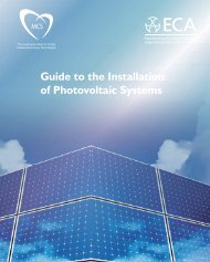
2.2.3 Tilt angle selection<br />
The tilt angle of the PV module is measured between the surface of the PV module<br />
and a horizontal ground surface (Figure 1). The PV module generates maximum<br />
output power when it faces the sun directly.<br />
Figure1: PV module title angle<br />
For standalone systems with batteries where the PV modules are attached to a<br />
permanent structure, the tilt angle of the PV modules should be selected to optimize<br />
the performance based on seasonal load and sunlight. In general, if the PV output is<br />
adequate when irradiance is low (e.g., winter), then the angle chosen should be<br />
adequate during the rest of the year. For grid-connected installations where the PV<br />
modules are attached to a permanent structure, PV modules should be tilted so that<br />
the energy production from the PV modules will be maximized on an annual basis.<br />
2.3 Mechanical <strong>Installation</strong> introduction<br />
Solar PV modules can be mounted using the following methods:<br />
*Note: <strong>All</strong> installation methods herein are only for reference, and <strong>Jinko</strong> solar will not<br />
provide related mounting components, the system installer or trained professional<br />
personnel must be responsible for the PV system’s design, installation, and<br />
mechanical load calculation and security of the system.<br />
7
Rev. C<br />
*Note: before installing, you should confirm below important things:<br />
1) Visual check before installation, to make sure there is no bug in the packing and<br />
junction box as well as the surface of module. , If have , remove and clean it .<br />
2) Check the series number to know is it right or not.<br />
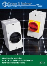
2.3.1 Screw fitting:<br />
The frame of each module has 8 mounting holes (Length* Width: 14mm*9mm) used<br />
to secure the modules to support structure. If the wind or snow loads is less than<br />
2400Pa , you can use the four symmetry holes close to the inner side on module<br />
frame. ,if the wind or snow load is bigger than 2400Pa, you must use all the eight<br />
mounting holes. The module frame must be attached to a mounting rail using M8<br />
corrosion-proof screws together with spring washers and flat washers in eight<br />
symmetrical locations on the PV module. The applied torque should be big enough to<br />
fix it steadily, for safety, you’d better follow the clamps manufacture’s<br />
recommendation. Please find detailed mounting information in the below illustration,<br />
8
Rev. C<br />
Figure 2 above: PV module installed with Screw fitting method*<br />
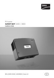
2.3.2 Fixation with clamps (at long side or short side)<br />
The module clamps should not come into contact with the front glass and must not<br />
deform the frame. Be sure to avoid shadowing effects from the module clamps. The<br />
module frame is not to be modified under any circumstances. When choosing this<br />
type of clamp-mounting method, please be sure to use at least four clamps on each<br />
module, two clamps should be attached on each long or short sides of the module.<br />
Depending on the local wind and snow loads, if the pressure load is more than<br />
2400Pa, additional clamps or support would be required to ensure the module can<br />
bear the load. The applied torque should be big enough to fix it steady ,Please find<br />
detailed mounting information in the below illustration, the mounting place distance is<br />
suggested bigger than J and less than K, as showed below.<br />
9
Rev. C<br />
Figure3 above: PV module installed at long side with Clamp fitting method<br />
Table 1 above: Mechanical dimensions when modules installed at long side with Clamp fitting<br />
method<br />
10
Rev. C<br />
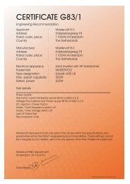
Figure 4 above: PV module installed at short side with Clamp fitting method<br />
Table 2 above: Mechanical dimensions when modules installed at short side with Clamp fitting<br />
method<br />
3. Wiring and connection<br />
11
Rev. C<br />
a) Before this procedure, please read the operation instructions of the PV system<br />
carefully. Make wiring by Multi-connecting cables between the PV modules in<br />
series or parallel connection, which is determined by user’s configuration<br />
requirement for system power, current and voltage.<br />
b) PV module connected in series should have similar current. Modules must not be<br />
connected together to create a voltage higher than the permitted system<br />
voltage(1000VDC), as reference the maximum number of modules in series (N)<br />
can be easily calculated by dividing the Maximum System Voltage of the modules<br />
by the respective Voc value of the module. Any more please always take into<br />
consideration the variation of the voltage under different temperatures, the Voc of<br />
the modules will be rise when the temperature drops.<br />
For example: with JKM190M-72 modules (Max. System voltage is 1000V) the<br />
maximum series modules configuration number should NEVER can exceed N= 22<br />
(1000V/45.2V = 22.1)<br />
c) PV module connect in parallel should have similar voltage. As reference the<br />
maximum number of modules in parallel (M) can be easily calculated by dividing<br />
the maximum rated current ( indicated in the electrical specification below) by Isc<br />
value of the module, and then plus 1. Any more please always take into<br />
consideration the variation of the current under different temperatures, the Isc of<br />
the modules will be rise when the temperature goes up.<br />
d) Open the connection box of the control system and connect the cabled from the PV<br />
arrays to the connection box in accordance with the installation indication of the PV<br />
control systems. The cross-sectional area and cable connector capacity must<br />
satisfy the maximum short-circuit of PV system (For a single component, we<br />
recommended the cross-sectional area of cables is 4mm 2 and the rated current of<br />
connectors is more than 10A), otherwise cables and connectors will become<br />
overheating for large current. Please pay attention: the temperature limit of cables<br />
is 85℃ and the temperature limit of connector 105℃)<br />
e) <strong>All</strong> module frames and mounting racks must be properly grounded in accordance<br />
with local and national electrical codes. Attach the equipment grounding conductor<br />
to the module frame using the hole and hardware provided. Note that a stainless<br />
steel star washer is used between the ground wire and the module frame (see<br />
picture below). This washer is used to avoid corrosion due to dissimilar metals.<br />
Tighten the screw securely.<br />
12
Rev. C<br />
Figure 5:The graph of Grounding<br />
f) Follow the requirements of applicable local and national electrical codes.<br />
g) These modules contain factory installed bypass diode .if these modules are<br />
incorrectly connected to each other, the bypass diodes, cable or junction box may be<br />
damaged.<br />
h) The cable of the junction box is 900 mm, as showed in below picture, please take<br />
the cable length into consideration before designing the wiring layout.<br />
4. Maintenance and care<br />
a) A built up of dust or dirt on the module(s) front face will result in a decreased<br />
energy output. Clean the panel(s) preferably once per annum if possible (depend on<br />
site conditions) using a soft cloth dry or damp, as necessary.<br />
b) Never use abrasive material under any circumstances.<br />
13
Rev. C<br />
c) Examine the PV module(s) for signs of deterioration. Check all wiring for possible<br />
rodent damage, weathering and that all connections are tight and corrosion free.<br />
Check electrical leakage to ground.<br />
d) Check fixing screws and mounting brackets are tight, adjust and tighten as<br />
necessary.<br />
e) When clean the modules, it is not allowed to stand on the module or the likes. Like<br />
below pictures show, this it prohibited.<br />
5. Electrical specification<br />
The module electrical rating are measured under Standard Test Conditions,<br />
which are 1000W/m 2 , irradiance with AM 1.5 spectrum and 25 deg (77°F) ambient<br />
temperature. The module might produce more or less voltage or current than rating<br />
value in uncertainty condition. Accordingly, the values of I SC and V OC marked on this<br />
module should be multiplied by a factor of 1.25 when determining component voltage<br />
ratings, conductor current ratings, fuse sizes, and size of controls connected to the<br />
PV output. Tables below are electrical characteristics of PV products at STC and the<br />
tolerance of Isc,Voc,Vmp and Imp is±10%.<br />
14
5.1.Electrical specifications of JKM xxxM-72(xxx=160-200) andJKMxxxM-72-I(xxx=160-200)<br />
Series Monocrystalline solar modules<br />
Rev. C<br />
Module Type<br />
JKM-<br />
160M<br />
JKM-<br />
165M<br />
JKM-<br />
170M<br />
JKM-<br />
175M<br />
JKM-<br />
180M<br />
JKM-<br />
185M<br />
JKM-<br />
190M<br />
JKM-<br />
195M<br />
JKM-<br />
200M<br />
Maximum Power at STC(Pmax) 160Wp 165Wp 170Wp 175Wp 180Wp 185Wp 190Wp 195Wp 200Wp<br />
Maximum Power Voltage (Vmp) 35.0V 35.3V 35.5V 35.8V 36.0V 36.4V 36.6V 36.8V 36.9V<br />
Maximum Power Current (Imp) 4.57A 4.67A 4.79A 4.90A 5.00A 5.09A 5.19A 5.30A 5.42 A<br />
Open-circuit Voltage (Voc) 43.9V 44.1V 44.3V 44.7V 44.8V 45.0V 45.2V 45.4V 45.6V<br />
Short-circuit Current (Isc) 4.93A 5.02A 5.12A 5.23A 5.29A 5.43A 5.56A 5.67A 5.80A<br />
Maximum system Voltage<br />
Dimensions<br />
Maximum rated current series(A)<br />
1580×808x35mm(62.20×31.81x1.38inch);<br />
1580×808x50mm (62.20×31.81x1.97 inch)<br />
1000VDC<br />
1580×808x45mm(62.20×31.81x1.77inch),<br />
10A<br />
15
5.2. Electrical specifications of JKMxxxM-96(xxx=220-270) and JKMxxxM-96-I(xxx=220-270)<br />
Series Monocrystalline solar modules<br />
Rev. C<br />
Module Type<br />
Maximum Power<br />
at STC(Pmax)<br />
Maximum Power<br />
Voltage (Vmp)<br />
Maximum Power<br />
Current (Imp)<br />
Open-circuit<br />
Voltage (Voc)<br />
Short-circuit<br />
Current (Isc)<br />
Maximum system<br />
Voltage<br />
JKM- JKM- JKM- JKM- JKM- JKM- JKM-<br />
220M 225M 230M 235M 240M 245M 250M<br />
JKM- JKM- JKM- JKM-<br />
255M 260M 265M 270M<br />
220Wp 225Wp 230Wp 235Wp 240Wp 245Wp 250Wp 255Wp 260Wp 265Wp 270Wp<br />
48.0V 48.3V 48.5V 48.8V 49.0V 49.1V 49.5V 50.0V 50.5V 51.0V 51.5 V<br />
4.58A 4.66A 4.74A 4.81A 4.89A 4.99A 5.05A 5.10A 5.15A 5.20A 5.24A<br />
58.8V 58.9V 59.1V 59.2V 59.5V 59.7V 59.9V 60.5V 61.1V 61.7V 62.3V<br />
5.01A 5.11A 5.19A 5.27A 5.35A 5.50A 5.61A 5.66A 5.72A 5.77A 5.82A<br />
1000VDC<br />
Dimensions 1575×1082x45mm (62.01×42.6×1.77 inch); 1575×1082x50mm (62.01×42.6×1.97 inch);<br />
Maximum rated<br />
current series(A)<br />
15A<br />
16
Rev. C<br />
5.3.Electrical specifications of JKMxxxM-60(xxx=200-250)Series Monocrystalline solar modules<br />
Module Type<br />
Maximum Power at<br />
STC(Pmax)<br />
Maximum Power<br />
Voltage (Vmp)<br />
Maximum Power<br />
Current (Imp)<br />
Open-circuit<br />
Voltage (Voc)<br />
Short-circuit<br />
Current (Isc)<br />
Maximum system<br />
Voltage<br />
Dimensions<br />
Maximum rated<br />
current series(A)<br />
JKM-2 JKM- JKM- JKM- JKM- JKM-<br />
00M 205M 210M 215M 220M 225M<br />
JKM- JKM- JKM- JKM- JKM-<br />
230M 235M 240M 245M 250M<br />
200Wp 205Wp 210Wp 215Wp 220Wp 225Wp 230Wp 235Wp 240Wp 245Wp 250Wp<br />
28.8V 29.0V 29.2V 29.3V 29.5V 29.7V 29.9V 30.0V 30.2V 30.4V 30.6V<br />
6.94A 7.07A 7.19A 7.34A 7.46A 7.57A 7.69A 7.83A 7.95A 8.06A 8.17A<br />
36.5V 36.6V 36.7V 36.8V 36.9V 37.0V 37.1V 37.2V 37.3V 37.4V 37.6V<br />
7.51A 7.62A 7.76A 7.85A 7.97A 8.08A 8.20A 8.31A 8.45A 8.58A 8.70A<br />
1000VDC<br />
1650×992x45(64.97×39.06 x1.77 inch) ; 1650x992x50(64.97×39.06 x1.97 inch)<br />
15A<br />
17
Rev. C<br />
5.4.Electrical specifications of JKMxxxP-60(xxx=200-250)and JKMxxxP-60-I(xxx=200-250)Series<br />
polycrystalline solar modules<br />
Module Type<br />
Maximum Power at<br />
STC(Pmax)<br />
Maximum Power Voltage<br />
(Vmp)<br />
Maximum Power Current<br />
(Imp)<br />
JKM-2 JKM- JKM- JKM- JKM- JKM- JKM- JKM- JKM-<br />
00P 205P 210 P 215 P 220 P 225 P 230 P 235 P 240 P<br />
JKM- JKM-<br />
245 P 250 P<br />
200Wp 205Wp 210Wp 215Wp 220Wp 225Wp 230Wp 235Wp 240Wp 245Wp 250Wp<br />
28.7V 28.8V 29.0V 29.1V 29.2V 29.4V 29.6V 29.8V 30.0V 30.2V 30.4V<br />
6.97A 7.12A 7.24A 7.39A 7.53A 7.65A 7.78A 7.89A 8.01A 8.12A 8.23A<br />
Open-circuit Voltage (Voc) 36.2V 36.3V 36.4V 36.5V 36.6V 36.7V 36.8V 36.9V 37.2V 37.4V 37.6V<br />
Short-circuit Current (Isc) 7.65A 7.76A 7.88A 7.99A 8.10A 8.25A 8.35A 8.47A 8.56A 8.69A 8.81A<br />
Maximum system Voltage<br />
Dimensions<br />
Maximum rated current<br />
series(A)<br />
1000VDC<br />
1650×992x45(64.97×39.06 x1.77 inch) ; 1650x992x50(64.97×39.06 x1.97 inch)<br />
15A<br />
18
Rev. C<br />
5.5.Electrical specifications of JKMxxxP-72(xxx=250-305)Series polycrystalline solar modules<br />
Module Type<br />
JKM- JKM-<br />
250P 255P<br />
Maximum Power at STC(Pmax) 250Wp<br />
255<br />
Wp<br />
Maximum Power Voltage (Vmp) 34.7V 34.9V<br />
Maximum Power Current (Imp) 7.20A 7.31A<br />
Open-circuit Voltage (Voc) 43.5V 43.7V<br />
Short-circuit Current (Isc) 8.11A 8.20A<br />
Maximum system Voltage<br />
Dimensions<br />
Maximum rated current series(A)<br />
JKM-<br />
260P<br />
260<br />
Wp<br />
35.0<br />
V<br />
7.43<br />
A<br />
43.9<br />
V<br />
8.30<br />
A<br />
JKM-<br />
265P<br />
JKM-<br />
270P<br />
JKM-<br />
275P<br />
JKM-<br />
280P<br />
JKM-<br />
285P<br />
JKM-<br />
290P<br />
265<br />
285 290<br />
270Wp 275 Wp 280Wp<br />
Wp<br />
Wp Wp<br />
JKM-<br />
295P<br />
JKM-<br />
300P<br />
JKM-<br />
305P<br />
295 300 305<br />
Wp Wp Wp<br />
35.1V 35.2V 35.4 V 35.5V 36.0 V 36.4 V 36.8 V 37.2 V 37.4 V<br />
7.55A 7.67A 7.77 A 7.89A 7.92 A 7.97 A 8.02 A 8.07 A 8.16 A<br />
44.1V 44.2V 44.4V 44.5V 44.7 V 44.9 V 45.2 V 45.4 V 45.6 V<br />
8.42 A 8.59A 8.70 A 8.81A 8.85 A 8.89 A 8.95 A 8.98 A 9.05 A<br />
1000VDC<br />
1956×992x50mm (77.01×39.06x1.97 inch)<br />
15A<br />
19
Rev. C<br />
5.6.Electrical specifications of JKMxxxM-72(xxx=250-305)Series polycrystalline solar modules<br />
Module Type<br />
Maximum Power<br />
at STC(Pmax)<br />
Maximum Power<br />
Voltage (Vmp)<br />
Maximum Power<br />
Current (Imp)<br />
Open-circuit<br />
Voltage (Voc)<br />
Short-circuit<br />
Current (Isc)<br />
Maximum<br />
system Voltage<br />
Dimensions<br />
Maximum rated<br />
current series(A)<br />
JKM- JKM- JKM- JKM- JKM- JKM- JKM-<br />
250M 255 M 260M 265M 270M 275M 280M<br />
250Wp 255 Wp 260Wp 265 Wp 270Wp<br />
275<br />
Wp<br />
280Wp<br />
JKM-<br />
285M<br />
JKM-<br />
290M<br />
JKM-<br />
295M<br />
JKM-<br />
300M<br />
JKM-<br />
305M<br />
285 290 295 300 305<br />
Wp Wp Wp Wp Wp<br />
35.6V 35.6V 35.8V 35.8V 35.9V 36.1V 36.3V 36.8V 37.2V 37.6V 38.0V 38.2V<br />
7.02A 7.16A 7.26A 7.40A 7.52A 7.61A 7.71A 7.74A 7.79A 7.85A 7.90A 7.99A<br />
44.3V 44.4V 44.6V 44.8V 45.0V 45.3V 45.4V 45.5V 45.7V 46.0V 46.4V 46.8V<br />
7.75A 7.90A 8.00A 8.13A 8.35A 8.37A 8.39A 8.41A 8.50A 8.59A 8.67A 8.72A<br />
1000VDC<br />
1956×992x50mm (77.01×39.06x1.97 inch)<br />
15A<br />
20
Rev. C<br />
6.Disclaimer of Liability<br />
Because the use of the manual and the conditions or methods of installation, operation, use and maintenance of<br />
photovoltaic (PV) product are beyond <strong>Jinko</strong>’s control, <strong>Jinko</strong> does not accept responsibility and expressly disclaims liability<br />
for loss ,damage, or expense arising out of or in any way connected with such installation, operation, use or maintenance.<br />
No responsibility is assumed by <strong>Jinko</strong> for any infringement of patents or other rights of third parties, which may result<br />
from use of the PV product.. NO license is granted by implication or otherwise under any patent or patent rights.<br />
The information in this manual is based on <strong>Jinko</strong>’s knowledge and experience and is believed to be reliable, but such<br />
information including product specification(without limitations)and suggestions do not constitute a warranty, expresses or<br />
implied .<strong>Jinko</strong> reserve the right to change the manual, the PV produce, the specifications, or product information sheets<br />
without prior notice.<br />
21
Rev. C<br />
6. Contact us<br />
<strong>Jinko</strong> Solar Co., Ltd. (Shanghai Office)<br />
12F, East Hope Plaza, No.1777 Century Avenue, Shanghai, China<br />
Postcode: 200122<br />
Tel:(86)-21-31268766<br />
Fax:(86)-21-68761115<br />
<strong>Jinko</strong> Solar Co., Ltd. (Jiangxi Manufacture Base)<br />
No.1 Jingko Road, Shangrao <strong>Eco</strong>nomic Development Zone, Jiangxi Province,<br />
China<br />
Postcode: 334100<br />
Tel:(86)-793-8588188<br />
Fax:(86)-793-8461152<br />
<strong>Jinko</strong> solar Import and Export co., LTD<br />
Xuri District, Shangrao <strong>Eco</strong>nomic Development Zone, Jiangxi Province, CHINA<br />
Postcode:334100<br />
Tel: +86-793-8469699<br />
Fax: +86-793-8461152<br />
Customer Service:modulecs@jinkosolar.com<br />
22