Product Catalogue 2012 - LK Systems AB
Product Catalogue 2012 - LK Systems AB
Product Catalogue 2012 - LK Systems AB

You also want an ePaper? Increase the reach of your titles
YUMPU automatically turns print PDFs into web optimized ePapers that Google loves.
Loading Units | <strong>LK</strong> 815 ThermoKit T<br />
<strong>LK</strong> 815 ThermoKit T<br />
Technical Data<br />
Voltage<br />
230 VAC 50 Hz<br />
Power consumption 30-390 W depending on<br />
pump speed<br />
Max. boiler capacity Dependent on circulating<br />
pump<br />
Return temperatures 45°C, 55°C, 61°C or 72°C<br />
Working temperature Min. +5°C/Max. +110°C<br />
Ambient temperature Min. +5°C/Max. +60°C<br />
Max. working pressure 1.0 MPa (10 bar)<br />
Max. flow<br />
Dependent on circulating<br />
pump<br />
Media<br />
Water - Glycol mixture<br />
max. 50%<br />
Circulating pumps Grundfos UPS 25-80,<br />
Grundfos UPS 25-60,<br />
Grundfos UPS 15-40 ES,<br />
Wilo Top-S 25/7 or<br />
Wilo Top-S 25/10<br />
Material, valve body Brass EN 12165 CW617N,<br />
Cast iron EN 1561 EN-GJL-200<br />
(with Wilo Top-S 25/10)<br />
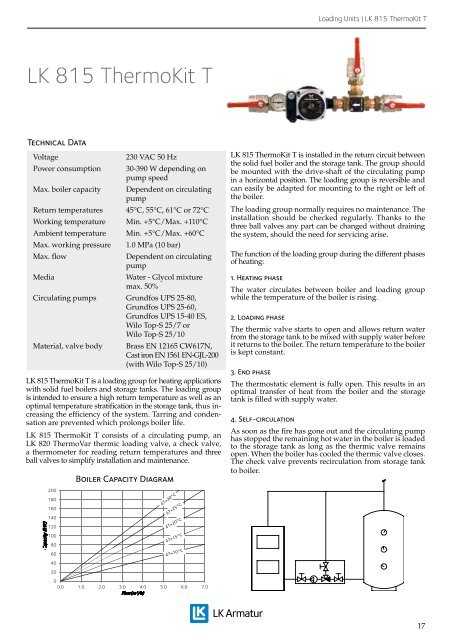
<strong>LK</strong> 815 ThermoKit T is a loading group for heating applications<br />
with solid fuel boilers and storage tanks. The loading group<br />
is intended to ensure a high return temperature as well as an<br />
optimal temperature stratification in the storage tank, thus increasing<br />
the efficiency of the system. Tarring and condensation<br />
are prevented which prolongs boiler life.<br />
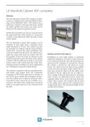
<strong>LK</strong> 815 ThermoKit T consists of a circulating pump, an<br />
<strong>LK</strong> 820 ThermoVar thermic loading valve, a check valve,<br />
a thermometer for reading return temperatures and three<br />
ball valves to simplify installation and maintenance.<br />
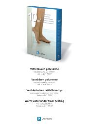
Capacity (kW)<br />
200<br />
180<br />
160<br />
140<br />
120<br />
100<br />
80<br />
60<br />
40<br />
20<br />
Boiler Capacity Diagram<br />
0<br />
0.0 1.0 2.0 3.0 4.0 5.0 6.0 7.0<br />
Flow(m³/h)<br />
<strong>LK</strong> 815 ThermoKit T is installed in the return circuit between<br />
the solid fuel boiler and the storage tank. The group should<br />
be mounted with the drive-shaft of the circulating pump<br />
in a horizontal position. The loading group is reversible and<br />
can easily be adapted for mounting to the right or left of<br />
the boiler.<br />
The loading group normally requires no maintenance. The<br />
installation should be checked regularly. Thanks to the<br />
three ball valves any part can be changed without draining<br />
the system, should the need for servicing arise.<br />
The function of the loading group during the different phases<br />
of heating:<br />
1. Heating phase<br />
The water circulates between boiler and loading group<br />
while the temperature of the boiler is rising.<br />
2. Loading phase<br />
The thermic valve starts to open and allows return water<br />
from the storage tank to be mixed with supply water before<br />
it returns to the boiler. The return temperature to the boiler<br />
is kept constant.<br />
3. End phase<br />
The thermostatic element is fully open. This results in an<br />
optimal transfer of heat from the boiler and the storage<br />
tank is filled with supply water.<br />
4. Self-circulation<br />
As soon as the fire has gone out and the circulating pump<br />
has stopped the remaining hot water in the boiler is loaded<br />
to the storage tank as long as the thermic valve remains<br />
open. When the boiler has cooled the thermic valve closes.<br />
The check valve prevents recirculation from storage tank<br />
to boiler.<br />
17