Calculation of stress-strain dependence from tensile tests at ... - RMZ
Calculation of stress-strain dependence from tensile tests at ... - RMZ
Calculation of stress-strain dependence from tensile tests at ... - RMZ

Create successful ePaper yourself
Turn your PDF publications into a flip-book with our unique Google optimized e-Paper software.
<strong>RMZ</strong> – M<strong>at</strong>erials and Geoenvironment, Vol. 59, No. 4, pp. 331–346, 2012<br />
331<br />
<strong>Calcul<strong>at</strong>ion</strong> <strong>of</strong> <strong>stress</strong>-<strong>strain</strong> <strong>dependence</strong> <strong>from</strong> <strong>tensile</strong> <strong>tests</strong> <strong>at</strong><br />
high temper<strong>at</strong>ures using final shapes <strong>of</strong> specimen’s contours<br />
Določitev odvisnosti napetost – deformacija z n<strong>at</strong>eznimi preizkusi<br />
v vročem in na osnovi končnih oblik n<strong>at</strong>eznih palic<br />
Goran Kugler 1 , Milan Terčelj 1 , Iztok Peruš 1,2 &Rado Turk 1,*<br />
1<br />
University <strong>of</strong> Ljubljana, Faculty <strong>of</strong> N<strong>at</strong>ural Sciences and Engineering, Aškerčeva 12,<br />
SI-1000 Ljubljana, Slovenia<br />
2<br />
University <strong>of</strong> Ljubljana, Faculty <strong>of</strong> Civil and Geodetic Engineering, Jamova 2,<br />
SI-1000 Ljubljana, Slovenia<br />
*Corresponding author. E-mail: Rado.Turk@ntf.uni-lj.si<br />
Received: October 26, 2012 Accepted: November 26, 2012<br />
Abstract: The new m<strong>at</strong>hem<strong>at</strong>ical model is proposed th<strong>at</strong> enable calcul<strong>at</strong>ion<br />
<strong>of</strong> true <strong>stress</strong> – true <strong>strain</strong> <strong>dependence</strong> <strong>from</strong> the results <strong>of</strong> <strong>tensile</strong> <strong>tests</strong><br />
also after appearing <strong>of</strong> necking. Based on this model the computer<br />
program was developed which <strong>from</strong> the measured final shapes <strong>of</strong> the<br />
<strong>tensile</strong> specimens and <strong>from</strong> <strong>tensile</strong> testing d<strong>at</strong>a autom<strong>at</strong>ically determine<br />
the time evolution <strong>of</strong> the specimen’s contour, <strong>strain</strong> r<strong>at</strong>e and<br />
<strong>stress</strong>-<strong>strain</strong> rel<strong>at</strong>ion. In order to <strong>tests</strong> and valid<strong>at</strong>e the model <strong>tensile</strong><br />
<strong>tests</strong> <strong>at</strong> different prescribed <strong>strain</strong> r<strong>at</strong>es and temper<strong>at</strong>ures on specimens<br />
made <strong>of</strong> nickel alloy Alloy201 were carried out on thermo-mechanical<br />
simul<strong>at</strong>or Gleeble 1500D. It was found th<strong>at</strong> after occurrence<br />
<strong>of</strong> neck the true <strong>strain</strong> r<strong>at</strong>e is constantly increasing throughout the<br />
test. Further it was found th<strong>at</strong> plastic part <strong>of</strong> the rod can be well approxim<strong>at</strong>ed<br />
with constant and with c<strong>at</strong>enary but Bridgman correction<br />
can be determined only if c<strong>at</strong>enary is used. Comparison <strong>of</strong> predicted<br />
evolution <strong>of</strong> minimal radius <strong>at</strong> the neck with measured one showed<br />
excellent agreement.<br />
Izvleček: V delu je opisan nov m<strong>at</strong>em<strong>at</strong>ični model, s k<strong>at</strong>erim je mogoče na<br />
podlagi rezult<strong>at</strong>ov n<strong>at</strong>eznih preizkusov tudi po pojavu skrčka določiti<br />
odvisnost prava napetost – prava deformacija. Na osnovi modela je bil<br />
narejen računalniški program, ki na podlagi izmerjenih končnih oblik<br />
Original scientific paper
332 Kugler, G., Terčelj, M., Peruš, I., Turk, R.<br />
n<strong>at</strong>eznih palic in pod<strong>at</strong>kov n<strong>at</strong>eznih preizkusov avtom<strong>at</strong>ično določi<br />
časovni razvoj kontur n<strong>at</strong>eznih vzorcev in izračuna hitrost deformacije<br />
ter zvezo med napetostjo in deformacijo. Model je bil preizkušen<br />
in preverjen z n<strong>at</strong>eznimi preizkusi, ki so bili za nikljevo zlitino<br />
Alloy201 pri različnih predpisanih konstantnih hitrostih deformacije<br />
in konstantnih temper<strong>at</strong>urah narejeni na simul<strong>at</strong>orju termomehanskih<br />
metalurških stanj Gleeble 1500D. Ugotovljeno je bilo, da prava hitrost<br />
deformacije po pojavu skračka začne narašč<strong>at</strong>i in narašča vse<br />
do konca preizkusa. Nadalje je pokazano, da lahko del palice, ki je<br />
v plastičnem stanju, zelo dobro aproksimiramo tako s konstanto kot<br />
tudi z verižnico, vendar pa je Bridgmanov popravek mogoče določiti<br />
le pri aproksimaciji z verižnico. Rezult<strong>at</strong>i razvoja minimalnega radija<br />
v skrčku, dobljeni s predlaganim modelom, se odlično ujemajo z meritvami.<br />
Key words: <strong>tensile</strong> test, necking, hot deform<strong>at</strong>ion, <strong>strain</strong>-<strong>stress</strong> curves.<br />
Ključne besede: n<strong>at</strong>ezni preizkus, skrček, deformacija v vročem, krivulje<br />
deformacija – napetost<br />
Introduction<br />
From the test for determin<strong>at</strong>ion <strong>of</strong> hot<br />
workability <strong>of</strong> metallic m<strong>at</strong>erials it is<br />
required to enable measurement <strong>of</strong><br />
force applied on sample as a function<br />
<strong>of</strong> its deform<strong>at</strong>ion <strong>at</strong> constant <strong>strain</strong><br />
r<strong>at</strong>e and constant temper<strong>at</strong>ure. There<br />
are three most important <strong>tests</strong>, i.e.<br />
compression test, torsion test and <strong>tensile</strong><br />
test. Each <strong>of</strong> the <strong>tests</strong> has its own<br />
problems, i.e. weaknesses, which impeded<br />
gaining <strong>of</strong> reliable d<strong>at</strong>a about<br />
<strong>stress</strong>, <strong>strain</strong>, <strong>strain</strong> r<strong>at</strong>e, deformability,<br />
etc. Compression test has seemingly<br />
the most advantages: geometry <strong>of</strong> cylindrical<br />
specimens is easy for machining<br />
and higher <strong>strain</strong>s as well as <strong>strain</strong><br />
r<strong>at</strong>es can be achieved in comparison<br />
to <strong>tensile</strong> test, but due to the presence<br />
<strong>of</strong> friction between compression anvil<br />
and specimen buckling can occur especially<br />
<strong>at</strong> slightly higher <strong>strain</strong>s. Thus<br />
uniaxial <strong>stress</strong> st<strong>at</strong>e in deformed specimen<br />
is present only up to the beginning<br />
<strong>of</strong> its buckling when also reliable<br />
value rel<strong>at</strong>ed to hot deform<strong>at</strong>ion can be<br />
obtained. In case <strong>of</strong> exceeding <strong>of</strong> mentioned<br />
compression <strong>strain</strong> additional<br />
s<strong>of</strong>tware is needed for gaining <strong>of</strong> more<br />
reliable d<strong>at</strong>a. Hot torsion testing takes<br />
place without presence <strong>of</strong> friction;<br />
moreover this test is very appropri<strong>at</strong>e<br />
for assessment <strong>of</strong> hot workability since<br />
higher <strong>strain</strong> can be achieved by this<br />
type <strong>of</strong> testing th<strong>at</strong> increase the reliability.<br />
But its weakness is in control<br />
(maintenance) <strong>of</strong> constant temper<strong>at</strong>ure<br />
during test, inhomogeneity <strong>of</strong> deform<strong>at</strong>ion<br />
so along working length <strong>of</strong><br />
<strong>RMZ</strong>-M&G 2012, 59
<strong>Calcul<strong>at</strong>ion</strong> <strong>of</strong> <strong>stress</strong>-<strong>strain</strong> <strong>dependence</strong> <strong>from</strong> <strong>tensile</strong> <strong>tests</strong> <strong>at</strong> high temper<strong>at</strong>ures using ...<br />
333<br />
specimen as well as in radial direction.<br />
Especially due to the l<strong>at</strong>est weakness<br />
<strong>strain</strong> and <strong>strain</strong> r<strong>at</strong>e can be expressed<br />
as equivalent <strong>strain</strong> and <strong>strain</strong> r<strong>at</strong>e. At<br />
hot <strong>tensile</strong> testing also non-homogeneity<br />
<strong>of</strong> deform<strong>at</strong>ion occurs on specimen<br />
working length th<strong>at</strong> is expressed<br />
by its necking. It is well known, th<strong>at</strong><br />
for <strong>tensile</strong> test homogenous deform<strong>at</strong>ion<br />
takes place only untilappearance<br />
<strong>of</strong> necking which occurs <strong>at</strong> <strong>strain</strong>s <strong>of</strong><br />
approxim<strong>at</strong>ely between 0.2 and 0.3,<br />
depending on precision <strong>of</strong> manufacturing<br />
<strong>of</strong> the <strong>tensile</strong> samples, onm<strong>at</strong>erials<br />
inhomogeneity, on temper<strong>at</strong>ure gradient<br />
along the <strong>tensile</strong> axis, etc.<br />
When the neck appears, the <strong>stress</strong> st<strong>at</strong>e<br />
change <strong>from</strong> uniaxial to multi-axialmust<br />
be taken into account. The correction<br />
due to multi-axiality is usuallydone<br />
by Bridgman correction, which<br />
presumes th<strong>at</strong> portion <strong>of</strong> the contour<br />
inclose neighborhood <strong>of</strong> the minimal<br />
cross-section <strong>of</strong> the neck may be characterized<br />
by a single parameter, the<br />
radius <strong>of</strong> curv<strong>at</strong>ure <strong>of</strong> the circle oscul<strong>at</strong>ing<br />
the pr<strong>of</strong>ile <strong>at</strong> the neck. [1] But obtaining<br />
reliable d<strong>at</strong>a on <strong>stress</strong> – <strong>strain</strong><br />
rel<strong>at</strong>ion <strong>from</strong> <strong>tensile</strong> <strong>tests</strong> after appearance<br />
<strong>of</strong> necking is very difficult<br />
task especially if testing is conducted<br />
<strong>at</strong> elev<strong>at</strong>ed temper<strong>at</strong>ures, which is exactly<br />
the case if one wants to study hot<br />
workability <strong>of</strong> metallic m<strong>at</strong>erials.<br />
The aims <strong>of</strong> this study are therefore to<br />
evalu<strong>at</strong>e the possibility <strong>of</strong> applicability<br />
<strong>of</strong> <strong>tensile</strong> test for determin<strong>at</strong>ion <strong>of</strong> hot<br />
working properties <strong>of</strong> metallicm<strong>at</strong>erials<br />
also after the appearance <strong>of</strong> necking<br />
and to introduce appropri<strong>at</strong>emodel for<br />
calcul<strong>at</strong>ion <strong>of</strong> <strong>stress</strong>-<strong>strain</strong> <strong>dependence</strong><br />
<strong>from</strong> the final shapes <strong>of</strong>contours <strong>of</strong> <strong>tensile</strong><br />
loaded specimens.<br />
Experimental procedure<br />
A commercially produced Ni alloy<br />
Alloy201 was supplied by Thyssen-<br />
Krupp Gmbh as hot drowned rods with<br />
chemical composition given in Table<br />
1 and equiaxed grain structure with an<br />
average grain size <strong>of</strong> about 16 μm.<br />
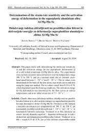
Cylindrical specimens with dimensions<br />
<strong>of</strong> 25 mm <strong>of</strong> effective length and<br />
<strong>of</strong> 8 mm in diameter where machined<br />
<strong>from</strong> supplied rods for hot <strong>tensile</strong> <strong>tests</strong><br />
(see Figure 1 for specimen’s geometry<br />
and dimensions).<br />
Table 1. Chemical composition <strong>of</strong> the commercially pure Ni (Alloy201) tested in mass<br />
fractions w/%<br />
Mo Cr Si S Mg Co Cu P<br />
0.001 0.004 0.05 0.001 0.03 0.07 0.006 0.006<br />
Mn Ti Fe Sn C V Al Ni<br />
0.13 0.04 0.13 0.01 0.02 0.002 0.023 rest<br />
<strong>RMZ</strong>-M&G 2012, 59
334 Kugler, G., Terčelj, M., Peruš, I., Turk, R.<br />
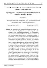
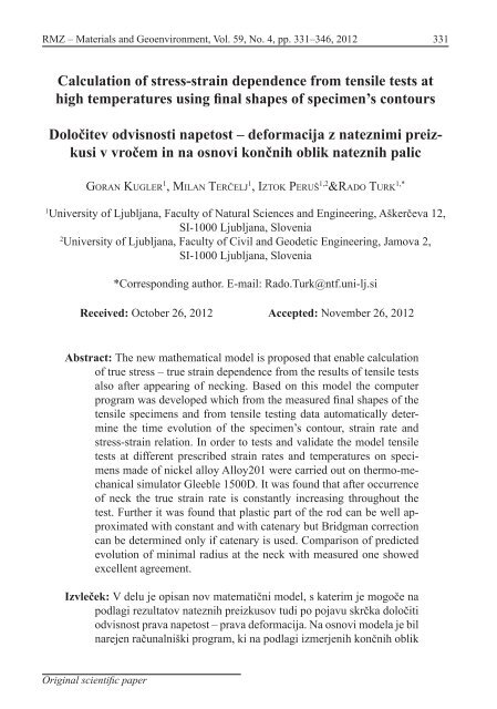
Figure1. Dimension <strong>of</strong> specimen’s for <strong>tensile</strong> testing.<br />
(a)<br />
(b)<br />
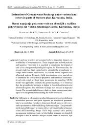
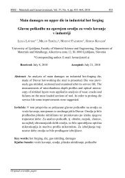
Figure2. Schem<strong>at</strong>ic represent<strong>at</strong>ion <strong>of</strong> temper<strong>at</strong>ure control (left), and<br />
shaping <strong>of</strong> contour (right) during hot <strong>tensile</strong> testing <strong>of</strong> Alloy201.<br />
The hot <strong>tensile</strong> <strong>tests</strong> were carried out<br />
on Gleeble 1500D thermomechanical<br />
testing machine. The samples were deformed<br />
between 8 mm and 11 mm <strong>at</strong><br />
temper<strong>at</strong>ures <strong>from</strong> 800 °C to 1000 °C<br />
under prescribed constant <strong>strain</strong> r<strong>at</strong>es<br />
between 10 –3 s –1 and 10 –1 s –1 assuming<br />
th<strong>at</strong> deform<strong>at</strong>ion was homogeneous on<br />
entire working length. The temper<strong>at</strong>ure<br />
as a function <strong>of</strong> time during <strong>tensile</strong> <strong>tests</strong><br />
is shown on Figure 2a, and specimen<br />
during testing is shown on Figure 2b.<br />
Essentially the deformed shape-<strong>of</strong>the-rod<br />
after <strong>tensile</strong> testing represents<br />
the history <strong>of</strong> traveling <strong>of</strong> the crosssection<br />
th<strong>at</strong> separ<strong>at</strong>es the elastic and<br />
plastic st<strong>at</strong>e <strong>of</strong> m<strong>at</strong>erial. [3, 4] The portion<br />
<strong>of</strong> m<strong>at</strong>erial th<strong>at</strong> in a given moment<br />
left the plastic st<strong>at</strong>e preserves its shape<br />
until the end <strong>of</strong> the experiment.Based<br />
on this fact, in wh<strong>at</strong> follows, the new<br />
model for description <strong>of</strong> evolution <strong>of</strong><br />
specimen’s contours during <strong>tensile</strong><br />
testing will be introduced.<br />
Description <strong>of</strong> the m<strong>at</strong>hem<strong>at</strong>ical approach<br />
Model for description <strong>of</strong> contour <strong>of</strong><br />
<strong>tensile</strong> specimen<br />
A cylindrical rod <strong>of</strong> radius, r, maintains<br />
its rot<strong>at</strong>ional symmetry around<br />
the longitudinal axis, z, during a <strong>tensile</strong><br />
test, and thus its shape <strong>at</strong> given<br />
time, t, is determined by the rot<strong>at</strong>ional<br />
curve r = r(z, t), which forms its sur-<br />
<strong>RMZ</strong>-M&G 2012, 59
<strong>Calcul<strong>at</strong>ion</strong> <strong>of</strong> <strong>stress</strong>-<strong>strain</strong> <strong>dependence</strong> <strong>from</strong> <strong>tensile</strong> <strong>tests</strong> <strong>at</strong> high temper<strong>at</strong>ures using ...<br />
335<br />
= (, <br />
face after rot<strong>at</strong>ion around longitudinal elastic parts <strong>of</strong> the rod. These )<br />
two<br />
axis, z, <strong>of</strong> the rod. Before the test this points were moving along the () curve<br />
curve is a cylinder r(z, 0) = r 0<br />
, where r = r(z, t k<br />
), during <strong>tensile</strong> test. Thus,<br />
r 0<br />
is the initial radius <strong>of</strong> the rod. After the rod may be () <strong>at</strong> = any = time divided<br />
(, )<br />
= (, )<br />
the test is finished this curve must be into three parts<br />
<br />
carefully measured to obtain results () in<br />
()<br />
()<br />
()<br />
the form<br />
() = = (, )<br />
= ( (, ) + (, ) + <br />
= (, )<br />
<br />
(1)<br />
()<br />
()<br />
()<br />
where t k<br />
is the dur<strong>at</strong>ion <strong>of</strong> the experi-<br />
= = ( Initial (, volume (, ) ) + <strong>of</strong> the rod (, ) <strong>of</strong> + (, ))<br />
(3)<br />
( (), ) = ( (), )<br />
() = ment.<br />
length, l o<br />
, is V 0<br />
= πr 2 l 0<br />
. The <br />
volume is<br />
()<br />
()<br />
()<br />
0<br />
conserved during plastic deform<strong>at</strong>ion,<br />
= (, )<br />
and<br />
()<br />
thus volume ( for (), ()<br />
an arbitrary ) = ( time (), The ) first and last sections belong to<br />
, ) + can be expressed (, ) as + <br />
= (, )<br />
()<br />
(, ))<br />
the elastic part and the middle section<br />
()<br />
to the plastic part <strong>of</strong> the rod. The final<br />
()<br />
() ()<br />
( (), ) = ( (), ) = ( (), )<br />
= (, )shape <strong>of</strong> the rod represents the line<br />
( (2) <strong>of</strong> movements <strong>of</strong> the points which<br />
(),<br />
()<br />
) =<br />
(<br />
=<br />
(),<br />
<br />
) (, ) (, )<br />
separ<strong>at</strong>e plastic and elastic = (, st<strong>at</strong>e ()<br />
= (, )<br />
)<br />
<strong>of</strong> <br />
<br />
<br />
the m<strong>at</strong>erial. The portion () <br />
<strong>of</strong> the curve ()<br />
() ( (), ) = ( (), ) = ( (), ) ()<br />
()<br />
where l(t) is the length <strong>of</strong> the rod <strong>at</strong> r = r(z, t k<br />
), th<strong>at</strong> lies left <strong>of</strong> the minimal<br />
) cross-section is a monotonically = (, )<br />
= <br />
time t. By ()<br />
()<br />
(, )<br />
(, )<br />
( (, ) + comparison (, )between + final<br />
(, )<br />
(, )<br />
<br />
shape<br />
()<br />
<strong>of</strong> the rod and<br />
<br />
its shape<br />
= (, () = <br />
) = (, )<br />
<strong>at</strong> arbitrary<br />
moment after occurrence <strong>of</strong> neck, the right is a () monotonically increasing<br />
<br />
= (, <br />
decreasing function<br />
)<br />
and () the portion<br />
<br />
<br />
on ()<br />
<br />
() () () ()<br />
(), ) =<br />
but<br />
( before<br />
(), )<br />
the<br />
= (<br />
end (),<br />
<strong>of</strong><br />
<br />
the )<br />
( test, we ascertain<br />
th<strong>at</strong> both shapes differ only in <strong>of</strong> l l<br />
function. Thus for the prescribed value<br />
(), ) (, = ()<br />
(), )<br />
(t) the value <strong>of</strong> l d<br />
(t) can be calcul<strong>at</strong>ed<br />
()<br />
(, )<br />
the middle, = (, but = (, ()<br />
()<br />
()<br />
)<br />
() = (, ) = ( <br />
<br />
() the end () <br />
()<br />
<br />
= <br />
(, ) = <br />
+ <br />
(, (, )<br />
) + (, ))<br />
<br />
parts are the <strong>from</strong> the<br />
<br />
<br />
() condition () ()<br />
same. () Namely, the rod () <strong>at</strong> the intermedi<strong>at</strong>e<br />
= <br />
<br />
time is shorter (, )<br />
() ()<br />
()<br />
()<br />
and it has a smaller<br />
(4)<br />
(, )<br />
neck. = Thus, (, <br />
we () )<br />
can conclude th<strong>at</strong> the = <br />
<br />
( <br />
(, (, ) <br />
() = (), ) = ( (), )<br />
= ( (, (, ) ) + )<br />
parts () <strong>of</strong> the rod, which () have the same From those two <br />
+<br />
1 +<br />
<br />
<br />
)<br />
<br />
)<br />
<br />
() <br />
() () values the () volume <br />
( (),<br />
shape<br />
)<br />
as<br />
=<br />
it<br />
(<br />
is <br />
<strong>at</strong><br />
(),<br />
the<br />
)<br />
end<br />
= (<br />
<strong>of</strong> the (),<br />
test,<br />
)<br />
were which is <strong>at</strong> given time in plastic st<strong>at</strong>e<br />
<strong>at</strong> th<strong>at</strong><br />
()<br />
moment in an elastic st<strong>at</strong>e and can be calcul<strong>at</strong>ed<br />
(, )<br />
() = the part, <br />
which (, = ) is (, different, )<br />
(<br />
was in plastic<br />
<br />
) = <br />
= <br />
= (, )<br />
( <br />
(, ) (, ) (), ) = ( (), )<br />
()<br />
st<strong>at</strong>e. Consequently, 1 + <br />
() <br />
<br />
<br />
on deformed<br />
()<br />
()<br />
()<br />
( (<br />
(), ) = ( <br />
(), ) ) = ( (), ) <br />
rod there are always two points th<strong>at</strong> <strong>at</strong><br />
(5)<br />
(,<br />
given )<br />
moment = separ<strong>at</strong>e (, = (, )<br />
)<br />
the plastic and<br />
= ( (, ) + (, ))<br />
<br />
(, ) (, ) ( <br />
<br />
1 + () ) = (, ) <br />
<br />
()<br />
= (, ()<br />
)<br />
<br />
<br />
<br />
<strong>RMZ</strong>-M&G 2012, 59<br />
() ()<br />
( (), ) = ( (), ) = ( (), )<br />
<br />
() ( )<br />
= ( (, ) + (, )<br />
) (, () = )<br />
(, ))<br />
()<br />
<br />
()<br />
()
= ( (, ) + = (, ()<br />
(, ) + )<br />
(, ))<br />
() ()<br />
<br />
336() = ()<br />
()<br />
= ()<br />
()<br />
()<br />
(, )<br />
Kugler, G., Terčelj, M., Peruš, I., Turk, R.<br />
<br />
()<br />
( (), ) = ( (), )<br />
= ( (, ) + (, ) + (, ))<br />
<br />
() ( <br />
= (), (, <br />
= ) = ) ( (), (, ) )<br />
()<br />
()<br />
()<br />
()<br />
The idea for<br />
()<br />
reconstruction <strong>of</strong><br />
()<br />
the step the system <strong>of</strong> linear or non-linear<br />
( intermedi<strong>at</strong>e ()<br />
<br />
(, ) + shapes <strong>of</strong> the rod (<br />
(, ) + is<br />
<br />
equ<strong>at</strong>ions must = <br />
be solved depending (), <br />
(, ) = (<br />
))<br />
(), ) (, )<br />
on<br />
() () now = to find ()<br />
the approxim<strong>at</strong>e ()<br />
= (, ) func-<br />
(, f(z,t) ) + ≈ r(z,t), ()<br />
for (, which ) + <br />
selected function. The simplest<br />
()<br />
choice<br />
<br />
()<br />
()<br />
( tion for ()<br />
<br />
(, ) the ) selection <strong>of</strong> function is certainly<br />
the constant, which upon rot<strong>at</strong>ion<br />
( (), () ) = ( (), ) ()<br />
( (), ) = ( (), ) = ( (), )<br />
= (, )<br />
()<br />
<br />
( (), ) = ()<br />
()<br />
( (), ) = ( (), ) (6) around its axes forms cylinder. Unfortun<strong>at</strong>ely<br />
the conditions (7) and (8) can-<br />
(, )( + ()<br />
(), <br />
) (, =<br />
where (, l)<br />
c<br />
(t) is the length <strong>from</strong> the beginning<br />
<strong>of</strong> = ()<br />
not be fulfilled for approxim<strong>at</strong>ion with<br />
= (, ( ) (), + <br />
)<br />
()<br />
(, )<br />
(, ))<br />
= (, )<br />
<br />
)<br />
<br />
<br />
<br />
<br />
the<br />
<br />
rod<br />
()<br />
to the ( <br />
(, )<br />
()<br />
() ()<br />
(), ) = ( (), ) = ( (), )<br />
() end <strong>of</strong><br />
<br />
the<br />
()<br />
plastic cylinder. Besides th<strong>at</strong>, the radius <strong>of</strong><br />
part. Since the<br />
()<br />
( (), contour <strong>of</strong> deformed rod curv<strong>at</strong>ure <strong>of</strong> the contour <strong>at</strong> the minimal<br />
<br />
is (, smooth, = ) = ( <br />
) it immedi<strong>at</strong>ely follows for cross-section is needed for calcul<strong>at</strong>ion<br />
the left end side= (, (), (, ) ) (, ) (, )<br />
= (, )<br />
= (, )<br />
)<br />
<br />
<br />
<br />
<br />
<br />
( (), ) = ( (), ) = ( (), )<br />
() <br />
()<br />
()<br />
() ()<br />
<strong>of</strong> the Bridgman <strong>stress</strong> correction, [1] ()<br />
but<br />
() ()<br />
for the approxim<strong>at</strong>ion by cylinder this<br />
( (, = (, <br />
(), = ) = ( ()<br />
(), (, )<br />
= ) (<br />
(,<br />
(), <br />
)<br />
)<br />
() (7) radius = (, )<br />
is infinite. On the other hand, for<br />
<br />
()<br />
() <br />
() = <br />
an arbitrary function this radius, R,can<br />
() = ()<br />
(, )<br />
= (, ) () ()<br />
(, )<br />
)<br />
<br />
be calcul<strong>at</strong>ed <strong>from</strong><br />
()<br />
( (, and for ) the right ()<br />
= end (, one <br />
(), ) = (<br />
(), ) = (<br />
() (),<br />
) <br />
)<br />
()<br />
()<br />
<br />
() <br />
(,<br />
<br />
(8)<br />
= <br />
()<br />
(, )<br />
<br />
(, <br />
)<br />
) = (, = (, )<br />
(, )<br />
) <br />
= <br />
<br />
<br />
(, (, ) <br />
() = )<br />
<br />
<br />
() 1 + () <br />
1 + <br />
()<br />
<br />
() () <br />
<br />
()<br />
(10) ( <br />
(, ) () = (, ) ( )<br />
<br />
Due to the constancy ()<br />
= (, )<br />
= <strong>of</strong> the volume<br />
() <br />
<br />
<br />
(, ) (, ) <br />
( ) = <br />
during () plastic = ( <br />
deform<strong>at</strong>ion, ) = () <br />
(, ) it also 1 + <br />
<br />
() follows<br />
<br />
)<br />
(<br />
<br />
<br />
<br />
where r min<br />
is the minimal radius <strong>at</strong> time t.<br />
= <br />
<br />
<br />
(, ) () () (, ) <br />
(9)<br />
= 1 + ( = ( (, ) + ) = <br />
(, ))<br />
( (, ) + <br />
<br />
(, ))<br />
( <strong>Calcul<strong>at</strong>ion</strong> )<br />
= <br />
() = (, ) <br />
(, ) (, ) <br />
<br />
<br />
<strong>of</strong> <strong>stress</strong>-<strong>strain</strong> <strong>dependence</strong><br />
<br />
<br />
()<br />
<br />
1 + <br />
<br />
<br />
<br />
<br />
The value <strong>of</strong> (l c<br />
(t) ) = which <br />
<br />
must be gre<strong>at</strong>er ( After ) hot <strong>tensile</strong> testing the measurements<br />
<strong>of</strong> deformed rods were carried<br />
<br />
= ( (, ) + (, ))<br />
<br />
(,<br />
than<br />
)<br />
the length<br />
(,<br />
<strong>of</strong> cylinder<br />
) <br />
() = (, ))<br />
<strong>of</strong> the same<br />
() <br />
= <br />
volume and <br />
<br />
<br />
1 + <br />
( (, ))<br />
radius )<br />
<br />
<br />
= <br />
r = r(l l<br />
, t k<br />
) on one out by the measurement microscope,<br />
<br />
hand = ( and must (, ) be smaller + <br />
than (,<br />
(<br />
) l d<br />
(t) ) on<br />
)<br />
which autom<strong>at</strong>ically save the ( measured<br />
)<br />
<br />
<br />
the other hand, is determined<br />
(<br />
( iter<strong>at</strong>ively.<br />
For the function model th<strong>at</strong> fulfils d<strong>at</strong>a only those N points for which r i<br />
<br />
() ) = = <br />
<br />
table <strong>of</strong> d<strong>at</strong>a (, ))<br />
r i<br />
= r i<br />
(z i<br />
). From measured<br />
<br />
)<br />
≤<br />
(( ))[1 = the + (( conditions 2((<br />
)(, = )) ) <br />
(6), (7), ((<br />
+ (8) ))<br />
<br />
(, ))<br />
(( ))[1 + 2(( )) (( ))] ln(1 + <br />
<br />
<br />
] ln(1<br />
and<br />
+<br />
(9),<br />
the<br />
(( r<br />
)) <br />
o<br />
, where<br />
2((<br />
r )))<br />
<br />
o<br />
is radius <strong>of</strong> non-deformed<br />
<br />
<br />
<br />
polynomial () = or any other suitable function<br />
could<br />
rod, are taken into account. Additionally<br />
be<br />
ln( ( ) = ln( (( )))<br />
( (, ))<br />
used. <br />
= ( ) =<br />
(, ) + In (( any (, case ))[1 ) ) due + ) 2(( to the<br />
)) two (( points )) ] ln(1<br />
which<br />
+<br />
are the nearest<br />
mentioned () = conditions in <br />
(, every )iter<strong>at</strong>ion<br />
) to the interval <strong>of</strong> N<br />
<br />
points<br />
= <br />
(( )) 2(( )))<br />
are also con-<br />
= <br />
(<br />
) <br />
<br />
= ln( (( )))<br />
<br />
(( ))[1 + 2(( )) (( ))] ln(1 + (( )) 2(( )))<br />
() = (<br />
<br />
1 (, )<br />
) )<br />
= <br />
= 1 = <br />
<br />
<br />
<br />
<br />
<strong>RMZ</strong>-M&G 2012, 59<br />
<br />
<br />
+ <br />
=
() = (, )<br />
()<br />
()<br />
()<br />
<strong>Calcul<strong>at</strong>ion</strong> () = <strong>of</strong> <strong>stress</strong>-<strong>strain</strong> <strong>dependence</strong> <strong>from</strong> <strong>tensile</strong> <strong>tests</strong> <strong>at</strong> high temper<strong>at</strong>ures using ... 337<br />
= = (, )<br />
(, )<br />
()<br />
= <br />
<br />
<br />
<br />
(, ) (, ) <br />
sidered. For reconstruction <strong>of</strong> contour ing 1 + <br />
()<br />
()<br />
()<br />
is true V p<br />
= V o<br />
–V e<br />
. For the part <strong>of</strong><br />
(), ) = the (continuous (), ) = ( function (), is ) needed and the rod which is in the plastic st<strong>at</strong>e ( two )<br />
= ( (, ) + (, ) + (, ))<br />
thus, cubic splines were applied for additional conditions are valid, namely<br />
(, ) <br />
interpol<strong>at</strong>ion = (, ()<br />
<br />
which )<br />
()<br />
yields continuous<br />
() function r r(z). ()<br />
it cannot (<br />
<br />
be ) longer = than s 1<br />
V p<br />
⁄πr 2 (l l<br />
)<br />
<br />
(<br />
The next step is and cannot be shorter than s 2<br />
= l d<br />
–l l<br />
,<br />
(), ) = ( (), )<br />
<br />
<br />
now the calcul<strong>at</strong>ion <strong>of</strong> the volume <strong>of</strong> respectively.<br />
(, ) the rod which undergoes plastic deform<strong>at</strong>ion.<br />
() Here the Simpson () integr<strong>at</strong>ion Let construct the function <br />
= (, )<br />
= ( (, ) + ()<br />
(, ))<br />
<br />
<br />
<br />
method [2] = <br />
was employed (, )<br />
for numerical<br />
integr<strong>at</strong>ion () ()<br />
<br />
<strong>of</strong> equ<strong>at</strong>ion (2). In the<br />
<br />
present work two different functional<br />
(13)<br />
() = () = <br />
(, )<br />
(, ))<br />
(<br />
models (), )<br />
were<br />
= (<br />
chosen, (), ) =<br />
namely<br />
( (),<br />
c<strong>at</strong>enary<br />
)<br />
<br />
<br />
and constant. ()<br />
On deformed part <strong>of</strong> the<br />
(, )<br />
rod K equidistant points separ<strong>at</strong>ed for which on the interval s 1<br />
≤ s ≤ s 2<br />
has the<br />
<br />
<br />
<br />
<br />
= (, )<br />
<br />
(, ) Δz, were (, selected ) (<br />
and ) =<br />
<br />
( )<br />
() <strong>from</strong> th<strong>at</strong> () for the root, which is found by bisection. Further,<br />
the parameters <strong>of</strong> the functional<br />
<br />
final<br />
1 +<br />
length<br />
<br />
<strong>of</strong> deformed<br />
(( ))[1 + 2(( )) (( ))] ln(1 + (( )) 2<br />
rod, l(t k<br />
), we<br />
find (, )<br />
( )<br />
= (, )<br />
<br />
model = ln( which <br />
fulfil (( <br />
the )))<br />
conditions<br />
() () (6)–(8) must be determined in every<br />
( ) = <br />
(11) bisection step. We have the system <strong>of</strong><br />
<br />
linear equ<strong>at</strong>ions = <br />
()<br />
for the polynomial<br />
<br />
After a number <br />
<strong>of</strong> trials we found th<strong>at</strong> model (constant in the present work)<br />
() = (, )<br />
( the (, value ) + <strong>of</strong> Δz = (, 0.5 ) mm ) is most suit-<br />
able. In order to meet the condition (4), for the c<strong>at</strong>enary; where the last one is<br />
and the system <strong>of</strong> non-liner equ<strong>at</strong>ions<br />
<br />
<br />
= <br />
= 1 <br />
<br />
+ <br />
= <br />
<br />
<br />
()<br />
we find for each value <strong>of</strong> l l<br />
= iΔz corresponding<br />
value <strong>of</strong> l d<br />
solved by the Newton method [2]. The<br />
in every step iter<strong>at</strong>ion is interrupted when g(s) < ε,<br />
= <br />
<br />
<br />
(, ) (, ) <br />
() = i∈[1, 1 + <br />
K] by (, bisection. ))<br />
For those two where ε is prescribed accuracy. First<br />
values which are <strong>at</strong> th<strong>at</strong> particular ( ) we determine r min<br />
and then <strong>from</strong> (10)<br />
<br />
moment in elastic st<strong>at</strong>e we calcul<strong>at</strong>ed the radius <strong>of</strong> curv<strong>at</strong>ure <strong>of</strong> the contour<br />
volume <strong>of</strong> ( the ( ) rod, ) = V e<br />
, as<br />
<strong>at</strong> the minimal cross-section, R. Both<br />
+ 2((<br />
<strong>of</strong> them are combined into the vector.<br />
)) <br />
(( ))] ln(1 + (( )) 2(( )))<br />
<br />
Described procedure is iter<strong>at</strong>ed until<br />
<br />
(12) V p<br />
> ε 1<br />
or l l<br />
+ l d<br />
+ s
338 Kugler, G., Terčelj, M., Peruš, I., Turk, R.<br />
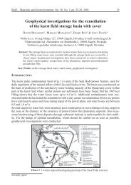
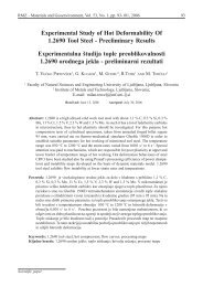
Figure 3. Schem<strong>at</strong>ic <strong>of</strong> the algorithm th<strong>at</strong> <strong>from</strong> measured final contours <strong>of</strong> deformed<br />
rods and <strong>from</strong> force-displacement d<strong>at</strong>a enables calcul<strong>at</strong>ions <strong>of</strong> <strong>stress</strong>-<strong>strain</strong> <strong>dependence</strong>,<br />
time evolution <strong>of</strong> contours and <strong>strain</strong> r<strong>at</strong>es.<br />
<strong>RMZ</strong>-M&G 2012, 59
, ) (, )<br />
(, ) 1 () + = <br />
(, )<br />
= (, )<br />
<br />
<br />
<br />
<strong>Calcul<strong>at</strong>ion</strong> <strong>of</strong> ()<br />
<strong>stress</strong>-<strong>strain</strong> ( <strong>dependence</strong> <strong>from</strong> <strong>tensile</strong> <strong>tests</strong> <strong>at</strong> high temper<strong>at</strong>ures using ...<br />
()<br />
() )<br />
<br />
( ) = <br />
)<br />
<br />
(, ) ()<br />
(, )<br />
terpol<strong>at</strong>ion function for any = ( l are calcul<strong>at</strong>ed.Finally,<br />
= (, <strong>from</strong> )<br />
(, ) Results + and (, Discussion ))<br />
1 + <br />
<br />
()<br />
<br />
the experimental <br />
<br />
results <strong>of</strong> the <strong>tensile</strong> test, which was Technical curves and contour<br />
( <br />
( )<br />
()<br />
(,<br />
conducted<br />
) + <br />
<strong>at</strong><br />
constant<br />
(, ))<br />
<br />
temper<strong>at</strong>ure, the shapes <strong>of</strong> deformed rods<br />
(<br />
true <strong>stress</strong> <br />
is determined, th<strong>at</strong> () is further = Tensile <br />
) = <br />
<br />
<br />
<br />
(, ) (, ) <br />
(, <strong>tests</strong> ) were ) carried out by uniaxial<br />
tension <strong>at</strong> prescribed displacements<br />
corrected by Bridgman formula[1].<br />
1 + <br />
<br />
<br />
Thus, we have<br />
r<strong>at</strong>es <strong>of</strong> anvils and <strong>at</strong> constant temper<strong>at</strong>ures,<br />
( where ) the tension force and dis-<br />
) = ( (, ) (, ) + ) (<br />
(, ))<br />
)<br />
( ) =<br />
<br />
<br />
<br />
( placement were continually recorded.<br />
(( ) = ))[1 + 2(( )) (( ))] ln(1 + (( )) 2(( )))<br />
After the test the contours for every deformed<br />
(( rod )) were ) carefully measured by<br />
( ) <br />
<br />
<br />
= ln( <br />
((() )) = (( ))<br />
] ln(1 (, + ) )(( )) 2((microscope. )))<br />
The number <strong>of</strong> measured<br />
= ( (, ) + (, ))<br />
<br />
points on each section <strong>of</strong> the contour<br />
<br />
(14) = <br />
= ln( (( )) <br />
( )<br />
)) 2(( )))<br />
<br />
<br />
<strong>of</strong> deformed <br />
rod depended on its local<br />
curv<strong>at</strong>ure, but it always exceeded 100<br />
and for the corresponding <strong>strain</strong> points. Obtained technical curves for<br />
= <br />
= 1 <br />
<br />
temper<strong>at</strong>ures + <br />
= = ( )<br />
<br />
<br />
))[1 + 2(( )) (( ))] ln(1 + (( )) 2(( )))<br />
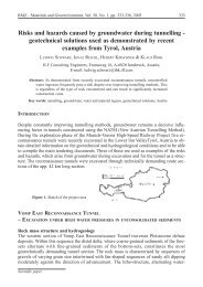
() = (800, 900, <br />
<br />
<br />
(, ))<br />
1000) °C, and<br />
(15) <strong>strain</strong> r<strong>at</strong>es <strong>of</strong> (0.001, 0.01, and 0.1) s –1<br />
<br />
with corresponding final shapes <strong>of</strong> rods<br />
= 1 = ln(<br />
<br />
<br />
Since + <br />
<br />
the <strong>dependence</strong> = (( )))<br />
<br />
<strong>of</strong> <br />
<strong>strain</strong> on time are shown in Figure 4.<br />
= (<br />
) <br />
1 + 2(( is known,<br />
)) the (( <strong>dependence</strong> )) <br />
] ln(1 + <strong>of</strong> <strong>strain</strong> ((r<strong>at</strong>e<br />
)) 2(( )))<br />
on time during the test can be easily After the transition <strong>of</strong> the m<strong>at</strong>erial<br />
= = determined as<br />
<strong>from</strong> elastic to plastic st<strong>at</strong>e the <strong>stress</strong><br />
= ln( 1 <br />
<br />
<br />
+ (( )))<br />
= remains uniaxial, but the <strong>strain</strong> is<br />
= <br />
(16) three-axial; namely the elong<strong>at</strong>ion is<br />
<br />
uniform <strong>at</strong> uniformly decreasing <strong>of</strong> diameter.<br />
Uni-axiality <strong>of</strong> the <strong>stress</strong> is pre-<br />
The computer program which takes as<br />
<br />
an input the final shape <strong>of</strong> the contour served until the occurrence <strong>of</strong> the neck.<br />
= 1 <br />
<br />
<strong>of</strong><br />
<br />
<strong>tensile</strong><br />
+ <br />
rod<br />
= and d<strong>at</strong>a<br />
<strong>from</strong> <strong>tensile</strong> During the test the measured force is<br />
test, i.e. force and length <strong>of</strong> the rod as initially increasing until it reaches the<br />
a function <strong>of</strong> time and which executes maximum, and afterwards decreasing<br />
all the above described steps and enable<br />
determin<strong>at</strong>ion <strong>of</strong> true <strong>stress</strong> – true <strong>strain</strong> where the force is <strong>at</strong> maximum<br />
up to the end <strong>of</strong> the test. The amount <strong>of</strong><br />
<strong>strain</strong> curves and time evolution <strong>of</strong> true depends on m<strong>at</strong>erial and on constitutive<br />
rel<strong>at</strong>ion σ = σ(ε, ε, T, ...) as well as<br />
.<br />
<strong>strain</strong> r<strong>at</strong>e was written in programming<br />
language C++. The schem<strong>at</strong>ic <strong>of</strong> this on changing <strong>of</strong> cross-section <strong>of</strong> specimen.<br />
Technical curve reaches the max-<br />
program and algorithm is given on Figure<br />
3.<br />
imum when dF/dl = 0, where F stands<br />
<strong>RMZ</strong>-M&G 2012, 59<br />
<br />
<br />
<br />
<br />
<br />
<br />
<br />
( ) = <br />
<br />
( )<br />
339
( )<br />
<br />
(( ))[1 + 2(( )) (( ))] ln(1 + (( )) 2(( )))<br />
( )<br />
= ln( (( )))<br />
(( ))] ln(1 + (( )) 2(( )))<br />
340 Kugler, G., Terčelj, M., Peruš, I., Turk, R.<br />
for force and l is elong<strong>at</strong>ion. From F = ing area <strong>of</strong> the rod. Since some plastic<br />
deform<strong>at</strong>ion occurs always also<br />
= <br />
(( )))<br />
σS, it follows th<strong>at</strong> <br />
<br />
outside <strong>of</strong> the working area, this contributes<br />
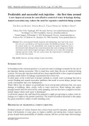
to error. Namely, the slope<br />
<br />
= <br />
= 1 <br />
<br />
+ <br />
= <br />
<strong>of</strong> the contour <strong>at</strong> boundary between<br />
(17) outside and inside area is very high.<br />
<br />
= <br />
Therefore the calcul<strong>at</strong>ed lengths <strong>of</strong><br />
rods <strong>at</strong> initial steps <strong>of</strong> deform<strong>at</strong>ion<br />
where the constancy <strong>of</strong> the volume has are too long, and cross-sections are<br />
been taken into account. Therefore the even smaller than those obtained<br />
force is maximal when dσ/dε = σ. <strong>at</strong> the end <strong>of</strong> deform<strong>at</strong>ion. Moving<br />
along the deformed contour results<br />
Form<strong>at</strong>ion <strong>of</strong> contours during in shortening <strong>of</strong> calcul<strong>at</strong>ed length<br />
<strong>strain</strong>ing<br />
as well as in increasing the minimal<br />
cross-section. According to the<br />
The key parameters th<strong>at</strong> for the selected<br />
functional model determine how present model the length <strong>of</strong> the rod<br />
accur<strong>at</strong>e the shape <strong>of</strong> contour can be initially increases with <strong>strain</strong>, which<br />
determined are the volume V o<br />
, which is nonsense. To avoid this inconsistency<br />
the contour was calcul<strong>at</strong>ed with<br />
undergo plastic deform<strong>at</strong>ion, and the<br />
local slopes <strong>of</strong> the final contour. Of our model only after the calcul<strong>at</strong>ed<br />
course, the last condition is not valid length begins to increase with <strong>strain</strong>,<br />
for the simplest i.e. cylindrical model, before th<strong>at</strong> the contour was calcul<strong>at</strong>ed<br />
assuming homogeneous defor-<br />
since the boundary conditions (7) and<br />
(8) cannot be fulfilled. Consequently, m<strong>at</strong>ion. The examples <strong>of</strong> calcul<strong>at</strong>ion<br />
the shapes <strong>of</strong> contours calcul<strong>at</strong>ed by <strong>of</strong> the rod shapes evolution during<br />
cylindrical model are unrealistic (see deform<strong>at</strong>ion for cylinder and for c<strong>at</strong>enary<br />
<strong>at</strong> temper<strong>at</strong>ures 1000 °C and<br />
Figures. 5a and c), but nevertheless, as<br />
it will be demonstr<strong>at</strong>ed l<strong>at</strong>er, this model<br />
gives surprisingly good prediction 0.1 s –1 are shown on Figure 5. If one<br />
900 °C, and prescribed <strong>strain</strong> r<strong>at</strong>e <strong>of</strong><br />
<strong>of</strong> the evolution <strong>of</strong> the minimal radius wants to calcul<strong>at</strong>e the <strong>dependence</strong><br />
<strong>of</strong> the rod within the neck during entire <strong>of</strong> true <strong>stress</strong> on <strong>strain</strong>, the minimal<br />
<strong>tensile</strong> test.<br />
cross-section, which is obtained <strong>from</strong><br />
reconstruction <strong>of</strong> contour <strong>of</strong> the rod,<br />
As we mentioned earlier the volume, must be given for every <strong>strain</strong>. The<br />
V o<br />
, is obtained by integr<strong>at</strong>ion <strong>of</strong> the <strong>dependence</strong> <strong>of</strong> minimal radius on<br />
final contour <strong>of</strong> the rod along the z- elong<strong>at</strong>ion for two temper<strong>at</strong>ures calcul<strong>at</strong>ed<br />
by c<strong>at</strong>enary model is given<br />
axis considering condition r(z) ≤ r o<br />
,<br />
where r o<br />
is initial radius <strong>of</strong> the work-<br />
on Figures 6a and 6b.<br />
<strong>RMZ</strong>-M&G 2012, 59
<strong>Calcul<strong>at</strong>ion</strong> <strong>of</strong> <strong>stress</strong>-<strong>strain</strong> <strong>dependence</strong> <strong>from</strong> <strong>tensile</strong> <strong>tests</strong> <strong>at</strong> high temper<strong>at</strong>ures using ...<br />
341<br />
Figure 4. Technical curves force-elong<strong>at</strong>ion obtained wit <strong>tensile</strong> <strong>tests</strong> for <strong>strain</strong> r<strong>at</strong>es<br />
<strong>of</strong> (0.001, 0.01 and 0.1) s –1 <strong>at</strong> temper<strong>at</strong>ures <strong>of</strong> 800 °C (a), 900 °C (b), and 1000 °C (c)<br />
together with corresponding measured final shapes <strong>of</strong> deformed rods (d)–(f).<br />
Figure 5. The calcul<strong>at</strong>ed shapes <strong>of</strong> <strong>tensile</strong> rods for various stages <strong>of</strong> deform<strong>at</strong>ions <strong>at</strong><br />
temper<strong>at</strong>ure <strong>of</strong> 1000 °C and <strong>strain</strong> r<strong>at</strong>e <strong>of</strong> 0.1 s –1 for cylindrical (a) and for c<strong>at</strong>enary<br />
model (b). <strong>Calcul<strong>at</strong>ion</strong> for cylindrical (c) and c<strong>at</strong>enary (d) models <strong>at</strong> T = 900 °C and<br />
<strong>strain</strong> r<strong>at</strong>e <strong>of</strong> 0.1 s –1 .<br />
<strong>RMZ</strong>-M&G 2012, 59
342 Kugler, G., Terčelj, M., Peruš, I., Turk, R.<br />
Figure 6. Comparison <strong>of</strong> <strong>dependence</strong> <strong>of</strong> minimal radius <strong>of</strong> deformed rod on elong<strong>at</strong>ion<br />
calcul<strong>at</strong>ed by models for c<strong>at</strong>enary, cylinder, and for assumption <strong>of</strong> homogeneous deform<strong>at</strong>ion<br />
for ε = 0.1 s –1 <strong>at</strong> T = 1000 °C (a), and T = 900 °C (b). Evolution <strong>of</strong> the radius <strong>of</strong><br />
.<br />
the circle oscul<strong>at</strong>ing the pr<strong>of</strong>ile <strong>at</strong> the neck, R B<br />
, and corresponding <strong>dependence</strong> <strong>of</strong> Bridgman<br />
correction coefficient, k B<br />
, on elong<strong>at</strong>ion calcul<strong>at</strong>ed by c<strong>at</strong>enary model <strong>at</strong> T = 1000<br />
°C (c), and T = 900 °C (d).<br />
Figure 7. Comparison <strong>of</strong> <strong>dependence</strong> <strong>of</strong> minimal radiuses on elong<strong>at</strong>ion between measurements<br />
conducted by digital camera and calcul<strong>at</strong>ed by studied models (c<strong>at</strong>enary, cylinder,<br />
homogeneous deform<strong>at</strong>ion) for ε = 0.1 s –1 <strong>at</strong> T = 950 °C (a), and <strong>at</strong> T = 900 °C (b).<br />
.<br />
<strong>RMZ</strong>-M&G 2012, 59
<strong>Calcul<strong>at</strong>ion</strong> <strong>of</strong> <strong>stress</strong>-<strong>strain</strong> <strong>dependence</strong> <strong>from</strong> <strong>tensile</strong> <strong>tests</strong> <strong>at</strong> high temper<strong>at</strong>ures using ...<br />
343<br />
For comparison the minimal radiuses<br />
calcul<strong>at</strong>ed by cylindrical model and by<br />
assumption <strong>of</strong> homogeneous deform<strong>at</strong>ion<br />
are also given. It can be seen th<strong>at</strong><br />
the radius obtained by cylindrical model<br />
is very close to one obtained by c<strong>at</strong>enary,<br />
whereas as expected the radius<br />
according to homogenous deform<strong>at</strong>ion<br />
model after occurrence <strong>of</strong> necking start<br />
do devi<strong>at</strong>e <strong>from</strong> values predicted by our<br />
models. Deform<strong>at</strong>ion is homogeneous<br />
approxim<strong>at</strong>ely up to elong<strong>at</strong>ion <strong>of</strong> 2<br />
mm th<strong>at</strong> corresponds to <strong>strain</strong> ≈0.2. As<br />
it was already mentioned, the transition<br />
<strong>from</strong> homogeneous to nonhomogeneous<br />
deform<strong>at</strong>ion leads to transition <strong>of</strong><br />
uniaxial to three-axial <strong>stress</strong> st<strong>at</strong>e. For<br />
calcul<strong>at</strong>ion <strong>of</strong> Bridgman correction, k B<br />
,<br />
the radius <strong>of</strong> the circle oscul<strong>at</strong>ing the<br />
pr<strong>of</strong>ile <strong>at</strong> the neck, R B<br />
, is needed. The<br />
R B<br />
is calcul<strong>at</strong>ed by equ<strong>at</strong>ion (10) <strong>from</strong><br />
reconstructed contours. The evolution<br />
<strong>of</strong> R B<br />
and k B<br />
are given on Figure 6c,<br />
and 6d, respectively. When the contours<br />
are calcul<strong>at</strong>ed by the homogeneous<br />
deform<strong>at</strong>ion model, we set k B<br />
≡ 1,<br />
consequently the <strong>dependence</strong> <strong>of</strong> k B<br />
(Δl)<br />
is discontinued <strong>at</strong> transition between<br />
both areas, with negligible error.<br />
Calcul<strong>at</strong>ed values <strong>of</strong> the time evolution<br />
<strong>of</strong> the minimal radius <strong>of</strong> the <strong>tensile</strong><br />
specimens were compared with<br />
the values obtained <strong>from</strong> analysis <strong>of</strong><br />
the pictures which were recorded by<br />
a digital camera, and we obtained reasonable<br />
agreement. These results are<br />
shown on Figure 7, were the maximal<br />
estim<strong>at</strong>ed errors for minimal radius<br />
measured with camera are denoted.<br />
Due to intensive radi<strong>at</strong>ion <strong>from</strong> hot<br />
samples, the sharp boundary between<br />
the rod and surrounding was indistinct,<br />
thus the determin<strong>at</strong>ion <strong>of</strong> real minimal<br />
radius was hindered.<br />
True <strong>stress</strong>–true <strong>strain</strong> curves<br />
From technical force-elong<strong>at</strong>ion<br />
curves the true <strong>stress</strong>–true <strong>strain</strong> curves<br />
were determined by employing all the<br />
procedures explained in previous sections.<br />
They are shown on Figures 8a–c,<br />
whereas Figures 8d–e show the actual<br />
vari<strong>at</strong>ion <strong>of</strong> <strong>strain</strong> r<strong>at</strong>es during the <strong>tests</strong>.<br />
For higher temper<strong>at</strong>ures and/or lower<br />
<strong>strain</strong> r<strong>at</strong>es the flow <strong>stress</strong> initially<br />
raises until a maximum is reached<br />
when hardening and s<strong>of</strong>tening are in<br />
balance. With increasing deform<strong>at</strong>ion,<br />
s<strong>of</strong>tening prevails over hardening and<br />
flow <strong>stress</strong> decreases. At <strong>strain</strong>s ε ><br />
0.2 flow <strong>stress</strong> starts to increase and<br />
increases until the end <strong>of</strong> the experiment.<br />
This kind <strong>of</strong> behaviour in the<br />
l<strong>at</strong>er stages <strong>of</strong> deform<strong>at</strong>ion is a consequence<br />
<strong>of</strong> the continuously increasing<br />
<strong>strain</strong> r<strong>at</strong>e after the appearance<br />
<strong>of</strong> necking. For the same reason flow<br />
curves for low temper<strong>at</strong>ures and/or<br />
higher <strong>strain</strong> r<strong>at</strong>es do not reach a maximum.<br />
Thus, we can conclude th<strong>at</strong><br />
after necking, the <strong>stress</strong>-<strong>strain</strong> curves<br />
are not flow curves as by definition<br />
flow curves are <strong>stress</strong>-<strong>strain</strong> curves <strong>at</strong><br />
constant temper<strong>at</strong>ure and <strong>strain</strong> r<strong>at</strong>e.<br />
<strong>RMZ</strong>-M&G 2012, 59
344 Kugler, G., Terčelj, M., Peruš, I., Turk, R.<br />
Figure 8. True <strong>stress</strong>-true <strong>strain</strong> curves, obtained by <strong>tensile</strong> <strong>tests</strong> for prescribed <strong>strain</strong><br />
r<strong>at</strong>es <strong>of</strong> (0.001, 0.01) s –1 , and 0.1 s –1 <strong>at</strong> temper<strong>at</strong>ures <strong>of</strong> 800 °C (a), 900 °C (b), and 1000<br />
°C (c) and corresponding vari<strong>at</strong>ion <strong>of</strong> actual <strong>strain</strong> r<strong>at</strong>e during the <strong>tests</strong> (d)–(f).<br />
But in the future a series <strong>of</strong> carefully<br />
chosen testing conditions is planed<br />
with the aim to examine the possibility<br />
<strong>of</strong> finding the model th<strong>at</strong> would the<br />
movements <strong>of</strong> jaws during the <strong>tests</strong> in<br />
such a way th<strong>at</strong> constant true <strong>strain</strong> r<strong>at</strong>e<br />
would be maintained during the entire<br />
test. Then it would be possible to determine<br />
flow curves with <strong>tensile</strong> testing to<br />
<strong>strain</strong>s th<strong>at</strong> are comparable with <strong>strain</strong>s<br />
th<strong>at</strong> can be obtained with compression<br />
testing.<br />
Conclusions<br />
In this work a new m<strong>at</strong>hem<strong>at</strong>ical model<br />
for calcul<strong>at</strong>ion <strong>of</strong> true <strong>stress</strong> – true<br />
<strong>strain</strong> <strong>dependence</strong> <strong>from</strong> the results <strong>of</strong><br />
<strong>tensile</strong> <strong>tests</strong>, which can be used also<br />
after appearing <strong>of</strong> necking, was proposed.<br />
Furthermore the model was implemented<br />
into the computer program<br />
th<strong>at</strong> enables determin<strong>at</strong>ion <strong>of</strong> <strong>stress</strong><strong>strain</strong><br />
curves <strong>from</strong> measurement <strong>of</strong><br />
contours <strong>of</strong> deformed rods. The model<br />
and the computer program were valid<strong>at</strong>ed<br />
by employing <strong>tensile</strong> <strong>tests</strong> for<br />
combin<strong>at</strong>ions <strong>of</strong> three different <strong>strain</strong><br />
r<strong>at</strong>es and temper<strong>at</strong>ures on Gleeble<br />
1500D testing machine for Ni alloy Alloy201.<br />
The main findings can be summarized<br />
as follows:<br />
1. It was found th<strong>at</strong>, if the jaws <strong>of</strong> testing<br />
device are controlled in such a<br />
way th<strong>at</strong> constant <strong>strain</strong> r<strong>at</strong>e is obtained<br />
if homogeneous deform<strong>at</strong>ion<br />
is assumed, after appearance<br />
<strong>of</strong> necking the true <strong>strain</strong> r<strong>at</strong>e is no<br />
longer constant, but it is increasing.<br />
Thus, <strong>stress</strong>-<strong>strain</strong> curves obtained<br />
in this way are not true flow<br />
<strong>RMZ</strong>-M&G 2012, 59
<strong>Calcul<strong>at</strong>ion</strong> <strong>of</strong> <strong>stress</strong>-<strong>strain</strong> <strong>dependence</strong> <strong>from</strong> <strong>tensile</strong> <strong>tests</strong> <strong>at</strong> high temper<strong>at</strong>ures using ...<br />
345<br />
curves, as by definition flow curves<br />
are <strong>stress</strong>-<strong>strain</strong> curves <strong>at</strong> a constant<br />
<strong>strain</strong> r<strong>at</strong>e.<br />
2. In the present work two functions<br />
for description <strong>of</strong> evolution <strong>of</strong> the<br />
part <strong>of</strong> the contour which is in given<br />
moment in the plastic st<strong>at</strong>e, were<br />
tested, i.e. constant (approxim<strong>at</strong>ion<br />
with cylinder) and c<strong>at</strong>enary. Based<br />
on the comparison <strong>of</strong> the predicted<br />
evolution <strong>of</strong> contour and contours<br />
obtained by measurements with<br />
film camera it was found th<strong>at</strong> both<br />
functions are capable <strong>of</strong> description<br />
<strong>of</strong> evolution <strong>of</strong> minimal radius<br />
<strong>of</strong> the rod in the neck with accuracy<br />
within the measurement error.<br />
3. The main problem <strong>of</strong> applying the<br />
simplest function, i.e. the constant,<br />
is th<strong>at</strong> it is not possible to determine<br />
the evolution <strong>of</strong> radius <strong>of</strong> curv<strong>at</strong>ure<br />
<strong>of</strong> the couture <strong>at</strong> the minimal<br />
cross-section and consequently<br />
Bridgman <strong>stress</strong> correction due to<br />
three-axiality <strong>of</strong> the <strong>stress</strong> cannot<br />
be applied since for constant this<br />
curv<strong>at</strong>ure is infinite. On the other<br />
hand using c<strong>at</strong>enary this problem is<br />
avoided and true <strong>stress</strong> – true <strong>strain</strong><br />
curves including Bridgman correction<br />
can be determined.<br />
4. It could be possible to predetermine<br />
the movements <strong>of</strong> jaws during the<br />
<strong>tests</strong> in such a way th<strong>at</strong> constant true<br />
<strong>strain</strong> r<strong>at</strong>e would be maintained during<br />
the entire test or <strong>at</strong> least up to<br />
the true <strong>strain</strong>s up to the value <strong>of</strong> 1.0,<br />
but this will require many more <strong>tests</strong><br />
for different m<strong>at</strong>erials and <strong>at</strong> different<br />
thermo-mechanical conditions.<br />
References<br />
[1]<br />
Bridgman, P. W. (1952): Studies in<br />
Large Plastic Flow and Fracture,<br />
McGraw-Hill, NY.<br />
[2]<br />
Press, W. H. et. al. (1988): Numerical<br />
recipes in C, Cambridge Univrsity<br />
Press, Cambridge.<br />
[3]<br />
Kugler, G. (2004): Prediction <strong>of</strong> hot<br />
workability <strong>of</strong> metals by use <strong>of</strong>cellular<br />
autom<strong>at</strong>a, Univrsity <strong>of</strong> Ljubljana,<br />
NTF, Ljubljana.<br />
[4]<br />
Turk, R. (1982):Postavitev modela za<br />
oceno tople preoblikovalnosti kovin,<br />
Univerza v Ljubljani, FNT, Ljubljana.<br />
<strong>RMZ</strong>-M&G 2012, 59