18SP546* œ Install DDEC II to DDEC IV Wire Harness and ... - ddcsn
18SP546* œ Install DDEC II to DDEC IV Wire Harness and ... - ddcsn
18SP546* œ Install DDEC II to DDEC IV Wire Harness and ... - ddcsn

Create successful ePaper yourself
Turn your PDF publications into a flip-book with our unique Google optimized e-Paper software.
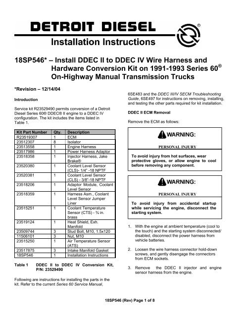
<strong>18SP546*</strong> – <strong>Install</strong> <strong>DDEC</strong> <strong>II</strong> <strong>to</strong> <strong>DDEC</strong> <strong>IV</strong> <strong>Wire</strong> <strong>Harness</strong> <strong>and</strong><br />
Hardware Conversion Kit on 1991-1993 Series 60 ®<br />
On-Highway Manual Transmission Trucks<br />
*Revision – 12/14/04<br />
Introduction<br />
Service kit R23529490 permits conversion of a Detroit<br />
Diesel Series 60® <strong>DDEC</strong>® <strong>II</strong> engine <strong>to</strong> a <strong>DDEC</strong> <strong>IV</strong><br />
configuration. The kit includes the items listed in<br />
Table 1.<br />
Kit Part Number Qty. Description<br />
R23519307 1 ECM<br />
23512307 8 Isola<strong>to</strong>r<br />
23513558 1 Engine <strong>Harness</strong><br />
23517986 1 Power <strong>Harness</strong> Adap<strong>to</strong>r<br />
23518358 1 Injec<strong>to</strong>r <strong>Harness</strong>, Jake<br />
Brake®<br />
23520380 1 Coolant Level Sensor<br />
(CLS)- 1/4” -18 NPTF<br />
23520381 1 Coolant Level Sensor<br />
(CLS) - 3/8”-18 NPTF<br />
23518206 1 Adap<strong>to</strong>r Module, Coolant<br />
Level Sensor<br />
23518359 1 <strong>Harness</strong> Asm., Coolant<br />
Level Sensor Jumper<br />
Liner<br />
23515251 1 Coolant Temperature<br />
Sensor (CTS) - ¾ in.<br />
brass<br />
23519124 1 Heat Shield, Exh.<br />
Manifold<br />
23509744 3 Stud Bolt, M10, 1.5x120<br />
11506101 3 Nut, M10<br />
23515250 1 Air Temperature Sensor<br />
(ATS)<br />
23517875 3 Intake Manifold Gasket<br />
18SP546 1 <strong>Install</strong>ation Instructions<br />
Table 1<br />
<strong>DDEC</strong> <strong>II</strong> <strong>to</strong> <strong>DDEC</strong> <strong>IV</strong> Conversion Kit,<br />
P/N: 23529490<br />
Following are instructions for installing the parts in the<br />
kit. Refer <strong>to</strong> the current Series 60 Service Manual,<br />
6SE483 <strong>and</strong> the <strong>DDEC</strong> <strong>II</strong>I/<strong>IV</strong> SECM Troubleshooting<br />
Guide, 6SE497 for instructions on removing, installing,<br />
<strong>and</strong> testing the other parts required for kit installation.<br />
<strong>DDEC</strong> <strong>II</strong> ECM Removal<br />
Remove the ECM as follows:<br />
PERSONAL INJURY<br />
To avoid injury from hot surfaces, wear<br />
protective gloves, or allow engine <strong>to</strong> cool<br />
before removing any component.<br />
PERSONAL INJURY<br />
To avoid injury from accidental startup<br />
while servicing the engine, disconnect the<br />
starting system.<br />
1. With the engine at ambient temperature (cool <strong>to</strong><br />
the <strong>to</strong>uch) <strong>and</strong> the starting system disconnected/<br />
disabled, disconnect the power harness from<br />
vehicle batteries.<br />
2. Loosen the wire harness connec<strong>to</strong>r hold-down<br />
screws, <strong>and</strong> gently disengage the connec<strong>to</strong>rs<br />
from ECM sockets.<br />
3. Remove the <strong>DDEC</strong> <strong>II</strong> injec<strong>to</strong>r <strong>and</strong> engine<br />
sensor harness from the engine.<br />
18SP546 (Rev) Page 1 of 8
4. Loosen the wire harness connec<strong>to</strong>r hold-down<br />
screws, gently disengage connec<strong>to</strong>rs, <strong>and</strong><br />
remove <strong>DDEC</strong> <strong>II</strong> ECM from vehicle.<br />
<strong>DDEC</strong> <strong>IV</strong> ECM <strong>Install</strong>ation<br />
Conversion kit components are listed in Table 1. Refer<br />
<strong>to</strong> the Series 60 Service Manual <strong>and</strong> install parts as<br />
follows:<br />
1. <strong>Install</strong> the Engine Sensor <strong>Harness</strong> (P/N:<br />
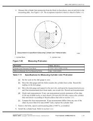
23513558), included in the kit. See Figure 1. Refer<br />
<strong>to</strong> Section 8.6 of Service Manual.<br />
2. <strong>Install</strong> the Injec<strong>to</strong>r/Jake Brake® harness<br />
(P/N: 23518358) included in the kit.<br />
3. <strong>Install</strong> new Coolant Level Sensor (CLS) (either ¼”<br />
P/N: 23520380 or 3/8” P/N; 23520381). Refer <strong>to</strong><br />
Section 2.34 of Service Manual.<br />
PERSONAL INJURY<br />
Diesel engine exhaust <strong>and</strong> some of its<br />
constituents are known <strong>to</strong> the State of<br />
California <strong>to</strong> cause cancer, birth defects,<br />
<strong>and</strong> other reproductive harm.<br />
• Always start <strong>and</strong> operate an engine in<br />
a well ventilated area.<br />
• If operating an engine in an enclosed<br />
area, vent the exhaust <strong>to</strong> the outside.<br />
• Do not modify or tamper with the<br />
exhaust system or emission control<br />
system.<br />
12. Reconnect starting power. Start the engine <strong>and</strong><br />
check for proper <strong>DDEC</strong> system operation.<br />
4. <strong>Install</strong> the CLS adap<strong>to</strong>r module (P/N: 23518206)<br />
<strong>and</strong> jumper adap<strong>to</strong>r (P/N: 23518359).<br />
5. <strong>Install</strong> the Coolant Temperature Sensor (CTS)<br />
(P/N: 23515251) at right rear of head. Refer <strong>to</strong><br />
Section 2.31 of Service Manual.<br />
6. <strong>Install</strong> the heat shield (P/N: 23519124) using stud<br />
bolts (P/N: 23509744) <strong>and</strong> nuts (P/N: 11506101).<br />
a) If the engine has current exhaust manifold,<br />
install heat shield “as is.”<br />
b) If the engine has former style manifold, the heat<br />
shield may need <strong>to</strong> be altered prior <strong>to</strong><br />
installation.<br />
7. Remove the air intake manifold <strong>and</strong> discard old<br />
gaskets.<br />
8. Using a drill press <strong>and</strong> a 9/16” drill, drill <strong>and</strong> tap a<br />
3/8” pipe port for the Air Temperature Sensor<br />
(ATS), between #3 <strong>and</strong> #4 intake air ports in<br />
manifold. See Figure 2.<br />
9. Clean the air intake manifold thoroughly <strong>to</strong> remove<br />
drill chaff.<br />
10. <strong>Install</strong> ATS (P/N: 23515250). Torque <strong>to</strong> 11-16 N·m<br />
(8-12 lb·ft).<br />
11. Using new gaskets (P/N: 23517875), install the air<br />
intake manifold.<br />
Figure 1<br />
Figure 2<br />
<strong>DDEC</strong> <strong>IV</strong> ECM <strong>and</strong> Wiring <strong>Harness</strong><br />
Locations<br />
Air Temperature Sensor Location<br />
18SP546 (Rev) Page 2 of 8
Powernet Engine Order Entry,<br />
Change Unit Information<br />
In order for the newly installed <strong>DDEC</strong> <strong>IV</strong> ECM <strong>to</strong> be<br />
programmed, a mainframe file must be established. To<br />
ensure that the ability <strong>to</strong> program the <strong>DDEC</strong> <strong>IV</strong> ECM is<br />
established, the attached FAX form (See Figure 5) must<br />
be filled out <strong>and</strong> sent <strong>to</strong> the DDC Cus<strong>to</strong>mer Support<br />
Center at (313) 592-5888. See Table 2 for the<br />
appropriate 6N4D <strong>and</strong> 6N4M groups.<br />
Important Information – Please read.<br />
You must use the updated fax request in these<br />
instructions, or request the mainframe update <strong>to</strong> “<strong>DDEC</strong><br />
<strong>IV</strong>,” otherwise the wrong calibration could be assigned.<br />
The <strong>DDEC</strong> <strong>IV</strong> ECM in this kit is only for use with<br />
12-volt systems.<br />
Within the ratings listed, you will find the original <strong>DDEC</strong><br />
<strong>II</strong>-<strong>II</strong>I ratings <strong>and</strong> a cross-reference <strong>to</strong> the comparable<br />
<strong>DDEC</strong> <strong>IV</strong> version.<br />
With the following features now found within the <strong>DDEC</strong><br />
system, it is possible <strong>to</strong> cover a wide variety of requests<br />
with fewer ratings:<br />
• Low gear <strong>to</strong>rque limiting will modify the max.<br />
<strong>to</strong>rque for the application.<br />
• Progressive shift will limit the max RPM for the<br />
user.<br />
NOTE:<br />
Vehicle speed sensors must be used for these two<br />
features <strong>to</strong> operate properly.<br />
For example, there is only one <strong>DDEC</strong> <strong>IV</strong> rating released<br />
for the 11 liter engines: 6N4D7275 is a 400/357 @<br />
1800/2100-1350 lb·ft.<br />
To reduce the maximum <strong>to</strong>rque from 1350 <strong>to</strong> 1250 lb·ft:<br />
• Set the low gear <strong>to</strong>rque limit <strong>to</strong> 1250<br />
• Set the threshold <strong>to</strong> 0.1<br />
To reduce the maximum rated speed from 2100 <strong>to</strong><br />
1800 rpm, set progressive shift as follows:<br />
• LG1 rpm limit - 1800<br />
• LG1 max rpm - 1800<br />
• LG1 max mph - 12<br />
• LG2 rpm limit - 1800<br />
• LG2 max rpm - 1800<br />
• LG2 max mph - 44<br />
• HG max rph - 1800<br />
• HG min mph - 45<br />
<strong>DDEC</strong> <strong>II</strong> <strong>to</strong> <strong>DDEC</strong> <strong>IV</strong> UPC groups are listed in Table 2.<br />
To ensure that the engine is serviced properly after<br />
being converted from <strong>DDEC</strong> <strong>II</strong> <strong>to</strong> <strong>DDEC</strong> <strong>IV</strong>, <strong>and</strong> <strong>to</strong><br />
ensure that other modifications may be made, DDC’s<br />
unit his<strong>to</strong>ry file must be updated. If this is not done,<br />
subsequent engine service <strong>and</strong>/or repair work might be<br />
done using incorrect parts. Complete the attached FAX<br />
form <strong>and</strong> send it <strong>to</strong> the DDC Cus<strong>to</strong>mer Support Center.<br />
See Figure 5.<br />
18SP546 (Rev) Page 3 of 8
<strong>DDEC</strong> <strong>IV</strong> <strong>DDEC</strong> <strong>II</strong>/<strong>II</strong>I CWC Rated @RPM Other @RPM FT·LB @RPM Inj. P/N Inj. P/N<br />
HP<br />
HP<br />
6N4D-7275 6N4D-6309 5234935 5235605<br />
N/A 6N4M-6149 235 350 1800 1250 1200<br />
N/A 6N4M-6153 239 320 1800 1250 1200<br />
N/A 6N4M-6167 354 320/350 1800 1250 1200<br />
6N4D-7275 6N4D-6310 5234935 5235605<br />
N/A 6N4M-6214 414 365 1800 1350 1200<br />
N/A 6N4M-6215 413 350 1800 1350 1200<br />
N/A 6N4M-6203 371 325 1800 1350 1200<br />
N/A 6N4M-6216 415 325/350 1800 1350 1200<br />
6N4D-7275 6N4D-6311 5234935 5235605<br />
N/A 6N4M-6154 240 320 1800 1150 1200<br />
N/A 6N4M-6157 243 285 1800 1150 1200<br />
N/A 6N4M-6371 478 285/320 1800 1150 1200<br />
6N4D-7275 6N4D-6312 5234935 5235605<br />
N/A 6N4M-6148 234 320 2100 350 1800 1250 1200<br />
6N4D-7275 6N4D-7127 5234935 5235605<br />
6N4M-7815 6N4M-6916 1261 357 2100 400 1800 1350 1200<br />
6N4D-7274 6N4D-6313 5234935 5235605<br />
6N4M-7811 6N4M-6374 433 450 2100-1800 1450 1500-1200<br />
6N4M-7812 6N4M-6211 416 430 2100-1800 1450 1500-1200<br />
6N4M-7813 6N4M-6200 253 425 2100-1800 1450 1200<br />
6N4M-7814 6N4M-6372 479 425/450 2100-1800 1450 1200<br />
6N4D-7272 6N4D-6314 5234970 5235695<br />
6N4M-7804 6N4M-6212 417 430 1800 1450 1500-1200<br />
6N4M-7805 6N4M-6164 250 400 1800 1450 1200<br />
6N4M-7806 6N4M-6166 252 365 1800 1450 1200<br />
N/A 6N4M-6213 359 365/400 1800 1450 1200<br />
6N4D-7272 6N4D-6315 5234940 5235600<br />
6N4M-7804 6N4M-6212 417 430 1800 1450 1500-1200<br />
6N4M-7805 6N4M-6164 250 400 1800 1450 1200<br />
6N4M-7806 6N4M-6166 252 365 1800 1450 1200<br />
6N4M-7807 6N4M-6213 418 365/430 1800 1450 1200<br />
6N4D-7273 6N4D-6316 5234940 5235600<br />
6N4M-7808 6N4M-6161 247 400 2100 425 1800 1450 1200<br />
6N4M-7809 6N4M-6165 251 365 2100 1450 1200<br />
6N4M-7810 6N4M-6202 373 365/400 2100 1450 1200<br />
Table 2<br />
1991-1993 Series 60 <strong>DDEC</strong> <strong>II</strong> <strong>to</strong> <strong>DDEC</strong> <strong>IV</strong> Conversion – On-Highway Trucks with Manual<br />
Transmissions<br />
18SP546 (Rev) Page 4 of 8
<strong>DDEC</strong> <strong>II</strong> <strong>to</strong> <strong>DDEC</strong> <strong>IV</strong> Conversion Cruise Control<br />
Switch Wiring Modifications<br />
Figure 3 illustrates a typical <strong>DDEC</strong> <strong>II</strong> cruise control wiring<br />
schematic. Wiring modifications <strong>to</strong> the Cruise Enable<br />
Switch <strong>and</strong> the Set/Coast Switch are required whenever<br />
a <strong>DDEC</strong> <strong>II</strong> <strong>to</strong> <strong>DDEC</strong> <strong>IV</strong> conversion is made on a vehicle<br />
using the <strong>DDEC</strong> <strong>II</strong> cruise control feature.<br />
Figure 4<br />
Cruise Control Wiring Schematic after<br />
Modification<br />
Testing of Cruise Control Switch <strong>and</strong> Wiring<br />
Figure 3<br />
Typical <strong>DDEC</strong> <strong>II</strong> Cruise Control Wiring<br />
Schematic<br />
Remove the wire identified as <strong>DDEC</strong> circuit #542 from<br />
the Set/Coast Switch. At a convenient point, splice circuit<br />
#542 in<strong>to</strong> the cruise control switched ground circuit.<br />
Cruise control switched ground is the circuit that is<br />
“open” when the Cruise Enable Switch is turned OFF<br />
<strong>and</strong> “grounded” when the Cruise Enable Switch is turned<br />
ON. If necessary, use a volt-ohm meter <strong>to</strong> verify the<br />
circuit before splicing in circuit #542. Depending on the<br />
application, the switched ground circuit may be identified<br />
as <strong>DDEC</strong> circuit #558 or a branch of <strong>DDEC</strong> battery<br />
ground, such as circuit #953A, #953B, or #953C, etc.<br />
See Figure 4.<br />
To speed up the testing of cruise control switches, quick<br />
check tables have been developed. These tests are <strong>to</strong><br />
be run with the ignition ON, <strong>and</strong> the engine not running.<br />
A DDR / DDDL must be plugged in<strong>to</strong> the connec<strong>to</strong>r. All<br />
three quick check tables must be completed <strong>to</strong> properly<br />
check the cruise control wiring <strong>and</strong> switches.<br />
See Tables 3, 4 <strong>and</strong> 5.<br />
NOTE:<br />
When all tests pass, the unit is ready for road testing.<br />
LOSS OF VEHICLE CONTROL<br />
To avoid injury from the loss of vehicle control, do<br />
Not use cruise control under these conditions:<br />
• When it is not possible <strong>to</strong> keep the<br />
vehicle at a constant speed (on winding<br />
roads, in heavy traffic, in traffic that varies<br />
in speed, etc.)<br />
• On slippery roads (wet pavement, ice-or<br />
snow-covered roads, loose gravel, etc.)<br />
18SP546 (Rev) Page 5 of 8
Step<br />
Cruise Enable<br />
Switch<br />
Set/<br />
Coast<br />
Switch<br />
Res/<br />
Accel<br />
Switch<br />
DDR/DDDL<br />
Readout<br />
DDR/DDDL<br />
Display<br />
Okay<br />
?<br />
Go To<br />
1 Off Off Off<br />
Off Yes —<br />
Cruise<br />
Enable<br />
Refer <strong>to</strong> Sec. 10.7 of <strong>DDEC</strong><br />
On No<br />
<strong>II</strong>I/<strong>IV</strong> SECM TS Manual<br />
2 On Off Off<br />
Refer <strong>to</strong> Sec. 10.7 of <strong>DDEC</strong><br />
Cruise Off No<br />
<strong>II</strong>I/<strong>IV</strong> SECM TS Manual<br />
Enable<br />
On Yes —<br />
Table 3 Cruise Control Quick Check Table, Testing Cruise Enable Switch <strong>and</strong> Wiring<br />
Step<br />
Cruise Enable<br />
Switch<br />
Brake<br />
Pedal<br />
Clutch<br />
Pedal<br />
1 On Released Released<br />
2 On Depressed Released<br />
3 On Released Released<br />
4 On Released Depressed<br />
Table 4<br />
DDR/DDDL<br />
Readout<br />
Service<br />
Brake<br />
Release<br />
Service<br />
Brake<br />
Release<br />
DDR/DDDL Okay<br />
Display ?<br />
Go To<br />
On Yes —<br />
Refer <strong>to</strong> Sec. 10.7 of<br />
Off No <strong>DDEC</strong> <strong>II</strong>I/<strong>IV</strong> SECM<br />
TS Manual<br />
Refer <strong>to</strong> Sec. 10.7 of<br />
On No <strong>DDEC</strong> <strong>II</strong>I/<strong>IV</strong> SECM<br />
TS Manual<br />
Off Yes —<br />
On Yes —<br />
Refer <strong>to</strong> Sec. 10.7 of<br />
<strong>DDEC</strong> <strong>II</strong>I/<strong>IV</strong> SECM<br />
TS Manual<br />
Clutch<br />
Release Off No<br />
Clutch<br />
Release<br />
On<br />
No<br />
Refer <strong>to</strong> Sec. 10.7 of<br />
<strong>DDEC</strong> <strong>II</strong>I/<strong>IV</strong> SECM<br />
TS Manual<br />
Off Yes —<br />
Cruise Control Quick Check Table, Testing Brake <strong>and</strong> Clutch Switch <strong>and</strong> Wiring<br />
Step<br />
Cruise Enable<br />
Switch<br />
Set/<br />
Coast<br />
Switch<br />
Res/<br />
Accel<br />
Switch<br />
1 On Off Off<br />
2 On On Off<br />
3 On Off Off<br />
4 On Off On<br />
Table 5<br />
DDR/DDDL<br />
Readout<br />
Set/Coast<br />
Set/Coast<br />
Res/Accel<br />
Res/Accel<br />
DDR/DDDL<br />
Display<br />
Okay<br />
?<br />
Go To<br />
Off Yes —<br />
On No<br />
Refer <strong>to</strong> Sec. 10.7 of <strong>DDEC</strong> <strong>II</strong>I/<strong>IV</strong><br />
SECM TS Manual<br />
Off No<br />
Refer <strong>to</strong> Sec. 10.7 of <strong>DDEC</strong> <strong>II</strong>I/<strong>IV</strong><br />
SECM TS Manual<br />
On Yes —<br />
Cruise Control Quick Check Table, Testing Set/Coast <strong>and</strong> Resume/Accel Switches <strong>and</strong> Wiring<br />
18SP546 (Rev) Page 6 of 8
Figure 5<br />
18SP546 (Rev) Page 7 of 8
Copyright© 2004 Detroit Diesel Corporation. Detroit Diesel ® , DDC ® , Series 60 ® , <strong>and</strong> the spinning arrows design are registered trademarks of<br />
Detroit Diesel Corporation. All other trademarks are the property of their respective owners.<br />
18SP546 (Rev.) 0412 As technical advances continue, specifications will change. All rights reserved. Printed in U.S.A.<br />
18SP546 (Rev) Page 8 of 8