18SP546* œ Install DDEC II to DDEC IV Wire Harness and ... - ddcsn
18SP546* œ Install DDEC II to DDEC IV Wire Harness and ... - ddcsn
18SP546* œ Install DDEC II to DDEC IV Wire Harness and ... - ddcsn

Create successful ePaper yourself
Turn your PDF publications into a flip-book with our unique Google optimized e-Paper software.
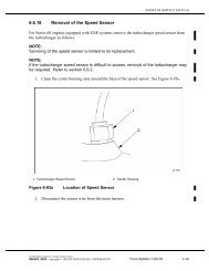
4. Loosen the wire harness connec<strong>to</strong>r hold-down<br />
screws, gently disengage connec<strong>to</strong>rs, <strong>and</strong><br />
remove <strong>DDEC</strong> <strong>II</strong> ECM from vehicle.<br />
<strong>DDEC</strong> <strong>IV</strong> ECM <strong>Install</strong>ation<br />
Conversion kit components are listed in Table 1. Refer<br />
<strong>to</strong> the Series 60 Service Manual <strong>and</strong> install parts as<br />
follows:<br />
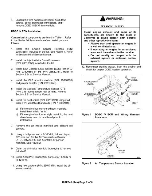
1. <strong>Install</strong> the Engine Sensor <strong>Harness</strong> (P/N:<br />
23513558), included in the kit. See Figure 1. Refer<br />
<strong>to</strong> Section 8.6 of Service Manual.<br />
2. <strong>Install</strong> the Injec<strong>to</strong>r/Jake Brake® harness<br />
(P/N: 23518358) included in the kit.<br />
3. <strong>Install</strong> new Coolant Level Sensor (CLS) (either ¼”<br />
P/N: 23520380 or 3/8” P/N; 23520381). Refer <strong>to</strong><br />
Section 2.34 of Service Manual.<br />
PERSONAL INJURY<br />
Diesel engine exhaust <strong>and</strong> some of its<br />
constituents are known <strong>to</strong> the State of<br />
California <strong>to</strong> cause cancer, birth defects,<br />
<strong>and</strong> other reproductive harm.<br />
• Always start <strong>and</strong> operate an engine in<br />
a well ventilated area.<br />
• If operating an engine in an enclosed<br />
area, vent the exhaust <strong>to</strong> the outside.<br />
• Do not modify or tamper with the<br />
exhaust system or emission control<br />
system.<br />
12. Reconnect starting power. Start the engine <strong>and</strong><br />
check for proper <strong>DDEC</strong> system operation.<br />
4. <strong>Install</strong> the CLS adap<strong>to</strong>r module (P/N: 23518206)<br />
<strong>and</strong> jumper adap<strong>to</strong>r (P/N: 23518359).<br />
5. <strong>Install</strong> the Coolant Temperature Sensor (CTS)<br />
(P/N: 23515251) at right rear of head. Refer <strong>to</strong><br />
Section 2.31 of Service Manual.<br />
6. <strong>Install</strong> the heat shield (P/N: 23519124) using stud<br />
bolts (P/N: 23509744) <strong>and</strong> nuts (P/N: 11506101).<br />
a) If the engine has current exhaust manifold,<br />
install heat shield “as is.”<br />
b) If the engine has former style manifold, the heat<br />
shield may need <strong>to</strong> be altered prior <strong>to</strong><br />
installation.<br />
7. Remove the air intake manifold <strong>and</strong> discard old<br />
gaskets.<br />
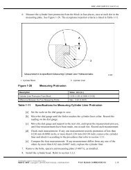
8. Using a drill press <strong>and</strong> a 9/16” drill, drill <strong>and</strong> tap a<br />
3/8” pipe port for the Air Temperature Sensor<br />
(ATS), between #3 <strong>and</strong> #4 intake air ports in<br />
manifold. See Figure 2.<br />
9. Clean the air intake manifold thoroughly <strong>to</strong> remove<br />
drill chaff.<br />
10. <strong>Install</strong> ATS (P/N: 23515250). Torque <strong>to</strong> 11-16 N·m<br />
(8-12 lb·ft).<br />
11. Using new gaskets (P/N: 23517875), install the air<br />
intake manifold.<br />
Figure 1<br />
Figure 2<br />
<strong>DDEC</strong> <strong>IV</strong> ECM <strong>and</strong> Wiring <strong>Harness</strong><br />
Locations<br />
Air Temperature Sensor Location<br />
18SP546 (Rev) Page 2 of 8