BaseStation 3200 User Manual â 11.7.5.15 ... - Baseline Systems
BaseStation 3200 User Manual â 11.7.5.15 ... - Baseline Systems
BaseStation 3200 User Manual â 11.7.5.15 ... - Baseline Systems

You also want an ePaper? Increase the reach of your titles
YUMPU automatically turns print PDFs into web optimized ePapers that Google loves.
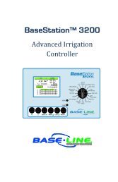
<strong>BaseStation</strong> <strong>3200</strong><br />
Advanced Irrigation<br />
Controller<br />
<strong>User</strong> <strong>Manual</strong><br />
Software Version <strong>11.7.5.15</strong><br />
April 17, 2012<br />
Contents at a Glance<br />
Section 1<br />
Section 2<br />
Section 3<br />
Section 4<br />
Section 5<br />
Section 6<br />
Section 7<br />
Section 8<br />
Section 9<br />
Section 10<br />
Section 11<br />
Section 12<br />
Introduction<br />
System Components<br />
Wiring Guidelines<br />
<strong>BaseStation</strong> <strong>3200</strong> Interface<br />
Configuring Devices<br />
Initial Programming<br />
Flow Management & Monitoring<br />
<strong>Manual</strong> Operations<br />
System Management<br />
Reports, Messages, Alerts, & Logs<br />
Troubleshooting<br />
Appendix<br />
Customer Service 1-866-294-5847
<strong>Baseline</strong> Inc.<br />
www.baselinesystems.com<br />
Phone 208-323-1634<br />
FAX 208-323-1834<br />
Toll Free 866-294-5847<br />
©2012 <strong>Baseline</strong> Inc. All Rights Reserved.<br />
Revision 2
Table of Contents<br />
1 – INTRODUCTION ................................................................................................................................ 1<br />
How to Read this <strong>Manual</strong> ................................................................................................................................ 1<br />
How to Irrigate Efficiently ............................................................................................................................... 1<br />
Soil Moisture Content ..................................................................................................................................... 2<br />
How to Use Soil Moisture Sensors Successfully ............................................................................................... 3<br />
Choosing the Primary Zone for a Scheduling Group ......................................................................................... 4<br />
Choosing the Sensor Location........................................................................................................................... 5<br />
Dealing with Slopes and Berms .................................................................................................................... 5<br />
Optimal biSensor Placement for Slopes and Berms ..................................................................................... 5<br />
Burying the biSensor ......................................................................................................................................... 5<br />
Turf Grass ..................................................................................................................................................... 6<br />
Newly Seeded Turf Grass or New Sod .......................................................................................................... 6<br />
Trees and Shrubs .......................................................................................................................................... 6<br />
Installing biSensors with New Trees ............................................................................................................. 7<br />
Shrubs and Other Ornamental Plants ........................................................................................................... 7<br />
Gardens and Crop Plants .............................................................................................................................. 7<br />
Watering Strategies ........................................................................................................................................ 7<br />
Root Depth and Plant Water Efficiency ........................................................................................................... 8<br />
Understanding Soak Cycling ............................................................................................................................ 9<br />
Precipitation Rates vs. Infiltration Rates........................................................................................................... 9<br />
Precipitation Rates for Common Sprinkler Types ......................................................................................... 9<br />
Estimated Infiltration Rates for Common Soil Types .................................................................................... 9<br />
Distribution Uniformity ................................................................................................................................. 10<br />
2 – SYSTEM COMPONENTS ............................................................................................................... 11<br />
Cabinet Options ............................................................................................................................................ 11<br />
Remote Communications Options ................................................................................................................ 11<br />
BaseManager .................................................................................................................................................. 11<br />
BL Commander ............................................................................................................................................... 12<br />
Two-Wire Devices ......................................................................................................................................... 12<br />
Total Supported Devices and Limits ............................................................................................................... 13<br />
Maximum Concurrent Valves ..................................................................................................................... 14<br />
Maximum Wire Distances for <strong>3200</strong>R and 5200R Series biCoders .............................................................. 14<br />
Installing the <strong>BaseStation</strong> <strong>3200</strong> Enclosure ..................................................................................................... 14<br />
C-series Wall Mount Cabinets......................................................................................................................... 14<br />
Connecting Power and Ground .................................................................................................................. 15<br />
X/XS-series Wall Mount Cabinets ................................................................................................................... 15<br />
Connecting Power and Ground .................................................................................................................. 16<br />
Remote Connection Modules and Antennas .............................................................................................. 16<br />
P-series Pedestal Cabinets .............................................................................................................................. 16<br />
Mounting the Pedestal to a Concrete Platform ......................................................................................... 16<br />
Remote Connection Modules and Antennas .............................................................................................. 17<br />
3 – WIRING GUIDELINES ................................................................................................................... 18<br />
Conventional Irrigation Wiring Installation ................................................................................................... 18<br />
Conventional Wiring Modules ........................................................................................................................ 18<br />
Connecting Valve Wires and Moisture Sensors over Valve Wires .................................................................. 19<br />
BL-5200 Series Powered biCoder Wiring Example with One biSensor ....................................................... 19<br />
Expanding with Two-Wire ............................................................................................................................... 20<br />
Connecting to BL-5200R Series Wall Mount biCoders .................................................................................... 21<br />
Example Wiring Diagram ............................................................................................................................ 21<br />
Page i
Two-Wire Installation ................................................................................................................................... 21<br />
Two-Wire Serial Numbers ............................................................................................................................... 22<br />
Two-Wire Connections and Layout ................................................................................................................. 22<br />
Wire Connections ....................................................................................................................................... 22<br />
Wire Lengths ............................................................................................................................................... 22<br />
Wire Layout ................................................................................................................................................ 23<br />
Wire Burial .................................................................................................................................................. 23<br />
Installing Two-Wire Devices .......................................................................................................................... 24<br />
Wiring a Valve biCoder ................................................................................................................................... 24<br />
Wiring Surge Protection and Lightning Arrestors ........................................................................................... 25<br />
Installation Instructions .............................................................................................................................. 25<br />
Wiring a Soil Moisture Sensor (biSensor) ..................................................................................................... 26<br />
Wiring a Temperature Sensor (biSensor) ..................................................................................................... 26<br />
Wiring a Pump Start Relay .............................................................................................................................. 27<br />
Wiring a Flow Device ...................................................................................................................................... 27<br />
Wiring a Flow Device +NOMV ......................................................................................................................... 28<br />
Wiring a Water Meter ..................................................................................................................................... 29<br />
Pause Devices ................................................................................................................................................. 30<br />
Wiring a Pause Button ................................................................................................................................ 30<br />
Wiring a Pause biCoder .............................................................................................................................. 30<br />
Wiring a Rain Switch and Other Normally Closed Sensing Devices ................................................................ 31<br />
Connecting a Rain Switch to the <strong>BaseStation</strong> <strong>3200</strong> .................................................................................... 31<br />
Pause Behavior for the Different Connections ........................................................................................... 31<br />
Watering Behavior for the Different Ports ................................................................................................. 31<br />
Wireless Rain Sensors ..................................................................................................................................... 32<br />
Removing a Two-Wire Device ....................................................................................................................... 32<br />
4 –BASESTATION <strong>3200</strong> INTERFACE .............................................................................................. 33<br />
Controller Front Panel Layout ....................................................................................................................... 33<br />
On-Screen Help ............................................................................................................................................. 34<br />
Auto Run Main Screen .................................................................................................................................. 34<br />
Status Colors ................................................................................................................................................. 35<br />
On-Screen Reports ........................................................................................................................................ 35<br />
5 – CONFIGURING DEVICES .............................................................................................................. 36<br />
Searching for Devices .................................................................................................................................... 36<br />
Searching for biCoders (including Powered biCoders) ................................................................................... 36<br />
Searching for biSensors .................................................................................................................................. 37<br />
Searching for Flow biCoders (including those associated with a Master Valve) ............................................ 37<br />
Searching for Pause biCoders and Temperature Sensors ............................................................................... 37<br />
Assigning Valve biCoders to Zone Numbers .................................................................................................. 38<br />
Zone Numbers are Pre-Assigned in R-Series ................................................................................................... 38<br />
Assigning biCoders to Zones ........................................................................................................................... 38<br />
Clearing a Previous Zone Number Assignment ............................................................................................... 38<br />
Understanding Zone Statuses ......................................................................................................................... 39<br />
Adjusting the Valve Power Level for a biCoder.............................................................................................. 39<br />
Configuring Other Devices ............................................................................................................................ 40<br />
Assigning Soil Moisture Sensors (biSensors) to Primary Zones ...................................................................... 40<br />
Configuring Pause Devices .............................................................................................................................. 40<br />
Configuring Flow biCoders, Flow Meters, and Flow Sensors .......................................................................... 41<br />
Configuring a Master Valve/Pump Start biCoder ........................................................................................... 41<br />
Associating a Master Valve/Pump Start biCoder with Programs ................................................................... 41<br />
Page ii
6 – INITIAL PROGRAMMING ............................................................................................................. 42<br />
Power Cycling or Restarting the Controller ................................................................................................... 42<br />
Setting the Controller Date and Time ............................................................................................................ 42<br />
Checking the Software Version on Your Controller ....................................................................................... 42<br />
Setting Up Time-Based Watering .................................................................................................................. 43<br />
Setting Up a Timed Zone ................................................................................................................................. 43<br />
To set up a timed zone ............................................................................................................................... 43<br />
Modifying the Default Settings for a Zone ...................................................................................................... 43<br />
To modify the default settings for a zone .................................................................................................. 44<br />
Assigning a Primary Zone ................................................................................................................................ 44<br />
Prerequisites ............................................................................................................................................... 44<br />
To assign a primary zone ............................................................................................................................ 45<br />
Linking Zones (Creating a Scheduling Group) ................................................................................................. 45<br />
Adjusting the Water Time Tracking Ratio of Linked Zones ............................................................................. 45<br />
Using Soak Cycles .......................................................................................................................................... 46<br />
To enable the default soak-cycle settings ....................................................................................................... 46<br />
To change soak-cycle settings for timed zones .............................................................................................. 47<br />
To disable soak cycles ..................................................................................................................................... 47<br />
Setting Up Programs ..................................................................................................................................... 47<br />
To set up the start times for a program .......................................................................................................... 48<br />
To set up the water windows for a program .................................................................................................. 48<br />
To set up the day intervals for a program ...................................................................................................... 49<br />
To set up historical ET-based watering for a program .................................................................................... 49<br />
Prerequisites ............................................................................................................................................... 49<br />
Instructions ................................................................................................................................................. 50<br />
To adjust the water budget for programs ...................................................................................................... 50<br />
Associating Zones with a Program ................................................................................................................ 51<br />
Setting Up Soil Moisture Sensor Based Watering .......................................................................................... 51<br />
Prerequisites for Watering with Soil Moisture Sensors .................................................................................. 52<br />
To configure your biSensors and set up watering strategies .......................................................................... 52<br />
Understanding Upper and Lower Limit Watering Strategies ......................................................................... 53<br />
Lower Limit ..................................................................................................................................................... 53<br />
<strong>Manual</strong>........................................................................................................................................................ 53<br />
Auto ............................................................................................................................................................ 53<br />
Upper Limit ..................................................................................................................................................... 54<br />
<strong>Manual</strong>........................................................................................................................................................ 54<br />
Auto ............................................................................................................................................................ 54<br />
Complying with Water Restrictions ............................................................................................................... 55<br />
Setting Up Event Days ................................................................................................................................... 56<br />
To add a new event day .................................................................................................................................. 56<br />
To edit existing event days ............................................................................................................................. 56<br />
To remove an event day ................................................................................................................................. 56<br />
7 – FLOW MANAGEMENT & MONITORING .................................................................................. 57<br />
Configuring a Flow Device ............................................................................................................................. 57<br />
Flow Device Limits and Monthly Budget ........................................................................................................ 58<br />
To configure the flow device limits ............................................................................................................ 59<br />
Mainline Setup ................................................................................................................................................ 59<br />
To set up the mainline ................................................................................................................................ 61<br />
Managing Concurrent Zones........................................................................................................................... 61<br />
Example ...................................................................................................................................................... 62<br />
To manage concurrent zones by controller and program .......................................................................... 62<br />
Learning Flow .................................................................................................................................................. 62<br />
Page iii
Learning the Flow by Program .................................................................................................................... 62<br />
Learning the Flow by Zone ......................................................................................................................... 63<br />
Multiple Flow Devices and Mainlines ............................................................................................................ 64<br />
To assign mainline numbers to your flow devices and programs................................................................... 64<br />
8 – MANUAL OPERATIONS ................................................................................................................ 65<br />
<strong>Manual</strong>ly Running a Program ........................................................................................................................ 65<br />
Forcing a Program to Start .............................................................................................................................. 65<br />
Stopping an Active Program ........................................................................................................................... 65<br />
Setting the Next Start Date for a Program ...................................................................................................... 66<br />
Watering <strong>Manual</strong>ly ....................................................................................................................................... 66<br />
<strong>Manual</strong>ly Running One Zone .......................................................................................................................... 66<br />
<strong>Manual</strong>ly Running All Zones ........................................................................................................................... 67<br />
<strong>Manual</strong>ly Running the Zones of a Program .................................................................................................... 68<br />
Setting Up a Rain Delay ................................................................................................................................. 69<br />
To set up a rain delay ...................................................................................................................................... 69<br />
To clear a rain delay ........................................................................................................................................ 69<br />
Setting the System to OFF ............................................................................................................................. 69<br />
9 – SYSTEM MANAGEMENT .............................................................................................................. 70<br />
Setting Up a Passcode ................................................................................................................................... 70<br />
Changing the Serial Number of Your Controller ............................................................................................ 70<br />
Using the USB Data Functions ....................................................................................................................... 71<br />
Backing Up Your System ................................................................................................................................. 71<br />
Restoring Your System .................................................................................................................................... 71<br />
Exporting Log Files .......................................................................................................................................... 72<br />
Importing Log Files .......................................................................................................................................... 72<br />
Updating the Controller Software ................................................................................................................. 73<br />
To download the software from the <strong>Baseline</strong> web site .................................................................................. 73<br />
To unzip the compressed update file ............................................................................................................. 73<br />
To copy the Update folder to your USB drive ................................................................................................. 73<br />
To update the software on the controller ...................................................................................................... 74<br />
Using the Clear All Option ............................................................................................................................. 74<br />
10 – REPORTS, MESSAGES, ALERTS, & LOGS .............................................................................. 75<br />
Zone Status ................................................................................................................................................... 75<br />
Program Status ............................................................................................................................................. 76<br />
To display the Program Status report ............................................................................................................. 76<br />
Moisture Sensor Data ................................................................................................................................... 77<br />
To display the Soil Moisture Sensor Data report ............................................................................................ 77<br />
Water Used ................................................................................................................................................... 77<br />
To display the Water Used reports ................................................................................................................. 77<br />
Pause Conditions .......................................................................................................................................... 78<br />
To display the Pause Conditions report .......................................................................................................... 79<br />
Operator Messages ....................................................................................................................................... 79<br />
To display the Messages ................................................................................................................................. 79<br />
Viewing Exported Log Files ........................................................................................................................... 80<br />
Saving Exported Log Files to a Computer ...................................................................................................... 80<br />
11 – TROUBLESHOOTING ................................................................................................................. 82<br />
Testing Zones, Valves, and biCoders ............................................................................................................. 82<br />
Testing Soil Moisture Sensors (biSensors) ..................................................................................................... 83<br />
Testing All Devices ........................................................................................................................................ 84<br />
Repairing Device Assignments and Addresses ............................................................................................... 85<br />
Page iv
Troubleshooting the Two-Wire: High Current or Shorted .............................................................................. 85<br />
Troubleshooting: Lost Devices | No Response .............................................................................................. 86<br />
12 – APPENDIX ..................................................................................................................................... 87<br />
Warranty ...................................................................................................................................................... 87<br />
BL-<strong>3200</strong>-R Hydrozone Worksheet ................................................................................................................. 88<br />
Existing Irrigation Controller Information ....................................................................................................... 88<br />
Additional Information for Existing Programs ................................................................................................ 89<br />
Programming Information for the <strong>BaseStation</strong> <strong>3200</strong> Controller .................................................................... 89<br />
Additional Information for New Programs ..................................................................................................... 90<br />
Glossary of Terms ......................................................................................................................................... 91<br />
Page v
Page vi
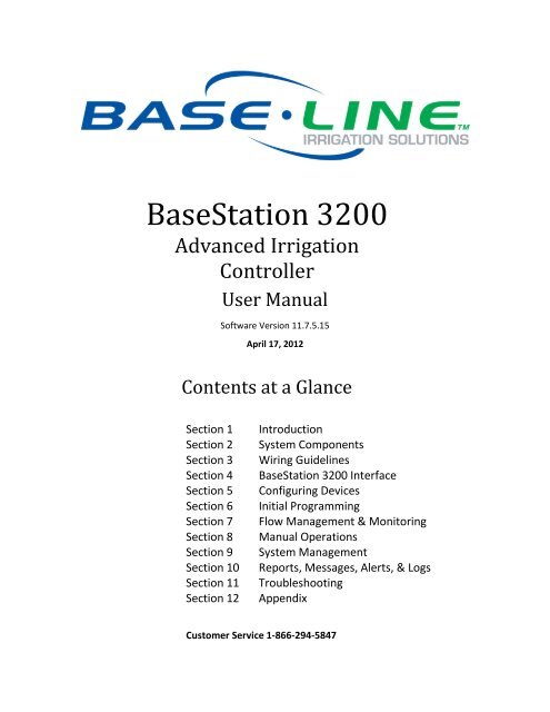
<strong>BaseStation</strong> <strong>3200</strong> Advanced Irrigation Controller <strong>Manual</strong><br />
1 – INTRODUCTION<br />
Congratulations on choosing the most capable and easiest to use commercial grade smart irrigation controller in<br />
the world! You will find that the <strong>BaseStation</strong> <strong>3200</strong> is capable of dramatically reducing your water use while<br />
improving the health and quality of your landscape. Fully central control compatible, the <strong>BaseStation</strong> <strong>3200</strong><br />
controller will typically pay for itself in one to two seasons based on water waste reduction alone.<br />
The <strong>BaseStation</strong> <strong>3200</strong> is specifically designed to help you irrigate more efficiently than any other commercial<br />
irrigation controller. The <strong>3200</strong> supports multiple smart watering strategies, including Historical ET, and smart<br />
watering with soil moisture sensors.<br />
At <strong>Baseline</strong>, our mission is to forever change the way people water plants by providing the smartest, easiest and<br />
most capable irrigation control products ever made. If you have feedback on how we can make our products<br />
better, please do not hesitate to contact us.<br />
IMPORTANT NOTE! Install all electrical components including the <strong>BaseStation</strong> controller in compliance with local<br />
electrical and building codes.<br />
How to Read this <strong>Manual</strong><br />
For first time users, sections 1 through 6 provide an overview of how to get your new <strong>BaseStation</strong> <strong>3200</strong> controller<br />
up and running quickly, while sections 7 through 10 provide information on advanced functions and<br />
troubleshooting.<br />
For additional information, you can also visit the <strong>Baseline</strong> web site at http://www.baselinesystems.com<br />
To get the most out of your <strong>BaseStation</strong> <strong>3200</strong>, we recommend that you review the information in this Introduction<br />
before you install and configure your system.<br />
How to Irrigate Efficiently<br />
This section covers some key concepts that are essential to better and more efficient irrigation. When you irrigate<br />
properly, you will reduce or eliminate water waste and improve the health of your plants.<br />
All other considerations being equal, you will see better watering results with soil moisture sensors than with any<br />
other currently available technology. When you set up your <strong>BaseStation</strong> <strong>3200</strong> to water based on soil moisture<br />
sensor data, your system becomes a “closed loop” – in other words, the soil moisture sensor directly measures the<br />
moisture in the root zone, and the controller adjusts to maintain the desired moisture levels.<br />
• Water deeply and infrequently. Studies show that watering deeply and infrequently promotes deeper root<br />
growth and more drought tolerant plants.<br />
Watering deeply means that the soil should be wetted down to a depth of 6 inches or deeper for grasses and<br />
12 inches or deeper for trees and shrubs.<br />
Watering infrequently means that the next irrigation event (or start time) should be delayed as long as<br />
possible without stressing the plants.<br />
• Deeper roots = more efficient plants. Plants with deeper roots are able to draw more nutrients from a larger<br />
area of soil, making fertilizers and soil treatments more effective.<br />
Page 1
<strong>BaseStation</strong> <strong>3200</strong> Advanced Irrigation Controller <strong>Manual</strong><br />
• Avoid runoff. Matching the application rate of irrigation to the infiltration rate of the soil is critical to avoid<br />
runoff.<br />
• Only apply the amount of water needed. Irrigation water is a supplement to natural rainfall – you only need<br />
to apply the amount of water needed to return the soil to optimum moisture.<br />
Irrigation water applied above the field capacity of the soil is wasted – water will gravitationally sink through<br />
the soil below the root zone of the plants.<br />
Unlike other irrigation controllers, the <strong>3200</strong> is specifically designed to make efficient irrigation easy. Before you<br />
start setting up and programming your <strong>BaseStation</strong> <strong>3200</strong>, it is helpful to understand the following concepts:<br />
• Soil Moisture Content<br />
• How to Use Soil Moisture Sensors, including:<br />
• Hydrozones, scheduling groups, and primary zones<br />
• Watering Strategies<br />
• Root Depth and Plant Water Efficiency<br />
• Soak Cycling<br />
• Distribution Uniformity<br />
The remainder of this section covers these key concepts in more detail.<br />
Soil Moisture Content<br />
Soil scientists and agronomists have been studying the plant-water-soil system for over 100 years. Early work in<br />
irrigation efficiency focused on the estimation of soil moisture based on weather information, plant water<br />
requirements, and soil information such as soil texture and slope. With the availability of inexpensive and highly<br />
accurate soil moisture sensors, we are able to take soil moisture based irrigation to a whole new level of efficiency<br />
and effectiveness.<br />
With soil moisture sensors, your controller can operate like a thermostat for your landscape – applying water<br />
when it is needed, and where it is needed.<br />
Page 2
<strong>BaseStation</strong> <strong>3200</strong> Advanced Irrigation Controller <strong>Manual</strong><br />
To understand soil moisture based smart irrigation, you also need to understand the following industry standard<br />
terms for soil moisture content.<br />
Drier Wetter<br />
Saturation<br />
Field Capacity<br />
Maximum<br />
Allowed<br />
Depletion (MAD)<br />
Permanent Wilt<br />
Point<br />
Oven Dry<br />
The soil pores are filled with water and nearly all of the air in the soil has been<br />
displaced by water. Gravity exerts force on the water contained in saturated<br />
soils, moving it deeper into the ground (if possible). When this “gravitational<br />
water” moves down through the soil, it becomes unavailable to plants.<br />
The level of soil moisture left in the soil after drainage of the gravitational<br />
water. If you irrigate to a level above field capacity, it will result in runoff or<br />
drainage as gravitational water.<br />
When the soil moisture content reaches this level, irrigation needs to start. In<br />
most cases, the maximum allowed depletion level is well before the plants<br />
begin to show visible signs of stress. Irrigators typically start watering at or<br />
before MAD is reached because they do not want their landscapes to show signs<br />
of stress.<br />
The minimal point of soil moisture where the plants wilt and begin to die off.<br />
When soil is dried in an oven, nearly all water is removed. This moisture content<br />
is used to provide a reference for measuring saturation, field capacity, and<br />
MAD.<br />
One key point is that water applied above field capacity is generally wasted – it gravitationally moves down<br />
through the soil and becomes unavailable to plants. Excess water will also leech nutrients from the soil into deeper<br />
soil layers, reducing the efficiency of fertilizers and soil treatments.<br />
To understand field capacity, it is often useful to think of a sponge. If you dunk a sponge in a bucket of water and<br />
pull it out, water will gravimetrically drain from the sponge for a period of time. When the dripping stops, the<br />
sponge will still be very wet. This moisture level is roughly equivalent to field capacity in soils – water is no longer<br />
draining into lower soil layers and is held in the root zone of the plants.<br />
When your irrigation system maintains soil moisture content between field capacity and maximum allowed<br />
depletion, you will find that your plants are healthier and your water use actually decreases. Studies also show that<br />
appropriately varying the time between irrigation events in order to allow the soil to dry to the chosen depletion<br />
point promotes deeper root growth and subsequently more efficiency and drought tolerance from the plants.<br />
How to Use Soil Moisture Sensors Successfully<br />
The first key for success with soil moisture sensors is to consider the hydrozones that exist in your landscaping. A<br />
hydrozone is a grouping of plants that have similar water usage and delivery characteristics and can be watered<br />
the same. For example, each of the following landscaping areas is a separate hydrozone:<br />
• Grass in full sun with rotors<br />
• Grass in full sun with sprays<br />
• Drip zones in full sun<br />
• Grass in shade with rotors<br />
• Grass in shade with sprays<br />
• Drip zones in shade<br />
Page 3
<strong>BaseStation</strong> <strong>3200</strong> Advanced Irrigation Controller <strong>Manual</strong><br />
After you have identified the hydrozones in your landscaping, determine which irrigation zones are used to water<br />
those hydrozones, and then put the irrigation zones into scheduling groups based on their common characteristics.<br />
Within the scheduling group, designate the zone where the sensor is located to be the “primary” zone, and then<br />
you set up the watering strategy for the scheduling group based on the readings from that sensor. You can link the<br />
other zones in the scheduling group to the primary zone so they will be watered more or less relative to it. These<br />
zones are called “linked” zones. For more information, refer to Linking Zones (Creating a Scheduling Group) on<br />
page 45.<br />
A scheduling group can include any zones that:<br />
• Require irrigation on the same frequency (for example, on the same days)<br />
• Have similar plant types (such as turf, shrubs, or flowers)<br />
• Do not have excessive differences in sun or wind exposure<br />
• Are irrigated with similar water application technologies (assuming zones meet the criteria above)<br />
You can group spray, rotor, and multi-stream zones, as long as the difference in application rates is less than 10x.<br />
You can also put drip zones into one group, and subsurface drip zones into another group.<br />
Consider the following example of a sports park that has four baseball fields and four soccer fields in addition to<br />
some perimeter and parking lot shrub areas.<br />
The irrigation manager for the park wants to water the infield areas of the baseball fields differently from the<br />
outfields. The manager puts the zones that water the infields of all four baseball diamonds into one scheduling<br />
group that is controlled by a single soil moisture sensor in one of the infields.<br />
Likewise, the manager puts all zones covering the outfields into a second scheduling group controlled by a single<br />
moisture sensor in one of the outfields.<br />
Because all the soccer fields have similar plant types and sun exposures, the irrigation manager can group all zones<br />
for all the soccer fields together and control them with a single soil moisture sensor located in one of the fields.<br />
Lastly, the irrigation manager breaks the parking lot and perimeter shrub beds into two scheduling groups<br />
representing sunny and shady exposures.<br />
In this way, the irrigation manager is able to configure 42 individual zones into 5 scheduling groups that are<br />
controlled by 5 soil moisture sensors.<br />
In the example above, the irrigation manager would configure the 5 scheduling groups for the Upper Limit or<br />
Lower Limit watering strategy based on readings from the associated soil moisture sensors. However, each<br />
scheduling group can be watered according to any watering strategy appropriate for that section of the landscape.<br />
Choosing the Primary Zone for a Scheduling Group<br />
Because the zones in a scheduling group are naturally similar, any zone in a group can make a good primary zone<br />
(the zone where the sensor is located). For large scheduling groups, or scheduling groups with a higher level of<br />
variation in sun or wind exposure, choose a primary zone that:<br />
• Requires irrigation the most frequently<br />
• Has an average or greater sun and wind exposure for the scheduling group<br />
IMPORTANT NOTE! The primary zone must be configured in the <strong>BaseStation</strong> <strong>3200</strong> system at an address with a<br />
lower number than the other zones within the same scheduling group. For example, if zones 1 – 50 are in one<br />
scheduling group, zone 1 would be the primary zone. For retrofits, you may need to renumber your zones in order<br />
to meet this requirement.<br />
Page 4
<strong>BaseStation</strong> <strong>3200</strong> Advanced Irrigation Controller <strong>Manual</strong><br />
Choosing the Sensor Location<br />
You will achieve the best results by locating the biSensor in an area that is average for the zone and ideally for the<br />
entire scheduling group. Avoid the following areas:<br />
• Drainage areas where irrigation or rainwater pools or is channeled<br />
• Areas immediately around hardscapes or that receive runoff water from hardscapes or buildings<br />
As long as the location of the sensor is average for the zone, you should achieve excellent water efficiency.<br />
Dealing with Slopes and Berms<br />
Steep slopes and berms are possibly the most difficult landscape areas to irrigate efficiently. The main issue is<br />
runoff, but often subsurface drainage issues result in low areas that get soaking wet and high areas that are bone<br />
dry. When a berm is constructed, the central mass is typically compacted, which can also cause water movement<br />
and drainage issues.<br />
Soil moisture sensors are an excellent tool to optimize watering for slopes and berms because the sensor can<br />
detect how much irrigation water is actually infiltrating the upper levels of the slope or berm.<br />
Take care when you set the soak and cycle times for slopes and berms – for some slopes, you might need to break<br />
the total run time into five or more cycles.<br />
Optimal biSensor Placement for Slopes and Berms<br />
If the slope or berm is irrigated as a part of a larger zone that is mostly level, <strong>Baseline</strong> recommends that you place<br />
the sensor in the larger level area. However, for most efficient results, set up separate zones to water the top,<br />
middle, and bottom of slopes and berms.<br />
Burying the biSensor<br />
Install the biSensor according to the installation instructions that are included with it. When installing a biSensor in<br />
an established landscape, avoid disturbing the surrounding soil in order to reduce the chance that adjustments will<br />
be needed later.<br />
In general, you should install the biSensors in the top 1/3 of the root zone for the plant that is being irrigated. In<br />
the case of turf grass, the top of the sensor blade should be 2 inches to 3 inches from the bottom of the thatch<br />
layer.<br />
Note: Burying the moisture sensor too deep can cause poor results. If the sensor is deeper than the top 1/3 of the<br />
root zone, these roots can become too dry and the plants may become stressed.<br />
Page 5
<strong>BaseStation</strong> <strong>3200</strong> Advanced Irrigation Controller <strong>Manual</strong><br />
Turf Grass<br />
As previously stated, you should bury the sensor 2 inches to 3 inches below the thatch layer, or in the top 1/3 of<br />
the root zone of the grass.<br />
Newly Seeded Turf Grass or New Sod<br />
The default watering strategies for the <strong>3200</strong> are intended to optimize water efficiency for established plants and<br />
turf. This style of watering can result in poor performance for newly seeded turf.<br />
If you want to install a sensor in newly seeded turf grass, follow the installation instructions and bury the sensor at<br />
the proper depth. <strong>Baseline</strong> recommends that you water according to an appropriate timed schedule until the grass<br />
has rooted sufficiently (typically 60 to 90 days) before enabling a sensor based watering strategy. After the grass<br />
has rooted, you can convert the primary zone to a sensor based watering strategy.<br />
Likewise, newly installed sod has very shallow roots. Water the new sod on an appropriate time schedule until it<br />
has rooted sufficiently to enable a sensor based watering strategy (typically 30 to 60 days).<br />
Trees and Shrubs<br />
If trees and shrubs are watered separately, a moisture sensor is an excellent tool to maintain their health and<br />
beauty. Typically, multiple trees are watered by the same zone. If so, choose an average tree, and install the<br />
biSensor in the top 1/3 of the root zone of the tree.<br />
biSensor in the top 1/3 of the root zone of an established tree<br />
Angling the sensor can monitor a deeper soil profile for trees that have deep root structures.<br />
If the tree is watered with drip emitters or bubblers, install the sensor in a location that is not directly under the<br />
emitter or bubbler to avoid partial watering of the whole root zone of the tree. If multiple emitters are used for a<br />
single tree, a good rule of thumb is to install the sensor roughly half way between two emitters and as much inside<br />
the root mass of the tree as possible without damaging the roots.<br />
Page 6
<strong>BaseStation</strong> <strong>3200</strong> Advanced Irrigation Controller <strong>Manual</strong><br />
Note: Root depth and water requirements for trees and shrubs vary much more greatly than for turf. Consult an<br />
experienced Arborist or Master Gardener for specific guidelines for watering trees.<br />
Most trees are watered along with turf in commercial landscapes. In this case, <strong>Baseline</strong> recommends that you<br />
install biSensors in the turf areas and that you adjust the default run times of zones with trees to ensure water<br />
application to 12 inches or whatever is required to optimize tree health.<br />
Installing biSensors with New Trees<br />
In the case of new landscape with newly installed trees that are watered separately from turf zones, it is important<br />
to make sure that the sensor is located as close to the root ball in the top 1/3 of the root ball as possible. Watering<br />
new trees with a sensor based watering strategy is a good way to avoid inadvertently “drowning” new trees and<br />
shrubs due to overwatering.<br />
Shrubs and Other Ornamental Plants<br />
Many landscapes feature shrub zones that are separately watered from turf zones. Shrubs generally have very<br />
different water needs from turf, so having separate zones is a good thing!<br />
For shrub zones, choose a representative plant, and then install the in or close to the top 1/3 of the root zone for<br />
the plant, without damaging the root structure of the plant.<br />
If drip emitters or bubblers are used, install the sensor in a location that is not directly under the emitter or<br />
bubbler to avoid partial watering of the whole root zone of the plant.<br />
Gardens and Crop Plants<br />
Sensors are excellent tools for maximizing crop results. They have been used for decades in irrigated agriculture.<br />
Garden and crop plant watering depends greatly on the type of plants being grown, and a discussion of this topic is<br />
beyond the scope of this manual.<br />
To plan a watering strategy for larger gardens or crops, <strong>Baseline</strong> recommends that you contact your local<br />
Cooperative Extension Office. You can find a national register of the extension offices at:<br />
http://www.csrees.usda.gov/Extension/<br />
Watering Strategies<br />
Each property is unique and has unique watering requirements. In order to support a broad range of climate<br />
zones, plant types, landscape designs, and landscape usage requirements, the <strong>BaseStation</strong> <strong>3200</strong> provides a variety<br />
of watering strategies.<br />
The basic watering strategies supported by the <strong>3200</strong> are shown in the following table.<br />
Timed<br />
Historical<br />
ET<br />
Lower Limit<br />
Like all irrigation controllers, you can program the <strong>3200</strong> to run zones on specific times and dates.<br />
Timed irrigation is the default setting for any zone that has not been associated with a moisture<br />
sensor. Refer to Setting Up a Timed Zone on page 43.<br />
The <strong>BaseStation</strong> <strong>3200</strong> allows you to set the days between irrigation according to a Historical ET<br />
calendar. This watering strategy, unlike typical seasonal adjustments, will promote deeper root<br />
growth and healthier plants throughout the season. However, Historical ET based watering will<br />
not protect your landscape from unusual weather patterns in any given season. Read the topic<br />
To set up historical ET-based watering for a program on page 49.<br />
Also called Lower Threshold. In this soil moisture based, smart watering strategy, irrigation is<br />
suspended or skipped until the soil dries to the lower limit, which may be set manually, or set<br />
using the automatic calibration process. This watering strategy naturally waters deeply and<br />
Page 7
<strong>BaseStation</strong> <strong>3200</strong> Advanced Irrigation Controller <strong>Manual</strong><br />
infrequently and promotes deeper root growth in plants. The controller will water for a specified<br />
run time each time it is allowed to water. When you are using this watering strategy, remember<br />
to ensure that ½ inch or more of water is applied frequently enough to water sufficiently during<br />
the hottest period of the season. Refer to Understanding Upper and Lower Limit Watering<br />
Strategies on page 53.<br />
Lower Limit<br />
Automatic<br />
Upper<br />
Limit<br />
Upper<br />
Limit<br />
Automatic<br />
Lower Limit Automatic waters according to a lower limit strategy, but automatically performs a<br />
calibration cycle each month in order to measure actual soil field capacity. This strategy is<br />
particularly useful for newly established landscapes where compaction and organic development<br />
of soil can cause field capacity to vary significantly over time. Refer to Understanding Upper and<br />
Lower Limit Watering Strategies on page 53.<br />
Also called Upper Threshold. In this soil moisture based, smart watering strategy, irrigation<br />
events are scheduled for specific times and dates, but the total run time is adjusted by the<br />
controller to bring soil moisture up and very slightly over field capacity. This watering strategy is<br />
particularly useful for landscapes that need to be at a desired moisture level on a regular<br />
schedule, such as sports fields or heavy use parks. On these types of properties, damage to turf<br />
takes place when the soil is either too wet or too dry. Refer to Understanding Upper and Lower<br />
Limit Watering Strategies on page 53.<br />
Upper Limit Automatic waters according to an upper limit strategy, but automatically performs a<br />
calibration cycle each month in order to measure actual soil field capacity. This strategy is<br />
particularly useful for newly established landscapes where compaction and organic development<br />
of soil can cause field capacity to vary significantly over time. Refer to Understanding Upper and<br />
Lower Limit Watering Strategies on page 53.<br />
One important thing to remember about watering strategies – any one zone (or valve) can only be watered<br />
according to one strategy. In other words, you cannot configure a zone to be watered automatically using a soil<br />
moisture sensor and also be watered on a separate timed schedule.<br />
Zones can be linked together and watered as a group, regardless of the watering strategy selected. Refer to Linking<br />
Zones (Creating a Scheduling Group) on page 45 for more information.<br />
Also note that, even with soil moisture based watering strategies, it is important to program the controller so it will<br />
put down as much water as required to maintain plant health during the heat of the summer. The <strong>3200</strong> has built-in<br />
limits that control how much it is allowed to modify run times or watering days before it assumes that there is an<br />
equipment malfunction of some kind.<br />
One of the most common irrigation programming mistakes is to apply too little water during the hottest days of<br />
the season. <strong>Baseline</strong> recommends that, regardless of watering strategy, you program each zone to water long<br />
enough to put down at least ½ inch of water each time the controller is allowed to water.<br />
Root Depth and Plant Water Efficiency<br />
Studies show that most plants, in particular standard turf grasses, do not grow deeper roots unless prompted to do<br />
so. While some turf grass varietals rapidly grow deeper root structures when properly watered, even Kentucky<br />
bluegrass will grow roots in excess of 12 inches in appropriate soil textures when it is watered optimally.<br />
Watering deeply and infrequently on a consistent basis will promote healthier plants with deeper root structures.<br />
As roots grow deeper, the plants are then able to access water in deeper and typically wetter soil layers, making<br />
them even more water efficient. Plants with deeper roots are also able to draw nutrients and fertilizers from<br />
deeper soil layers, making the plants more nutrition efficient as well.<br />
Page 8
<strong>BaseStation</strong> <strong>3200</strong> Advanced Irrigation Controller <strong>Manual</strong><br />
Understanding Soak Cycling<br />
When you set up your irrigation programs, remember that the rate at which the irrigation application devices<br />
apply water might be very different than the rate at which the soil in your landscape can take up that water.<br />
Soak cycling breaks the total run time into shorter water “cycles” with “soak” periods in between to allow time for<br />
water to soak into the soil.<br />
Precipitation Rates vs. Infiltration Rates<br />
The precipitation rate, which is the rate at which sprinkler heads or drip emitters apply water to the soil, is typically<br />
measured in inches, like rainfall.<br />
Many soils only allow water infiltration at a rate of .25 inch per hour or less, whereas most head types put down<br />
.50 inch per hour or more (much more in the case of some spray heads).<br />
Also remember that head spacing and overlap directly influence the total precipitation rate for any specific zone.<br />
Precipitation Rates for Common Sprinkler Types<br />
Spray Heads 1.00 inch to greater than 5.00 inches per hour<br />
Gear Driven Rotors<br />
0.25 inch to 0.65 inch per hour<br />
Multi-stream Rotors 0.40 inch to 0.60 inch per hour<br />
Drip Emitters<br />
Depends on area covered, rarely exceeds infiltration rate<br />
Estimated Infiltration Rates for Common Soil Types<br />
Course Sand 0.75 inch to 1.00 inch per hour<br />
Fine Sand<br />
Find Sandy Loam<br />
Silt Loam<br />
Clay Loam<br />
0.50 inch to 0.75 inch per hour<br />
0.35 inch to 0.50 inch per hour<br />
0.15 inch to 0.40 inch per hour<br />
0.10 inch to 0.20 inch per hour<br />
As you can see from the tables above, most sprinkler heads have higher precipitation rates than the infiltration<br />
rate of most soils.<br />
When the irrigation schedule puts down more water than the soil can take up, the excess water will typically run<br />
off to the lowest point, leaving some areas of the landscape, or even the entire irrigated landscape, under<br />
watered. Standing water also evaporates at a fairly high rate, especially in the heat of the summer months, further<br />
reducing irrigation efficiency.<br />
Even on a perfectly designed system, it is important to match the water application rate to the infiltration rate of<br />
your soil. You can achieve this balance by breaking a total run time for any zone into multiple “cycles” (timed water<br />
applications) and “soaks” (timed wait periods for the water applied in the last cycle to infiltrate into the soil before<br />
applying more water).<br />
The <strong>BaseStation</strong> <strong>3200</strong> has built-in support for soak cycling and has intelligent watering algorithms that apply cycles<br />
in the optimal order to maximize water penetration and minimize evaporation loss.<br />
Note: Soak Cycling is required on all soil moisture based zones or scheduling groups in order to ensure that the<br />
applied irrigation water is reaching the moisture sensor.<br />
As a rule-of-thumb, <strong>Baseline</strong> recommends that you break the total run time for any zone into at least 3 cycles, and<br />
configure the soak time between cycles to be at least twice the length of the cycle time.<br />
Page 9
<strong>BaseStation</strong> <strong>3200</strong> Advanced Irrigation Controller <strong>Manual</strong><br />
Note: One easy way to determine good cycle times is to turn a zone on and watch for first signs of standing water<br />
or runoff. Set the cycle time to be no more than this amount of time.<br />
Properly setting soak and cycle times will dramatically improve water penetration and watering efficiency.<br />
Distribution Uniformity<br />
Distribution uniformity (DU) refers to how evenly water is applied over the area in a particular zone or landscape.<br />
This is generally driven by the choice of heads (spray, rotor, multi-stream, etc.) and by the irrigation design.<br />
In reality, it is very common that distribution uniformity is fairly low in irrigated landscapes. Poor distribution<br />
uniformity is based on many factors beyond the scope of this manual, but it is important to note that system<br />
problems such as uneven coverage will limit the effectiveness of smart watering strategies.<br />
<strong>Baseline</strong>’s experience is that high-uniformity systems can be built from nearly any head type, as long as it is<br />
properly designed, installed and maintained.<br />
IMPORTANT NOTE! The <strong>BaseStation</strong> <strong>3200</strong> controller can compensate for, but cannot solve, distribution uniformity<br />
problems.<br />
As you intelligently reduce water applied to any zone, you may notice stressed areas or brown spots in your<br />
landscape. When this happens, you should first adjust your heads to make coverage as even as possible. In<br />
extreme cases, you may find it advantageous to retrofit older heads with new types of heads such as multi-stream<br />
rotors that apply water more evenly.<br />
Note: Fixing distribution uniformity issues has better long term results than increasing run times or moisture<br />
settings.<br />
Every irrigation controller must be programmed to water to the “driest spot” in each zone. If the difference<br />
between water applied at the driest spot is too great (especially if the wettest spot has more than 3 times the<br />
water applied in the same period as to the dries spot) then you should take steps to adjust your heads, their<br />
spacing, and their coverage to gain better uniformity.<br />
You can quickly and easily measure the distribution uniformity of your landscape by placing catch cups in any<br />
particular zone and then running that zone for a specific period of time. Auditing zones in this manner will also give<br />
you precise information about how much water is applied per hour in that zone, which makes it easy to set default<br />
run times. <strong>Baseline</strong> highly recommends that you audit zones in order to determine uniformity and actual<br />
application rates.<br />
Page 10
<strong>BaseStation</strong> <strong>3200</strong> Advanced Irrigation Controller <strong>Manual</strong><br />
2 – SYSTEM COMPONENTS<br />
This section covers the components, devices, and communication options that are available for the <strong>BaseStation</strong><br />
<strong>3200</strong> irrigation controller. Review this information to learn about how many devices are supported and how to<br />
install your enclosure.<br />
Cabinet Options<br />
Your <strong>BaseStation</strong> <strong>3200</strong> will be installed in one of the following cabinets:<br />
All cabinets are constructed from 16 gauge steel.<br />
• C-series – Powder-coated indoor/outdoor wall mount cabinet<br />
• X-series – Powder-coated (X) or stainless steel (XS) indoor/outdoor large wall mount cabinet<br />
• P-series – Stainless steel pedestal cabinet<br />
C-series X/XS-series P-series<br />
All cabinet dimensions are in inches (in).<br />
Remote Communications Options<br />
The <strong>BaseStation</strong> <strong>3200</strong> is compatible with a number of remote communications options to enable remote access<br />
and central control using <strong>Baseline</strong>’s BaseManager system or BaseManager Web service.<br />
BaseManager<br />
BaseManager is central control software that is used to manage and control numerous <strong>BaseStation</strong> <strong>3200</strong><br />
controllers. The software runs on a standard Microsoft Windows based computer and communicates with the<br />
<strong>3200</strong> controllers over a variety of connection options. More information is available on the <strong>Baseline</strong> web site<br />
(http://www.baselinesystems.com).<br />
Page 11
<strong>BaseStation</strong> <strong>3200</strong> Advanced Irrigation Controller <strong>Manual</strong><br />
Communication options include the following:<br />
• Cellular Modem<br />
• Ethernet<br />
• Wireless Ethernet (Wi-Fi)<br />
• Wireless RF spread spectrum radio<br />
• Direct RS-232 connection<br />
Note: To install the remote communication devices, refer to the<br />
instructions included with the device.<br />
BL Commander<br />
The BL-Commander is a handheld radio for activating valves while away from the <strong>BaseStation</strong> <strong>3200</strong> controller. The<br />
radio receiver is powered from the BL-<strong>3200</strong>X series controller and can be easily moved between controllers for<br />
field service and repair. More information is available on the <strong>Baseline</strong> web site (http://www.baselinesystems.com).<br />
• BL Commander Handheld Remote Control<br />
You can connect a BL Commander handheld remote control unit to the <strong>BaseStation</strong> <strong>3200</strong>. The BL Commander<br />
unit is a special version of the popular TRC Commander remote control unit manufactured by Irrigation<br />
Remotes and is compatible with all TRC Commander accessories and antennas.<br />
• BL Commander Permanent Mount Receiver Kits<br />
A permanent receiver kit may be factory or field installed. It communicates digitally with the <strong>BaseStation</strong> <strong>3200</strong><br />
unit via a special internal port in the controller. With this option, you can operate your controllers using a BL<br />
Commander handheld unit. The receiver kit has DIP switches to set group and unit security codes.<br />
• BL Commander Mobile Receiver<br />
A mobile receiver unit connects to any compatible <strong>3200</strong> controller through the remote control port on the<br />
front panel. The mobile receiver unit receives power from the controller.<br />
• BL Commander Universal Receiver Adapter<br />
You can use a Universal Receiver Adapter unit to operate older conventionally wired controllers with the BL<br />
Commander handheld remote control unit. You can operate up to 32 stations with the Universal Receiver<br />
Adapter. To turn zones on and off using the unit, you attach a special connection adapter to each valve wire,<br />
common, and to 24 VAC power.<br />
Two-Wire Devices<br />
The <strong>BaseStation</strong> <strong>3200</strong> can communicate with all of the following <strong>Baseline</strong> accessories:<br />
• One, two, and four valve biCoders<br />
• 12, 24, 36, and 48 zone 5200R series powered biCoders<br />
• biSensor soil moisture sensors<br />
• PFS series smart PVC flow sensors<br />
• BFM series smart metal-body flow meters<br />
• BHM series hydrometers – metal-body flow meter and master valve combination<br />
Page 12
<strong>BaseStation</strong> <strong>3200</strong> Advanced Irrigation Controller <strong>Manual</strong><br />
• Flow sensor biCoders for connection to third-party flow sensors and master valves<br />
• Pause biCoder – compatible with any standard normally closed pause device such as a rain switch or a wind<br />
switch<br />
• Air temperature biCoder<br />
• Pause button (also called a “coach’s button”)<br />
• Pump relay biCoder<br />
• Lightning arrestor/surge suppression devices<br />
You can expand every <strong>BaseStation</strong> <strong>3200</strong> to support up to 200 zones using virtually any combination of two-wire<br />
and conventional wiring.<br />
Total Supported Devices and Limits<br />
The following table lists the total numbers of devices by type that can be connected to a <strong>BaseStation</strong> <strong>3200</strong>. The<br />
<strong>BaseStation</strong> <strong>3200</strong> can communicate with a maximum of 110 devices (device loads) on the two-wire path within the<br />
layout and length limits outlined later in this section.<br />
Two-Wire Device Type Total Device Loads<br />
Valve biCoders 200 1 per biCoder<br />
5200R series biCoders 20 2 per biCoder<br />
biSensors 25 1<br />
Master Valves/Pump Starts 4 1<br />
Flow Meters 4 3<br />
Pause Devices 7 1<br />
The system supports up to 110 total device loads.<br />
You can configure 200 zones in the <strong>3200</strong> or <strong>3200</strong>R controller. Unused ports or serial numbers on biCoders do not<br />
occupy a zone address and do not count towards the 200 zone limit.<br />
Page 13
<strong>BaseStation</strong> <strong>3200</strong> Advanced Irrigation Controller <strong>Manual</strong><br />
Maximum Concurrent Valves<br />
The maximum number of concurrently operating valves is shown in the two tables below. The number of<br />
concurrent valves varies based on the total load count and wire length to the farthest device:<br />
Maximum Wire Distances for <strong>3200</strong>R and 5200R Series biCoders<br />
Installing the <strong>BaseStation</strong> <strong>3200</strong> Enclosure<br />
This section covers the basic installation of the various enclosures for the <strong>BaseStation</strong> <strong>3200</strong> controller.<br />
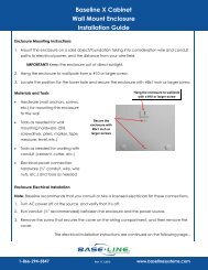
C-series Wall Mount Cabinets<br />
The C-series wall mount cabinet is designed for outdoor or indoor wall or pole mounting. The cabinet features four<br />
screw or bolt mounting holes on tabs above and below the controller chassis as shown below:<br />
The screw holes are approximately ¼ inch x 1/3 inch, and are located 3 inches apart.<br />
If you mount the cabinet outdoors on a pole or post, make sure that the location does<br />
not receive direct spray from sprinkler heads or other water sources.<br />
For detailed dimensions and installation drawings, please visit the Resource Library on<br />
the <strong>Baseline</strong> web site.<br />
Page 14
<strong>BaseStation</strong> <strong>3200</strong> Advanced Irrigation Controller <strong>Manual</strong><br />
Connecting Power and Ground<br />
All C-series wall mount <strong>3200</strong> controllers ship with a conduit-ready ½ inch male exposed thread connection point as<br />
shown in the diagram.<br />
Make all AC power connections in an approved electrical connection junction box, in<br />
accordance with all local electrical codes.<br />
Wire nuts for AC power connections are provided.<br />
X/XS-series Wall Mount Cabinets<br />
The X and XS series wall mount cabinets are designed for outdoor or indoor wall or post mounting. The cabinet<br />
features a center located key-hole main mounting screw assembly for easy mounting, plus an additional center<br />
mounted hole as indicated in the diagram below. The X and XS cabinets feature a ¼ inch air gap between the<br />
chassis and the mounting surface – this reduces long term risk of water incursion or ice-dam buildup during<br />
inclement weather.<br />
For security purposes, all mounting screw heads are protected behind the locked front cover, making theft or<br />
vandalism materially more difficult.<br />
If you mount the cabinet on a post or pole, use an appropriate wood or metal back-plate behind the cabinet to<br />
ensure best long term reliability and secure connections.<br />
Page 15
<strong>BaseStation</strong> <strong>3200</strong> Advanced Irrigation Controller <strong>Manual</strong><br />
Connecting Power and Ground<br />
The main AC power connection is via a small built-in electrical box in the lower left of the enclosure. To access the<br />
electrical box, remove the screw on the right and the panel. The box has a knockout suitable for direct connection<br />
of a ½ inch conduit.<br />
All installations should comply with local and national electrical codes.<br />
Remote Connection Modules and Antennas<br />
If installed, antennas for WiFi, Cell Modem, and Mesh Radio communication units mount through the top access<br />
port. BL Commander permanent receiver unit antennas mount on the right access port (typically factory installed).<br />
To install a communications module in an existing cabinet, consult the documentation that came with the<br />
communications module.<br />
P-series Pedestal Cabinets<br />
The P-series pedestal units are designed to be pad-mounted and come with a concrete template for locating all<br />
mounting bolts, AC power, and two-wire and/or valve wire conduits.<br />
Mounting the Pedestal to a Concrete Platform<br />
All P-series pedestal units are shipped with a metal form to locate mounting bolts and conduits. Install the<br />
concrete pad according to <strong>Baseline</strong>’s specifications with proper slope for drainage. Consult the Resource Library on<br />
the <strong>Baseline</strong> web site at http://www.baselinesystems.com for CAD details and additional instructions.<br />
Page 16
<strong>BaseStation</strong> <strong>3200</strong> Advanced Irrigation Controller <strong>Manual</strong><br />
Remote Connection Modules and Antennas<br />
If installed, antennas for WiFi, Cell Modem, and Mesh Radio communication units mount through the access port<br />
on the left side of the pedestal, and include a stainless steel mounting body to protect antenna cabling and raise<br />
antennas above the top of the pedestal for best signal strength. Consult the Resource Library on the <strong>Baseline</strong> web<br />
site at http://www.baselinesystems.com for CAD details, communications options, and internal locations for<br />
communications modules.<br />
If equipped with a permanently mounted BL Commander handheld remote control receiver kit, the receiver<br />
antenna will be mounted on the upper right side of the pedestal enclosure.<br />
Page 17
<strong>BaseStation</strong> <strong>3200</strong> Advanced Irrigation Controller <strong>Manual</strong><br />
3 – WIRING GUIDELINES<br />
Review this section to find instructions for wiring your <strong>BaseStation</strong> <strong>3200</strong> irrigation controller and for connecting<br />
the standard and optional devices.<br />
Conventional Irrigation Wiring Installation<br />
<strong>BaseStation</strong> <strong>3200</strong>R controllers and <strong>Baseline</strong> 5200R Series Powered biCoders connect directly to conventional 24<br />
VAC irrigation wiring, with one wire for each valve plus a common wire. Additionally, these devices are capable of<br />
communicating to soil moisture sensors over specific terminals that are enabled to search for and communicate<br />
with <strong>Baseline</strong> biSensors.<br />
Conventional Wiring Modules<br />
You can equip each <strong>3200</strong>R controller with 12, 24, 36, or 48 zones, depending on the cabinet.<br />
One 12 or 24 zone connection module fits in a C-series cabinet. An X, XS, or P cabinet accommodates two 12 or 24<br />
zone connection modules.<br />
The terminal designations for each 12 or 24 zone connection module are shown<br />
in the diagram on the right, and include:<br />
• Rain Sensor Port (Normally Closed)<br />
• Two-wire Port (Red and Black)<br />
• Valve Common (x2)<br />
• Master Valve/Pump Start terminals (2, designated VE1 and VE2) – you can<br />
re-address these terminals to control conventional zones if desired<br />
• Sensor-over-valve-wire Ports (x2 for 12 zone, x4 for 24 zone) each with a<br />
status LED<br />
• Standard valve wire ports (x10 for 12 zone, x20 for 24 zone)<br />
Only two zones of any 12 zone block of terminals can be activated concurrently,<br />
plus VE1 and VE2, resulting in a total concurrency of 6 zones for a 24 zone unit.<br />
You can connect <strong>Baseline</strong> biSensors directly to valve wires on the<br />
Sensor-over-valve-wire ports (A1, A2 and B1, B2).<br />
Page 18
<strong>BaseStation</strong> <strong>3200</strong> Advanced Irrigation Controller <strong>Manual</strong><br />
<strong>BaseStation</strong> <strong>3200</strong>R systems have built-in biCoders, and each screw terminal has a unique serial number. These<br />
serial numbers are listed on the wiring label that is included in the unit as shown in the illustration below.<br />
Serial Numbers for zones 1-24 on a BL-5200 Series Powered biCoder<br />
Powered biCoders are preconfigured at the factory to assign zones 1 to 48 (depending on how many zones the unit<br />
is equipped with) to terminals 1 through 48. However, by using the specific serial number, you can re-map any<br />
terminal to any zone address. Refer to Clearing a Previous Zone Number Assignment on page 38.<br />
Connecting Valve Wires and Moisture Sensors over Valve Wires<br />
You can connect <strong>Baseline</strong> biSensors directly to the valve wires on the Sensor-over-valve-wire Ports (A1, A2, B1, B2)<br />
on any 12 or 24 zone connection module.<br />
BL-5200 Series Powered biCoder Wiring Example with One biSensor<br />
1. Power off the two-wire when installing devices. Leave 24 to 36 inches of slack on the two-wire to allow for<br />
easy installation and maintenance.<br />
2. Wire the sprinkler valves directly to the zone connectors and common connector.<br />
3. Locate the biSensor near the closest valve location.<br />
4. Connect the red wire from the biSensor to the power wire or pilot wire of the valve and black wire from the<br />
biSensor to the common wire of the solenoid using the provided 3M Direct Bury Splice Kit DBR/Y connector.<br />
It is critical that polarity be maintained.<br />
Note: Use wire nuts to test communication, and then replace those wire nuts with 3M Direct Bury Splice Kit<br />
DBR/Y connectors before burying.<br />
5. Follow the “Burying the biSensor” instructions, included with the biSensor.<br />
6. Connect the pilot wire from the valve to the A1, A2, B1, or B2 terminals.<br />
7. Press the biSensor update button and verify that the light above the terminal stays on.<br />
8. Assign the biSensor and test its operation. Refer to Assigning Soil Moisture Sensors (biSensors) to Primary<br />
Zones on page 40 and to Testing Soil Moisture Sensors (biSensors) on page 83.<br />
Page 19
<strong>BaseStation</strong> <strong>3200</strong> Advanced Irrigation Controller <strong>Manual</strong><br />
BL-5200 Series Powered biCoder Wiring Example with One biSensor<br />
Expanding with Two-Wire<br />
All <strong>BaseStation</strong> <strong>3200</strong> controllers are capable of communicating with <strong>Baseline</strong> biCoders and biSensors connected to<br />
a two-wire path. Any supported two-wire devices may be connected.<br />
Two-Wire Expansion Example<br />
Page 20
<strong>BaseStation</strong> <strong>3200</strong> Advanced Irrigation Controller <strong>Manual</strong><br />
Connecting to BL-5200R Series Wall Mount biCoders<br />
<strong>Baseline</strong> 5200R Series Powered biCoders are specifically intended for retrofit applications and make combining<br />
several old controllers into a single <strong>BaseStation</strong> <strong>3200</strong> easy and affordable.<br />
BL-5200X-R48 – 48 Zone Wall Mount biCoder in X-Series Cabinet<br />
5200R Series Powered biCoders require 110 VAC power (240 VAC for –INT versions) and are available in C-series<br />
and X/XS-series wall mount cabinets, or P-series pedestals.<br />
Example Wiring Diagram<br />
<strong>BaseStation</strong> <strong>3200</strong>R<br />
BL-5200C-R24<br />
Two-wire Path<br />
biSensor<br />
Valve biCoders<br />
You can connect up to 20 5200R Series Powered biCoders to a single <strong>BaseStation</strong> <strong>3200</strong>, which enables you to<br />
retrofit a large site with multiple controllers into a single <strong>BaseStation</strong> <strong>3200</strong> controller.<br />
Two-Wire Installation<br />
All <strong>BaseStation</strong> <strong>3200</strong> and <strong>3200</strong>R controllers are equipped with a full-function two-wire port capable of connecting<br />
to valve biCoders, powered retrofit biCoders, biSensors, flow meters, and other devices. Because <strong>Baseline</strong>’s biLine<br />
protocol provides full bidirectional communications, you can connect all your irrigation accessories to the same<br />
two-wire path – saving time and money compared to conventional wiring.<br />
Page 21
<strong>BaseStation</strong> <strong>3200</strong> Advanced Irrigation Controller <strong>Manual</strong><br />
Two-Wire Serial Numbers<br />
Each <strong>Baseline</strong> two-wire device has a unique serial number used to identify it. Serial numbers are labeled on all<br />
<strong>Baseline</strong> devices. For devices such as two or four zone biCoders, each output for the biCoder has a unique serial<br />
number, even if it only has one serial number listed on its label.<br />
Serial Numbers for Four-zone biCoder<br />
Two-Wire Connections and Layout<br />
<strong>Baseline</strong> uses a proprietary digital protocol to communicate over two-wire. For the complete and up-to-date<br />
two-wire specification, please refer to the Resource Library on the <strong>Baseline</strong> web site.<br />
Wire Connections<br />
Install all wire connections in compliance with the connector manufacturer’s instructions, and make sure that the<br />
connections are fully waterproof.<br />
Note: Use a 3M Direct Bury Splice Kit DBR/Y connector.<br />
WARNING! Do not connect the two-wire and valve common terminals together because this will damage your<br />
<strong>BaseStation</strong>.<br />
<strong>Baseline</strong> recommends that you allow 24 to 36 inches of strain relief at each wire connection to make valve box<br />
installation and troubleshooting easier and to prevent thermal expansion from pulling connections apart on long<br />
wire runs.<br />
Wire Lengths<br />
Total wire length supported depends on the gauge of the wire used.<br />
Straight Run<br />
Looped Run<br />
Page 22
<strong>BaseStation</strong> <strong>3200</strong> Advanced Irrigation Controller <strong>Manual</strong><br />
Wire Layout<br />
Straight line, star, looped, and combination configurations are supported.<br />
The straight line and the star topology are the recommended layouts. To simplify the illustrations, only the last<br />
device is shown for most configurations. You can assume that other devices, both sensors and biCoders, are<br />
connected along the length of the two-wire path. On a star configuration, the topology has multiple last devices.<br />
Each device must separately meet the distance requirement.<br />
While the loop topology might provide a more robust configuration, it is harder to trace the wiring errors that<br />
might occur. For this reason, <strong>Baseline</strong> recommends the other topologies over the loop.<br />
Straight Line<br />
Looped<br />
Combination<br />
Star<br />
Wire Burial<br />
Bury all wire at a depth appropriate to protect the wire from mechanical damage due to digging or aeration.<br />
<strong>Baseline</strong>’s two-wire system operates under 30 VAC RMS, which is considered safe for shallow burial as outlined in<br />
the National Electric Code. All installations should comply with local electrical codes.<br />
Page 23
<strong>BaseStation</strong> <strong>3200</strong> Advanced Irrigation Controller <strong>Manual</strong><br />
Installing Two-Wire Devices<br />
Wiring a Valve biCoder<br />
<strong>Baseline</strong>’s valve biCoders are designed for direct burial and are tested to<br />
very rigorous standards of durability.<br />
Make all connections in valve boxes fully waterproof. The connectors on<br />
the two-wire path and on the valve side must conform to the 3M Direct<br />
Bury Splice Kit DBR/Y specification and be properly installed.<br />
BiCoders include status and activity LEDs for troubleshooting purposes.<br />
Install the biCoders so you can see those LEDs when the valve box is open.<br />
You can extend valve side wire up to 100 feet, allowing one decoder to<br />
control valves in multiple valve boxes.<br />
1. Power off the two-wire when installing devices. Leave 24 to 36 inches<br />
of slack on the two-wire to allow for easy installation and<br />
maintenance.<br />
2. Place the biCoder in the valve box for convenience and protection.<br />
Valves can be located a maximum of 250 feet from the biCoder<br />
location by using additional 14 gauge wires.<br />
3. Wire valves according to the wiring diagram label on the back of each biCoder.<br />
4. Connect the red and black wire from the biCoder to the corresponding red and black wires on the two-wire<br />
using 3M Direct Bury Splice Kit DBR/Y connectors. It is critical that polarity be maintained.<br />
5. Using the controller, test the connections and assign the biCoders to their proper zone addresses. Refer to<br />
Testing Zones, Valves, and biCoders on page 82 and to Assigning biCoders to Zones on page 38.<br />
Note: The common wires cannot be shared between different biCoders.<br />
Page 24
<strong>BaseStation</strong> <strong>3200</strong> Advanced Irrigation Controller <strong>Manual</strong><br />
Wiring Surge Protection and Lightning Arrestors<br />
Install lightning arrestors according to the specification below. Each lightning arrestor protects roughly a 300 foot<br />
circle, so you should place a lightning arrestor every 600 feet along the wire path. Ground each lightning arrestor<br />
using an appropriate ground rod or plate as per the <strong>Baseline</strong> BL-LA01 Surge Arrestor Specification.<br />
Notes<br />
1 Each surge arrestor protects a 300 foot radius of the two-wire path or backbone wire on <strong>BaseStation</strong> <strong>3200</strong><br />
systems.<br />
2 Install a surge arrestor at the end of the two-wire that is the maximum distance from the controller, or in<br />
a looped topology, at the point of maximum distance from the controller.<br />
3 A stub length must not exceed 50 feet without a surge arrestor (must be within 300 feet of an existing<br />
surge arrestor).<br />
For R-series controllers, a lightning arrestor and appropriate ground rod or plate are required for each moisture<br />
sensor connected to a valve wire that is more than 300 feet from the controller.<br />
Installation Instructions<br />
1. Power off the two-wire when installing devices. Leave 24 to 36 inches of slack on the two-wire to allow for<br />
easy installation and maintenance.<br />
2. Place the surge arrestor in a valve box.<br />
3. Connect the red and black wire from the surge arrestor to the corresponding red and black wires on the<br />
two-wire, making sure that you maintain polarity. You must use 3M Direct Bury Splice Kit DBR/Y connectors<br />
on any two-wire connection in a valve box or buried in soil.<br />
4. Connect the green wire from the surge arrestor to the bare copper using a water proof connection.<br />
Page 25
<strong>BaseStation</strong> <strong>3200</strong> Advanced Irrigation Controller <strong>Manual</strong><br />
5. Attach the bare copper to a ground rod or ground plate and follow proper grounding practices.<br />
Example of Surge Protection Wiring<br />
Wiring a Soil Moisture Sensor (biSensor)<br />
1. Power off the two-wire when installing devices.<br />
2. Wire connections must be 3M Direct Bury Splice Kit DBR/Y connectors for all two-wire connections. All<br />
connections must be installed according to their manufacturer’s instructions.<br />
3. Use polyethylene double-jacketed or UF-B UL PVC double-jacketed<br />
two-conductor solid core wire designed for direct burial systems to<br />
connect the biSensor to the two-wire path.<br />
4. Strip at least ¾ inch of insulation from the wires, and then insert the<br />
wires into the push-in connectors to make a solid connection. Connect<br />
the red and black wire from the biSensor to the red and black wires on<br />
the two-wire, making certain that you maintain the polarity.<br />
5. Verify communications with the <strong>BaseStation</strong> before proceeding.<br />
6. Complete the installation of the 3M Direct Bury Splice Kit DBR/Y<br />
connectors as directed by the manufacturer’s installation guide.<br />
Wiring a Temperature Sensor (biSensor)<br />
1. Power off the two-wire when installing devices. Leave 24 to 36<br />
inches of slack on the two-wire to allow for easy installation and<br />
maintenance.<br />
2. Mount the air temperature sensor to a vertical surface, out of<br />
direct sun light with four screws and suitable wall anchors.<br />
3. Connect the red and black wire from the sensor to the<br />
corresponding red and black wires on the two-wire (it is critical<br />
that polarity be maintained). You must use 3M Direct Bury Splice<br />
Kit DBR/Y connectors on any two-wire connection in a valve box<br />
or buried in soil.<br />
To the two<br />
wire path<br />
Snap DBG<br />
connectors shut<br />
To<br />
biSensor<br />
Page 26
<strong>BaseStation</strong> <strong>3200</strong> Advanced Irrigation Controller <strong>Manual</strong><br />
Wiring a Pump Start Relay<br />
1. Power off the two-wire when installing devices. Leave 24 to 36 inches of slack on the two-wire to allow for<br />
easy installation and maintenance.<br />
2. Locate the biCoder near the irrigation pump relay.<br />
3. Connect the red and black wire from the biCoder to the corresponding red and black wires on the two-wire<br />
using 3M Direct Bury Splice Kit DBR/Y connectors. It is critical that polarity be maintained.<br />
4. Connect one gray wire from the biCoder to one wire of the 24 VAC transformer and the other gray wire to one<br />
side of the pump start relay coil using a 3M Direct Bury Splice Kit DBR/Y connector. The pump start relay<br />
must have a 24 VAC coil.<br />
5. Connect the other wire from the transformer to the other side of the pump start relay coil.<br />
Note: You must purchase a 24 VAC transformer separately.<br />
6. Configure the biCoder as a Master Valve/Pump Start and test its operation. Refer to Configuring a Master<br />
Valve/Pump Start biCoder on page 41.<br />
Wiring a Flow Device<br />
Water flow sensors measure the velocity of the water moving past the sensor and turn this velocity into pulses per<br />
minute. The <strong>BaseStation</strong> calculates the flow rate (the pipe size is accounted for in the K-value and Offset), and<br />
provides an approximate water used number.<br />
Water meters measure the amount of water that flows through the meter and turns this into pulses per gallon,<br />
providing an accurate measurement of the amount of water used. The pulses are measured over time intervals<br />
from which an approximate flow rate is calculated.<br />
The <strong>Baseline</strong> BL-5304 Flow biCoder was designed to work with water flow sensors, and flow sensors provide the<br />
most accurate flow readings. You will see the best results with flow devices that generate more than 100 pulses<br />
per minute.<br />
1. Power off the two-wire when installing devices. Leave 24 to 36 inches of slack on the two-wire to allow for<br />
easy installation and maintenance.<br />
2. Locate the flow biCoder next to the flow sensor/water meter.<br />
Page 27
<strong>BaseStation</strong> <strong>3200</strong> Advanced Irrigation Controller <strong>Manual</strong><br />
3. Connect the red and black wire from the flow biCoder to the corresponding red and black wires on the<br />
two-wire, making sure that you maintain polarity. You must use 3M Direct Bury Splice Kit DBR/Y connectors<br />
for all two-wire wire path connections.<br />
4. Identify the type of flow sensor/water meter and connect its wires to the flow biCoder as shown in the<br />
diagrams. You must use a 3M Direct Bury Splice Kit DBR/Y connector for all of these connections.<br />
5. Verify communications from the <strong>BaseStation</strong> to the flow biCoder and complete the configuration and setup.<br />
Refer to Searching for Flow biCoders (including those associated with a Master Valve) on page 37 and to<br />
Configuring Flow biCoders, Flow Meters, and Flow Sensors on page 41.<br />
Example of a Data Industrial Flow and Similar Two-Wire Sensors<br />
Wiring a Flow Device +NOMV<br />
1. Power off the two-wire when installing devices. Leave 24 to 36 inches of slack on the two-wire to allow for<br />
easy installation and maintenance.<br />
2. Locate the flow biCoder near to the flow sensor/water meter.<br />
3. Use a separate 24 VAC transformer (NOT included) to supply power to the BL-5304NOMV. Attach the<br />
transformer to the two green wires. You must use 3M Direct Bury Splice Kit DBR/Y connectors for all of these<br />
connections.<br />
Note: The unit requires the 24 VAC transformer to function correctly.<br />
4. Connect the orange and white wires to the master valve. You can extend these wires if needed, but do not<br />
exceed 100 feet.<br />
5. Connect the red and black wire from the flow biCoder to the corresponding red and black wires on the<br />
two-wire, making sure that you maintain polarity. You must use 3M Direct Bury Splice Kit DBR/Y connectors<br />
for all two-wire path connections.<br />
6. Identify the type of flow sensor/water meter and connect its wires to the flow biCoder as shown in the<br />
diagrams. You must use 3M Direct Bury Splice Kit DBR/Y connectors for all of these connections.<br />
Page 28
<strong>BaseStation</strong> <strong>3200</strong> Advanced Irrigation Controller <strong>Manual</strong><br />
7. Verify communications from the <strong>BaseStation</strong> to the flow biCoder and complete the configuration and setup.<br />
Refer to Searching for Flow biCoders (including those associated with a Master Valve) on page 37 and to<br />
Configuring Flow biCoders, Flow Meters, and Flow Sensors on page 41.<br />
Wiring a Water Meter<br />
You must use a water meter register that provides at least 10 pulses per gallon. The “pulse reed switch” register<br />
does not generate enough pulses per gallon for meaningful flow measurements for many installations. Netafim<br />
water meters will operate across a large range of flow rates and are a good choice where extended range is<br />
important. You can find more information at http://www.netafim.com, or contact your local distributor.<br />
You must have a water meter and register (pipe size and flow rate) that will generate at least 100 pulses per<br />
minute to have reasonable flow readings, 200 pulses per minute is better.<br />
1. Use a biasing resistor in any three-wire flow meter voltage line.<br />
2. Use the following formula to calculate the K-value, and then enter these values into the appropriate menu on<br />
your <strong>BaseStation</strong> <strong>3200</strong>. Refer to Configuring a Flow Device on page 57.<br />
Examples:<br />
10 Gal/Min and 10 Pulses/Gal<br />
(provides 100 pulses per minute)<br />
K-value = 6.00 (accuracy about 5%)<br />
25 Gal/Min and 10 pulses/gal<br />
(provides 250 pulses per minute)<br />
K-value = 6.00 (accuracy about 2%)<br />
blue<br />
BL-NE01<br />
Blinks when the<br />
two wire is<br />
communicating<br />
yellow<br />
BL-5304<br />
White<br />
Blinks for every 4 th pulse<br />
clear<br />
yellow<br />
Cable shielding must<br />
be fully covered by<br />
water-proof tube<br />
DBR-6 or DBG or<br />
equivalent submersion<br />
proof connectors<br />
To <strong>BaseStation</strong><br />
DBY or equivalent<br />
waterproof connectors<br />
Netafim ‘M’<br />
Water Meter<br />
Page 29
<strong>BaseStation</strong> <strong>3200</strong> Advanced Irrigation Controller <strong>Manual</strong><br />
Pause Devices<br />
Wiring a Pause Button<br />
The pause button provides a convenient way to stop watering. You can install this button in any location where<br />
easy access to the two-wire can be used for a connection. You can install up to three pause devices on a single<br />
<strong>BaseStation</strong> <strong>3200</strong> or <strong>3200</strong>R system to allow convenient access from multiple locations around large sites.<br />
Installation Instructions<br />
1. Mount the pause button box to a vertical wall using four<br />
screws and suitable wall anchors.<br />
2. The weatherproof box accepts ½ inch, non-metallic<br />
electrical conduit. Conduit should be installed to protect<br />
the wires from the two-wire connection to the button box.<br />
Keep in mind direct burial wire is generally not UV<br />
protected and needs to be shielded from the sun.<br />
3. Extend the two-wire to the pause button box using a small<br />
valve box and 3M Direct Bury Splice Kit DBR/Y<br />
connectors.<br />
4. Attach the two-wire coming from the valve box to the<br />
pause button inside a junction box attached to the button<br />
box using waterproof connections<br />
5. Power off the two-wire when installing devices. Leave 24 to<br />
36 inches of slack on the two-wire to allow for easy<br />
installation and maintenance.<br />
6. Mount the pause button to a vertical surface with four screws and suitable wall anchors.<br />
7. Connect the red and black wire from the biCoder to the corresponding red and black wires on the two-wire,<br />
making sure that you maintain polarity.<br />
Wiring a Pause biCoder<br />
Pause biCoders provide a means to pause watering on a program basis through a switch or set of electrical<br />
contacts. When the contacts open, programs can be paused for a pre-set amount of time. You can program each<br />
pause biCoder for a different delay time and to a different set of programs.<br />
Installation Instructions<br />
1. Power off the two-wire when installing<br />
devices. Leave 24 to 36 inches of slack<br />
on the two-wire to allow for easy<br />
installation and maintenance.<br />
2. Locate the biCoder near the normally<br />
closed pause switch.<br />
3. Connect the red and black wire from<br />
the biCoder to the corresponding red<br />
and black wires on the two-wire,<br />
making sure that you maintain polarity.<br />
4. Connect the gray wire from the biCoder<br />
to one wire of the pause switch, and the black wire to the other side of the pause switch.<br />
Page 30
<strong>BaseStation</strong> <strong>3200</strong> Advanced Irrigation Controller <strong>Manual</strong><br />
5. Assign the biCoder as a pause device, and test its operation. Refer to Configuring Pause Devices on page 40.<br />
Wiring a Rain Switch and Other Normally Closed Sensing Devices<br />
All <strong>BaseStation</strong> <strong>3200</strong> controllers are compatible with industry standard normally closed (NC) sensing devices such<br />
as rain switches. You can directly connect these devices to the appropriate terminals on the <strong>3200</strong>, or you can<br />
connect them to the two-wire path using pause biCoders.<br />
Connecting a Rain Switch to the <strong>BaseStation</strong> <strong>3200</strong><br />
Note: Do not wire normally closed sensing devices in series with either the valve common (on R-series units) or<br />
either side of the two-wire path. Wiring devices in this manner defeats the wire health and solenoid current<br />
detection features built into the controller. It also generates incorrect messages and alerts. <strong>Baseline</strong> recommends<br />
that you connect all normally closed sensing devices to the appropriate terminal on the controller or to a pause<br />
biCoder connected to the two-wire path.<br />
Pause Behavior for the Different Connections<br />
The pause behavior of the unit and the associated messages and alerts differ depending on whether the NC device<br />
is connected to a pause biCoder or it is directly connected to a sensor terminal on the <strong>3200</strong>.<br />
• You cannot override a NC sensing device, such as a rain switch, that is directly connected to the <strong>3200</strong>. All<br />
programs will stop watering until the rain switch dries out, which allows the contacts to close again.<br />
• You can connect pause devices, including rain switches, to pause biCoders, and then associate the pause<br />
biCoders with specific programs. After you have created the associations, you can configure the programs to<br />
respond to or ignore the pause devices. Refer to Configuring Pause Devices on page 40.<br />
Watering Behavior for the Different Ports<br />
Rain Sensor Port – On activation, all watering is stopped, and all active programs are terminated. No new irrigation<br />
will be allowed to start until the rain switch deactivates (dries out) and the next start time is reached for a<br />
program. <strong>Baseline</strong> recommends that rain switches connected this way are set to the shortest possible delay<br />
setting.<br />
Note: Smart irrigation using soil moisture sensors will automatically account for the amount of rainfall that actually<br />
penetrates into the soil, which is often quite different from the amount of total rainfall measured by a rain switch.<br />
Flow Sensor Port – On activation, all watering is stopped, and all active programs are terminated. No new<br />
irrigation will be allowed to start until the following conditions are met:<br />
• The flow sensor input is cleared (no longer open)<br />
• The flow alert is cleared in the controller. The flow alert can be cleared remotely using BaseManager central<br />
control, but requires user intervention to protect against landscape damage caused by broken pipes or valves.<br />
• The next start time is reached for a program<br />
Pause Port – On each activation (open circuit), all irrigation is temporarily paused for 4 hours. All active programs<br />
and scheduled watering will resume (where it left off) after the pause period has ended. If the pause port is<br />
activated again during the pause period, the 4 hour pause period will be restarted.<br />
Page 31
<strong>BaseStation</strong> <strong>3200</strong> Advanced Irrigation Controller <strong>Manual</strong><br />
Wireless Rain Sensors<br />
Another popular accessory is a wireless rain sensor. Wireless sensors differ from standard rain sensors because<br />
they require external power, typically 24 VAC.<br />
The various types of wireless rain sensors have different wiring requirements for their receivers. Consult the user<br />
manual for your wireless rain sensor for wiring guidelines.<br />
Removing a Two-Wire Device<br />
If you want to remove a two-wire device, first you must physically disconnect it from the two-wire, and then you<br />
perform a Search operation from the device specific menu in the controller.<br />
Example: If you need to remove a biSensor, physically disconnect the biSensor from the two-wire. Then go to the<br />
controller and turn the dial to the biSensor menu. Perform the steps to search for the biSensor (refer to Searching<br />
for biSensors on page 37). When the controller detects that the biSensor is no longer connected, it will remove the<br />
device from the configuration.<br />
Note: Refer to the Searching for Devices section on page 36 of this manual for the search procedures for the<br />
various two-wire devices.<br />
Page 32
<strong>BaseStation</strong> <strong>3200</strong> Advanced Irrigation Controller <strong>Manual</strong><br />
4 –BASESTATION <strong>3200</strong> INTERFACE<br />
Review this section to get familiar with the layout of the <strong>BaseStation</strong> <strong>3200</strong> interface. This information covers the<br />
components of the front panel, the on-screen help, the features of the main screen, as well as the status colors<br />
and a brief overview of the on-screen reports.<br />
Controller Front Panel Layout<br />
(A) USB Port – The USB port is used for doing Backup<br />
and Restore operations using a USB drive (also known<br />
as a “thumb drive” or a “flash drive”). The USB port is<br />
also used for doing software updates and retrieving<br />
operation log files.<br />
(B) Display – The color display indicates the current<br />
state of the controller and is used to display<br />
programming. This display uses thin-film transistor<br />
(TFT) technology to improve image quality in outdoor<br />
conditions including direct sunlight and low light.<br />
(C) Dial – The dial is used to select the operation or<br />
programming mode of the controller.<br />
(D) Buttons – The buttons are used to select programming elements, change their values, and initiate operations<br />
like testing a zone.<br />
+ Increases the value of the highlighted field or sequences through the available options in the<br />
selected field<br />
- Decreases the value of the selected field, or sequences through the available options in the<br />
selected field<br />
NEXT<br />
PREV<br />
CLR<br />
ENTR<br />
Moves the highlighted selection to the next field on the display<br />
Moves the highlighted field selection to the previously selected field on the display<br />
Performs the function indicated at the bottom of the display, normally a “clear” or “halt”<br />
operation<br />
Saves the setting of the current selection and moves to the next item, or begins the<br />
operation. Read the text at the bottom of the display for specific details.<br />
(E) Status LEDs – These two LEDs indicate the power status of the controller and the internal status of the<br />
controller hardware. The upper light is normally ON, but it may blink when internal diagnostics are run.<br />
(F) Remote Control Port – This connector is used with the BL Commander hand-held radio remote control to<br />
operate valves while away from the controller.<br />
Page 33
<strong>BaseStation</strong> <strong>3200</strong> Advanced Irrigation Controller <strong>Manual</strong><br />
On-Screen Help<br />
At the bottom of every screen, there are instructions that describe how to<br />
use the buttons to change the functions associated with that screen.<br />
The instructions on the screen change depending on the functions and<br />
control requirements.<br />
Auto Run Main Screen<br />
The main screen displays when the dial is in the Auto Run position. This screen shows status for all elements of the<br />
<strong>3200</strong> controller.<br />
Air Temp – Shows “None” if no air temperature sensor is connected to<br />
the system, otherwise shows the current air temperature.<br />
Remote – Indicates the status of remote communications to the <strong>3200</strong>.<br />
Possible indicators include:<br />
• None – No remote communication devices were detected.<br />
• Idle – One or more remote communication devices were detected,<br />
but none are in use at this time.<br />
• BL Commander – A BL Commander remote control is currently active.<br />
• Active – BaseManager central control software is currently connected to and communicating with the<br />
controller.<br />
Two-wire – Indicates the approximate current being supplied to the two-wire path. The value will vary with the<br />
size of the installation and the number of active valves. When the system is not watering, the two-wire status is<br />
OFF.<br />
Flow – If there is no flow meter installed, the controller shows the estimated flow (in brackets) based on the flow<br />
values that have been set for each zone. With one or more flow meters, the controller indicates the total flow<br />
measured. This value is updated once each minute, and is shown without brackets. More detail is available in the<br />
flow reports.<br />
Prog – Shows the status of all programs. Refer to the status color key on the label inside the door of the controller.<br />
MV – Shows the status of each master valve.<br />
Zone Status – The lower section shows the current status of the zones in groups of 50 zones. Press the + or –<br />
button to move between the groups 50 zones.<br />
Page 34
<strong>BaseStation</strong> <strong>3200</strong> Advanced Irrigation Controller <strong>Manual</strong><br />
Status Colors<br />
The following colors display on the Auto Run screen to indicate the status of programs, master valves, flow meters,<br />
and zones.<br />
Idle (watering done)<br />
Active (watering)<br />
Waiting to water<br />
Soaking<br />
Disabled<br />
Paused<br />
Off or Message (blinking)<br />
Unused<br />
On-Screen Reports<br />
Follow the on-screen instructions to access reports from the main screen.<br />
Note: Refer to Notes, Messages, Alerts, and Logs on page 75 for the complete description of the on-screen reports.<br />
1. Turn the dial to the Auto Run position.<br />
2. Press the NEXT or PREV button to cycle through the report pages.<br />
3. Press the + or – button while on any report page to see more reports or messages for each screen.<br />
Note: Messages can include status or warning messages, or serious controller alarms. Messages are prioritized<br />
with the most serious messages automatically being shown first in the Messages report screen.<br />
Page 35
<strong>BaseStation</strong> <strong>3200</strong> Advanced Irrigation Controller <strong>Manual</strong><br />
5 – CONFIGURING DEVICES<br />
After you have finished connecting all your devices, you need to have the controller find those devices so you can<br />
assign them.<br />
The devices that you can attach to the <strong>BaseStation</strong> <strong>3200</strong> have serial numbers. The controller identifies an attached<br />
device by its serial number. After you have searched for the attached devices, you can assign each serial number to<br />
a specific purpose in the controller. For example, you map a valve biCoder’s serial number to the number or<br />
address of the zone that the valve waters.<br />
The <strong>BaseStation</strong> <strong>3200</strong> controller accommodates up to 200 zones, and those zones are identified in the controller<br />
with numbers 1 to 200. These numbers are also referred to as “addresses” because they tell the controller where a<br />
specific device “lives.”<br />
Searching for Devices<br />
Before you can configure any devices such as biCoders or biSensors in the controller, the controller must find those<br />
devices and assign them. You can connect the following types of biCoders and other two-wire devices directly to<br />
the two-wire path:<br />
• Valve biCoders (decoders)<br />
• biSensors (soil moisture sensors)<br />
• Pause biCoders and air temperature sensor<br />
• Flow meters and flow sensors<br />
Searching for biCoders (including Powered biCoders)<br />
1. Turn the dial to the biCoder Menu position.<br />
2. Press the + or – button to select Search in the Find biCoders screen.<br />
3. Press the ENTR button to search for biCoders. The Search may take several<br />
minutes to complete. You will see a status screen like the one shown here<br />
while the search is in progress.”2/New” is displayed signifying 2 new biCoders<br />
were found during this search.<br />
The display shows the number of devices found and the number of ports or<br />
addresses available.<br />
Note: To cancel a search in progress, press the CLR button.<br />
4. Continue to the procedure for assigning the biCoders to zones on page 38.<br />
Page 36
<strong>BaseStation</strong> <strong>3200</strong> Advanced Irrigation Controller <strong>Manual</strong><br />
Searching for biSensors<br />
1. Turn the dial to the biSensor Menu position.<br />
2. Press the NEXT or PREV button to select Assign biSensors.<br />
3. Press the ENTR button.<br />
4. Press the + or – button to select Search.<br />
5. Press the ENTR button. The display shows the number of devices<br />
found and the number of ports or addresses available.<br />
6. Continue to the procedure for assigning the biSensors to primary<br />
zones on page 40.<br />
Searching for Flow biCoders (including those associated with a Master Valve)<br />
In addition to finding flow biCoders, this search finds two-wire flow meters with integrated master valves (both<br />
normally open and normally closed).<br />
1. Turn the dial to the Flow Menu position.<br />
2. Press the NEXT or PREV button to select Flow Device Setup.<br />
3. Press the ENTR button.<br />
4. Press the + or – button to select Search in the Find Flow biCoders<br />
screen.<br />
5. Press the ENTR button to search for flow biCoders. The system verifies<br />
and repairs all flow biCoders that it finds.<br />
6. Continue to the procedure for setting up the flow biCoders on page 41.<br />
Searching for Pause biCoders and Temperature Sensors<br />
1. Turn the dial to the AUX position.<br />
2. Press the NEXT or PREV button to select Temp/Pause.<br />
3. Press the ENTR button.<br />
4. Press the + or – button to select Search.<br />
5. Press the ENTR button to search for pause biCoders. The system<br />
displays the number of pause biCoders that it finds. The serial numbers<br />
of the biCoders are shown in the field at the top of the screen.<br />
Note: You do not need to assign an air temperature sensor to an<br />
address, but you need to perform this search in order to have the<br />
controller find and activate it.<br />
6. If you searched for pause biCoders, continue to the procedure for configuring pause devices on page 40.<br />
Page 37
<strong>BaseStation</strong> <strong>3200</strong> Advanced Irrigation Controller <strong>Manual</strong><br />
Assigning Valve biCoders to Zone Numbers<br />
You can assign any valve biCoder serial number to any zone number.<br />
You may also wish to reassign and/or reorder certain zones in order to properly combine primary and linked zones<br />
in a scheduling group.<br />
The <strong>3200</strong> makes these assignments quick and easy to do, but be sure to document any changes that you make.<br />
Failure to properly document assignments can cause confusion and frustration for maintenance staff.<br />
Zone Numbers are Pre-Assigned in R-Series<br />
When you order a conventionally wired <strong>BaseStation</strong> <strong>3200</strong>R controller, it is pre-programmed at the factory so that<br />
that terminal 1 is assigned to zone 1, terminal 2 is assigned to zone 2, and so on. You can change these zone<br />
numbers to organize scheduling groups, primary, and linked zones to achieve optimal watering behavior.<br />
Note: <strong>Baseline</strong> recommends that you use the Hydrozone Worksheet on page 88 to plan the conversion from your<br />
existing irrigation controller to your new <strong>BaseStation</strong> <strong>3200</strong>.<br />
To change or re-order zone numbers in an R-series unit, perform the steps in Clearing a Previous Zone Number<br />
Assignment on page 38, and then assign each biCoder serial number to the desired zone number. Refer to<br />
Assigning biCoders to Zones on page 38.<br />
Note: The serial numbers for all terminals in <strong>3200</strong>R controllers are shown on the label next to the terminals. The<br />
serial numbers for terminals in 5200R biCoders are shown on the door label.<br />
Assigning biCoders to Zones<br />
After you have wired your valve biCoders to the two-wire and the controller has detected those biCoders, you<br />
need to assign the biCoders to the appropriate address (zone number) in the controller.<br />
Note: If you are converting an existing irrigation controller to a new <strong>BaseStation</strong> <strong>3200</strong>, <strong>Baseline</strong> recommends that<br />
you use the Hydrozone Worksheet on page 88 to plan the conversion.<br />
1. If you have not searched for the biCoders, do that first. Refer to Searching for biCoders (including Powered<br />
biCoders) on page 36.<br />
2. With the dial in the biCoder Menu position and the biCoder List<br />
displayed, press the + or – button to select any unassigned biCoder<br />
serial number.<br />
3. Press the NEXT or PREV button to select an available zone number.<br />
4. Press the ENTR button to assign the selected biCoder to that zone<br />
number.<br />
Note: Use this method to assign master valves MV1-MV4. You can<br />
assign any single or two-valve biCoder as a master valve.<br />
5. When you have finished making changes, turn the dial to the Auto Run position.<br />
Clearing a Previous Zone Number Assignment<br />
You can reassign your biCoders to different zone numbers in order to accurately represent your irrigation system<br />
and the primary zones and scheduling groups that you want to use.<br />
1. If you have not searched for the biCoders, do that first. Refer to Searching for biCoders (including Powered<br />
biCoders) on page 36.<br />
Page 38
<strong>BaseStation</strong> <strong>3200</strong> Advanced Irrigation Controller <strong>Manual</strong><br />
2. With the dial in the biCoder Menu position and the biCoder List displayed, press the + or – button until Clear<br />
displays in the Assign biCoder field.<br />
3. Press the NEXT or PREV button to highlight the Zone Number that you<br />
want to clear.<br />
4. Press the ENTR button.<br />
Note: If you cleared a zone number assignment so you can reassign<br />
certain zones in order to properly combine primary and linked zones in<br />
a scheduling group, return to the Assigning biCoders to Zones<br />
procedure (on page 38) to complete the assignments.<br />
5. When you have finished making changes, turn the dial to the Auto Run<br />
position.<br />
Understanding Zone Statuses<br />
Status codes identify the status of the biCoders that have been configured into the system.<br />
In the Zone Number list, any zones that are configured as primary zones will have a “P” next to them.<br />
Note that the status of each zone is shown in the Zone Number list. The<br />
zone status codes are:<br />
OK – Working properly<br />
OP – Open circuit<br />
SC – Short circuit<br />
ER – Communication error<br />
Adjusting the Valve Power Level for a biCoder<br />
If your irrigation system uses solenoids that have different power requirements, you can adjust the valve power<br />
level of the biCoders that are attached to the zones associated with these solenoids. Typically, you will perform<br />
this task under the guidance of <strong>Baseline</strong> Support.<br />
1. Turn the dial to the AUX position.<br />
2. Press the NEXT or PREV button to move to the Valves option, and then press the ENTR button.<br />
3. Press the + or – button to select the zone and biCoder that you want to adjust.<br />
You can adjust the valve power for any biCoder from a minimum of 1 to a maximum of 3. If a biCoder does not<br />
support this feature, the word “Fixed” displays in the Valve Drive Power field.<br />
4. When you have finished making changes, turn the dial to the Auto Run position.<br />
Page 39
<strong>BaseStation</strong> <strong>3200</strong> Advanced Irrigation Controller <strong>Manual</strong><br />
Configuring Other Devices<br />
Assigning Soil Moisture Sensors (biSensors) to Primary Zones<br />
When you have biSensors connected to your irrigation system, you need to assign each sensor to the zone where it<br />
is located. This zone then becomes a primary zone.<br />
1. If you have not searched for the biSensors, do that first. Refer to Searching for biSensors on page 37.<br />
2. With the dial in the biSensor Menu position and the biSensor List<br />
displayed, press the + or – button to select any unassigned biSensor<br />
serial number.<br />
3. Press the NEXT or PREV button to select the zone, and then press the<br />
ENTR button.<br />
4. Repeat for each primary zone with a biSensor.<br />
Note: When a soil moisture biSensor is assigned, it is initially set for<br />
the Lower Limit water strategy.<br />
To configure your biSensors for watering, refer to Setting Up Soil<br />
Moisture Sensor Based Watering on page 51.<br />
Configuring Pause Devices<br />
You can configure and use up to seven pause devices with the <strong>BaseStation</strong> <strong>3200</strong>. Pause devices are automatically<br />
assigned a number from one to seven when they are found during a search operation.<br />
1. If you have not searched for the pause biCoders, do that first. Refer to Searching for Pause biCoders and<br />
Temperature Sensors on page 37.<br />
2. Turn the dial to the AUX position.<br />
3. Press the NEXT button to move to Temp/Pause, and then press the<br />
ENTR button.<br />
4. If you have multiple pause biCoders attached to your controller, make<br />
sure that the one you want to configure is displayed in the field in the<br />
top left of the screen. If you need to select a different pause biCoder,<br />
press the + or – button until the pause biCoder that you want to<br />
configure is displayed in the field.<br />
5. Press the NEXT button to move to the Pause Delay Time field.<br />
6. Press the + or – button to change the time.<br />
You can set the Pause Delay Time in hour increments between zero and 24 hours. When the pause biCoder<br />
detects that its contacts have been opened, the specified programs will pause and suspend all watering. The<br />
controller waits for the specified pause delay time, and then it checks the pause biCoder again. If the contacts<br />
are still open, it waits again for the pause delay time, but if the contacts are closed, the paused programs will<br />
resume watering.<br />
7. Press the NEXT button to move to the list of programs, and then press the NEXT or PREV button to select the<br />
program that you want change.<br />
Page 40
<strong>BaseStation</strong> <strong>3200</strong> Advanced Irrigation Controller <strong>Manual</strong><br />
8. When the program is selected, press the + or – button to change between Y (yes) and – (no).<br />
Note: If you want to turn off the pause biCoder, select the Pause Delay Time field, and then press the CLR<br />
button.<br />
9. When you have finished making changes, turn the dial to the Auto Run position.<br />
Configuring Flow biCoders, Flow Meters, and Flow Sensors<br />
Flow Meters and Flow Sensors are configured on the Flow Menu dial position. Refer to Configuring a Flow Device<br />
on page 57 for detailed instructions for assigning and configuring Flow biCoders, Flow Meters, and/or Flow<br />
Sensors.<br />
Configuring a Master Valve/Pump Start biCoder<br />
1. If you have not searched for the biCoders, do that first. Refer to Searching for biCoders (including Powered<br />
biCoders) on page 36.<br />
2. With the dial in the biCoder Menu position and the biCoder List<br />
displayed, press the + or – button to select the Master Valve /Pump<br />
Start biCoder that you wish to configure.<br />
3. Press the NEXT or PREV button to select the Master Valve Zone you<br />
would like to configure.<br />
4. Press the ENTR button.<br />
Note: You can configure a single, dual, or pump start biCoder as a<br />
master valve.<br />
5. When you have finished making changes, turn the dial to the Auto Run position.<br />
Associating a Master Valve/Pump Start biCoder with Programs<br />
1. If you have not configured the biCoders with the master valves, do that first. Refer to Configuring a Master<br />
Valve/Pump Start biCoder on page 41.<br />
2. Turn the dial to the MV/Pump Start position.<br />
3. Press the + or – button to select the Master Valve /Pump Start that<br />
you want to turn on when a specified program runs.<br />
4. Press the NEXT or PREV button to move to the list of programs, and<br />
then press the NEXT or PREV button to select the program that you<br />
want change.<br />
5. When the program is selected, press the + or – button to change<br />
between Y (yes) and – (no).<br />
Note: You can associate a master valve with one or all programs.<br />
6. When you have finished making changes, turn the dial to the Auto Run position.<br />
Page 41
<strong>BaseStation</strong> <strong>3200</strong> Advanced Irrigation Controller <strong>Manual</strong><br />
6 – INITIAL PROGRAMMING<br />
After you have configured your devices as described in the previous section, you are ready to start the initial<br />
programming on your <strong>BaseStation</strong> <strong>3200</strong> controller. Review the information in this section to learn how to set up<br />
time-based watering for your zones, how to enable the soak cycles, and set up your programs. If you are using a<br />
soil moisture sensor, be sure to read the information about setting up soil moisture sensor based watering<br />
including the information about the watering strategies.<br />
Power Cycling or Restarting the Controller<br />
If the controller goes into an abnormal state and does not respond, you might need to restart it.<br />
1. Turn the dial to OFF.<br />
2. Press and hold the – and + and ENTR buttons for approximately 5 seconds.<br />
3. After the screen goes blank, release the buttons.<br />
4. Turn the dial to Auto Run. The controller restarts.<br />
Setting the Controller Date and Time<br />
Set or change the controller date and time to match the current date and time.<br />
1. Turn the dial to the Date/Time position.<br />
2. Press the NEXT or PREV button to move to the NEXT field.<br />
3. Press the + or – button to change the value in the field.<br />
4. Press the ENTR button to save settings.<br />
WARNING! Changing the date and time can cause watering events to be<br />
missed.<br />
5. When you have finished making changes, turn the dial to the Auto Run<br />
position.<br />
Checking the Software Version on Your Controller<br />
Turn the dial to AUX.<br />
The version number of the software displays at the<br />
top of the screen.<br />
Software updates are free for the life of any <strong>Baseline</strong><br />
controller as long as the hardware is compatible.<br />
<strong>Baseline</strong> will periodically release software updates<br />
that enhance the usefulness of our products or fix<br />
the occasional bug.<br />
Page 42
<strong>BaseStation</strong> <strong>3200</strong> Advanced Irrigation Controller <strong>Manual</strong><br />
To determine whether the software version on your controller is different from the currently released version, go<br />
to the <strong>Baseline</strong> web site (www.baselinesystems.com). Type software update in the Search field and click Submit. In<br />
the search results, click the <strong>BaseStation</strong> <strong>3200</strong> Software Update link. Review the information on that page, to find<br />
out what the current software version is and then compare that with the version on your controller.<br />
If you find that an updated software version is available and you want to replace the software on your controller<br />
with the new version, refer to Updating the Controller Software on page 73.<br />
Setting Up Time-Based Watering<br />
The <strong>BaseStation</strong> <strong>3200</strong> provides the following methods for controlling the amount of water that is applied to a zone:<br />
• Watering based on time and schedule<br />
• Watering based on soil moisture<br />
Even if you are planning to use soil moisture method to control how much water to apply, you still need to set up<br />
the time-based watering schedule for your zones.<br />
When you assign a biCoder to a zone number, default settings are given to the zone. You can view and modify<br />
these values by turning the dial to the Zone Water Times position.<br />
After you have assigned all the biCoders to zone numbers, each zone will have this default program.<br />
Setting Up a Timed Zone<br />
By default, all zones are set up as timed. If the mode of a zone was changed to linked or primary, you can use this<br />
procedure to change the zone mode back to timed.<br />
Implications for scheduling groups:<br />
• If you change a zone in the middle of your scheduling group from linked to timed, the linked zones will<br />
continue to water as a group, but the zone that was changed to timed will now water on a timed schedule.<br />
• If you change a primary zone to timed, all zones that are linked to that primary zone will be changed to timed.<br />
To set up a timed zone<br />
1. Turn the dial to the Zone Water Times position.<br />
2. Press the + or – button to select the zone that you want to change the mode for.<br />
3. Press the NEXT button to move to the Zone Mode field.<br />
4. Press the + or – button until Timed displays in the Zone Mode field.<br />
5. When you have finished making changes, turn the dial to the Auto Run position.<br />
Modifying the Default Settings for a Zone<br />
You can configure the following settings for each zone:<br />
Zone – When this field is highlighted, press the + or – button to select a different zone number.<br />
biCoder – Set this field to Enabled when you want to use a zone for normal operation. Change the field to Disabled<br />
to keep it from running during maintenance or other conditions.<br />
Page 43
<strong>BaseStation</strong> <strong>3200</strong> Advanced Irrigation Controller <strong>Manual</strong><br />
Zone Mode – There are three modes for zones in the <strong>BaseStation</strong> <strong>3200</strong>.<br />
Timed • The default for newly assigned zones. In this mode, you can program the zone to water in a<br />
time-based manner (like other irrigation controllers).<br />
Primary • This zone type is used for the lowest numbered zone in a zone scheduling group. Making<br />
changes to a primary zone will automatically make corresponding changes in all linked<br />
zones.<br />
• A biSensor can only be assigned to a primary zone.<br />
Linked • A linked zone waters according to the programming of the primary zone that it is linked to.<br />
If zone 2 is linked to primary zone 1, then it will use the same programming as zone 1.<br />
• A linked zone must have a higher number than the primary zone that it is linked to.<br />
Water Time – You can set the zone water time from 1 minute to 23 hours 30 minutes. Linked zones are<br />
programmed as a tracking ratio or percentage of the primary zone. For a primary zone set to 60 minutes, a linked<br />
zone that is programmed at 150% would have a water time of 90 minutes. Linked zone ratios range from 30% to<br />
1000%. Changing the primary zone to a new water time will adjust linked zones by their tracking ratios.<br />
Program – You can create up to twenty programs (A to T) for ultimate flexibility. A zone may be assigned to any<br />
program. Linked zones are automatically assigned to the program of their primary zone and cannot be changed<br />
independently.<br />
To modify the default settings for a zone<br />
1. Turn the dial to the Zone Water Times position.<br />
2. Press the + or – button to select the zone that you want to change.<br />
3. Press the NEXT or PREV button to move to the field that you want to<br />
change.<br />
Note: The Help at the bottom of the screen indicates what options are<br />
available for the field and what buttons you need to press to select<br />
those options.<br />
4. When you have finished making changes, turn the dial to the Auto Run<br />
position.<br />
Assigning a Primary Zone<br />
A primary zone is the lowest numbered zone in a zone scheduling group. Making changes to a primary zone will<br />
automatically make corresponding changes in all linked zones. A primary zone also designates the zone where a<br />
sensor is located (if you have one installed).<br />
Prerequisites<br />
• biCoders have been assigned to zones.<br />
• If you are using soil moisture sensors, they have been installed and detected by the controller.<br />
• You know the number of the zone that waters the area where the sensor is installed.<br />
• If you are planning to include this primary zone in a scheduling group, make sure that the zone is at an address<br />
with a lower number than the other zones within the same scheduling group. For example, if zones 1 – 50 are<br />
in one scheduling group, zone 1 would be the primary zone. For retrofits, you may need to renumber your<br />
zones in order to meet this requirement. Refer to Clearing a Previous Zone Number Assignment on page 38.<br />
Page 44
<strong>BaseStation</strong> <strong>3200</strong> Advanced Irrigation Controller <strong>Manual</strong><br />
To assign a primary zone<br />
1. Turn the dial to the Zone Water Times position.<br />
2. Press the + or – button to select the zone that you want to assign as a<br />
primary zone.<br />
3. Press the NEXT button to move to the Zone Mode field.<br />
4. Press the + or – button until Primary displays in the Zone Mode field.<br />
5. Repeat steps 2 – 4 for each primary zone with a biSensor.<br />
After you assign the primary zone, if you turn the controller dial to the<br />
biCoder Menu, you will notice a P next to the zone number of the<br />
primary zone.<br />
Linking Zones (Creating a Scheduling Group)<br />
To make programming easier and more structured, the <strong>BaseStation</strong> <strong>3200</strong> provides a way to group zones that have<br />
similar watering requirements. You create a scheduling group by designating the lowest zone number of the group<br />
as the primary zone and then configuring each of the following zones in the group as linked. These settings allow<br />
you to change the program for the primary zone and automatically apply those changes to each of the linked<br />
zones. For example, if your group has 10 zones, you only need to make changes to the primary zone, and then all<br />
the changes will be automatically applied to the other 9 zones.<br />
1. Perform the procedure in Assigning a Primary Zone (on page 44) first.<br />
2. Turn the dial to Zone Water Times.<br />
3. Press the + or – button to select the zone that you want to link.<br />
4. Press the NEXT button to move to the Zone Mode field.<br />
5. Press the + button to change the entry in the field so it shows Link to<br />
Primary Zone #.<br />
6. To continue linking zones, press the ENTR button to move to the next<br />
zone.<br />
7. Repeat steps 4 and 5 until you have linked all the zones in the group to<br />
the primary zone for that group.<br />
8. When you have finished making changes, turn the dial to the Auto Run position.<br />
Adjusting the Water Time Tracking Ratio of Linked Zones<br />
You can change the water time tracking ratio of a linked zone in order to allow different run times for zones within<br />
a group of linked zones. When the tracking ratio of a linked zone is set to 75% of the primary, the zone will run for<br />
that percentage of the run time of the primary zone (for example, if the primary zone is set to water for 60<br />
minutes and the linked zone tracking ratio is set to 75%, the linked zone will water for 45 minutes because 75% of<br />
60 is 45). If you change the run time for the primary zone, each linked zone will be adjusted according to its<br />
tracking ratio value.<br />
1. Turn the dial to Zone Water Times.<br />
2. Press the + or – button to select the zone that you want to adjust the<br />
water time tracking ratio for.<br />
3. Press the NEXT button to move to the Water Time field.<br />
4. Press the + button to change the entry in the field.<br />
Page 45
<strong>BaseStation</strong> <strong>3200</strong> Advanced Irrigation Controller <strong>Manual</strong><br />
Note: As you change the time in the field, the ratio percentage changes to indicate how the time is related to<br />
the amount of time that the primary zone is scheduled to water. The example in the illustration shows that 45<br />
minutes is 100% of the watering time scheduled for zone 2, so you know that zone 2 is also scheduled to water<br />
for 45 minutes. In this example, if you were to reduce the time in the Water Time field to 22 minutes, the ratio<br />
would change to 50% to indicate that 22 minutes is approximately half of the 45 minutes that zone 2 is<br />
scheduled to water.<br />
5. To adjust the water time tracking ratio for other zones, press the ENTR button to move to the next zone.<br />
6. Repeat steps 4 and 5 until you have adjusted the water time tracking ratio for all the zones in the group.<br />
7. When you have finished making changes, turn the dial to the Auto Run position.<br />
Using Soak Cycles<br />
Because each type of soil has a different rate at which it can absorb water, you should set up the cycle time and<br />
soak time (“soak cycles”) for your zones to ensure that water soaks into the soil instead of being wasted. For<br />
example, if you are applying water at 0.4 inch per hour to an area of clay soil that can only absorb water at 0.2 inch<br />
per hour, the water that does not soak into the soil will either run off or evaporate.<br />
It is especially important to use appropriate soak cycles when you are watering a slope.<br />
The <strong>BaseStation</strong> <strong>3200</strong> allows you to quickly configure soak-cycle times for your zones.<br />
To enable the default soak-cycle settings<br />
1. Turn the dial to the Soak Cycle position.<br />
2. Press the + or – button to select the zone that you want to enable the default soak-cycle settings for.<br />
Note: When you set the soak-cycle times for a primary zone, the soak cycles will also be set for all linked<br />
zones. The cycle time for linked zones is calculated based on the tracking ratio of the primary zone cycle time.<br />
The soak times will be the same as that of the primary zone.<br />
3. Press the CLR button. If soak-cycle settings were already configured, pressing CLR will remove those settings.<br />
Press CLR again to update the fields with the default soak-cycle settings. The controller automatically sets the<br />
cycle time to one-third the zone run time and the soak time to twice the cycle time.<br />
4. When you have finished making changes, turn the dial to the Auto Run position.<br />
In this example, the settings are shown for a 60-minute zone run time.<br />
Primary zone 2 waters for 20 minutes, and then allows that water to soak<br />
in for 40 minutes. While zone 2 is soaking, other zones can run. After the<br />
40 minutes soak time, zone 2 will be allowed to run another 20 minutes<br />
after any zone that is currently running finishes.<br />
With these settings, zone 2 completes its 1 hour of watering in three,<br />
20-minute segments, with at least a 40 minute soak time between them.<br />
When there are many zones in a program, zones will be cycled and soaked<br />
until all have been completed. Zones that have completed their soak cycles<br />
are prioritized higher that zones that are still waiting to water so the first zones to start watering will be the first to<br />
complete.<br />
Page 46
<strong>BaseStation</strong> <strong>3200</strong> Advanced Irrigation Controller <strong>Manual</strong><br />
To change soak-cycle settings for timed zones<br />
You can change the soak and cycle times for timed zones as needed to match the zone conditions (soil type and<br />
slope).<br />
1. Turn the dial to the Soak Cycle position.<br />
2. Press the + or – button to select the timed zone that you want to change the soak-cycle settings for.<br />
3. Perform one of the following:<br />
a. If soak cycles have been disabled for the zone, press the CLR button to enable the default soak-cycle<br />
settings.<br />
b. If you want to change the displayed values, continue with step 4.<br />
4. Press the NEXT or PREV button to move to the field that you want to change.<br />
5. Press the + or – button to change the value in the field.<br />
6. When you have finished making changes, turn the dial to the Auto Run position.<br />
To disable soak cycles<br />
1. Turn the dial to the Soak Cycle position.<br />
2. Press the + or – button to select the zone that you want to disable the soak cycle for.<br />
Note: When you disable the soak cycle for a primary zone, soak cycle is disabled for all linked zones. The<br />
controller skips the linked zones when you press the + or – button to select a zone.<br />
3. Press the CLR button. The soak-cycle settings are removed. The Cycle Time field is blank and OFF displays in<br />
the Soak Time field.<br />
4. When you have finished making changes, turn the dial to the Auto Run position.<br />
Setting Up Programs<br />
The <strong>BaseStation</strong> <strong>3200</strong> supports 20 programs. The controller identifies each program with a letter of the alphabet<br />
starting at A and going up to T. By default, all zones assigned in the controller are associated with program A. To<br />
associate zones with another program, refer to Associating Zones with a Program on page 51.<br />
In many irrigation controllers, you set up the run times and the watering schedules in the programs, but in the<br />
<strong>BaseStation</strong> <strong>3200</strong>, run times are configured for the individual zones, and a program provides the schedule for when<br />
the associated zones will water. The schedule has the following components:<br />
Start Times – Each program can have up to eight start times in a 24 hour period. Start times are set in 15 minute<br />
increments from the top of the hour. If there is no start time, then the program is considered to be OFF or disabled<br />
and no watering will be allowed on the zones of that program.<br />
Water Windows – Water windows are used to select when watering will or will not be allowed. You can configure<br />
water windows on a weekly basis (having the same water window settings for each day of the week) or on a daily<br />
basis, where you can set each day of the week for a specific water window schedule.<br />
Day Intervals – If there are watering restrictions in your area, the controller might have a pre-configured day<br />
interval option that will enable you to comply with the restrictions. Options are a seven day schedule, even days of<br />
the month, odd days of the month, odd days of the month excluding the 31 st day of the month, and historical ET<br />
calendar (explained in the topic on setting up historical ET-based watering for a program on page 49).<br />
Page 47
<strong>BaseStation</strong> <strong>3200</strong> Advanced Irrigation Controller <strong>Manual</strong><br />
To set up the start times for a program<br />
1. Turn the dial to the Start Times position.<br />
2. Press the + or – button to select the program that you want to set up<br />
start times for.<br />
3. Press the NEXT button to move to one of the start time fields.<br />
4. Press the + or – button to set the time in the field.<br />
5. Press the CLR button to remove a start time from the field.<br />
6. When you have finished making changes, turn the dial to the Auto Run<br />
position.<br />
To set up the water windows for a program<br />
Water windows tell the controller when watering is allowed and not allowed. You can set water windows for either<br />
Weekly (shown on the screen shot) or daily – when moving from weekly to daily, the weekly settings are copied to<br />
each day of the week.<br />
Selecting daily water windows gives you hourly control of watering for each day of the week, and for each<br />
program. A white square will pause watering for that hour.<br />
1. Turn the dial to the Start Times position.<br />
2. Press the + or – button to select the program that you want to set up water windows for.<br />
3. Press the NEXT button to select the Set Water Windows option, and<br />
then press the ENTR button. The Water Windows screen displays.<br />
4. Press the NEXT button to move to the Water Windows field, and then<br />
press the + or – button to select either Weekly or Daily.<br />
Note: If you use “Weekly” to set up the water windows and then you<br />
decide to convert to “Daily,” the weekly settings are copied to each<br />
day of the week.<br />
Selecting daily water windows gives you hourly control of watering for<br />
each day of the week and for each program.<br />
5. Press the NEXT button to move to the Set All To field, and then press the + or – button to select either ON or<br />
OFF. These settings change all the boxes in the grid to blue (allow watering) or white (do not allow watering).<br />
6. To make changes to the individual boxes in the grid, press the NEXT button. The color of the number in the<br />
first box of the grid changes to red (indicating that you can change the setting in that box).<br />
a. If you want to change the water setting for the time/day represented by that grid, press the + button.<br />
b. If you want to move to next box in the grid, press the NEXT button.<br />
Note: If you want to set up daily water windows, start by setting a basic profile in weekly mode, and then<br />
change to daily mode to modify specific days (like a mow day). Pressing the ENTR button will maintain the<br />
current selected field and advance through the days of the week.<br />
7. Press the CLR button to return to the Start Times screen.<br />
8. When you have finished making changes, turn the dial to the Auto Run position.<br />
Page 48
<strong>BaseStation</strong> <strong>3200</strong> Advanced Irrigation Controller <strong>Manual</strong><br />
To set up the day intervals for a program<br />
1. Turn the dial to the Day Intervals position.<br />
2. Press the + or – button to select the program that you want to set up<br />
day intervals for.<br />
3. Press the NEXT button to move to the field where you select the<br />
interval that you want.<br />
4. Press the + button to move through the options, and then stop when<br />
the option that you want to use is displayed in the field.<br />
Note: Refer to the topic for setting up the Historical ET Calendar mode<br />
on page 49.<br />
5. For some options, you need to set up the schedule. Press the NEXT button to move to the schedule. The<br />
selected day is highlighted blue.<br />
6. Press the + or – button to change that day from a watering day (indicated by Y for “yes”) to a non-watering<br />
day (indicated by – for “no”).<br />
7. When you have finished making changes, turn the dial to the Auto Run position.<br />
Note: A program that is started on one day will continue to run until it completes, even if it needs to continue<br />
to the next day, which may or may not be a watering day. For example, if a six-hour program starts at 10 PM<br />
on Monday, it will finish at 4 AM on Tuesday, even if Tuesday is not a watering day.<br />
To set up historical ET-based watering for a program<br />
In the <strong>BaseStation</strong> <strong>3200</strong>, one of the Day Interval modes for a program is Historical ET Calendar. Evapotranspiration<br />
(ET) refers to the loss of moisture from the soil by evaporation and by the transpiration of plants. Factors such as<br />
air temperature, humidity, solar radiation, and wind speed affect the rate at which ET occurs. Scientists with the<br />
National Oceanic and Atmospheric Administration (NOAA) continuously monitor climate data in all regions of the<br />
United States. When this data is averaged over a 30 year period, historical ET values are generated for each month<br />
of the year.<br />
The Historical ET Calendar mode enables you to set up a watering schedule for the entire year that compensates<br />
for seasonal changes without your having to adjust times and frequency multiple times throughout the year. Bear<br />
in mind that a historical ET-based watering schedule works best in regions where landscapes are irrigated all year.<br />
If you set up a run time that applies ½ inch of water and then you change the frequency of watering based on the<br />
historical ET needs for your area, the controller will water deeply and less frequently and encourage the roots of<br />
your plants to grow deep.<br />
Prerequisites<br />
• Set zone water times that will apply ½ inch of water during each watering cycle.<br />
• Get the historical ET deficit data for your region. Consult with your local Agricultural Cooperative Extension<br />
office – you can find a national register of the extension offices at: http://www.csrees.usda.gov/Extension/<br />
• Split each month of the year in half and determine how frequently you will need to water in order to replace,<br />
but not exceed, the amount of moisture used by your plant material since the last irrigation event. Use the ET<br />
deficit data to determine the watering frequency.<br />
Note: If you combine the Historical ET Calendar mode with the upper limit watering strategy using biSensors,<br />
you will have a very effective watering schedule. The biSensor will monitor the soil moisture in real-time and<br />
compensate for non-historical weather behavior by making fine adjustments to the run time.<br />
Page 49
<strong>BaseStation</strong> <strong>3200</strong> Advanced Irrigation Controller <strong>Manual</strong><br />
Instructions<br />
1. Turn the dial to the Day Intervals position.<br />
2. Press the + or – button to select the program that you want to set up historical ET-based watering for.<br />
3. Press the NEXT button to move to the field where you select the interval.<br />
4. Press the + button to move through the options, and then stop when Historical ET Calendar is displayed in the<br />
field.<br />
5. Press the NEXT button to move to the Day Interval<br />
Calendar. The selected day interval is indicated by a<br />
colored box on a number. The date field displays the half<br />
month that is represented by that number.<br />
Note: The calendar displays 12 boxes that represent the<br />
months of the year. The numbers in the boxes represent<br />
the day intervals for first half and second half of the<br />
month.<br />
a. To increase or decrease the selected day interval,<br />
press the +/– buttons.<br />
b. To move to and select a different day interval, press the NEXT button.<br />
6. When you have finished configuring the Historical ET Calendar settings, turn the dial to the Auto Run position.<br />
Note: If you set up multiple programs to use the Historical ET Calendar settings, be sure to set the program<br />
start dates so the interval is staggered. Refer to Setting up the day intervals for a program on page 49.<br />
To adjust the water budget for programs<br />
In order to provide a full range of functionality, the <strong>BaseStation</strong> <strong>3200</strong> controller software includes an option to<br />
increase or decrease the amount of time all zones in a program will water. However, we recommend that you use<br />
other methods for adjusting the amount of water that your irrigation system is putting down. A healthier way to<br />
water turf is to always water deep (about the same amount of time) and change the frequency of watering to<br />
maintain the correct moisture level. Use the Day Intervals schedule for better results. Refer to Setting up the day<br />
intervals for a program on page 49.<br />
1. Turn the dial to the AUX position.<br />
2. Press the NEXT or PREV button to select Budget, and then press the<br />
ENTR button. The Program Water Time Budget screen displays and<br />
shows all programs set to 100%.<br />
3. Press the NEXT button to move to the program where you want to<br />
adjust the percentage.<br />
4. Press the + or – button to change the percentage. You can set the<br />
percentage between 25 and 200%.<br />
5. When you have finished making changes, turn the dial to the Auto Run<br />
position.<br />
Page 50
<strong>BaseStation</strong> <strong>3200</strong> Advanced Irrigation Controller <strong>Manual</strong><br />
Associating Zones with a Program<br />
In your landscape, you probably have zones that need to be watered every day (such as those that water turf<br />
areas) and other zones that need to be watered less frequently (such as shrub borders). In order to manage these<br />
different watering schedules, it is best to create separate programs for the turf and the shrubs and then associate<br />
the appropriate program with the zones that water the specific landscape area.<br />
Prerequisites<br />
• The zones have been correctly assigned in the controller.<br />
• You know the numbers of the zones that water the specific landscape areas.<br />
1. Turn the dial to the Zone Water Times position.<br />
2. Press the + or – button to select the zone that you want to associate with a program.<br />
3. Press the NEXT button to move to the Program/ML1 field.<br />
4. Press the + or – button to select the program that you want the zone to be associated with.<br />
5. Repeat steps 2 – 4 to associate all zones with a specific program.<br />
6. When you have finished making changes, turn the dial to the Auto Run position.<br />
Setting Up Soil Moisture Sensor Based Watering<br />
You can take the guesswork out of your watering decisions by setting up soil moisture sensor based watering. The<br />
biSensor measures soil moisture where the plants need it – at the root level.<br />
When you have a biSensor installed, the <strong>BaseStation</strong> <strong>3200</strong> enables you to set up one of the following water<br />
strategies:<br />
• Timed – Waters without biSensor control, but provides a log of daily moisture levels.<br />
Note: Be sure to use the Timed water strategy with new grass. After the root zone is established, you can<br />
change to one of the other strategies.<br />
• Lower Limit – Prevents watering until the moisture level drops below the limit, and then a full water cycle will<br />
run. The user sets and manages the limit.<br />
• Lower Limit Auto – Waters the same as Lower Limit, but the controller sets and manages the limit. The user<br />
can set an adjustment factor if desired.<br />
• Upper Limit – Allows watering at each start time, but the run time is adjusted to replenish the moisture to<br />
field capacity. The user sets and manages the limit.<br />
• Make sure that you have soak cycles properly set up for the zones that will be using soil moisture based<br />
watering. In addition to allowing the applied water to soak into the soil, soak cycles allow time for the<br />
water to reach the biSensor depth so the soil moisture readings are accurate. Refer to Using Soak Cycles<br />
on page 46.<br />
• Upper Limit Auto – Waters the same as Upper Limit, but the controller sets and manages the limit. The user<br />
can set an adjustment factor if desired.<br />
Page 51
<strong>BaseStation</strong> <strong>3200</strong> Advanced Irrigation Controller <strong>Manual</strong><br />
Prerequisites for Watering with Soil Moisture Sensors<br />
• Your biSensors are installed and assigned in the <strong>BaseStation</strong> <strong>3200</strong>. Make sure to assign the correct biSensor to<br />
its primary zone. Making an incorrect assignment here will result in unexpected and confusing water behavior.<br />
Refer to Assigning Soil Moisture Sensors (biSensors) to Primary Zones on page 40.<br />
• You have created scheduling groups (a primary zone with linked zones) that combine areas with similar<br />
watering needs (hydrozones). For example, the zones that water the softball field would be in one scheduling<br />
group and the zones that water the north lawn between the sidewalk and the building would be in another<br />
scheduling group. Refer to Linking Zones (Creating a Scheduling Group) on page 45.<br />
To configure your biSensors and set up watering strategies<br />
1. Turn the dial to the biSensor Menu position.<br />
2. Press the NEXT button to select Configure biSensors, and then press the<br />
ENTR button. The Configure biSensors screen displays.<br />
3. If you have more than one biSensor installed and assigned, verify that the<br />
correct sensor is selected. If the biSensor that you want to configure is<br />
not displayed in the field, press the + or – button to select the correct<br />
one.<br />
4. Press the NEXT button to move to the Water Strategy field, and then<br />
press the + or – button to select the water strategy that you want to use.<br />
IMPORTANT NOTE! If you select any of the Upper or Lower Limit strategies, be sure to read the information<br />
below for a complete explanation of these strategies.<br />
5. Press the NEXT button to move to the Calibrate field.<br />
• If you selected Lower or Upper (one of the <strong>Manual</strong> strategies), you can set this field to OFF or Once (to<br />
indicate a single calibration cycle).<br />
• If you selected Lower Auto or Upper Auto, you can set this field to Next to run a calibration cycle on the<br />
next start time, or to Monthly after the system completes the first calibration cycle.<br />
• If you want to run an additional calibration cycle during the month, change Monthly to Next.<br />
Note: Calibration cycles require that soak cycles be enabled. When you set these watering strategies, soak<br />
cycles will be automatically enabled. You may change the settings to meet your specific needs, but if you<br />
disable the soak cycles, the calibration cycle will fail.<br />
6. Press the NEXT button to move to the Adjust field. If you selected Lower Auto or Upper Auto, you can set the<br />
limit wetter or drier to adjust the moisture to your specific needs.<br />
7. Press the NEXT button to move to the <strong>Manual</strong>/Auto Limit field.<br />
• If you selected Lower or Upper (one of the <strong>Manual</strong> strategies) and there is a calibration cycle scheduled,<br />
this field displays Pending. If you set the Calibration field to OFF, you can press the NEXT button to select<br />
the <strong>Manual</strong> Limit field and then press the + or – button to change the value in the field.<br />
• If you selected Lower Auto or Upper Auto, you cannot change this field.<br />
8. When you have finished making changes, turn the dial to the Auto Run position.<br />
Note: If for any reason the biSensor becomes damaged or fails (12 hours of failed data or communication) the<br />
corresponding primary zone and linked zones will water based on a timed operating mode which is based on<br />
set water times and program schedule.<br />
Page 52
<strong>BaseStation</strong> <strong>3200</strong> Advanced Irrigation Controller <strong>Manual</strong><br />
Understanding Upper and Lower Limit Watering Strategies<br />
Lower Limit<br />
This water strategy provides an excellent way to achieve healthy, deep-rooted grass. You can either set the lower<br />
limit manually or you can have the controller perform a calibration cycle in order to calculate the limit. Set the<br />
lower limit at the maximum allowable depletion moisture level, just before the lawn begins to stress or wilt.<br />
<strong>Manual</strong><br />
When you choose the Lower water strategy, you must set and then manage<br />
the lower watering limit. This water strategy works well when you are not<br />
constrained by specific water days. Schedule the program to water every day,<br />
and then let the biSensor determine which days to skip by monitoring the<br />
moisture level. The controller only waters when the moisture level has<br />
dropped below the lower limit, and then a full water cycle runs.<br />
The best way to set the lower limit is to have the controller do an initial<br />
calibration cycle. Set the Calibrate field to Once. The calibration cycle will run<br />
during the first normally scheduled run time that is at least two days after the<br />
biSensor installation. The system sets an initial lower limit based on the calibration.<br />
Auto<br />
When you choose the Lower Auto water strategy, the controller sets and<br />
manages the lower water limit. The controller schedules a monthly calibration<br />
cycle to adjust the limit for seasonal changes to soil and plants. This<br />
calibration cycle occurs on the first water time of the new month. Setting this<br />
water strategy also schedules an initial calibration cycle for the next start time<br />
that is at least two days after the biSensor installation. You have the option to<br />
adjust the auto limit by entering a value in the Adjust field. This adjustment of<br />
up to +/– 2% is added to the limit to make the soil a little wetter or a little<br />
drier than the controller set limit.<br />
Lower Limit Programming Requirements<br />
• Set zone run times to apply ½ inch of water<br />
• Set program to start every day of the week (biSensor will block watering until it is needed)<br />
• Enable soak-cycles<br />
• Use the default lower limit water strategy to begin with<br />
• The first calibration cycle occurs on the first start time after a biSensor has been installed for at least 48<br />
hours.<br />
• A calibration cycle will calculate limits 12 to 15 hours after watering is complete on the primary zone.<br />
• A calibration cycle will extend the programmed zone water time if needed to determine the soil<br />
saturation point - if the ground is very dry (or if the run time is too short), the run time could extend to<br />
twice the programmed time.<br />
• If a calibration cycle cannot determine the soil saturation point, the calibration cycle will fail – posting an<br />
alert and setting a default limit.<br />
Page 53
<strong>BaseStation</strong> <strong>3200</strong> Advanced Irrigation Controller <strong>Manual</strong><br />
Lower Limit Watering Behaviors<br />
• It is uncertain which days of the week when watering will occur – use water windows to specify a mow day.<br />
• The water run time for a program is fixed, so the end time is predictable to the extent that multiple programs<br />
may all be trying to water on the same day.<br />
Upper Limit<br />
This water strategy varies the zone water time each time the program runs in order to apply enough water to raise<br />
the moisture level to field capacity. Soak cycles are critical for this mode because the controller monitors the<br />
moisture level as water is applied. At the end of each soak cycle, the controller determines whether an additional<br />
water cycle is needed. After the upper limit has been reached, the controller will water for an additional 50% of<br />
the primary zone run time to compensate for distribution uniformity issues and increased deep watering.<br />
<strong>Manual</strong><br />
When you choose the Upper water strategy, you must set and manage the<br />
upper watering limit. You can have the controller perform an initial calibration<br />
cycle to establish the starting limit value. This calibration cycle will be run on<br />
the first start time, two days after the biSensor installation date. After the<br />
initial calibration cycle has been run, you must monitor the moisture levels<br />
and plant health so you can make adjustments as needed.<br />
Upper limit watering starts a watering cycle on each start time for the primary<br />
zone and adjusts the watering time to raise the moisture level back up to the<br />
upper limit (field capacity). The controller increases or decreases the water<br />
time, but it never adjusts more than twice your initial water time.<br />
Auto<br />
When you choose the Upper Limit Auto water strategy, the controller<br />
performs a monthly calibration cycle to determine the field capacity of the soil<br />
due to seasonal changes in the soil and plants. This calibration cycle will be<br />
run on the first start time of the new month. When this strategy is first set, it<br />
will perform an initial calibration cycle during the next start time that is at<br />
least two days after the biSensor installation date.<br />
Upper Limit Programming Requirements<br />
• Set the zone run times to apply ½ inch to ¾ inch of water<br />
• Set the program to use Historical ET Calendar day intervals (or alternately, specific days of the week)<br />
• Enable soak cycles<br />
Upper Limit Watering Behaviors<br />
• The water schedule is known as far as what days watering will occur – use water windows to specify a mow<br />
day.<br />
• The water run time for a program is variable, so the end completion time is not predictable – if there are<br />
completion time constraints, this may not be a good water strategy.<br />
Page 54
<strong>BaseStation</strong> <strong>3200</strong> Advanced Irrigation Controller <strong>Manual</strong><br />
Complying with Water Restrictions<br />
There are times and seasons when water restrictions are placed on areas. Keeping a green and healthy landscape<br />
during these restrictions is best achieved with deep rooted turf! Train your grass before the crisis to grow deep<br />
roots by watering deeply and only when the grass needs it.<br />
Note: If you are in an area that is under severe water restrictions, do not try to water using biSensors – set the<br />
water strategies to Timed and apply permitted water. You can use the moisture graphs to track the moisture<br />
depletion rate.<br />
The first step in understanding how to keep the controller from watering when it should not is to identify under<br />
what conditions it will allow watering. The <strong>BaseStation</strong> <strong>3200</strong> controller will start a program when all of the<br />
following conditions have been met:<br />
• Program start time<br />
• Valid water day<br />
• If a moisture biSensor is used, then the moisture level at the program start time is less than the limit<br />
• There isn’t an event day<br />
• There isn’t a rain sensor stop condition<br />
• There isn’t another controller stop condition (such as a high flow shutdown)<br />
The program will run to completion, spanning days if needed. The running program may be paused for some<br />
period of time by one of the following conditions, after which it will resume until it has completed:<br />
• Water window (white square)<br />
• Pause switch or pause biCoder<br />
• Turning the dial to make a programming change – when the dial is left in a programming position, the<br />
controller will return to run mode in two hours just as if the dial had been move back to Auto/Run.<br />
If there are specific days that cannot be used for watering, use one of the following methods to meet those<br />
requirements:<br />
• Start programs after midnight and provide enough time for them to complete during a single day so they do<br />
not span into the next day.<br />
• Use water windows to block out specific days.<br />
Page 55
<strong>BaseStation</strong> <strong>3200</strong> Advanced Irrigation Controller <strong>Manual</strong><br />
Setting Up Event Days<br />
The <strong>BaseStation</strong> <strong>3200</strong> supports eight event days. An event day stops all watering and keeps all programs from<br />
starting on that date. You can schedule an event day up to a year in advance.<br />
To add a new event day<br />
1. Turn the dial to the Event Days position.<br />
2. Press the NEXT or PREV button to move to an empty event day box.<br />
3. Press the + or – button to set the desired date.<br />
4. When you have finished making changes, turn the dial to the Auto Run<br />
position.<br />
To edit existing event days<br />
1. Turn the dial to the Event Days position.<br />
2. Press the NEXT or PREV button to move to an event day box.<br />
3. Press the + or – button to set the desired date.<br />
4. When you have finished making changes, turn the dial to the Auto Run position.<br />
To remove an event day<br />
1. Turn the dial to the Event Days position.<br />
2. Press the NEXT or PREV button to move to an event day box.<br />
3. Press the CLR button to remove the date.<br />
4. When you have finished making changes, turn the dial to the Auto Run position.<br />
Page 56
<strong>BaseStation</strong> <strong>3200</strong> Advanced Irrigation Controller <strong>Manual</strong><br />
7 – FLOW MANAGEMENT & MONITORING<br />
The <strong>BaseStation</strong> <strong>3200</strong> provides an extensive set of flow monitoring and management capabilities to help<br />
understand how water is being used and to reduce the effects of pipeline breaks and sprinkler malfunctions. It can<br />
monitor actual water flow rates and compare them against the expected or<br />
design flow rates and provide alerts and perform actions when limits or<br />
boundaries are exceeded. The system can reduce the overall completion<br />
time of a watering cycle by running the number of zones that best use the<br />
available water at each minute of the watering cycle.<br />
To access the main menu for flow management, turn the dial to the Flow<br />
Menu position.<br />
Using a flow device to monitor water flow rates and water used is the best<br />
way to manage this precious resource, but even without a flow device, the<br />
<strong>BaseStation</strong> <strong>3200</strong> has many capabilities that can improve the efficiency of your system.<br />
Configuring a Flow Device<br />
1. Search for the flow device.<br />
a. Turn the dial to the Flow Menu position.<br />
b. Press the NEXT or PREV button to select Flow Device Setup.<br />
c. Press the ENTR button. The Flow Device Setup screen displays.<br />
d. Press the + or – button until Search displays<br />
in the Configure Flow Device field.<br />
e. Press the ENTR button to search for flow<br />
biCoders. The system indicates how many<br />
flow devices it finds.<br />
2. Press the + or – button to move through the list<br />
of flow devices, and stop when the serial<br />
number of the flow device that you want to set<br />
up displays in the field.<br />
Note: The system assigns a number from 1 to 4<br />
to each flow device in the order that they are<br />
found. This number is used when programming the flow device or when referring to the flow device from<br />
other menus.<br />
3. Press the NEXT button to move to the Enable field, and then press the + or – button to select either Yes or No.<br />
Note: If the flow biCoder is disabled, it will not be used in high flow checking, but it will continue to<br />
accumulate data about the amount of water used.<br />
4. Press the NEXT button to move to the Use Internal NOMV field. If the flow device that you are setting up has<br />
a normally open master valve (NOMV), you can enable it by pressing the +/– buttons. If the flow device does<br />
not have an NOMV, the field displays “na” to indicate that the setting does not apply.<br />
Page 57
<strong>BaseStation</strong> <strong>3200</strong> Advanced Irrigation Controller <strong>Manual</strong><br />
Note: If flow device #1 has a NOMV, the system assigns the device as master valve 1 (MV1). This flow device<br />
can monitor flow rates and automatically shut down the NOMV on a high flow condition, independent of the<br />
state of the controller. If you want the device to provide 24x7 monitoring, you must supply power to the<br />
device either from an external 24 VAC source or by setting the two-wire to be always on.<br />
5. Press the NEXT button to move to the K-Value field. If the flow device was purchased from <strong>Baseline</strong> and is<br />
either a PFS-series or BHM-series device, the K-value and Offset are pre-programmed into the device and will<br />
be read and set during the Search operation.<br />
Note: Make sure that each flow device in the system is configured with a K-value and Offset pair or with a<br />
pulses/gal value. These numbers are used to take the pulses generated by the flow device and turn them into<br />
a more useable value, such as gallons per minute (or total gallons). To find these numbers, refer to the<br />
documentation that came with the flow device.<br />
6. Press the NEXT button to move to the Two-Wire Always On field. If the two-wire is set to always on, it will<br />
only turn off when the controller dial is moved to the OFF position.<br />
Note: Press the CLR button to return to the top menu level from a sub menu.<br />
7. When you have finished making changes, turn the dial to the Auto Run position.<br />
Flow Device Limits and Monthly Budget<br />
You can set limits and budgets for each individual flow device and for the mainline that these flow devices attach<br />
to. Refer to the procedure for setting up the mainline on page 61.<br />
You can set the following values for each flow device on the Flow Device Limits screen:<br />
Note: The step-by-step procedure for configuring the flow device limits is on page 59.<br />
• Design Flow – In this field, you can enter the specified gallons per<br />
minute (GPM) for the point of connection (POC) that supplies water<br />
through the flow device to the rest of the irrigation system. The<br />
<strong>BaseStation</strong> <strong>3200</strong> uses this value to manage the number of concurrent<br />
zones so that the water source is used as efficiently as possible. If you<br />
set this value to zero, you cannot use this GPM amount to control zone<br />
concurrency.<br />
• High Flow Limit – The system uses the GPM value in this field as a<br />
critical limit. When this value is greater than zero, the system<br />
compares the limit against the measured reading from the flow device<br />
every minute. If the flow rate reading exceeds the limit for three or four minutes in a row, the system<br />
generates an alert.<br />
If you set the Shut Down field to Y (yes), then programs using this POC will be stopped and corresponding<br />
master valves (MVs) will be shut off when the flow rate exceeds the limit.<br />
If the flow device is a Flow+NOMV type, the flow limit is programmed into the flow device. The system<br />
monitors the high flow limit and the NOMV shuts off when the flow limit is exceeded. When a flow device is<br />
connected to external power, the NOMV will shut off even when the controller off or powered down.<br />
• Unscheduled Flow Limit – When this limit is set to greater than zero, the system monitors the flow 24x7 for<br />
any flow that does not correspond to running programs.<br />
When you have a NOMV, you can set this limit to allow some flow that is off schedule, such as from manual<br />
taps or hose bibs.<br />
If the flow exceeds the limit for several minutes, the system generates an alert. If you set the Shut Down field<br />
to Y (yes), then the associated MVs will turn off.<br />
Page 58
<strong>BaseStation</strong> <strong>3200</strong> Advanced Irrigation Controller <strong>Manual</strong><br />
• Monthly Budget – When the value in this field is greater than zero, the system monitors the total water used<br />
during a single month.<br />
If the monthly water used exceeds this number, an alert is generated. If you set the Shut Down field to Y (yes),<br />
then the associated MVs shut off and water is stopped until the first of the next month.<br />
To configure the flow device limits<br />
1. Turn the dial to the Flow Menu position.<br />
2. Press the NEXT button to select Flow Device Limits, and then press the<br />
ENTR button. The Flow Device Limits screen displays.<br />
3. If the device in the Flow Device field is not the one that you want to<br />
configure, press the + or – button to select a different flow device.<br />
4. Press the NEXT button to go to the Design Flow field, and then press<br />
the + button to enter the amount of flow in gallons per minute (GPM)<br />
that is allowed through the point of connection for the irrigation<br />
system.<br />
Note: Press and hold the + button or the - button to rapidly increase or decrease the number in the field.<br />
5. Press the NEXT button to go to the High Flow Limit field, and then press the + button to enter the maximum<br />
amount of flow in gallons per minute.<br />
6. Press the NEXT button to go to the Shut Down field. If you want programs using this POC to be stopped and<br />
corresponding MVs shut off when the flow rate exceeds the limit, press the + button to enter a Y (yes) in the<br />
field. If you do not want excessive flow to shut down the system, leave the – in the field.<br />
Note: If you want to exit the Flow Device Limits screen, press the CLR button.<br />
7. Press the NEXT button to go to the Unscheduled Flow Limit field, and then press the + button to enter the<br />
maximum amount of unscheduled flow in gallons per minute.<br />
8. Press the NEXT button to go to the Shut Down field. If you want the associated MVs to turn off when an<br />
unscheduled flow exceeds this limit, press the + button to enter a Y (yes) in the field. If you do not want<br />
excessive flow to shut down the system, leave the – in the field.<br />
9. Press the NEXT button to go to the Monthly Budget field, and then press the + button to enter the maximum<br />
amount of water that can be used per month in gallons.<br />
10. Press the NEXT button to go to the Shut Down field. If you want the associated MVs to turn off when the<br />
amount of water used exceeds this limit, press the + button to enter a Y (yes) in the field. If you do not want<br />
excessive water use to shut down the system, leave the – in the field.<br />
11. When you have finished making changes, turn the dial to the Auto Run position.<br />
Mainline Setup<br />
The <strong>BaseStation</strong> <strong>3200</strong> supports four mainlines. By default, the mainlines are numbered in the controller from 1 – 4<br />
regardless of whether your system has more than one. All programs and flow devices are automatically assigned to<br />
mainline #1, but you can change the settings to match your irrigation system. For more information about<br />
changing how the mainlines are associated with your programs and flow devices, refer to Multiple Flow Devices<br />
and Mainlines on page 64.<br />
The mainline is the primary water management feature in your irrigation system. In the <strong>BaseStation</strong> <strong>3200</strong>, you can<br />
configure the following settings for the mainline in order to better manage flow in your irrigation system.<br />
Note: The step-by-step procedure for setting up the mainline is on page 61.<br />
Page 59
<strong>BaseStation</strong> <strong>3200</strong> Advanced Irrigation Controller <strong>Manual</strong><br />
• Design Flow GPM – This field is the flow rating for the mainline in<br />
gallons per minute (GPM). This flow is likely different from the design<br />
flow of the POC/flow device. When a mainline has multiple POCs of<br />
different capacity, the controller uses the constrained design flow to<br />
determine the actual available flow for watering.<br />
For example, consider the following design flows:<br />
Flow Device #1 = 50 GPM<br />
Flow Device #2 = 75 GPM<br />
Mainline #1 = 100 GPM<br />
In the example, the controller would use 100 GPM for managing zone concurrency unless flow device #2 was<br />
shut off (over budget). In this case, the controller would use 50 GPM.<br />
• Pipe Fill Time – This field represents the time that it takes to fill the pipe and achieve a steady flow rate after a<br />
valve change. The default value is 2 minutes, but you can set it to any value between 1 and 30 minutes. Zone<br />
changes are made at the top of the minute, and the zone is considered stable after the pipe fill time. One<br />
minute after the pipe fill time, a valid flow is calculated (over the last minute interval).<br />
• Limit by Flow – When the Limit by Flow field is set to Y (yes) the controller will use the design flow of the<br />
individual zones (or learned flow) and will turn on zones that are waiting to water until their design flow is<br />
equal or less than the available flow on the mainline. For example, with 100 GPM available, the system can run<br />
three zones at 30 GPM and a fourth at 10 GPM at one time – later there may be two zones at 30 GPM and one<br />
at 20 GPM (the system cannot always hit 100 GPM exactly).<br />
• Flow Variance Settings<br />
• High Alarm – You can set the high variance limit to Off or to any value between 1% and 100%. During<br />
normal program watering, the controller compares the sum of the design flow (or learned flow) from all<br />
running zones against the measured flow of the flow device (or the sum of all flow devices supplying<br />
water to the mainline). The measured flow may be higher or lower than the expected flow. When the<br />
ratio becomes greater than the variance, then an alarm is generated. For example, if the expected flow is<br />
50 GPM, and the High Alarm variance is 10%, then the acceptable flow range is up to 55 GPM (10% of 50<br />
GPM is 5 GPM).<br />
• High Shutdown – Set this field to Y (yes) to have the system shut down when the high variance exceeds<br />
the limits. A high alarm prompts the system to determine the zone (or set of zones) that is causing the<br />
high flow variance. The currently running zones are marked as “suspects” and are shut off. The program<br />
continues to water with another set of zones and one of the suspect zones. If the variance is within limits,<br />
the zone will be marked as good and watering will continue. If the variance is out of limit, then the zone<br />
will be marked as a failure and shut down. This method allows watering to continue almost without<br />
interruption, while isolating the faulty zone or zones.<br />
• Low Alarm – You can set the low variance limit to Off or from 1% to 100%. During normal program<br />
watering, the controller compares the sum of the design flow (or learned flow) from all running zones<br />
against the measured flow of the flow device (or the sum of all flow devices supplying water to the<br />
mainline). The measured flow may be higher or lower than the expected flow. When the ratio becomes<br />
greater than the variance, then an alarm is generated. For example, if the expected flow is 50 GPM, and<br />
the Low Alarm variance is 10%, then the acceptable flow range is down to 45 GPM (10% of 50 GPM is 5<br />
GPM).<br />
• Low Shutdown – Set this field to Y (yes) to have the system shut down when the low variance exceeds the<br />
limits. A low alarm prompts the system to determine the zone (or set of zones) that is causing the low<br />
flow variance. The currently running zones are marked as “suspects” and are shut off. The program<br />
continues to water with another set of zones and one of the suspect zones. If the variance is within limits,<br />
Page 60
<strong>BaseStation</strong> <strong>3200</strong> Advanced Irrigation Controller <strong>Manual</strong><br />
the zone will be marked as good and watering will continue. If the variance is out of limit, then the zone<br />
will be marked as a failure and shut down. This method allows watering to continue almost without<br />
interruption, while isolating the faulty zone or zones.<br />
To set up the mainline<br />
1. Turn the dial to the Flow Menu position.<br />
2. Press the NEXT button to select Mainline Setup, and then press the ENTR button. The Mainline Setup screen<br />
displays.<br />
3. In the Mainline Number field, press the + or – button to select the number of the mainline that you want to<br />
set up.<br />
4. Press the NEXT button to go to the Design Flow GPM field, and then press the + button to enter the amount<br />
of flow in gallons per minute (GPM) that is allowed through the mainline for the irrigation system.<br />
Note: Press and hold the + button or the – button to rapidly increase or decrease the number in the field.<br />
5. Press the NEXT button to go to the Pipe Fill Time field, and then press the + button to enter the amount of<br />
time that it takes to fill the pipe and achieve a steady flow rate after a valve change.<br />
6. Press the NEXT button to go to the Limit by Flow field. If you want the controller to use the mainline design<br />
flow to determine how many zones can run concurrently, press the + button to enter Y (yes).<br />
7. Press the NEXT button to go to the High Alarm field. If you want to set an alarm for a high flow variance<br />
condition, press the + button to enter a percentage in the field.<br />
Example: If the expected flow is 50 GPM, and the High Alarm field is set to 10%, then the acceptable flow<br />
range is up to 55 GPM (10% of 50 GPM is 5 GPM). A flow amount over 55 GPM would trigger the high flow<br />
variance alarm.<br />
8. Press the NEXT button to go to the High Shutdown field. If you want<br />
the system to shut down when a high flow is detected, press the +<br />
button to enter Y (yes).<br />
9. Press the NEXT button to go to the Low Alarm field. If you want to set<br />
an alarm for a low flow variance condition, press the + button to enter<br />
a percentage in the field.<br />
Example: If the expected flow is 50 GPM, and the Low Alarm field is set<br />
to 10%, then the flow can decrease to 45 GPM (10% of 50 GPM is 5<br />
GPM). A flow amount below 45 GPM would trigger the low flow<br />
variance alarm.<br />
10. Press the NEXT button to go to the Low Shutdown field. If you want the system to shut down when a low flow<br />
is detected, press the + button to enter Y (yes).<br />
11. When you have finished making changes, turn the dial to the Auto Run position.<br />
Managing Concurrent Zones<br />
In the <strong>BaseStation</strong> <strong>3200</strong>, you manage the number of zones that can run concurrently at the following levels:<br />
• Mainline Flow Level – When you set up the design flow for the mainline and then set the Limit by Flow field to<br />
Y (yes), the system uses the mainline design flow to determine how many zones can run concurrently. Refer to<br />
Mainline Setup overview on page 59.<br />
• Controller and Program Level – If you want the controller to water more than one zone at a time, you must<br />
configure the Zone Concurrency settings at the controller and program level.<br />
Page 61
<strong>BaseStation</strong> <strong>3200</strong> Advanced Irrigation Controller <strong>Manual</strong><br />
Even if your system does not have a flow device, you can still use the Zone Concurrency settings at the<br />
controller and program level without having to input design flows for all zones and the mainline.<br />
When you have one or more flow devices, a good strategy is to set the controller and program concurrency<br />
limits to a reasonable maximum and then lower specific programs that have some special considerations (such<br />
as, the mainline branch is smaller, longer, or you want to slow the<br />
completion time of a program, or if the two-wire length is very long<br />
and you want to control the voltage drop by limiting the current to<br />
those valves).<br />
Example<br />
The illustration shows the maximum concurrent zones set to 7. If your<br />
system had no water supply constraints, program A, B, and C could start at<br />
the same time, and only 7 zones would run concurrently. If program B was<br />
running by itself, only 3 zones would run concurrently.<br />
To manage concurrent zones by controller and program<br />
1. Turn the dial to the Flow Menu position.<br />
2. Press the NEXT button to select Zone Concurrency, and then press the ENTR button. The Zone Concurrency<br />
screen displays.<br />
3. In the Maximum Concurrent Zones field, press the + button to enter a number that represents the number of<br />
zones that can run at the same time on this controller.<br />
Note: Consider electrical and water constraints when you are setting up concurrent zones.<br />
4. Press the NEXT button to move to the list of programs.<br />
5. Press the NEXT button to move to the program that you want to set concurrent zones for.<br />
6. Press the + button to enter a number that represents the number of zones that can run at the same time for<br />
this program.<br />
7. When you have finished making changes, turn the dial to the Auto Run position.<br />
Learning Flow<br />
With one or more flow devices, the <strong>BaseStation</strong> <strong>3200</strong> has the ability to do a learn flow cycle to determine the flow<br />
for zones. You can run the learn flow cycle either by program or for individual zones. You can set up the learn flow<br />
cycle to be delayed from 15 minutes to 23 hours and 45 minutes. You can set multiple programs to learn the flow,<br />
each at a different time, or the same time. When you schedule a learn flow cycle, it only runs one time.<br />
Learning the Flow by Program<br />
1. Turn the dial to the Flow Menu position.<br />
2. Press the NEXT button to select Program Learn Flow, and then press<br />
the ENTR button. The Program Learn Flow screen displays.<br />
3. Press the NEXT button to move to the program that you want to<br />
schedule a learn flow cycle for.<br />
4. Press the + button to set the learn time in 5 minute increments in the<br />
future, up to about 24 hours.<br />
Note: At the 24 hour point the status will return to Not Yet.<br />
5. When you have finished setting up the learn flow cycle, turn the dial to the Auto Run position.<br />
Page 62
<strong>BaseStation</strong> <strong>3200</strong> Advanced Irrigation Controller <strong>Manual</strong><br />
IMPORTANT NOTE! The learn flow cycle does not start until you turn the dial to the Auto Run position. Depending<br />
on how many zones a program has, the learn flow cycle could take more than an hour to complete.<br />
When the learn flow cycle begins, it will pause any running programs (on that mainline), and it will run one zone at<br />
a time to learn its flow. It will take several minutes to learn the flow for each zone. For example, if the pipe fill time<br />
is two minutes, here are the learn flow steps for each zone.<br />
1. Turn on the zone.<br />
2. After two minutes, the pipe has filled and the flow has stabilized.<br />
3. Take a one minute stable flow reading at the end of the third minute.<br />
4. Take a second stable reading at the end of the fourth minute.<br />
5. If the two readings are within 5%, take the average and set this as the zone learn flow value and set the status<br />
as passed.<br />
6. If the values differ by more than 5%, take a third reading at the end of the fifth minute.<br />
7. Average the readings and set the learn flow value.<br />
8. If the readings are within 5% of the average, set the zone status to pass, otherwise set it to failed and issue an<br />
alert.<br />
9. When the learn flow cycle completes, the values are displayed in the Zone Flow Setup screen.<br />
Learning the Flow by Zone<br />
For each zone, you can either set the design flow manually, or you can configure it to run through a learn flow<br />
cycle and have its design flow set automatically. You should reconfigure the design flow for a zone whenever you<br />
change out a sprinkler or emitter on a zone or whenever the learn flow cycle fails for a zone.<br />
1. Turn the dial to the Flow Menu position.<br />
2. Press the NEXT button to select Zone Flow Setup, and then press the<br />
ENTR button. The Zone Flow Setup screen displays.<br />
3. In the Zone field, press the + button to select the zone that you want to<br />
schedule a learn flow cycle for.<br />
Note: If you already entered the design flow for this zone, the design flow<br />
GPM amount displays in the Flow Rate field. After a learn flow cycle is<br />
completed successfully, the design flow value is replaced by the learn<br />
flow value. The learned flow value is recorded on the screen so this<br />
information is not lost when someone manually changes the design flow<br />
value.<br />
4. Press the NEXT button to go to the Learn Flow Cycle field. If the system already ran a learn flow cycle for this<br />
zone, the status of that cycle (complete or failed) displays in the field. To schedule a learn flow cycle, press the<br />
+ button to advance the delay time by 5 minutes.<br />
5. When you have finished scheduling the learn flow cycle, turn the dial to the Auto Run position.<br />
IMPORTANT NOTE! The learn flow cycle does not start until you turn the dial to the Auto Run position.<br />
Page 63
<strong>BaseStation</strong> <strong>3200</strong> Advanced Irrigation Controller <strong>Manual</strong><br />
Multiple Flow Devices and Mainlines<br />
With the <strong>BaseStation</strong> <strong>3200</strong>, you can independently manage four mainlines separate from each other. A mainline is<br />
defined as a primary water delivery pipe that delivers water to a specific set of zones (valves and heads). Mainlines<br />
are considered to be different and separate if the water in one mainline cannot be delivered to the zones of<br />
another mainline.<br />
You can program sites with this topology so that each mainline operates independently. In this scenario, a learn<br />
flow cycle can be running on mainline 1, while a high flow shutdown event is occurring on mainline 2, but the other<br />
mainlines and their programs/zones will continue to operate normally.<br />
If you want your irrigation system to have this capability,<br />
you need to assign the various pieces of your system to a<br />
corresponding mainline. A mainline can have flow devices,<br />
master valves, and programs (which contain the zones<br />
connected to the mainline). The illustration to the right<br />
shows how you can configure a site that has two<br />
mainlines. Note that mainline 2 has two POCs, each with a<br />
master valve and flow device.<br />
You will find it helpful to have a diagram of your site when<br />
you are configuring the <strong>BaseStation</strong> <strong>3200</strong>.<br />
Most sites are served by a single mainline, meaning that all water is distributed through a single pipe, even though<br />
there may be multiple POCs that supply water to that pipe or mainline. For this reason, mainline 1 is the default for<br />
all flow devices, master valves, and programs.<br />
To assign mainline numbers to your flow devices and programs<br />
1. Turn the dial to the Flow Menu position.<br />
2. Press the NEXT button to select Mainline<br />
Configure, and then press the ENTR button.<br />
The Mainline Configure screen displays.<br />
3. Press the + or – button to assign the mainline<br />
to the displayed flow device.<br />
4. Press the NEXT button to move to list of<br />
programs.<br />
5. If you need to assign any of your programs to a<br />
mainline other than #1, press the NEXT button<br />
until the box for that program is selected, and then press the + or – button to assign the mainline number to<br />
the program.<br />
Note: If you want to exit the Mainline Configure screen, press the CLR button.<br />
6. When you have finished making changes, turn the dial to the Auto Run position.<br />
Page 64
<strong>BaseStation</strong> <strong>3200</strong> Advanced Irrigation Controller <strong>Manual</strong><br />
8 – MANUAL OPERATIONS<br />
The <strong>BaseStation</strong> <strong>3200</strong> has several options that enable you to manually control your irrigation system. You can force<br />
a program to start, stop a program that is actively watering or set the next start date for a program.<br />
You can also manually water a single zone, all zones, or the zones of a program. The <strong>Manual</strong> Water is useful for<br />
doing a walk-about test of multiple valves, or for applying additional water for a short period of time to a specific<br />
zone.<br />
<strong>Manual</strong>ly Running a Program<br />
<strong>Manual</strong> Run is used to force a program to start, stop a program that is actively watering, or set the NEXT start date<br />
for a program when you are using the Historical ET Calendar interval setting.<br />
Note: Programs that do not use the Historical ET Calendar mode have a fixed schedule and are modified in the Day<br />
Intervals dial position. Refer to the topic for setting up the day intervals for a program on page 49.<br />
Forcing a Program to Start<br />
1. Turn the dial to the <strong>Manual</strong> Run Program position.<br />
2. Make sure that the field at the top of the screen says Start or Stop<br />
Program. If another option displays in that field, press the + button to<br />
change the option to Start or Stop Program.<br />
3. Press the NEXT button to move to the list of programs.<br />
4. Press the NEXT button to move to a stopped program that you want to<br />
start.<br />
5. Press the + button to change the program’s status to Running.<br />
6. Turn the dial to the Auto Run position.<br />
Stopping an Active Program<br />
1. Turn the dial to the <strong>Manual</strong> Run Program position.<br />
2. Make sure that the field at the top of the screen says Start or Stop Program. If another option displays in that<br />
field, press the + button to change the option to Start or Stop Program.<br />
3. Press the NEXT button to move to the list of programs.<br />
4. Press the NEXT button to move to a running program that you want to stop.<br />
5. Press the + button to change the program’s status to Stopped.<br />
6. Turn the dial to the Auto Run position.<br />
Page 65
<strong>BaseStation</strong> <strong>3200</strong> Advanced Irrigation Controller <strong>Manual</strong><br />
Setting the Next Start Date for a Program<br />
If you are using the Historical ET Calendar interval for multiple programs, you can use this option to set staggered<br />
start dates for each program.<br />
1. Turn the dial to the <strong>Manual</strong> Run Program position.<br />
2. Press the + button to change the option in the top field to Set Next<br />
Program Start Date.<br />
3. Press the NEXT button to move to the list of programs. The default<br />
start date for any program that is currently set to Historical ET<br />
Calendar displays next to that program’s letter.<br />
Note: The default start date is based on the day interval established<br />
for this time frame in the Historical ET Calendar settings. You cannot<br />
set the program start date further in the future than the default start<br />
date.<br />
4. Press the NEXT button to move to the program that you want to change the start date for.<br />
5. Press the – button to change the start date.<br />
Note: If you try to set a start date that is further in the future than the default start date or you try to set a<br />
start date for a program that is not set to the Historical ET Calendar interval, the controller displays this<br />
warning message: Program NEXT START date out of range or Program is not ET Calendar.<br />
6. If you want to change another program’s start date, press the NEXT button to move to that program, and then<br />
press the – button to change the start date.<br />
7. When you have finished making changes, turn the dial to the Auto Run position.<br />
Watering <strong>Manual</strong>ly<br />
This dial position allows you to manually run a zone for 5 seconds to 23.5 hours. You can manually run all zones<br />
with a delay between each as specified in the delay field. You can also run all the zones of a specific program for 5<br />
seconds to 23.5 hours.<br />
<strong>Manual</strong>ly Running One Zone<br />
1. Turn the dial to the <strong>Manual</strong> Water position.<br />
2. Make sure that the first field on the screen says <strong>Manual</strong>ly Run Zone(s).<br />
If another option displays in this field, press the + button to change the<br />
option to <strong>Manual</strong>ly Run Zone(s).<br />
3. Press the NEXT button to move to the next field, and then press the +<br />
or – button to select the zone that you want to run.<br />
Note: If you decide that you do not want to start a manual run after<br />
you have selected a zone number, press the CLR button to change the<br />
setting to OFF.<br />
4. Press the NEXT button to move to the Zone Run Time field, and then press the + or – button to set the<br />
amount of time that you want the zone to run.<br />
Note: You can set the run time from 5 seconds to 6 hours.<br />
Page 66
<strong>BaseStation</strong> <strong>3200</strong> Advanced Irrigation Controller <strong>Manual</strong><br />
5. Press the NEXT button to move to the First Zone Delay field, and then press the + or – button to set the<br />
amount of time that you want the system to delay before the zone starts running.<br />
Note: Use the First Zone Delay setting to give you time to walk to the zone location so you can observe the<br />
zone running. You can set the delay time from 0 seconds to 10 minutes.<br />
6. Press the NEXT button to move to the Between Zone Delay field, and then press the + or – button to set the<br />
amount of time that you want the system to delay before another zone starts running.<br />
Note: If you are only running one zone, you can leave this field set to 0<br />
(zero).<br />
7. When you have finished making changes, turn the dial to the Auto Run<br />
position. When the manual run starts, the main screen shows the<br />
details.<br />
8. If you want to stop the manual run while it is active, press the CLR<br />
button.<br />
Note: When the manual run is complete, the controller changes the<br />
<strong>Manual</strong>ly Run Zone(s) setting to OFF.<br />
<strong>Manual</strong>ly Running All Zones<br />
1. Turn the dial to the <strong>Manual</strong> Water position.<br />
2. Make sure that the first field on the screen says <strong>Manual</strong>ly Run Zone(s).<br />
If another option displays in this field, press the + button to change the<br />
option to <strong>Manual</strong>ly Run Zone(s).<br />
3. Press the NEXT button to move to the next field, and then press the +<br />
or – button to select All. If the field is set to OFF, press the + button<br />
one time to change the field to the lowest numbered zone, and then<br />
press the – button one time to change the setting to All.<br />
Note: If you decide that you do not want to start a manual run after<br />
you have selected All, press the CLR button to change the setting to<br />
OFF.<br />
4. Press the NEXT button to move to the Zone Run Time field, and then press the + or – button to set the<br />
amount of time that you want each zone to run.<br />
5. Press the NEXT button to move to the First Zone Delay field, and then press the + or – button to set the<br />
amount of time that you want the system to delay before the first zone starts running.<br />
Note: Use the First Zone Delay setting to give you time to walk to the zone location so you can observe the<br />
zone running.<br />
6. Press the NEXT button to move to the Between Zone Delay field, and<br />
then press the + or – button to set the amount of time that you want<br />
the system to delay before another zone starts running.<br />
7. When you have finished making changes, turn the dial to the Auto Run<br />
position. When the manual run starts, the main screen shows the<br />
details.<br />
8. If you want to stop the manual run while it is active, press the CLR<br />
button.<br />
Note: When the manual run is complete, the controller changes the <strong>Manual</strong>ly Run Zone(s) setting to OFF.<br />
Page 67
<strong>BaseStation</strong> <strong>3200</strong> Advanced Irrigation Controller <strong>Manual</strong><br />
<strong>Manual</strong>ly Running the Zones of a Program<br />
1. Turn the dial to the <strong>Manual</strong> Water position.<br />
2. In the first field on the screen, press the + button to change the setting<br />
to Run Zones of Program.<br />
3. Press the NEXT button to move to the next field, and then press the +<br />
or – button to select the program that you want to run manually.<br />
Note: If you decide that you do not want to start a manual run after<br />
you have selected a program, press the CLR button to change the<br />
setting to OFF.<br />
4. Press the NEXT button to move to the Zone Run Time field, and then<br />
press the + or – button to set the amount of time that you want each<br />
zone in the program to run.<br />
5. Press the NEXT button to move to the First Zone Delay field, and then press the + or – button to set the<br />
amount of time that you want the system to delay before the first zone starts running.<br />
Note: Use the First Zone Delay setting to give you time to walk to the zone location so you can observe the<br />
zone running.<br />
6. Press the NEXT button to move to the Between Zone Delay field, and then press the + or – button to set the<br />
amount of time that you want the system to delay before another<br />
zone starts running.<br />
7. When you have finished making changes, turn the dial to the Auto Run<br />
position. When the manual run starts, the main screen shows the<br />
details.<br />
8. If you want to stop the manual run while it is active, press the CLR<br />
button.<br />
Note: When the manual run is complete, the controller changes the<br />
<strong>Manual</strong>ly Run Zone(s) setting to OFF.<br />
Page 68
<strong>BaseStation</strong> <strong>3200</strong> Advanced Irrigation Controller <strong>Manual</strong><br />
Setting Up a Rain Delay<br />
This function will stop all water for a specified number of days. Setting the days to 1 will stop watering for the rest<br />
of the day and will resume normal watering at midnight.<br />
To set up a rain delay<br />
1. Turn the dial to the AUX position.<br />
2. Press the NEXT or PREV button to select Rain/Off, and then press the<br />
ENTR button.<br />
3. Press the + button to set the number of delay days.<br />
4. When you have finished making changes, turn the dial to the Auto Run<br />
position.<br />
To clear a rain delay<br />
1. Turn the dial to the AUX position.<br />
2. Press the NEXT or PREV button to select Rain/Off, and then press the ENTR button.<br />
3. Press the – button to change the number of delay days to 0 (zero).<br />
Note: You can also clear a rain delay by viewing the Pause Conditions status from the main screen. Refer to<br />
Pause Conditions on page 78.<br />
4. When you have finished making changes, turn the dial to the Auto Run position.<br />
Setting the System to OFF<br />
Turn the dial to the OFF position when you want to halt all watering for an indefinite period of time. All current<br />
watering cycles will be stopped. No watering cycles will be started. Use this dial position for seasonal shutdown.<br />
DO NOT power down the <strong>BaseStation</strong>.<br />
When set to OFF, the controller enforces the following conditions:<br />
• It will continue to take biSensor moisture readings every ten minutes<br />
and log them into flash memory.<br />
• It will power down the two-wire (even if it has been set to always be<br />
powered up).<br />
• It will monitor and record flow rate and water usage and will shut<br />
down master valves on high flow, unscheduled flow, or budget<br />
exceeded if they are enabled. Flow readings will be taken at the same<br />
time as moisture readings<br />
Note: The best high flow shutdown is provided with a Flow+NOMV device that is powered externally from a<br />
separate 24 VAC power supply. This device can monitor flow rate 24x7, even with the controller in OFF (or<br />
powered down) and can shut down the NOMV if the high flow limit is exceeded.<br />
Page 69
<strong>BaseStation</strong> <strong>3200</strong> Advanced Irrigation Controller <strong>Manual</strong><br />
9 – SYSTEM MANAGEMENT<br />
The <strong>BaseStation</strong> <strong>3200</strong> has a number of features that enable you to manage the controller. You can set up<br />
passcodes to grant various levels of remote access to the controller. You can back up your system with a USB drive,<br />
and then you can use those backup files to restore your system if it ever goes down. You can also ensure that your<br />
controller has the most current software code with a download from the <strong>Baseline</strong> web site.<br />
Setting Up a Passcode<br />
If you plan to use BaseManager central control with your <strong>BaseStation</strong> <strong>3200</strong>, we recommend that you set up a<br />
passcode that functions like a password or PIN to grant access to the controller.<br />
Note: If you are using the controller in a standalone manner and no one will access it remotely, there is no need to<br />
set up the passcodes.<br />
There are two levels of access:<br />
Read Only – Allows the user to view the settings, but not make changes<br />
Read/Write – Allows the user to view the settings and make changes<br />
1. Turn the dial to the AUX position.<br />
2. Press the NEXT button to move to the Passcodes option, and then<br />
press the ENTR button. The Passcode screen displays.<br />
3. Press the + button to toggle between Read/Write and Read Only in the<br />
first field.<br />
4. When the access level that you want to configure displays, press the<br />
NEXT button to move to the first field of the passcode.<br />
5. Press the + or – button to change the numbers and form your own<br />
unique passcode.<br />
6. Repeat steps 3 – 5 to set up the passcode for the other access level.<br />
Note: Be sure to remember which passcode is associated with which access level so you are certain to give the<br />
correct code to the correct users.<br />
7. When you have finished making changes, return the dial to the Auto Run position.<br />
Changing the Serial Number of Your Controller<br />
The System option under the AUX dial position allows you to change the serial<br />
number of your controller. It also provides a set of system functions that you<br />
should only perform under direction from <strong>Baseline</strong> Support.<br />
WARNING! Only change the serial number of your controller when directed<br />
to do so by <strong>Baseline</strong> Support. If you change the serial number, you will disable<br />
your ability to restore your system from a previous backup.<br />
Page 70
<strong>BaseStation</strong> <strong>3200</strong> Advanced Irrigation Controller <strong>Manual</strong><br />
Also be aware that it is easy to inadvertently change the serial number when you are in this screen. We<br />
recommend that you avoid accessing this screen unless you are directed to do so by <strong>Baseline</strong> Support.<br />
1. Turn the dial to the AUX position.<br />
2. Press the NEXT button to move to the System option, and then press the ENTR button. The Serial Number<br />
screen displays.<br />
3. Press the + or – button to change the serial number.<br />
4. If you want to exit the screen without making a change, press the CLR button.<br />
Note: The temperature in the lower right corner is the internal temperature of the controller.<br />
Using the USB Data Functions<br />
The <strong>BaseStation</strong> <strong>3200</strong> has a USB port that is used for transferring data and program information. For your<br />
convenience, a USB drive is affixed to the inside bottom of the <strong>BaseStation</strong> enclosure.<br />
Note: Use a standard USB drive for these functions. A multi-function USB memory device such as an MP3 player is<br />
not compatible with these functions.<br />
Backing Up Your System<br />
After you have created a stable program on your controller, you should create a backup of your program data.<br />
Likewise, if you make any programming changes, be sure to create a new backup to capture those changes. You<br />
should also create a backup before you do a software update on your controller. The backup will allow you to<br />
restore to the previous programming if anything goes wrong.<br />
1. Turn the dial to the AUX position.<br />
2. Plug a USB drive into the USB port on the faceplate of the controller.<br />
WARNING! To avoid damaging the connector pins, gently push the drive into the port.<br />
3. Press the NEXT button to move to the USB Data option, and then press<br />
the ENTR button.<br />
4. When the Backup option is highlighted, press the ENTR button. The<br />
controller writes a copy of the current programming to the USB drive.<br />
The data is saved in a folder that is the same as the serial number of<br />
the controller (such as 3K0001). When the controller finishes copying<br />
the data to the USB drive, the backup date is recorded beside the<br />
Backup option. Also notice that the same backup date is listed as an<br />
available restore point next to the Restore option.<br />
5. Unplug the drive from the port, and then turn the dial back to the Auto Run position.<br />
Note: You can leave the backup data on the USB drive until you need it for a restore. However, if you need the<br />
USB drive for another purpose, you can also copy the data to a computer. Just make sure that you maintain<br />
the same folder structure, folder names, and filenames, so you can copy it back to the USB drive if you need to<br />
use it to restore your data.<br />
Restoring Your System<br />
If your controller has lost its programming data, you can restore it from a backup that you previously made.<br />
1. Plug the USB drive that has the backup data on it into the USB port on the faceplate of the controller.<br />
Page 71
<strong>BaseStation</strong> <strong>3200</strong> Advanced Irrigation Controller <strong>Manual</strong><br />
2. Turn the dial to the AUX position.<br />
3. Press the NEXT button to move to the USB Data option, and then press the ENTR button.<br />
4. Press the NEXT button to move to the Restore option, and then press the ENTR button. The controller<br />
replaces the current programming with the copy from the USB drive.<br />
5. When the controller finishes copying the data from the USB drive, unplug the drive from the port, and then<br />
turn the dial back to the Auto Run position.<br />
Exporting Log Files<br />
The <strong>BaseStation</strong> <strong>3200</strong> saves up to two years of log files. The controller records all programming changes, run times,<br />
moisture levels, and other internal information in these files. The daily files are saved in folders by month. When<br />
you perform an export, all of the files are copied to the USB drive in the controller serial number folder, and in a<br />
subfolder called Export.<br />
Note: These files may be requested by <strong>Baseline</strong> Support.<br />
1. Plug a USB drive into the USB port on the faceplate of the controller.<br />
WARNING! To avoid damaging the connector pins, gently push the drive into the port.<br />
2. Turn the dial to the AUX position.<br />
3. Press the NEXT button to move to the USB Data option, and then press the ENTR button.<br />
4. Press the NEXT button to move to the Export option, and then press the ENTR button. The controller copies all<br />
the internal log files to the USB drive.<br />
5. After the controller has finished copying the log files to the USB drive, unplug the drive from the port, and<br />
then turn the dial back to the Auto Run position.<br />
Importing Log Files<br />
If you upgrade to a new controller, you can import the log files from your old controller so your new controller has<br />
access to your historical data.<br />
IMPORTANT NOTE! Make sure that you perform the Exporting Log Files procedure on your old controller before<br />
you decommission it.<br />
1. On the new controller, plug the USB drive that has the exported log files on it into the USB port on the<br />
faceplate of the controller.<br />
WARNING! To avoid damaging the connector pins, gently push the drive into the port.<br />
2. Turn the dial to the AUX position.<br />
3. Press the NEXT button to move to the USB Data option, and then press<br />
the ENTR button.<br />
4. Press the NEXT button to move to the Import option.<br />
Note: The reads the data on the USB drive and indicates that it is<br />
available to be imported. The controller also indicates the range of<br />
data that will be imported. In the example, the controller will import 3<br />
months of data.<br />
5. Press the ENTR button. The controller copies all the data from the USB drive and then it restarts.<br />
6. After the controller has restarted, unplug the USB drive from the port, and then turn the dial back to the Auto<br />
Run position.<br />
Page 72
<strong>BaseStation</strong> <strong>3200</strong> Advanced Irrigation Controller <strong>Manual</strong><br />
Updating the Controller Software<br />
Software updates are free for the life of any <strong>Baseline</strong> controller as long as the hardware is compatible. <strong>Baseline</strong> will<br />
periodically release software updates that enhance the usefulness of our products or fix the occasional bug.<br />
To update your controller’s software, you will need Internet access, a USB drive, and a computer with a USB port.<br />
You download the software from the <strong>Baseline</strong> web site, “unzip” the compressed file, and copy the folder that<br />
contains the files to the USB drive. Finally, you take the USB drive to the controller and install the update. We also<br />
recommend that you back up your current configuration before starting this process in case you need to restore<br />
your system. Refer to Backing Up Your System on page 71.<br />
Note: The following procedure assumes that your computer is running Microsoft Windows.<br />
To download the software from the <strong>Baseline</strong> web site<br />
1. On a computer that is connected to the Internet, go to the <strong>Baseline</strong> web site at the following URL:<br />
www.baselinesystems.com<br />
2. In the Search field on the home page, type software update, and then click the Submit button.<br />
3. In the list of search results, click the link for the <strong>BaseStation</strong> <strong>3200</strong> Software Update.<br />
4. Navigate to the page where you find the Download button for the latest code version, and then click that<br />
button.<br />
5. When prompted, choose the option to Save the file, and then click OK. The Update.zip file is saved in the<br />
Download directory on your computer.<br />
Note: A file with a .zip extension is a compressed file that needs to be “unzipped” in order for it to be used.<br />
To unzip the compressed update file<br />
1. In Windows Explorer, navigate to the Download directory.<br />
2. Find the .zip file, and then double-click the file to unzip it. The Update folder now displays in the Download<br />
directory.<br />
To copy the Update folder to your USB drive<br />
1. Plug the USB drive into a USB port on your computer.<br />
2. When Windows prompts, click the option to open the folder and view the files. A Windows Explorer window<br />
opens and displays the contents of the USB drive.<br />
3. In another Windows Explorer window, find the Update folder in your Download directory.<br />
4. Right-click on the Update folder, and then click Copy.<br />
5. Go to the Windows Explorer window for the USB drive.<br />
6. Right-click in the file pane, and then click Paste. The Update folder (along with its contents) is copied to the<br />
USB drive.<br />
7. Close the Windows Explorer window for the USB drive.<br />
8. In the System Tray area of your Windows Desktop, click the option to Safely Remove Hardware and Eject<br />
Media.<br />
9. When the Safe to Remove Hardware message displays, unplug the USB drive from the computer.<br />
Page 73
<strong>BaseStation</strong> <strong>3200</strong> Advanced Irrigation Controller <strong>Manual</strong><br />
To update the software on the controller<br />
1. On the <strong>BaseStation</strong> <strong>3200</strong> controller, plug the USB drive that has the Update folder on it into the USB port.<br />
WARNING! To avoid damaging the connector pins, gently push the drive into the port.<br />
2. Turn the dial to the AUX position.<br />
3. Press the NEXT button to move to the System option, and then press the ENTR button.<br />
4. To move the cursor out of the serial number box, press the PREV<br />
button. The box below the serial number is highlighted red.<br />
5. Press the – button two times. The word UPDATE displays in the red<br />
box.<br />
6. Press the ENTR button. The controller restarts automatically.<br />
Note: If the controller does not restart automatically, turn the dial to<br />
the OFF position. Press and hold the – and + and ENTR buttons at the<br />
same time for five seconds, and then release the buttons. Wait for the<br />
controller to restart.<br />
7. After the controller has restarted, turn the dial to the AUX position.<br />
8. Verify that the software version listed at the top of the screen matches<br />
the version that you downloaded from the web site.<br />
Note: If the software did not update as expected, please call <strong>Baseline</strong><br />
Support at 866.294.5847.<br />
Using the Clear All Option<br />
This function will clear or erase all programming information in the controller. We recommend that you use this<br />
function only when directed by <strong>Baseline</strong> Support.<br />
IMPORTANT NOTE! Never clear your programming data without having a<br />
current backup available for a restore. Refer to Backing Up Your System on<br />
page 71.<br />
1. Turn the dial to the AUX position.<br />
2. Press the NEXT button to move to the Clear All option, and then press<br />
the ENTR button.<br />
3. Press the ENTR button again to clear all program data.<br />
Note: Press the CLR button or turn the dial to exit this screen without clearing all programming in the<br />
controller.<br />
Page 74
<strong>BaseStation</strong> <strong>3200</strong> Advanced Irrigation Controller <strong>Manual</strong><br />
10 – REPORTS, MESSAGES, ALERTS, & LOGS<br />
The main screen shows information about the operating state of the <strong>BaseStation</strong> controller. The controller<br />
provides the following categories of reports and each category can have multiple reports.<br />
• Zone Status<br />
• Program Status<br />
• Moisture Sensor Data<br />
• Flow Meters and Water Used<br />
• Pause Conditions<br />
• Operator Messages<br />
Some reports, messages, and alerts are only available when specific conditions cause them to be generated. For<br />
example, if the main screen indicates that a pause condition has occurred, you can access the Pause Condition<br />
report by pressing NEXT four times from the main screen.<br />
If you clear the pause condition, this report does not display until the next time a pause condition occurs. If no<br />
pause condition exists on the controller, pressing NEXT four times from the main screen displays the Operator<br />
Messages. If no messages exist, the main screen displays.<br />
You can also press PREV to navigate through the reports.<br />
Zone Status<br />
When the controller’s dial is in the Auto Run position, the main screen displays the Zone Status report.<br />
When “BUSY” displays on the top line, the dial and buttons are locked out and will not work for a time. The busy<br />
time can be several seconds, depending on the number of devices on the two-wire and the number of calculations<br />
being done.<br />
Page 75
<strong>BaseStation</strong> <strong>3200</strong> Advanced Irrigation Controller <strong>Manual</strong><br />
Next to the time and date, you see the status or state of the following items.<br />
• Air Temp – Shows “None” if no air temperature sensor is connected to the system, otherwise shows the<br />
current air temperature.<br />
• Remote – Indicates the status of remote communications to the <strong>3200</strong>. Possible indicators include:<br />
• None – No remote communication devices were detected.<br />
• Idle – One or more remote communication devices were detected, but none are in use at this time.<br />
• BL Commander – A BL Commander remote control is currently active.<br />
• Active – BaseManager central control software is currently connected to and communicating with the<br />
controller.<br />
• Two-wire – Indicates the approximate current being supplied to the two-wire path. The value will vary with<br />
the size of the installation and the number of active valves. When the system is not watering, the two-wire<br />
status is OFF.<br />
• Flow – If there is no flow meter installed, the controller shows the estimated flow (in brackets) based on the<br />
flow values that have been set for each zone. With one or more flow meters, the controller indicates the total<br />
flow measured. This value is updated once each minute, and is shown without brackets. More detail is<br />
available in the flow reports.<br />
• Prog – Shows the status of all programs. Refer to the status color key on the label inside the door of the<br />
controller.<br />
• MV – Shows the status of each master valve.<br />
• Zone Status – The lower section shows the current status of the zones in groups of 50 zones. Press the + or –<br />
button to move between the groups 50 zones.<br />
Program Status<br />
Each program has a status report.<br />
The top line indicates the program, the assigned mainline, and the program<br />
run time from the previous day (this is the total of all program zone run<br />
times). While a program is active, there is a progress bar providing an<br />
indicator of the time left for the program. The other lines indicate run<br />
times, and the completion date/time of the previous program run. The<br />
estimated water used is the sum of the zone run times multiplied by their<br />
estimated water flow rates.<br />
To display the Program Status report<br />
1. Press the NEXT button from the main screen.<br />
2. When the Program Status report displays, press the + or – button to move between the reports for the various<br />
programs.<br />
3. To return to the main screen, press the CLR button.<br />
Page 76
<strong>BaseStation</strong> <strong>3200</strong> Advanced Irrigation Controller <strong>Manual</strong><br />
Moisture Sensor Data<br />
The Soil Moisture Sensor Data report shows a moisture graph for each of the moisture sensors connected to the<br />
controller.<br />
The graph shows the watering limits:<br />
• Green line = lower limit – Allow watering at the next start time when<br />
the moisture has dropped below this limit<br />
• Red line = upper limit – Stop watering during a water cycle when the<br />
moisture reaches this limit<br />
To display the Soil Moisture Sensor Data report<br />
1. Press the NEXT button twice from the main screen.<br />
2. Press the + or – button to change the biSensor that is being displayed. The sensor number displays below the<br />
graph.<br />
3. To change the moisture range displayed on the graph, press the ENTR button. The range changes by 5% each<br />
time you press the button.<br />
4. To return to the main screen, press the CLR button.<br />
Water Used<br />
The <strong>BaseStation</strong> <strong>3200</strong> provides two types of water used reports.<br />
• Report for controllers that do not have a flow sensor<br />
In this report, all flow and water used values are estimated from the flow values for each of the zones. The<br />
flow is the sum of the individual flow values for each of the zones that are currently watering. The water used<br />
is the sum of the flow rate of each zone times the water time (for example, 15 GPM x 30 MIN = 450 GAL).<br />
• Report for controllers that have one or more flow sensors<br />
This report indicates the actual flow measured, and the actual water used that has been accumulated by the<br />
flow biCoder. These values are determined by the combination of the flow sensor, its configuration, and its<br />
accuracy.<br />
To display the Water Used reports<br />
1. Press the NEXT button three times from the main screen.<br />
2. Press the + or – button to scroll through each of the flow reports.<br />
3. To return to the main screen, press the CLR button.<br />
Page 77
<strong>BaseStation</strong> <strong>3200</strong> Advanced Irrigation Controller <strong>Manual</strong><br />
Pause Conditions<br />
A variety of conditions will cause the controller to pause watering, either<br />
by specific programs or the entire controller. When one or more pause<br />
conditions occur, the Pause Condition reports describe the reasons for the<br />
pause conditions.<br />
The following pause conditions can occur on the <strong>BaseStation</strong> <strong>3200</strong>.<br />
BL-Commander<br />
(handheld<br />
radio)<br />
BaseManager<br />
(central control<br />
software)<br />
• All programs will be paused while running a zone using the remote handheld radio – all<br />
programs resume when the zone is shut off.<br />
• Press CLR to terminate the manual zone.<br />
• Automatically cleared when the zone is done.<br />
• Normal operation continues while the controller is accessed by BaseManager.<br />
• Press CLR to terminate the BaseManager connection.<br />
• Automatically cleared when BaseManager logs off.<br />
Event Day • An event day stops all watering and keeps programs from starting.<br />
• Press CLR to terminate the event day.<br />
• Automatically cleared when the event day ends.<br />
Flow Devices • A high-flow shutdown or an over-budget shutdown stops the system from using the<br />
specific flow device.<br />
• Press CLR to reset a high flow shutdown condition.<br />
• Pressing CLR does not clear an over-budget condition. Change the budget or wait until<br />
next month.<br />
• Not automatically cleared – the user must clear this pause condition.<br />
Flow Switch • An open jumper or flow switch stops all watering and keeps all programs from starting.<br />
Low<br />
Temperature<br />
• Pressing CLR does not reset this condition. Replace the jumper or reset the flow switch<br />
hardware.<br />
• Not automatically cleared – the user must clear this pause condition.<br />
• When the temperature drops below 38 ◦ F, the system will pause all watering.<br />
• Pressing CLR does not reset this condition. You must wait until the temperature rises.<br />
• Automatically cleared with higher temperatures.<br />
Pause biCoder • A pause biCoder will pause watering on specific programs.<br />
• Pressing CLR resets the pause condition before the delay time has elapsed.<br />
• Automatically cleared at end of the delay time.<br />
Page 78
<strong>BaseStation</strong> <strong>3200</strong> Advanced Irrigation Controller <strong>Manual</strong><br />
Pause Switch • An open jumper or wired switch pauses all watering on the controller.<br />
• Pressing CLR does not reset the pause condition until the jumper or switch has closed<br />
the circuit. Then pressing CLR resets the pause condition before the delay time has<br />
elapsed.<br />
• Automatically cleared at end of the delay time.<br />
Rain Switch • An open jumper or wired rain sensor that is wet (open) stops all watering and keeps all<br />
programs from starting.<br />
• Pressing CLR does not reset the pause condition until the jumper or rain sensor has<br />
closed (dried out).<br />
• Automatically cleared when the switch or rain sensor closes.<br />
Rain/OFF days • Setting a rain/off value for the number of days stops all watering for that period of time.<br />
• Pressing CLR resets the delay days to zero and clears the pause condition.<br />
• Automatically cleared when delay days are over.<br />
Water Window • A water window (white squares) will pause a program.<br />
• Pressing CLR does not reset the water window pause condition – you must wait or<br />
change the water window programming.<br />
• Automatically cleared when the water window expires (time advances to a blue square).<br />
To display the Pause Conditions report<br />
1. Press the NEXT button four times (or press PREV once) from the main screen.<br />
Note: If no pause conditions exist on the controller, the Pause Conditions report is not generated. Pressing<br />
NEXT four times from the main screen either displays the messages or returns to the main screen.<br />
2. Press the + or – button to scroll through the list.<br />
3. Press the CLR button to clear the pause condition (if this function is enabled for the specific pause).<br />
Operator Messages<br />
Operator Messages are used to indicate programming<br />
errors and to provide assistance in fixing common<br />
installation and operation problems. Messages can<br />
include status or warning messages, or serious<br />
controller alarms. The message shows the time and<br />
date of the alert. The message also includes suggestions<br />
for correcting the issue.<br />
Operator Messages are prioritized so the most serious<br />
messages is shown first in the Messages report screen.<br />
To display the Messages<br />
1. When the main screen indicates that Operator Messages exist, press the NEXT button four or five times (or<br />
press PREV once) from the main screen.<br />
Page 79
<strong>BaseStation</strong> <strong>3200</strong> Advanced Irrigation Controller <strong>Manual</strong><br />
Note: If pause conditions exist on the controller, pressing NEXT four times from the main screen displays the<br />
Pause Conditions report. In this case, you need to press the NEXT button five times to display the Operator<br />
Messages.<br />
2. If there are multiple messages, press the + or – button to scroll through the messages.<br />
3. Press the CLR button to clear the message.<br />
Viewing Exported Log Files<br />
You can view the log files that you exported from the controller.<br />
1. Perform the Exporting Log Files procedure (on page 72) to copy the log files to a USB drive.<br />
2. Plug the USB drive that has the exported files on it into a USB port of a Microsoft Windows-based computer.<br />
3. When Windows prompts, click the option to open the folder and view the files. A Windows Explorer window<br />
opens and displays the contents of the USB drive.<br />
4. Double-click on the folder that matches the serial number of your controller. That folder opens and displays<br />
the Export subfolder.<br />
5. Double-click on the Export subfolder. The Export<br />
subfolder opens and displays a list of additional<br />
subfolders that contain the log files.<br />
6. Double-click the Archive folder that contains the log<br />
files that you want to view.<br />
• The Archive folders are created monthly and<br />
are labelled with the year and the month. For<br />
example, Archive_201111 contains the log files<br />
for November 2011.<br />
• Most of the log files are formatted as .csv<br />
(comma separated value) files. If you have Microsoft Excel on your computer, and Excel is configured to<br />
open .csv files, you can double-click on a filename, and it will open in Excel.<br />
• If you do not have Microsoft Excel on your computer, position your cursor on the filename that you want<br />
to open, and then click the right mouse button. From the list of options, click Open with, and then select a<br />
software program to open the file.<br />
7. When you have finished viewing the log files, close the Windows Explorer window for the USB drive.<br />
8. In the System Tray area of your Windows Desktop, click the option to Safely Remove Hardware and Eject<br />
Media.<br />
9. When the Safe to Remove Hardware message displays, unplug the USB drive from the computer.<br />
Saving Exported Log Files to a Computer<br />
If you have <strong>BaseStation</strong> <strong>3200</strong> log files on a USB drive, you can copy them to a Microsoft Windows-based computer<br />
for permanent storage.<br />
1. Perform the Exporting Log Files procedure (on page 72) to copy the log files to a USB drive.<br />
2. Plug the USB drive that has the exported files on it into a USB port of a Microsoft Windows-based computer.<br />
Page 80
<strong>BaseStation</strong> <strong>3200</strong> Advanced Irrigation Controller <strong>Manual</strong><br />
3. When Windows prompts, click the option to open the folder and view the files. A Windows Explorer window<br />
opens and displays the contents of the USB drive.<br />
• If you want to copy all of the exported log files,<br />
right-click on the folder that matches the serial<br />
number of your controller, and then click Copy.<br />
• If you want to copy a specific log file, double-click<br />
on the folder that matches the serial number of<br />
your controller. Continue navigating until you find<br />
the folder or file that you want to copy. Right-click<br />
on the folder or file, and then click Copy.<br />
4. Open a Windows Explorer window that represents the<br />
hard drive of the computer where you want to save the<br />
log files.<br />
5. Navigate to the folder where you want to save the files,<br />
right-click, and then click Paste.<br />
6. When you have finished copying the log files, close the<br />
Windows Explorer window for the USB drive.<br />
7. In the System Tray area of your Windows Desktop, click the option to Safely Remove Hardware and Eject<br />
Media.<br />
8. When the Safe to Remove Hardware message displays, unplug the USB drive from the computer.<br />
Page 81
<strong>BaseStation</strong> <strong>3200</strong> Advanced Irrigation Controller <strong>Manual</strong><br />
11 – TROUBLESHOOTING<br />
The <strong>BaseStation</strong> <strong>3200</strong> has built-in features for testing zones, valves, biCoders and biSensors. These tests help you<br />
isolate and identify components and devices that are not working properly so you know what needs to be<br />
repaired.<br />
Testing Zones, Valves, and biCoders<br />
When you test a zone, the controller verifies the communication between the controller and the valve biCoder.<br />
The controller activates the solenoid and measures the current and voltage. It deactivates the solenoid, and<br />
measures the voltage drop between the controller and the valve biCoder.<br />
1. Turn the dial to the Self-Test position.<br />
2. Press the NEXT or PREV button to select Test Zone (Valve), and then<br />
press the ENTR button.<br />
3. Press the + or – button to select the zone number that you want to<br />
test.<br />
4. Press the ENTR button to test the zone<br />
The valve will activate for less than a second to measure the voltage<br />
and current through the valve solenoid. This test will return the<br />
solenoid current and the status of the valve.<br />
5. When you have finished viewing the test results, return the dial to the Auto Run position.<br />
Refer to the following table for possible self-test statuses along with causes and suggestions for resolving the<br />
issues.<br />
Self-test status<br />
Cause/Action<br />
Open circuit • Wire connection between the valve biCoder and the valve solenoid is broken –<br />
repair wire connections.<br />
• Valve solenoid is broken – replace solenoid.<br />
Short circuit • Wire connection between the valve biCoder and the valve solenoid is shorted<br />
together – repair wire connections.<br />
• Valve solenoid is broken – replace solenoid.<br />
No response • Two-wire connection to the valve biCoder is broken – repair wire and connections<br />
to the valve biCoder.<br />
• Two-wire voltage loss is too high – check other devices in same vicinity for high<br />
two-wire voltage loss – repair high resistance connections between controller and<br />
devices.<br />
• Valve biCoder is damaged – remove biCoder and move it directly to the controller<br />
to test its ability to communicate.<br />
Page 82
<strong>BaseStation</strong> <strong>3200</strong> Advanced Irrigation Controller <strong>Manual</strong><br />
Testing Soil Moisture Sensors (biSensors)<br />
When you test a soil moisture sensor (biSensor), the controller verifies the communication between the controller<br />
and the biSensor and returns the following readings:<br />
• The current soil moisture percentage value<br />
• The raw reading from the biSensor (in parenthesis)<br />
• The soil temperature from the sensor in degrees Fahrenheit<br />
• The two-wire voltage loss (a measure of the wire length and quality between the controller and the biSensor)<br />
Note: Voltage drops greater than 5 volts should be repaired.<br />
1. Turn the dial to the Self-Test position.<br />
2. Press the NEXT or PREV button to select Test biSensor, and then press<br />
the ENTR button.<br />
3. Use the + or – button to select the biSensor number.<br />
4. Press the ENTR button to test the biSensor. This test will return the<br />
current moisture, soil temperature, and two-wire voltage drop.<br />
5. When you have finished viewing the test results, return the dial to the<br />
Auto Run position.<br />
Refer to the following table for possible self-test statuses along with causes and suggestions for resolving the<br />
issues.<br />
Self-test status<br />
Cause/Action<br />
No response • Two-wire connection to the biSensor is broken – repair the wire and connections<br />
to the biSensor.<br />
• Two-wire voltage loss is too high – check other devices in same vicinity for high<br />
two-wire voltage loss – repair high resistance connections between the controller<br />
and devices.<br />
• The biSensor is damaged – remove the biSensor and connect it directly to the<br />
controller to test its ability to communicate.<br />
Zero Reading • The biSensor detection blade is damaged – if the soil temperature reading is valid,<br />
replace the biSensor.<br />
If the following conditions occur in the area where the biSensor is buried, you might get unusual or inaccurate<br />
readings from the biSensor. Review these conditions along with causes and suggestions for resolving the issues.<br />
Condition<br />
Ground is too<br />
dry with low<br />
biSensor<br />
moisture<br />
reading<br />
Causes/Action<br />
• Not enough zone water time – increase water time to apply at least ½ inch of<br />
water<br />
• biSensor not being watered by its primary zone – change the assignment or move<br />
the biSensor to the correct location<br />
• Program start times are too infrequent – increase the program start time<br />
frequency<br />
• biSensor limit is too low – raise limit or run a biSensor calibration cycle (refer to<br />
Page 83
<strong>BaseStation</strong> <strong>3200</strong> Advanced Irrigation Controller <strong>Manual</strong><br />
page 52)<br />
Ground is too<br />
dry with high<br />
biSensor<br />
moisture<br />
reading<br />
Ground is too<br />
wet with high<br />
biSensor<br />
moisture<br />
reading<br />
Ground is too<br />
wet with low<br />
biSensor<br />
moisture<br />
reading<br />
• biSensor not being watered by its primary zone – change the assignment or move<br />
the biSensor to the correct location<br />
• biSensor is buried too deep – rebury the biSensor to be only 3 inches deep<br />
• biSensor is buried in low area where water collects – move biSensor from low<br />
area<br />
• biSensor not being watered by its primary zone – change the assignment or move<br />
the biSensor to the correct location<br />
• Program start times are too often – increase the interval between start times<br />
• biSensor limit is too high – lower limit or run a biSensor calibration cycle (refer to<br />
page 52)<br />
• biSensor not being watered by its primary zone – change the assignment or move<br />
the biSensor to the correct location<br />
• biSensor is buried too deep – rebury the biSensor to be only 3 inches deep<br />
• Not enough zone water time – increase water time to apply at least ½ inch of<br />
water<br />
Testing All Devices<br />
Before you begin troubleshooting a problem, run a Test ALL from the Self-Test dial position. This test checks all the<br />
devices on the two-wire and displays a summary screen of the results.<br />
If the test finds errors with the devices, the error count is listed for each device type. The quantity of each device<br />
type is also given in parenthesis. This test verifies communication and valve currents, biSensor readings, and other<br />
device readings, but it does not make any repairs.<br />
1. Turn the dial to the Self-Test position.<br />
2. Press the NEXT or PREV button to select Test ALL, and then press the<br />
ENTR button. The test begins. The test results display as illustrated.<br />
3. When the Test ALL is finished, turn the dial to the Auto/Run position.<br />
4. Press the NEXT button to access the messages. The messages attempt<br />
to explain the detected condition and provide some steps that can fix<br />
the most common causes of the condition.<br />
5. When you have finished viewing the test results, return the dial to the<br />
Auto Run position.<br />
As you approach problem solving situations, separate problems into the<br />
following categories:<br />
• It has never worked.<br />
• It worked before and now it does not.<br />
Page 84
<strong>BaseStation</strong> <strong>3200</strong> Advanced Irrigation Controller <strong>Manual</strong><br />
For problems that fall into the second category, find out what has changed because these factors might provide<br />
some insight or a place to start looking for solutions.<br />
Repairing Device Assignments and Addresses<br />
This process searches for and verifies communication with each of the devices on the two-wire.<br />
Note: <strong>Baseline</strong> recommends that you back up your controller data before you run this process. Refer to Backing Up<br />
Your System on page 71.<br />
The Verify and Repair ALL process does not check the valve current or biSensor readings, and it does not repair any<br />
faulty wiring or electrical connections. However, if it finds discrepancies in assignments or addressing between the<br />
controller and the devices, it will attempt to repair those discrepancies in the following order:<br />
• Repair valve biCoder to zone number assignments<br />
• Repair biSensor addressing<br />
• Repair pause device addressing<br />
• Repair air temperature sensor addressing<br />
1. Turn the dial to the Self-Test position.<br />
2. Press the NEXT or PREV button to select Verify and Repair ALL, and<br />
then press the ENTR button. The Verify and Repair ALL process begins.<br />
When the Verify and Repair ALL process is finished, the controller<br />
displays the Self-Test menu.<br />
3. When you have finished viewing the test results, return the dial to the<br />
Auto Run position.<br />
Troubleshooting the Two-Wire: High Current or Shorted<br />
The first step in troubleshooting the two-wire is to isolate what works from what does not work. A complex system<br />
with many branches in the two-wire path can be difficult to troubleshoot while everything is interconnected.<br />
When a short can be isolated to a single segment of the two-wire system, or to a single component, it becomes<br />
much easier to fix the problem.<br />
In order to isolate the short, you must physically disconnect two-wire segments and components from the system<br />
in a logical manner. Then you can add the two-wire segments and components one at a time in order to isolate the<br />
problem.<br />
• Begin by disconnecting half of the two-wire.<br />
• Next, determine whether the system is running properly with just half of the two-wire connected. If it is, you<br />
know that the short is in the other half of the two-wire. If the system does not run properly, you know that the<br />
problem is in the half of the two-wire that is connected.<br />
• After you have isolated the short to a half of the two-wire, you can start breaking connections, one at a time,<br />
in order to isolate exactly where the problem is.<br />
• After you isolate the short, you need to find out what changed recently that may have caused the problem.<br />
Page 85
<strong>BaseStation</strong> <strong>3200</strong> Advanced Irrigation Controller <strong>Manual</strong><br />
• Is there the possibility of lightning damage?<br />
• Any recent work done on the site that could have damaged the buried wire?<br />
• If there is no apparent damage to the two-wire, start disconnecting devices, one at a time, from the shorted<br />
segment until the problem goes away.<br />
• After the short has been diagnosed as either damage to the wire or a faulty device, repair or replace it.<br />
• Reconnect components on the repaired two-wire segment. Verify that that adding these components does not<br />
cause additional failures.<br />
• Connect other two-wire segments, verifying correct operation as each is connected.<br />
Troubleshooting: Lost Devices | No Response<br />
Begin by walking the two-wire and checking for what has changed that may have caused the communication<br />
errors.<br />
• Is there just one communication error or is there a group of them?<br />
• If there is more than one, are they all on the same wire? The same physical area?<br />
• If this is the case, check the connections and wiring in that area of the two-wire.<br />
• Repeat as necessary<br />
Page 86
<strong>BaseStation</strong> <strong>3200</strong> Advanced Irrigation Controller <strong>Manual</strong><br />
12 – APPENDIX<br />
Warranty<br />
<strong>Baseline</strong> warrants to the original consumer purchaser that new <strong>BaseStation</strong> <strong>3200</strong> Series controller as well as the 12<br />
and 24 valve biCoders will be free from defects in material and workmanship for the Standard One Year Warranty<br />
Period. The <strong>Baseline</strong> biSensor as well as 1, 2 and 4 valve biCoders will be free of defects in material and<br />
workmanship for a Five Year Warranty Period. The start of the warranty period is the date of installation of the<br />
system or component. For replacement irrigation components, the warranty on the replacement component is the<br />
remainder of the warranty on the original component, or 90 days, whichever is longer.<br />
If you discover a defect, contact your <strong>Baseline</strong> product installer, or <strong>Baseline</strong> Inc.<br />
<strong>Baseline</strong> will, at its option, repair or replace the component at no charge to the customer, provided it is returned<br />
during the warranty period, with transportation charges prepaid, to <strong>Baseline</strong> Inc. in Boise, Idaho. <strong>Baseline</strong> will pay<br />
return shipping of its choice. <strong>BaseStation</strong> controllers and displays must be properly packaged in the original<br />
packaging or in <strong>Baseline</strong> approved packaging to obtain warranty service.<br />
For warranty service, contact <strong>Baseline</strong> at 1-866-294-5847 to obtain a "Return Material Authorization” (RMA)<br />
number. A copy of the receipt or a bill of sale bearing the appropriate <strong>Baseline</strong> serial number and model number<br />
may be required for warranty service. Warranty Exclusions: normal wear and tear, abuse, unreasonable use,<br />
mistreatment, or neglect. Damage caused during installation or incorrect installation, damage caused by<br />
modification or repair not made or authorized by <strong>Baseline</strong> whose Manufacturer’s Serial Number and/or Material<br />
Number label have been removed, torn or defaced, damage caused by use of non-<strong>Baseline</strong> packaging, damage<br />
caused by improper or improperly used packaging.<br />
THIS WARRANTY AND REMEDIES SET FORTH ABOVE ARE EXCLUSIVE AND IN LIEU OF ALL OTHERS, WHETHER ORAL<br />
OR WRITTEN, EXPRESSED OR IMPLIED. BASELINE SPECIFICALLY DISCLAIMS ANY AND ALL IMPLIED WARRANTIES,<br />
INCLUDING, WITHOUT LIMITATION, WARRANTIES OF MERCHANTABILITY AND FITNESS FOR A PARTICULAR<br />
LIMITATION, WARRANTIES OF MERCHANTABILITY AND FITNESS FOR A PARTICULAR PURPOSE AND AGAINST<br />
INFRINGEMENT. No <strong>Baseline</strong> dealer, agent or employee is authorized to make any modification, extension or<br />
addition to this warranty.<br />
BASELINE IS NOT RESPONSIBLE FOR SPECIAL, INCIDENTAL, INDIRECT OR CONSEQUENTIAL DAMAGES RESULTING<br />
FROM ANY BREACH OF WARRANTY, OR UNDER ANY OTHER LEGAL THEORY, INCLUDING BUT NOT LIMITED TO LOSS<br />
OF DATA, LOSS OF PROFITS, DOWNTIME, GOODWILL, DAMAGE OR REPLACEMENT OF EQUIPMENT AND PROPERTY.<br />
Some states do not allow the exclusion or limitation of incidental or consequential damages or exclusions of<br />
implied warranties, so the above limitations or exclusions may not apply to you. This warranty gives you specific<br />
legal rights, and you may have other rights that vary from state to state. A five-year extended Warranty will be<br />
available on the controller pending submission and approval of <strong>Baseline</strong>’s extended warranty application.<br />
Page 87
<strong>BaseStation</strong> <strong>3200</strong> Advanced Irrigation Controller <strong>Manual</strong><br />
BL-<strong>3200</strong>-R Hydrozone Worksheet<br />
1. Record your programming information from your old irrigation controller. Use the table below to make this<br />
process easier.<br />
2. Identify the hydrozones in your landscape. A hydrozone is a grouping of zones that can be watered similarly,<br />
such as zones that share the same slope, sun exposure, and plant type. Areas that require dissimilar water or<br />
scheduling requirements are considered to be separate hydrozones. Make up a descriptive name for each<br />
hydrozone, such as “turf,” “shrub border,” “perennial bed,” and so on. On the worksheet, record the<br />
hydrozone for each zone.<br />
Existing Irrigation Controller Information<br />
Zone# Program Run Time Hydrozone Zone Description<br />
1.<br />
2.<br />
3.<br />
4.<br />
5.<br />
6.<br />
7.<br />
8.<br />
9.<br />
10.<br />
11.<br />
12.<br />
13.<br />
14.<br />
15.<br />
16.<br />
17.<br />
18.<br />
19.<br />
20.<br />
21.<br />
22.<br />
23.<br />
24.<br />
25.<br />
26.<br />
Page 88
<strong>BaseStation</strong> <strong>3200</strong> Advanced Irrigation Controller <strong>Manual</strong><br />
Additional Information for Existing Programs<br />
Program Watering Days Start Times<br />
Programming Information for the <strong>BaseStation</strong> <strong>3200</strong> Controller<br />
1. Use the table below to plan connections and programming before physically programming the controller.<br />
2. Determine which zone within each hydrozone will be the “primary” zone. If you are using a biSensor, the<br />
primary zone is the zone where the sensor is located. You will set up the watering strategy for the scheduling<br />
group based on the readings from that sensor. In the <strong>BaseStation</strong> <strong>3200</strong> controller, you will designate this zone<br />
as the primary zone. Refer to Assigning a Primary Zone on page 44 of the <strong>BaseStation</strong> <strong>3200</strong> Advanced<br />
Irrigation Controller <strong>Manual</strong>.<br />
3. Determine how the irrigation zones for each hydrozone will be put into a scheduling group. Link the other<br />
zones in the scheduling group to the primary zone so they will be watered more or less relative to it. In the<br />
<strong>BaseStation</strong> <strong>3200</strong> controller, you will link the zones in the scheduling group to the primary zone. Refer to<br />
Linking Zones (Creating a Scheduling Group) on page 45 of the <strong>BaseStation</strong> <strong>3200</strong> Advanced Irrigation<br />
Controller <strong>Manual</strong>.<br />
Note: When you are connecting biSensors, wire them across the valve wires that are on terminals A-1, A-2, B-1<br />
or B-2 because only these terminals support biSensors that are wired across valve connections. You can only<br />
connect one biSensor per terminal. If you have more than four biSensors, you will need to run two-wire for<br />
the additional biSensor connections.<br />
Connector biCoder<br />
S/N<br />
A-1 VA00001<br />
A-2 VA00002<br />
A-3 VA00003<br />
A-4 VA00004<br />
A-5 VA00005<br />
A-6 VA00006<br />
A-7 VA00007<br />
A-8 VA00008<br />
A-9 VA00009<br />
A-10 VA000010<br />
A-11 VA000011<br />
A-12 VA000012<br />
B-1 VB00001<br />
B-2 VB00002<br />
B-3 VB00003<br />
B-4 VB00004<br />
biSensor<br />
S/N<br />
Zone # on<br />
<strong>BaseStation</strong><br />
Old Zone # Hydrozone Program Run Time<br />
Page 89
<strong>BaseStation</strong> <strong>3200</strong> Advanced Irrigation Controller <strong>Manual</strong><br />
Connector<br />
biCoder<br />
S/N<br />
biSensor<br />
S/N<br />
Zone # on<br />
<strong>BaseStation</strong><br />
Old Zone # Hydrozone Program Run Time<br />
B-5 VB00005<br />
B-6 VB00006<br />
B-7 VB00007<br />
B-8 VB00008<br />
B-9 VB00009<br />
B-10 VB000010<br />
B-11 VB000011<br />
B-12 VB000012<br />
E-1 VE00001<br />
E-2 VE00002<br />
Additional Information for New Programs<br />
Program Watering Days Start Times<br />
Page 90
<strong>BaseStation</strong> <strong>3200</strong> Advanced Irrigation Controller <strong>Manual</strong><br />
Glossary of Terms<br />
address<br />
When a device is connected to the two-wire, the device is given an address that identifies<br />
it to the <strong>BaseStation</strong> <strong>3200</strong> controller. The controller refers to an address as a “zone<br />
number.”<br />
air temperature<br />
sensor<br />
application rate<br />
auto-calibration<br />
biCoder<br />
biLine protocol<br />
biSensor<br />
concurrent zones<br />
decoder<br />
design flow<br />
distribution<br />
distribution<br />
uniformity (DU)<br />
ET-based watering<br />
evaporation<br />
evapotranspiration<br />
(ET)<br />
A sensor that functions like thermometer to measure the temperature of the air and<br />
report this measurement to the controller by way of a biCoder<br />
The rate at which water is applied to an area within the landscape by an irrigation system.<br />
In order to determine proper duration of watering, it is essential that you know the<br />
application rate for each watering zone.<br />
The controller is able to determine the water holding capacity (field capacity) of soil when<br />
using biSensor based watering strategies. A single calibration cycle, or automatic monthly<br />
calibration cycles can be scheduled.<br />
This is <strong>Baseline</strong>’s term for several types of two-wire devices. A <strong>Baseline</strong> valve decoder is<br />
referred to as a valve biCoder. <strong>Baseline</strong> decoders are called biCoders because they are<br />
capable of full, bidirectional communications, which enables biCoders to report back to<br />
the controller with specific information, including valve solenoid current and voltage,<br />
two-wire communications health and voltage, and other rich diagnostics information.<br />
<strong>Baseline</strong>’s proprietary two-way communication standard that operates over two-wire<br />
irrigation wiring<br />
<strong>Baseline</strong>’s patented digital Time Domain Transmission (TDT) soil moisture sensor<br />
The number of zones (valves) that can be operated at the same time – typically limited by<br />
the amount of water available and the design flow of each of the zones. Set up the<br />
concurrent zones on a per program basis and have it automatically managed using a flow<br />
device.<br />
A two-wire device that can actuate a valve when the controller sends a message to do so<br />
The GPM that is expected for a zone or the capacity of a mainline, based on the physical<br />
components and topology used in construction<br />
The precipitation rate for different areas of the landscape based on head types, spacing,<br />
layout topology, pressure, etc. Having a uniform distribution is very important.<br />
A measure of how evenly a sprinkler system applies water to any specific zone or area.<br />
High distribution uniformity means that the measured precipitation rate at any point in a<br />
zone will be roughly the same. Low distribution uniformity means that some areas get<br />
much more water per minute of run time than others.<br />
A watering methodology that uses the principles of evapotranspiration to water when<br />
needed rather than on an established schedule<br />
Loss of water as vapor from the soil surface or from moisture on the surface of a leaf.<br />
Differs from transpiration in that the water does not pass through the plant parts.<br />
The process of transferring moisture from the earth to the atmosphere by evaporation of<br />
water and transpiration from plants.<br />
Page 91
<strong>BaseStation</strong> <strong>3200</strong> Advanced Irrigation Controller <strong>Manual</strong><br />
field capacity<br />
flow device<br />
GPH<br />
GPM<br />
hydrozone<br />
infiltration<br />
k value<br />
linked zone<br />
lower limit<br />
master valve (MV)<br />
maximum allowed<br />
depletion (MAD)<br />
microclimate<br />
NCMV<br />
NOMV<br />
offset value<br />
permanent wilting<br />
point<br />
powered decoder<br />
This is the maximum water holding capacity of the soil, in other words, the level of soil<br />
moisture left in the soil after drainage of the gravitational water. Irrigation to levels above<br />
field capacity will result in runoff or drainage as gravitational water.<br />
A device that is capable of measuring water flow and water used<br />
The abbreviation for gallons per hour<br />
The abbreviation for gallons per minute<br />
A grouping of plants that have similar water requirements and can be watered the same<br />
The process by which water passes through soil – the liquid permeates the soil by passing<br />
through the pores in the soil<br />
(also known as K-factor) A calibration factor for a flow device expressed in pulses per unit<br />
volume. The K value is used to calibrate the volumetric throughput of a flow device.<br />
Manufacturers give the K value (or K-factor) of their flow device in the device<br />
specification.<br />
Within a zone group, there is one primary zone and all other zones are then “linked” to<br />
the primary and will get their programming information from the primary (water time,<br />
program, schedule, etc.)<br />
This water strategy is programmed by setting the schedule to water every day and then<br />
setting the biSensor to allow watering when the moisture level drops below this limit –<br />
the controller can automatically set this lower limit after a calibration cycle, or it can be<br />
set manually.<br />
An automatic or manual valve installed at the supply point which controls water flow into<br />
the system mainline piping. The controller allows four master valves (MV1 to MV4). By<br />
default, all master valves are assumed to be Normally Closed, unless they are specifically<br />
programmed to be Normally Open.<br />
When the soil moisture content reaches this level, irrigation needs to start. In most cases,<br />
the maximum allowed depletion level is just before the plants begin to show visible signs<br />
of stress.<br />
The climate of a specific location within a landscape. Variations in climate are influenced<br />
by subtle differences in temperature, humidity, and wind exposure. Microclimates can<br />
have a significant impact on plant water needs.<br />
Normally closed master valve – built in to the BL-5402NCMV flow device<br />
Normally open master valve – built in to the BL-5402NOMV flow device. It can monitor<br />
high flow and shut down independently from the controller.<br />
A calibration factor for a flow device that compensates for limitations in the device’s<br />
ability to measure small signals adequately. Manufacturers give the maximum amount of<br />
offset associated with their flow device in the device specification<br />
When soil moisture content reaches this level, plants can no longer get water from the<br />
soil, and they will wilt and die<br />
A decoder device that interprets the signals that it receives from the controller and tells<br />
the valve to turn on or off. A powered decoder is designed to retrofit into existing systems<br />
and requires 120 VAC service at installation location.<br />
Page 92
<strong>BaseStation</strong> <strong>3200</strong> Advanced Irrigation Controller <strong>Manual</strong><br />
primary zone<br />
program<br />
pump start<br />
runoff<br />
saturation<br />
scheduling group<br />
soak cycle<br />
soil-moisture<br />
content<br />
soil-moisture<br />
deficit<br />
time domain<br />
transmission (TDT)<br />
timed zone<br />
transpiration<br />
two-wire<br />
upper limit<br />
valve<br />
The zone within a scheduling group that all other linked zones are linked to. Changing the<br />
programming on this zone will adjust the programming on all linked zones, resulting in<br />
saved time and consistency. If you are using a biSensor, the primary zone is the zone that<br />
the sensor is connected to.<br />
A program is a controller programming concept used to organize watering events. Each<br />
program can have different schedules, water days, watering strategies, master valves, etc.<br />
The <strong>BaseStation</strong> <strong>3200</strong> supports up to 20 programs.<br />
A relay or relay-type device that initiates turn on of a pump, typically a high horsepower<br />
electrical or motor driven pump.<br />
When the soil moisture content is at the saturation level, any excess water from rain,<br />
snow melt, or irrigation drains to a low point in the landscape<br />
When the soil moisture content is at this level, nearly all of the spaces between soil<br />
particles are filled with water. After a soil has reached saturation, it does not become<br />
more saturated; although, in some situations where water is trapped, it can become<br />
flooded.<br />
A group of one or more zones that have been linked together for irrigation scheduling. A<br />
scheduling group must have one primary zone, and may have one or more linked zones.<br />
Irrigation for all zones in a scheduling group will follow the watering strategy of the<br />
primary zone, but actual irrigation run times and soak/cycle behavior will scale as<br />
programmed relative to the primary zone.<br />
When a zone waters using a soak cycle, the total watering run time includes periods of<br />
watering (run times) interspersed with periods of non-watering times (soak times).<br />
The ratio of the volume of contained water in a soil compared with the entire soil volume<br />
When soil dries (for example, by evaporation), the measurable shortage of water in the<br />
soil is known as the soil-moisture deficit. It also refers to the amount of water needed to<br />
return to field-capacity moisture content.<br />
A measurement of how much the electrical signals in the soil are slowed down by the<br />
presence of water<br />
Any zone programmed to water on a time/day schedule, not a smart irrigation schedule<br />
The loss of water vapor from parts of plants. Water is lost primarily from the pores on the<br />
leaves but also from stems, flowers, and roots<br />
This site wiring technique consists of a cable with an outer insulation, around two internal<br />
insulated wires, being used to provide communication and power for all valves and other<br />
devices throughout the site. It provides full two-way communication much like a<br />
computer network.<br />
This water strategy is programmed by setting the schedule to water with Historical ET<br />
Calendar day intervals, or alternatively with specific days of the week, and then setting<br />
the biSensor to adjust the water run time to “fill up” the moisture to the upper limit (field<br />
capacity). The controller will water a program at each start time and will modify the run<br />
time based on the moisture depletion level.<br />
A device that opens to allow water to flow to the sprinkler heads or emitters in a zone. It<br />
closes to halt watering for that zone.<br />
Page 93
<strong>BaseStation</strong> <strong>3200</strong> Advanced Irrigation Controller <strong>Manual</strong><br />
water budget<br />
water window<br />
zone<br />
In the <strong>BaseStation</strong> <strong>3200</strong> controller, the water budget functionality enables you to define<br />
and track the total flow for each Flow biCoder per month. You can configure the target<br />
flow value in GPM for the Flow biCoder and how the system will react when this number<br />
is reached.<br />
The time available for watering through an irrigation system. Typically, all days and times<br />
would be available for watering unless there are watering restrictions or you need to set<br />
aside a time for mowing.<br />
A designated area of landscaping that is watered by a specific valve<br />
Page 94