BaseStation 3200 User Manual - Baseline Systems
BaseStation 3200 User Manual - Baseline Systems
BaseStation 3200 User Manual - Baseline Systems

You also want an ePaper? Increase the reach of your titles
YUMPU automatically turns print PDFs into web optimized ePapers that Google loves.
Table of ContentsIntroduction .............................................................................................................. 5Controller Front Panel Layout .............................................................................. 5Cabinet Options ................................................................................................... 6Remote Communications Options ....................................................................... 6How to Irrigate Efficiently .................................................................................... 7Soil Moisture Content ..................................................................................... 8Watering Strategies ........................................................................................ 9Root Depth & Plant Water Efficiency ............................................................ 10Zone Schedule Groups .................................................................................. 10Soak Cycling .................................................................................................. 11Distribution Uniformity ................................................................................. 12Getting Started ....................................................................................................... 14Installing the <strong>BaseStation</strong> <strong>3200</strong> ......................................................................... 14C-series Wall Mount Cabinets ....................................................................... 14X/XS-series Wall Mount Cabinets ................................................................. 15P-series Pedestals Cabinets .......................................................................... 16Installing Standard Accessories .......................................................................... 17Rain Switches and other Normally Closed Sensing Devices .......................... 17Wireless Rain Sensors ................................................................................... 18Conventional Irrigation Wiring Installation ........................................................ 18Conventional Wiring Modules ...................................................................... 18Connecting Valve Wires and Moisture Sensors over Valve Wires ................ 19Expanding with Two-wire ............................................................................. 19Two-wire Installation ......................................................................................... 20Two-wire Serial Numbers ............................................................................. 20Two-wire Connections and Layout ............................................................... 21Field Decoder Wiring .................................................................................... 23Surge Protection ........................................................................................... 23Connecting to BL-5200R Series Wall Mount biCoders .................................. 24Total Supported Devices & Limits ................................................................. 25Installing biSensor Soil Moisture Sensors .......................................................... 26Grouping Zones into Schedule Groups (or Hydrozones) ............................... 26Choosing the Primary Zone for a Schedule Group ........................................ 26Choosing the Sensor Location ....................................................................... 26Burying the biSensor ..................................................................................... 27Searching for and Assigning Devices .................................................................. 30Zone Numbers vs. Serial Numbers ................................................................ 30Assigning Valve biCoders to Zone Numbers ................................................. 30Assigning Other Devices................................................................................ 32Setting the Controller Date and Time ................................................................ 33Auto Run Main Screen ....................................................................................... 33Page 2<strong>Baseline</strong> <strong>3200</strong>
BL Commander Handheld Remote Control ....................................................... 34BL Commander Permanent Mount Receiver Kits ......................................... 34BL Commander Mobile Receiver .................................................................. 34BL Commander Universal Receiver Adapter ................................................ 34Basic Programming ................................................................................................ 35Time Based Watering ........................................................................................ 35Zones – Timed, Primary and Linked ............................................................. 35Using Soak-Cycles ......................................................................................... 36Programs ...................................................................................................... 36Historical ET Based Watering ............................................................................ 38Historical ET Calendar .................................................................................. 38Soil Moisture Based Watering ........................................................................... 38Micro-Climates and Zone Scheduling Groups .............................................. 39Lower Limit ................................................................................................... 40Upper Limit ................................................................................................... 41Complying with Water Restrictions ................................................................... 41Advanced Programming ......................................................................................... 43Flow Management & Monitoring ...................................................................... 43Flow Devices ................................................................................................. 43Flow Device Limits & Budget ........................................................................ 44Mainline Limits ............................................................................................. 45Managing Zone Concurrency........................................................................ 46Learning Flow ............................................................................................... 47Multiple Flow Devices and Mainlines ................................................................ 48Pause biCoders .................................................................................................. 49Troubleshooting ..................................................................................................... 51Zones, Valves and biCoders ............................................................................... 51Soil Moisture biSensors ..................................................................................... 51Two-wire – High Current or Shorted ................................................................. 53Lost devices | No Response .......................................................................... 53Messages | Alerts .............................................................................................. 53Reference ............................................................................................................... 55Dial Positions ..................................................................................................... 55Auto/Run ...................................................................................................... 55Zone Water Times ........................................................................................ 59Start Times ................................................................................................... 60Day Intervals ................................................................................................. 61Soak Cycle ..................................................................................................... 62MV/Pump Start ............................................................................................ 62Date/Time .................................................................................................... 63Event Days .................................................................................................... 63Flow Menu ................................................................................................... 64Page 3<strong>Baseline</strong> <strong>3200</strong>
iSensor Menu .............................................................................................. 64biCoder Menu ............................................................................................... 64AUX ............................................................................................................... 65Self-Test ........................................................................................................ 68<strong>Manual</strong> Run Program .................................................................................... 70<strong>Manual</strong> Water ............................................................................................... 71OFF ................................................................................................................ 72Two-wire Devices ............................................................................................... 73Air Temperature Sensor ................................................................................ 73Flow Devices ................................................................................................. 73Soil Moisture biSensors ................................................................................ 74Pause biCoder ............................................................................................... 74Valve biCoders .............................................................................................. 75BaseManager ..................................................................................................... 76BL-Commander .................................................................................................. 77Warranty ............................................................................................................ 77Glossary of Terms .............................................................................................. 78Page 4<strong>Baseline</strong> <strong>3200</strong>
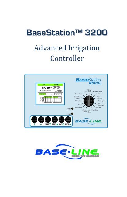
I n t r o d u c t i o niIntroductionSection Contents Controller Front Panel Layout ...............................................................................................5 Cabinet Options ....................................................................................................................6 Remote Communications Options (BaseManager) ...............................................................6 How to Irrigate Efficiently .....................................................................................................7Controller Front Panel LayoutA B CD E FUSB Port: The USB port is used for doing Backup and Restore operations using USBFlash Storage. It is also used for doing software upgrades and retrieving operation logfiles.Display: The TFT Color Display indicates the current state of the controller and is usedto display programming.Dial: The dial is used to select the operation or programming mode of the controller.Keys: The keys are used to select programming elements, change their values, andinitiate operations like testing a zone.Status LEDs: These two LEDs indicate the power status of the controller and theinternal status of the controller hardware.Remote Control Port: This connector is used with the BL Commander hand-held radioremote control to operate valves while away from the controller.Page 5<strong>Baseline</strong> <strong>3200</strong>
I n t r o d u c t i o nCabinet OptionsThe <strong>BaseStation</strong> <strong>3200</strong> is available in three basic cabinets:C-series: 16 gauge steel powder-coat indoor/outdoor wall mount cabinetX-series: 16 gauge galvanized steel powder-coat (X) or 16 gauge stainless steel (XS)indoor/outdoor large wall mount cabinetP-series: 16 gauge stainless steel pedestal cabinetC-series X/XS-series P-seriesAll cabinet dimensions are in inches (in).Remote Communications OptionsThe <strong>BaseStation</strong> <strong>3200</strong> is compatible with a number of remote communications options to enableremote access and Central Control using <strong>Baseline</strong>’s BaseManager system or BaseManager Webservice.BaseManager supports a variety of communications options. For installation instructions forremote communication devices, refer to the documentation included with the device.Page 6<strong>Baseline</strong> <strong>3200</strong>
I n t r o d u c t i o nHow to Irrigate EfficientlyThis section covers some key concepts essential to better and more efficient irrigation.The <strong>BaseStation</strong> <strong>3200</strong> is specifically designed to help you irrigate more efficiently than any othercommercial irrigation controller. The <strong>3200</strong> supports multiple smart watering strategies, includingHistorical ET, and smart watering with Soil Moisture Sensors.All other considerations being equal, Soil Moisture Sensors provide the best watering results ofany currently available technology. This is because the watering system can become “closedloop” – in other words, the system can directly measure and adjust for exactly what the desiredresult is: moisture in the root zone.Irrigating properly typically results in the elimination of water waste, and a subsequentimprovement in plant health.Water Deeply & Infrequently. Studies show that watering deeply and infrequentlypromotes deeper root growth and more drought tolerant plants.Watering Deeply means that the soil should be wetted down to a depth of 6”or deeper for grasses, 12” or deeper for trees and shrubs.Watering Infrequently means that the next irrigation event (or start time)should be delayed as long as possible without stressing the plants.Deeper Roots = More Efficient Plants. Plants with deeper roots are able to drawmore nutrients from a larger area of soil, making fertilizers and soil treatments moreeffective.Avoid Runoff. Matching the application rate of irrigation to the infiltration rate of thesoil is critical to avoid runoff.Only apply the amount of water needed. Optimum irrigation should account foractual effective rainfall, and avoid applying more water than required at the root zoneof the plantsIrrigation water is a supplement to natural rainfall – only the amount of waterneeded to return the soil to optimum moisture is needed.Irrigation water applied above the field capacity of the soil is wasted – waterwill gravitationally sink through the soil below the root zone of the plantsUnlike other irrigation controllers, the <strong>3200</strong> is specifically designed to make efficient irrigationeasy.To see how the <strong>BaseStation</strong> <strong>3200</strong> accomplishes this, there are several key concepts the irrigationprogrammer should understand:Soil Moisture ContentWatering StrategiesRoot Depth & Plant Water EfficiencySchedule GroupsDistribution UniformityThe remainder of this section covers these key concepts in more detail.Page 7<strong>Baseline</strong> <strong>3200</strong>
Drier WetterI n t r o d u c t i o nSoil Moisture ContentSoil scientists and Agronomists have been studying the plant-water-soil system for over 100years. Early work in irrigation efficiency focused on the estimation of soil moisture based onweather information, plant water requirements, and soil information such as soil texture andslope. With the availability of inexpensive and highly accurate soil moisture sensors, we are ableto take soil moisture based irrigation to a whole new level of efficiency and effectiveness.With soil moisture sensors, your controller can operate like a thermostat for your landscape –applying water when it is needed, and where it is needed.To understand soil moisture based smart irrigation, it is important to understand some industrystandard terms for soil moisture content:SaturationThe soil pores are filled with water and nearly all of theair in the soil has been displaced by water. Gravity willexert force on the water contained in saturated soils,moving it deeper into the ground (if possible). This isknown as “gravitational water”.Field CapacityMaximum AllowedDepletion (MAD)Permanent WiltPointOven DryThe level of soil moisture left in the soil after drainageof the gravitational water. Irrigation to levels abovefield capacity will result in runoff or drainage asgravitational water.Desired soil moisture deficit at the time of irrigation,typically set well above the wilt point.The minimal point of soil moisture where the plant(s)wilt and begin to die off.When soil is dried in an oven, nearly all water isremoved. This moisture content is used to provide areference for measuring saturation, field capacity, andMAD.One key point is that water applied above Field Capacity is generally wasted – it gravitationallymoves down through the soil and becomes unavailable to plants. Excess water will also leechnutrients from the soil into deeper soil layers, reducing the efficiency of fertilizers and soiltreatments.To understand field capacity, it is often useful to think of a sponge. If you dunk a sponge in abucket of water and pull it out, water will gravimetrically drain from the sponge for a period oftime. When this stops, the sponge will still be very wet, but will no longer be dripping. This isroughly equivalent to Field Capacity in soils – water is no longer draining into lower soil layersand is held in the root zone of the plants.Best plant health and plant water efficiency results are gained when soil moisture content ismaintained between Field Capacity and Maximum Allowed Depletion. Studies also show thatappropriately varying the time between irrigation events in order to allow the soil to dry to thechosen depletion point promotes deeper root growth and subsequently more efficiency anddrought tolerance from the plants.Page 8<strong>Baseline</strong> <strong>3200</strong>
I n t r o d u c t i o nWatering StrategiesEach property is unique, and has unique watering requirements. In order to support a broadrange of climate zones, plant types, landscape designs, and landscape usage requirements, the<strong>BaseStation</strong> <strong>3200</strong> supports a variety of watering strategies.The basic watering strategies supported by the <strong>3200</strong> are shown in the table below. Refer to theprogramming sections for details on how to configure your controller to use these strategies.TimedHistorical ETLower LimitLower LimitAutomaticUpper LimitUpper LimitAutomaticLike all irrigation controllers, the <strong>3200</strong> can be programmed to runzones on specific times and dates. Timed irrigation is the defaultsetting for any zone that has not been associated with a moisturesensor.The <strong>BaseStation</strong> <strong>3200</strong> allows the days between irrigation to be setaccording to a Historical ET calendar which, unlike typical seasonaladjustments, will promote deeper root growth and healthier plantsthroughout the season. However, Historical ET based watering willnot protect your landscape from unusual weather patterns in anygiven season.Also called Lower Threshold. In this soil moisture based smartwatering strategy, irrigation is suspended or skipped until the soildries to the lower limit, which may be set manually, or set using theautomatic calibration process. This watering strategy naturallywaters deeply and infrequently and promotes deeper root growth inplants. The controller will water for a specified run time each time itis allowed to water. Care should be taken to assure that ½” or moreof water is applied frequently enough to water sufficiently for thehottest period of the season.Lower Limit Automatic waters according to a lower limit strategy,but automatically performs a calibration cycle each month in orderto measure actual soil field capacity. This strategy is particularlyuseful for newly established landscapes where compaction andorganic development of soil can cause field capacity to varysignificantly over time.Also called Upper Threshold. In this soil moisture based smartwatering strategy, irrigation events are scheduled for specific timesand dates, but the total run time is adjusted by the controller tobring soil moisture up and very slightly over field capacity. Thiswatering strategy is particularly useful for landscapes that need tobe at a desired moisture level on a regular schedule, such as sportsfields or heavy use parks. On these types of properties, damage toturf takes place if the soil is either too wet or too dry.Upper Limit Automatic waters according to an upper limit strategy,but automatically performs a calibration cycle each month in orderto measure actual soil field capacity. This strategy is particularlyuseful for newly established landscapes where compaction andorganic development of soil can cause field capacity to varysignificantly over time.Page 9<strong>Baseline</strong> <strong>3200</strong>
I n t r o d u c t i o nOne important thing to remember about watering strategies: any one zone (or valve) can only bewatered according to one strategy. In other words, you cannot configure a zone to be wateredautomatically using a soil moisture sensor and also be watered on a separate timed schedule.Zones can be linked together and watered as a group, regardless of the watering strategyselected. See below for more information on Schedule Groups.Also note that, even with soil moisture based watering strategies, it is important to program thecontroller to be allowed to put down as much water as required to maintain plant health duringthe heat of the summer. The <strong>3200</strong> has built-in limits as to how much it is allowed to modify runtimes or watering days before it assumes that there is an equipment malfunction of some kind.One of the most common irrigation programming mistakes made is to apply too little waterduring the hottest days of the season. <strong>Baseline</strong> recommends that, regardless of water strategy,each Zone be programmed to water long enough to put down at least one-half inch (½”) of watereach time the controller is allowed to water. Set default run times that will apply ½” of water each time watering isscheduled for best results.Root Depth & Plant Water EfficiencyStudies show that most plants, including in particular standard turf grasses, do not grow deeperroots unless promoted to do so. While some turfgrass varietals more rapidly grow deeper rootstructures when properly watered, even Kentucky bluegrass will grow roots in excess of 12”when watered optimally and in appropriate soil textures.Watering deeply and infrequently on a consistent basis will promote healthier plants with deeperroot structures. As roots grow deeper, the plants are then able to access water in deeper andtypically wetter soil layers, making them even more water efficient. Plants with deeper roots arealso able to draw nutrients and fertilizers from deeper soil layers, making the plants morenutrition efficient as well. Watering deeply and infrequently will promote deeper root growth andhealthier plants.Zone Schedule GroupsMost landscapes are comprised of areas with different plant types and sun exposures. However,in most cases, these areas will be covered by multiple or even many valves or zones. In order toavoid the requirement of putting a soil moisture sensor in every single zone, the <strong>BaseStation</strong><strong>3200</strong> allows users to group zones into a Schedule Group. Each Schedule Group has a PrimaryZone, which can be watered according to any of the Watering Strategies outlined above, and anynumber of Linked Zones, which will be watered on the same basic schedule as the Primary Zone.Schedule Groups are typically used to group zones in a Hydrozone together so that they can bewatered similarly. A Hydrozone is defined in the landscape industry as any group of zones thathave similar plant types and watering requirements.Example: A sports park has four baseball fields and four soccer fields in addition to someperimeter and parking lot shrub areas.Since it is desired that the infield areas of the baseball fields will be watereddifferently from the outfields, the infields of all four baseball diamonds are grouped asPage 10<strong>Baseline</strong> <strong>3200</strong>
I n t r o d u c t i o none Schedule Group, and are controlled by a single soil moisture sensor in one of theinfields.Likewise, all zones covering the outfields are grouped into a second Schedule Groupcontrolled by a single moisture sensor in one of the outfields.Since all the soccer fields have similar plant types and sun exposures, all zones for allthe soccer fields are grouped together and controlled from a single soil moisturesensor located in one of the fields.Lastly, the parking lot and perimeter shrub beds are broken into two schedule groupsrepresenting sunny and shady exposures, and are placed into two Schedule Groups.In this way, 42 individual zones are configured into 5 Schedule Groups controlled by 5moisture sensors.In the example above, all 5 Schedule Groups are each watered using a soil moisture sensor, andwould be configured to an Upper or Lower Limit watering strategy as outlined earlier. However,this is not required – each Schedule Group can be watered according to any watering strategyappropriate to that section of the landscape.One additional benefit of grouping Zones into Schedule Groups is for ease of adjustments. Byadjusting the programming of the Primary Zone, the programming of all Linked Zones willautomatically be adjusted.Soak CyclingWhen irrigating, it is important to understand the difference between the rate at which theirrigation application devices, such as spray heads, impact heads, rotor heads, multi-streamrotors, drip emitters, subsurface drip tubing, etc., apply water may be very different than therate at which the soil in your landscape can take up that water.Precipitation Rates vs. Infiltration RatesPrecipitation Rates, or the rate at which sprinkler heads or drip emitters apply water to the soil,are typically measured in inches, like rainfall.Many soils only allow water infiltration at a rate of .25” per hour or less, whereas most headtypes put down .50” per hour or more (much more in the case of some spray heads).It is also important to remember that head spacing and overlap directly influence the totalprecipitation rate for any specific zone.Precipitation Rates for Common Sprinkler Types:Spray Heads1.00” to greater than 5.00” per hourGear Driven Rotors 0.25” to 0.65” per hourMulti-stream Rotors 0.40” to 0.60” per hourDrip EmittersDepends on area covered, rarely exceeds infiltration rateEstimated Infiltration Rates for Common Soil Types:Course Sand:0.75” to 1.00” per hourFine Sand:0.50” to 0.75” per hourFind Sandy Loam: 0.35” to 0.50” per hourSilt Loam:0.15” to 0.40” per hourClay Loam:0.10” to 0.20” per hourPage 11<strong>Baseline</strong> <strong>3200</strong>
I n t r o d u c t i o nAs you can see from the tables above, most sprinkler heads have higher precipitation rates thanmost soils. Soak Cycling breaks the total run time into shorter water “cycles” with“soak” periods in between to allow time for water to soak into the soil.When the irrigation schedule puts down more water than the soil can take up, the excess waterwill typically run off to the lowest point, leaving some areas of the landscape, or even the entireirrigated landscape, under watered. Standing water also evaporates at a fairly high rate,especially in the heat of the summer months, further reducing irrigation efficiency.Even on a perfectly designed system, it is important to match the water application rate to theinfiltration rate of your soil. This is typically accomplished by breaking a total run-time for anyZone into multiple “cycles” (timed water applications) and “soaks” (timed wait periods for thewater applied in the last cycle to infiltrate into the soil before applying more water).The <strong>BaseStation</strong> <strong>3200</strong> has built-in support for soak cycling, and has intelligent wateringalgorithms that apply cycles in the optimal order to maximize water penetration and minimizeevaporation loss. Soak Cycling is required on all soil moisture based Zones or ScheduleGroups in order to insure that the applied irrigation water is penetratingappropriately to the moisture sensor.<strong>Baseline</strong> recommends as a rule-of-thumb that the total run time for any zone be broken into atleast 3 cycles, and that the soak time between cycles be at least twice the length of the cycletime. One easy way to determine good cycle times is to turn a zone on andwatch for first signs of standing water or runoff. Set the cycle time to beno more than this amount of time.Properly setting soak and cycle times will dramatically improve water penetration and wateringefficiency.Distribution UniformityDistribution Uniformity (DU) refers to how evenly water is applied over the area in a particularzone or landscape. This is generally driven by the choice of heads (spray, rotor, multi-stream,etc.) and the irrigation design.Sadly, it is very common that distribution uniformity is fairly low in real-world irrigatedlandscapes. This is due to many factors beyond the scope of this manual, but it is important tonote that system problems such as uneven coverage will limit the effectiveness of smartwatering strategies.<strong>Baseline</strong>’s experience is that high-uniformity systems can be built from nearly any head type, aslong as it is properly designed, installed and maintained. The <strong>BaseStation</strong> <strong>3200</strong> controller can compensate for but cannot solvedistribution uniformity problems.As you intelligently reduce water applied to any zone, you may notice stressed areas or “brownspots” in your landscape. When this happens, you should first adjust your heads to makecoverage as even as possible. In extreme cases it may be advantageous to retrofit older headswith new types of heads such as multi-stream rotors that apply water more evenly.Page 12<strong>Baseline</strong> <strong>3200</strong>
I n t r o d u c t i o n If you do get brown spots in your landscape, fixing distribution uniformityissues will give better long term results than increasing run times ormoisture settings.Every irrigation controller must be programmed to water to the “driest spot” in each zone. If thedifference between water applied at the driest spot is too great (especially if the wettest spothas more than 3 times the water applied in the same period as to the dries spot) then you shouldtake steps to adjust your heads, their spacing, and their coverage to gain better uniformity.You can quickly and easily measure the distribution uniformity of your landscape by placing catchcups in any particular zone and then running that zone for a specific period of time. Auditingzones in this manner will also give you very exact information about how much water is appliedper hour in that zone, which makes setting default run-times easy. <strong>Baseline</strong> highly recommendsthat you audit zones in order to determine uniformity and actual application rates.Page 13<strong>Baseline</strong> <strong>3200</strong>
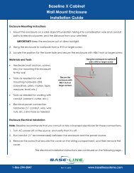
C h a p t e r 1 – G e t t i n g S t a r t e d1 Getting StartedSection Contents Installing the <strong>BaseStation</strong> <strong>3200</strong> .......................................................................................... 14 Installing Standard Accessories .......................................................................................... 17 Conventional Irrigation Wiring Installation......................................................................... 18 Two-wire Installation .......................................................................................................... 20 Searching for and Assigning Valves .................................................................................... 26 BL-Commander ................................................................................................................... 34Installing the <strong>BaseStation</strong> <strong>3200</strong>This section covers the basic installation of the various <strong>3200</strong> controllers.C-series Wall Mount CabinetsThe C-series Wall Mount cabinet is designed for outdoor or indoor wall or pole mounting. Thecabinet features four screw or bolt mounting holes on tabs above and below the controllerchassis as shown below:Mounting HolesThe screw holes are approximately 1/4” x 1/3”, and are located3” apart.For exterior and especially for pole or post mountedapplications, care should be taken to avoid direct spray fromsprinkler heads or other water sources.For detailed dimensions andinstallation drawings, please visitthe documentation library on the<strong>Baseline</strong> web site.Connecting power & groundAll C-series Wall Mount <strong>3200</strong> controller ship with a conduit ready ½”male exposed thread connection point as shown in the diagram:AC power connections should be made in an approved electricalconnection junction box, and in accordance with all localelectrical codes.Wire nuts for AC power connections are provided.110VAC Conduit connection(240VAC for –INT units)Page 14<strong>Baseline</strong> <strong>3200</strong>
C h a p t e r 1 – G e t t i n g S t a r t e dX/XS-series Wall Mount CabinetsThe X and XS series Wall Mount cabinets are designed for outdoor or indoor wall or postmounting. The cabinet features a center located key-hole main mounting screw assembly foreasy mounting, plus an additional center mounted hole as indicated in the diagram below. The X& XS cabinets feature a ¼” air gap between the chassis and the mounting surface – this reduceslong term risk of water incursion or ice-dam buildup during inclement weather.For security purposes, all mounting screw heads are protected behind the locked front cover,making theft or vandalism materially more difficult.Post or pole mounted units should use an appropriate wood or metal back-plate behind thecabinet to insure best long term reliability and secure connections.Keyhole Mount#10 Pan Head ScrewStandoffsThrough-hole Mount#10 Pan Head ScrewSide ViewRear ViewConnecting power & groundMain AC Power connection is via a small built-in electrical box in the lower left of the enclosure.Remove the screw on the right and the access panel to access the box. The box has a knock outsuitable for direct connection of a ½” conduit.Front View24VAC TransformerIntegrated Electrical Box (remove screw and panel to access)110VAC Power & Ground Wires (240VAC for –INT units)Wire nuts included.Case Ground LugRemote Connection Modules and AntennasAll installations should comply with local and nationalelectrical codesIf installed, antennas for WiFi, Cell Modem, and Mesh Radio communication units mount throughthe top mounted access port. BL Commander permanent receiver unit antennas mount on theright access port (typically factory installed). To install a communications module in an existingcabinet, consult the documentation that came with the communications module.Page 15<strong>Baseline</strong> <strong>3200</strong>
C h a p t e r 1 – G e t t i n g S t a r t e dP-series Pedestals CabinetsThe P-series Pedestal units are designed to be pad-mounted, and come with a concrete templatefor locating all mounting bolts, AC power and two-wire and/or valve wire conduits.Locking Top CoverFront PanelFan AssemblyControl Board (R-series shows)24VAC TransformerAccessory Outlet (GFIC)Mounting BoltsGrade LevelPower ConduitAC surge protectionKeyed Power SwitchAC Power Junction BoxChassis Ground LugCement PadValve & Two-Wire ConduitMounting pedestal to concrete platformAll P-series Pedestal units are shipped with a metal form to locate mounting bolts and conduits.The concrete pad should be installed to <strong>Baseline</strong> specifications with proper slope for drainage.Consult the Documentation Library on the <strong>Baseline</strong> web site at http://www.baselinesystems.comfor CAD details and additional instructions.Remote Connection Modules and AntennasIf installed, antennas for WiFi, Cell Modem, and Mesh Radio communication units mount throughthe access port on the left side of the pedestal, and include a stainless steel mounting body toprotect antenna cabling and raise antennas above the top of the pedestal for best signalstrength. Consult the Documentation Library on the <strong>Baseline</strong> web site athttp://www.baselinesystems.com for CAD details, communications options, and internallocations for communications modules.If equipped with a permanent mounted BL Commander handheld remote control receiver kit, thereceiver antenna will be mounted on the upper right side of the Pedestal enclosure.Page 16<strong>Baseline</strong> <strong>3200</strong>
C h a p t e r 1 – G e t t i n g S t a r t e dInstalling Standard AccessoriesRain Switches and other Normally Closed Sensing DevicesAll <strong>BaseStation</strong> <strong>3200</strong> controllers are compatible with industry standard Normally Closed (NC)sensing devices such as rain switches. These devices can be directly connected to theappropriate terminals on the <strong>3200</strong>, or can be connected using Pause biCoders to the two-wirepath. The pause behavior of the unit, and the associated messages and alerts generated, will bedifferent if the NC device is connected to a Pause biCoder than if it is directly connected to asensor terminal on the <strong>3200</strong>. Normally Closed sensing devices, such as a rain switch, that are directlyconnected to the <strong>3200</strong> cannot be overridden. Watering will be stopped forall programs until the switch re-connects (i.e., the rain switch dries out.)Pause devices including rain switches can be connected to Pause biCoders,which can be associated with (or ignored by) specific programs. See theappropriate programming section below for more details.Connecting a Rain Switch to the <strong>BaseStation</strong> <strong>3200</strong>Normally Closed RainSwitchPAUSE |RAIN |FLOW |COM BLACK RED BLACK RED| AC+ | AC- | PAUSE |RAIN |FLOW |COM BLACK RED BLACK REDStandard <strong>3200</strong> Connection ModuleSpecific watering behavior is different for each of the different ports:Rain Sensor Port: on activation, all watering is stopped, and all active programs are terminated.No new irrigation will be allowed to start until the rain switch deactivates (dries out). <strong>Baseline</strong>recommends that rain switches connected this way are set to the shortest possible delay setting.Smart irrigation using soil moisture sensors will automatically account for all rainfall whichpenetrates into the soil, which is often quite different that the amount of total rainfall asmeasured by a rain switch.Flow Sensor Port: on activation, all watering is stopped, and all active programs are terminated.No new irrigation will be allowed to start until (1) the flow sensor input is cleared (no longeropen), and (2) the flow alert is cleared in the controller. The flow alert can be cleared remotelyusing BaseManager central control, but requires user intervention. <strong>Manual</strong> intervention isrequired to protect against landscape damage caused by broken pipes or valves.Pause Port: on each activation (open circuit), all irrigation will temporarily be paused for 4 hours.All active programs and scheduled watering will resume after the pause period has ended. If thepause port is activated again during the pause period, the 4 hour pause period will be restarted.Page 17<strong>Baseline</strong> <strong>3200</strong>
A1 2 3 4 5 6 7 8 9 10 11 12 B1 2 3 4 5 6 7 8 9 10 11 12C h a p t e r 1 – G e t t i n g S t a r t e d Normally Closed sensing devices should not be wired in series with eitherthe valve common (on R-series units) or either side of the two-wire path.Wiring devices in this manner will defeat the wire health and solenoidcurrent detection features built into the controller, and will generateincorrect messages and alerts. It is recommended that all Normally Closedsensing devices be connected to the appropriate terminal on thecontroller, or to a Pause biCoder connected to the two-wire path.Wireless Rain SensorsAnother popular accessory is a wireless rain sensor. Wireless sensors are different than standardrain sensors because they require external power, typically 24VAC.Different wireless rain sensors have different receiver wiring requirements. Consult the usermanual with your wireless rain sensor forConventional Irrigation Wiring Installation<strong>BaseStation</strong> <strong>3200</strong>R controllers and <strong>Baseline</strong> 5200R series powered biCoders connect directly toconventional 24V AC irrigation wiring, with one wire for each valve plus a common wire.Additionally, these devices are capable of communicating to soil moisture sensors over specificterminals that are enabled to search for and communicate with <strong>Baseline</strong> biSensors.Conventional Wiring ModulesEach <strong>3200</strong>R controller can be equipped with 12, 24, 36, or 48zones, depending on the cabinet.One 12 or 24 zone connection module will fit in a C-seriescabinet, and two 12 or 24 zone connection modules can beequipped in an X, XS or P cabinet.The terminal designations for each 12 or 24 zone connectionmodule are shown in the diagram on the left, and include: Rain Sensor Port (Normally Closed) Two-wire Port (Red & Black) Valve Common (x2) Master Valve/Pump Start terminals (2, designated VE1and VE2) – these may also be re-addressed to controlconventional zones if desired. Sensor-over-valve-wire Ports (x2 for 12 zone, x4 for 24zone) each with a status LED. Standard valve wire ports (x10 for 12 zone, x20 for 24zone).Only two zones of any 12 zone block of terminals can beactivated concurrently, plus VE1 and VE2, resulting in a totalconcurrency of 6 zones for a 24 zone unit.<strong>Baseline</strong> biSensors can be connected directly to valve wires onthe Sensor-over-valve-wire ports (A1, A2 and B1, B2).Wiring examples are shown in the section below.Rain SensorTwo-wire: Black/RedValve COMMONVE----1 & VE----2Read biSensorsbiSensor ConnectionbiSensor ConnectionbiSensor ConnectionbiSensor ConnectionPage 18<strong>Baseline</strong> <strong>3200</strong>
C h a p t e r 1 – G e t t i n g S t a r t e dConnecting Valve Wires and Moisture Sensors over Valve Wires<strong>Baseline</strong> biSensors can be connected directly to the valve wires on the Sensor-over-valve-wirePorts (A1, A2, B1, B2) on any 12 or 24 zone connection module:Conventional Wiring Example with one biSensor:<strong>Baseline</strong> biSensorconnected over valvewires. Note waterproofconnectorsExisting valve andcommon wires used.Expanding with Two-wireAll <strong>BaseStation</strong> <strong>3200</strong> controllers are capable of communicating with <strong>Baseline</strong> biCoders andbiSensors connected to a two-wire path. Any supported two-wire devices may be connected:<strong>Baseline</strong> biSensorconnected over valvewiresExpansion using twowire,including fieldbiCoder and biSensorAll wire connectionsshould be water-proof!Page 19<strong>Baseline</strong> <strong>3200</strong>
C h a p t e r 1 – G e t t i n g S t a r t e dTwo-wire InstallationAll <strong>BaseStation</strong> <strong>3200</strong> and <strong>3200</strong>R controllers are equipped with a full-function two-wire portcapable of connecting to field biCoders, powered retrofit biCoders, biSensors, flow meters, andother devices. Since <strong>Baseline</strong>’s two-wire features full bidirectional communications, you canconnect all your irrigation accessories to the same two-wire path – saving time and moneycompared to conventional wiring.The <strong>BaseStation</strong> <strong>3200</strong> can communicate with all of the following <strong>Baseline</strong> accessories:One, two and four valve biCoder field decoders12, 24, 36, and 48 zone 5200R series powered retrofit biCodersbiSensor Soil Moisture SensorsPFS Series Smart PVC Flow SensorsBFM Series Smart Metal-body Flow MetersBHM Series Hydrometers – Metal-body Flow Meter and Master Valve combinationFlow Sensor biCoders for connection to 3 rd party flow sensors and master valvesPause biCoder – compatible with any standard Normally Closed pause device such asa rain switch, wind switch, etc.Air Temperature biCoderPause Button (a.k.a. “Coach’s Button”)Pump Relay biCoderLightning Arrestor/Surge Suppression devicesEvery <strong>BaseStation</strong> <strong>3200</strong> can be expanded to support up to 200 zones using virtually anycombination of two-wire and conventional wiring.Two-wire Serial NumbersEach <strong>Baseline</strong> two-wire device has a unique serial number used to identify it. Serial numbers arelabeled on all <strong>Baseline</strong> devices. For devices such as two or four zone biCoders, each output forthe biCoder has a unique serial number, even if it only has one serial number listed on its label.See the diagram below:Serial Numbers for Four-zone biCoder<strong>BaseStation</strong> <strong>3200</strong>R systems have built-in decoders, and each screw terminal has a unique serialnumber. These serial numbers are listed on the wiring label that is included in the unit as shownin the picture below.Page 20<strong>Baseline</strong> <strong>3200</strong>
C h a p t e r 1 – G e t t i n g S t a r t e dSerial Numbers for zones 1-24 in a <strong>BaseStation</strong> <strong>3200</strong>R<strong>BaseStation</strong> <strong>3200</strong>R systems are preconfigured at the factory to assign zones 1 to 48 (dependingon how many zones the unit is equipped with) to terminals 1 through 48. However, by using thespecific serial number, any terminal can be re-mapped to any zone address.Two-wire Connections and Layout<strong>Baseline</strong> uses a proprietary digital protocol to communicate over two-wire. For a complete andmost up-to-date two-wire specification, please refer to the Documentation Library on the<strong>Baseline</strong> web site. Below is a summary of the <strong>Baseline</strong> two-wire Specifications:Wire Type Only polyethylene double-jacketed or UF-B UL PVC double-jacketed two-conductorsolid core designed for direct burial systems will be supported. All wire insulation shall be intact and free of nicks and cuts. The conductors shall be soft drawn, annealed, solid copper conforming to ASTM 33(tinned or non-tinned). Conductor insulation shall be 4/64-inch thick polyvinyl chloride (PVC) or polyethylene,conforming to UL Standard #493 for thermoplastic-insulated style UF (UndergroundFeeder), rated at 60 degrees C. The two insulated conductors are laid in parallel and encased in a single outer jacketof 3/64-inch thick, high density, sunlight resistant polyethylene conforming to ICEA S-61-402 and NEMA WC5, having a minimum wall thickness of .045-inch. The two conductors shall be color-coded: normally one conductor red and one black. Both conductors shall be the same size. The following is a sample of approved manufacturers and part numbers: Coleman Cable #51452 Paige P7072D-Rev 12, P7296D, P7295D, P7350D and P7354D Regency 14/2 and 12/2, “Maxi Cable” or “UF-B”Wire ConnectionsAll wire connections should be fully waterproof, and installed in compliance with the connectormanufacturer’s instructions. All two-wire connections should be water-proof, using a water proofconnector conforming to the <strong>Baseline</strong> specification. All connectors shouldbe 3M DBR-6 or 3M DBR/Y equivalent.Strain relief of 24 to 36 inches is recommended at each wire connection to make valve boxinstallation and troubleshooting easier, and to provide protection against thermal expansionpulling connections apart on long wire runs.Page 21<strong>Baseline</strong> <strong>3200</strong>
C h a p t e r 1 – G e t t i n g S t a r t e dWire LengthsTotal wire length supported depends on the gauge of the wire used.Straight RunLooped RunWire LayoutStraight line, star, looped and combination configurations are supported (see next page fordiagrams).It is suggested that only one continuous loop be laid out around the site. This usually follows themain water lines. The loop will start at the <strong>BaseStation</strong> Controller, continue around the site andthen return to the controller. This provides the best communication and power path for thesystem. This loop provides a redundant path for the power and signal allowing the system tocontinue operation if the loop is cut.Straight LineLoopedCombinationStarPage 22<strong>Baseline</strong> <strong>3200</strong>
C h a p t e r 1 – G e t t i n g S t a r t e dWire BurialWire should be buried at a depth appropriate to protect the wire from mechanical damage dueto digging or aeration.<strong>Baseline</strong>’s two-wire system operates under 30VAC RMS, which is considered safe for shallowburial as outlined in the National Electric Code. All installations should comply with localelectrical codes.Field Decoder Wiring<strong>Baseline</strong> field biCoders are deisgned fordirect burial and are tested to very rigorousstandards of durability.All connections in valve boxes must be fullywaterproof. The connectors on the twowirepath must conform to 3M DBR-6 or 3MDBR/Y specifications and be properlyinstalled. Connectors on the valve sidemust conform to 3M DBY specifications.BiCoders include status and activity LEDs fortroubleshooting purposes. The biCodersshould be installed such that LEDs arevisible when the valve box is open.Valve side wire may be extended up to 100feet, allowing one decoder to control valvesin multiple valve boxes.Surge ProtectionLightning Arrestors should be installedaccording to the specification below, and ingeneral every 600 feet along the wire path.Each Lightning Arrestor will protect roughly a 300 foot circle and should be grounded using anappropriate ground rod or plate as per the <strong>Baseline</strong> BL-LA01 Surge Arrestor Specification.Page 23<strong>Baseline</strong> <strong>3200</strong>
C h a p t e r 1 – G e t t i n g S t a r t e dFor R-series controllers, a lightning arrestor and appropriate ground rod or plate are required foreach moisture sensor connected to a valve wire that is more than 300’ from the controller.Connecting to BL-5200R Series Wall Mount biCoders<strong>Baseline</strong> 5200R series powered biCoders are specifically intended for retrofit applications, andmake combining several old controllers into a single <strong>BaseStation</strong> <strong>3200</strong> easy and affordable.BL-5200X-R48 – 48 Zone Wall Mount biCoder in X-Series Cabinet5200R series biCoders require 110VAC power (240VAC for –INT versions), and are available in C-series and X/XS-series wall mount cabinets, or P-series pedestals.Example Wiring Diagram<strong>BaseStation</strong> <strong>3200</strong>RBL-5200C-R24Two-wire PathbiSensorField biCodersUp to 20 5200R series biCoders can be connected to a single <strong>BaseStation</strong> <strong>3200</strong>, allowing a largesite with multiple controllers to be cost effectively retrofitted with a single <strong>BaseStation</strong> <strong>3200</strong> unit.Page 24<strong>Baseline</strong> <strong>3200</strong>
C h a p t e r 1 – G e t t i n g S t a r t e dTotal Supported Devices & LimitsListed below are the total numbers of devices by type that can be connected to a <strong>BaseStation</strong><strong>3200</strong>. The <strong>BaseStation</strong> <strong>3200</strong> can communicate with a maximum of 110 devices (device loads) onthe two-wire path within the layout and length limits outlined later in this section.Two-Wire Device Type Total Device LoadsField (Valve) biCoders 200 1 per biCoder5200R series biCoders 20 2 per biCoderbiSensors 25 1Master Valves/Pump Starts 4 1Flow Meters 4 3Pause Devices 4 1Up to 110 total device loads are supported, and only 200 zones may be configured in the <strong>3200</strong> or<strong>3200</strong>R controller.Unused ports or serial numbers on biCoders do not occupy a zone address and do not counttowards the 200 zone limit.Maximum Concurrent ValvesThe maximum number of concurrently operating valves is shown in the two tables below, andvaries based on the total load count and wire length to the farthest device:Maximum Wire Distances for <strong>3200</strong>R and 5200R series biCodersPage 25<strong>Baseline</strong> <strong>3200</strong>
C h a p t e r 1 – G e t t i n g S t a r t e dInstalling biSensor Soil Moisture SensorsIn order to locate a good place for a biSensor, you must first choose which zone or zones sensorsshould be installed in. To do this requires that zones be grouped into Schedule Groups. Only onezone in a Schedule Group will have a sensor, which will make it the Primary Zone. Within thisPrimary Zone, you can then choose a good location for the sensor.Grouping Zones into Schedule Groups (or Hydrozones)A Schedule Group is a group of zones that have been linked together such that they can all becontrolled with a single watering strategy, typically with a single biSensor.A Schedule Group can be made of any zones that:Require irrigation on the same frequency (i.e., same days)Have similar plant types (turf, shrubs, etc.)Do not have excessive difference in sun or wind exposureAre irrigated with similar water application technologies. Assuming zones meet thecriteria above:Spray, rotor & multi-stream zones can be combined, as long as there is not a 10x orgreater difference in application ratesDrip zones can be combinedSubsurface drip zones can be combinedEach Schedule Group has a Primary Zone (where the moisture sensor is located if one is to beused), and any number of Linked Zones.Each Linked Zone will be watered on the same schedule as the Primary Zone, but the specificwater time for each Linked Zone may be individually adjusted in comparison to the Primary Zone.Choosing the Primary Zone for a Schedule GroupSince zones in a Schedule Group are naturally similar, most zones in any group can make a goodPrimary Zone. For larger Schedule Groups, or Schedule Groups with a higher level of variation insun or wind exposure, choose a Primary Zone that:Requires irrigation the most frequentlyHas an average or greater sun and wind exposure for the Schedule GroupOne important note: in order to simplify programming, the <strong>3200</strong> requires that the zone numberfor any Primary Zone be lower than the other Linked Zones in a Schedule Group. For retrofits,this may occasionally require that you renumber your zones.Choosing the Sensor LocationBest Results are achieved when the biSensor is located in an area that is average for the zone,and ideally for the entire Schedule Group. For optimal results, the following should be avoided:Drainage areas where irrigation or rainwater pools or is channeledAreas immediately around hardscapes or that receive runoff water from hardscapesor buildings.As long as the location of the sensor is average for the zone, excellent water efficiency can beachieved.Page 26<strong>Baseline</strong> <strong>3200</strong>
C h a p t e r 1 – G e t t i n g S t a r t e dDealing with Slopes and BermsSteep slopes and berms are possibly the most difficult landscape areas to irrigate efficiently.Runoff is the main issue, but there are also often subsurface drainage issues that can result insoaking wet low areas and bone dry high areas. Construction of berms often requirescompaction of the central mass, which can also cause water movement and drainage issues.Soil Moisture Sensors can be an excellent tool to optimize watering for slopes and berms, sincethe sensor can detect how much irrigation water is actually infiltrating the upper levels of theslope or berm.Particular care must be taken to set proper soak and cycle times for slopes and berms – someslopes can require that total run time is broken into 5 or more cycles.Top 1/3 of the slope, andnot at the crownIn the top 1/3 of the rootzone (2-3” for turf grass)Not sideways to theslope.Optimal biSensor Placement for Slopes and BermsIf the slope or berm is irrigated as a part of a larger zone that is mostly level, then it isrecommended that the sensor is placed in the larger level area. However, for most efficientresults, slopes and berms should generally be broken into separate zones.Burying the biSensorThe biSensor should be installed in accordance with the installation instructions included with it.When installing a biSensor in an established landscape, care should be taken to disturb thesurrounding soil as little as possible – this reduces the chance that adjustments will be neededlater.In general, biSensors should be installed in the top 1/3 of the root zone for the plant that is beingirrigated. In the case of turfgrass, the top of the sensor blade should be 2” to 3” from the bottomof the thatch layer. Burying the moisture sensor too deep can cause poor results. If the sensoris deeper than the top 1/3 of the root zone, these roots can become toodry and the plants may become stressed.Page 27<strong>Baseline</strong> <strong>3200</strong>
C h a p t e r 1 – G e t t i n g S t a r t e dTurfgrassAs stated above, the sensor should be buried 2” to 3” to the top of the blade, or in the top 1/3 ofthe root zone of the grass:Newly Seeded Turfgrass or New SodThe default watering strategies for the <strong>3200</strong> are intended to optimize water efficiency forestablished plants and turf. This style of watering can result in poor performance for newlyseeded turf.In the case of newly seeded turf grass, sensors should be installed in accordance with theinstructions and at the proper depth. However, watering should be applied according to anappropriate timed schedule until the grass has rooted sufficiently (typically 60 to 90 days) beforeenabling a sensor based watering strategy. Once the grass has rooted, the Primary Zone can beconverted to a sensor based watering strategy.Likewise, newly installed sod has very shallow roots. New sod should be watered on anappropriate time schedule until it has rooted sufficiently to enable a sensor based wateringstrategy (typically 30 to 60 days).Trees and ShrubsIf trees and shrubs are watered separately, a moisture sensor is an excellent tool to maintainhealth and beauty of trees and shrubs. Typically, multiple trees are watered by the same zone. Ifso, choose an average tree, and install the biSensor in the top 1/3 of the root zone of the tree.Angling the sensor willaverage readings acrossgreater depth if needed.Top 1/3 of the root zonebiSensor in the top 1/3 of the root zone of an established treePage 28<strong>Baseline</strong> <strong>3200</strong>
C h a p t e r 1 – G e t t i n g S t a r t e dAngling the sensor can profile a deeper soil column for trees that have deeper root structures aswell.If the tree is watered with drip emitters or bubblers, install the sensor in a location that is notdirectly under the emitter or bubbler to avoid partial watering of the whole root zone of the tree.If multiple emitters are used for a single tree, a good rule of thumb is to install the sensor roughlyhalf way between two emitters and as much inside the root mass of the tree as possible withoutdamaging the roots. Root depth and water requirements for trees and shrubs vary much moregreatly than for turf. Consult an experienced Arborist for or MasterGardener for specific guidelines for watering trees.Most trees are watered along with turf in commercial landscapes. In this case, <strong>Baseline</strong>recommends that biSensor(s) be installed for the turf areas, and that the default run time(s) ofzones with trees be adjusted to insure water application to 12” or whatever is required tooptimize tree health.Installing biSensors with New TreesIn the case of new landscape with newly installed trees that are watered separately from turfzones, it is important to make sure that the sensor is located as close to the root ball in the top1/3 of the root ball as possible. Watering new trees with a sensor based watering strategy is agood way of avoiding inadvertently “drowning” new trees and shrubs due to overwatering.Shrubs and Other Ornamental PlantsMany landscapes feature shrub zones that are separately watered from turf zones. Shrubsgenerally have very different water needs from turf, so this is a good thing!For shrub zones, a representative plant should be chosen, and the biSensor should be installed inor close to the top 1/3 of the root zone for the plant, without damaging the root structure of theplant.If drip emitters or bubblers are used, install the sensor in a location that is not directly under theemitter or bubbler to avoid partial watering of the whole root zone of the plant.Gardens and Crop PlantsSensors are excellent tools for maximizing crop results, and have been used for decades inirrigated agriculture.Garden and crop plant watering depends greatly on the type of plants being grown, and isbeyond the scope of this manual.To plan a watering strategy for larger gardens or crops, <strong>Baseline</strong> recommends that you contactyour local Cooperative Extension Office. You can find a national register of the extension officesat: http://www.csrees.usda.gov/Extension/.Page 29<strong>Baseline</strong> <strong>3200</strong>
C h a p t e r 1 – G e t t i n g S t a r t e dSearching for and Assigning DevicesBefore any biCoders or biSensors can be programmed in the controller, the controller must findthat device and assign it as appropriate. There are different types of biCoders and other twowiredevices that can be connected directly to the <strong>3200</strong> two wire path, including:Valve biCoders (decoders)biSensors (soil moisture sensors)Pause biCodersAir Temperature SensorFlow Meters & Flow SensorsPause ButtonThe <strong>3200</strong> is capable of searching for all devices connected to the two-wire path, and reportingthese devices back to the controller. However, before they can be used, they must be “assigned”to an appropriate use.Searches for different types of biCoders are accomplished in different dial positions as outlined inthe sections below.Zone Numbers vs. Serial NumbersThe <strong>BaseStation</strong> <strong>3200</strong> controller can be attached to valves, master valves and pump start deviceseither with a screw terminal (for “R” series conventionally wired systems and 5200R seriespowered biCoders) or via an output wire on a two-wire biCoder.In the <strong>3200</strong>, any valve biCoder serial number can be mapped or assigned to any zone number. <strong>BaseStation</strong> <strong>3200</strong>R conventionally wired controllers are pre-programmedat the factory such that zones 1 up to 48 (depending on the specificconfiguration purchased) will already be assigned to terminals 1 to 48 tomake installation quick and easy.For field biCoders, or for 5200R series wall mount biCoders, you must search for and then assigneach serial number you wish to use to a zone number or master valve.You may also wish to reassign and/or reorder certain zones in order to properly combine Primaryand Linked zones in a Scheduling Group.The <strong>3200</strong> makes these assignments quick and easy to do, but care should be taken to documentchanges made to the system. Failure to properly document assignments can cause confusionand frustration for maintenance staff.Assigning Valve biCoders to Zone NumbersThe <strong>3200</strong> controller is capable of mapping any valve biCoder serial number to any zone Number. Any valve terminal (in R-series controllers or 5200R biCoders) and anyoutput on any field biCoder can be assigned to any unique zone address.Care should be taken to document addressing changes, since it can beconfusing for maintenance personnel when terminal #1, for example, isassigned to a different zone number.Page 30<strong>Baseline</strong> <strong>3200</strong>
C h a p t e r 1 – G e t t i n g S t a r t e dStep 1: Search for biCodersValve biCoder assignment is accomplished inthe biCoder Menu dial position.Turn the dial to the biCoder Menu, then pressENTR to Search for biCoders.Like all menus on the <strong>3200</strong>, you can look atthe on-screen help for instructions.The Search may take several minutes to complete. Youwill see a status screen like the one shown here whilethe search is in progress.Press CLR to cancel a search in progress.Step 2: Assign biCoder(s) to ZonesUse the +/- keys to select any unassignedbiCoder serial number.Use the NEXT/PREV keys to select anavailable Zone Number.Press ENTR to Assign the selected biCoder tothat Zone Number.Master Valves MV1-MV4 are assigned thissame way, and can be assigned to any singleor two valve biCoder.CLEAR Function – clear a previous zonenumber assignment.To clear a biCoder serial number previouslyassigned to a Zone Number, use NEXT/PREVto highlight that Zone Number, then use the+/- keys to select “Clear”, then press ENTR.In the Zone Number list, Zones that havebeen set to be Primary Zones will have a “P”next to them.Page 31<strong>Baseline</strong> <strong>3200</strong>
C h a p t e r 1 – G e t t i n g S t a r t e dZone StatusNote that the status of each zone is shown inthe Zone Number list. The zone status codesare:OK – Working properlyOP – Open circuitSC – Short circuitER – Communication errorZone Numbers are Pre-Assigned in R-seriesAll conventional wire versions (R-series) of the <strong>3200</strong> have been pre-assigned at the factory suchthat terminal 1 is assigned to zone 1, terminal 2 is assigned to zone 2, etc. However, you canchange these zone numbers to organize Scheduling Groups, Primary and Linked zones to achieveoptimal watering behavior.To change or re-order zone numbers in an R-series unit, use the CLEAR function as outlinedabove, and then Assign each biCoder serial number to the desired Zone Number.The serial numbers for all terminals in <strong>3200</strong>R controllers are shown on the label next to theterminals. The serial numbers for terminals in 5200R biCoders are shown on the door label.Assigning Other DevicesAir Temperature SensorsAn Air Temperature Sensor does not need to be assignedto any address, but it must be found by the controller.To search for an air temperature sensor, turn the dial tothe AUX position, choose Temp/Pause using theNEXT/PREV keys, and press ENTR. In the Pause Screen,select Search.If the air temperate sensor is found, it will show here.Pause DevicesPause Devices are assigned in the AUX dial position. For detailed instructions for Pause devices,refer to Pause biCoders in Section 3 below.Flow Meters and Flow SensorsFlow Meters and Flow Sensors are configured on the Flow Menu dial position. Refer to Flow inSection 3 below for detailed instructions for assigning and configuring Flow Meters and/or FlowSensors.Page 32<strong>Baseline</strong> <strong>3200</strong>
C h a p t e r 1 – G e t t i n g S t a r t e dAssigning biSensors to Primary ZonesRefer to Section 2, Moisture Based Watering below for instructions to assign sensors to PrimaryZones.Setting the Controller Date and TimeTo set or change the controller date and time,turn the dial to the Date/Time menu, then usethe +/- and NEXT/PREV keys to set or changeeach field as desired.Warning: changing the date and time can causewatering events to be missed!Note that all menu screens on the <strong>3200</strong> includespecific help text to tell you what to do next.Auto Run Main ScreenThe Main Screen is shown while the dial is in theAuto Run position, and shows status for allelements of the <strong>3200</strong> controller.Air Temp: will show “None” if no air temperaturesensor connected to the system, otherwise willshow current air temperature.Remote: indicates the status of remotecommunications to the <strong>3200</strong>. Possible indicatorsinclude:None: No remote communicationdevices were detected.Idle: One or more remote communication devices were detected, but none are in useat this time.BL Commander: A BL Commander remote control is currently active.BaseManager: BaseManager central control software is currently connected to andcommunicating with the controller.Two-wire: indicates the active electrical current on the Two-wire. This will indicate 0.00 Ampswhen two-wire is off,Flow: shows the real-time flow readings in GPM. If multiple flow sensors are connected to thesystem, this indicator will cycle through each flow sensor.Prog: Shows the status of all programs. The color indicator will cycle through the meaning ofeach color, and this is shown on the inside door label of the controller.MV: Shows the status of each master valve.Zone Status: Shows the status of each zone.Page 33<strong>Baseline</strong> <strong>3200</strong>
C h a p t e r 1 – G e t t i n g S t a r t e dOn-screen ReportsFollow the on-screen instructions to access reports from the Main Screen. By using theNEXT/PREV keys, you can cycle through the report pages:Main ScreenProgram ReportsMoisture ReportsFlow ReportsMessagesUse the +/- keys while on any report page to see more reports or messages for each screen.Messages can include status or warning messages, or serious controller alarms. Messages areprioritized with the most serious messages automatically being shown first in the Messagesreport screen.BL Commander Handheld Remote ControlThe <strong>BaseStation</strong> <strong>3200</strong> supports connection of a BL Commander Handheld Remote Control unit.The BL Commander unit is a special version of the popular TRC Commander remote control unitmanufactured by Irrigation Remotes, and is compatible with all TRC Commander Accessories andantennas.BL Commander Permanent Mount Receiver KitsA permanent receiver kit may be factory or field installed, and communicates digitally with the<strong>BaseStation</strong> <strong>3200</strong> unit via a special internal port in the controller. With this option, controllers soequipped can be controlled using a BL Commander handheld unit. The Receiver Kit has DIPswitches to set group and unit security codes.BL Commander Mobile ReceiverA mobile receiver unit connects to the remote control port on the <strong>3200</strong> front panel and may beconnected to any compatible <strong>3200</strong> controller. The unit receives power from the controller.BL Commander Universal Receiver AdapterA Universal Receiver Adapter unit can be used to control older conventionally wired controllerswith the BL Commander handheld remote control unit. Up to 32 stations can be controlled withthe Universal Receiver Adapter. A special connection adapter is required, and must beconnected to each valve wire, common, and 24VAC power in order to turn zones on and off usingthe unit.Page 34<strong>Baseline</strong> <strong>3200</strong>
C h a p t e r 2 – B a s i c P r o g r a m m i n g2 Basic ProgrammingSection Contents Time Based Watering ..........................................................................................................35 Historical ET Based Watering ..............................................................................................38 Moisture Based Watering ...................................................................................................38 Complying with Water Restrictions ....................................................................................41Time Based WateringThe <strong>BaseStation</strong> <strong>3200</strong> has two different methods for controlling the amount of water that isapplied to a zone: application based on time and schedule and application based on soilmoisture. The use of soil moisture to control how much water to apply is an additionalprogramming step after the basic time based watering schedule is determined and programmed.Zones – Timed, Primary and LinkedWhen a biCoder is assigned to a zone number,the zone is given a consistent set of defaultprogramming values. These values can be seenand modified by turning the dial to the “ZoneRun Times” position. You can observe thedefault values in the sample screen to the right.After all the biCoders have been assigned to zonenumbers, each zone will have this defaultprogramming. Each of the zone valuescan be highlighted bypressing the NEXT or PREV key and moving the highlight to the field thatneeds to be changed. Once a field is highlighted, its value can be modifiedby pressing the + or – key. This same navigation model is used on allprogramming screens.There are three different types of zones: Timed, Primary, and Linked. A timed zone operatesindependently from other zones, except zones in the same program will have the same start timeand daily schedule as others in the same program.To ease the programming and to provide some structure to the programming job, the<strong>BaseStation</strong> <strong>3200</strong> provides a way to group zones that have simular watering requirements. Thisis done by designating the first zone number of the group as a primary zone and then settingeach of the following group zones as linked. This allows programming to be changed on theprimary zone, and then each of the linked zones will follow the changes made to the primaryzone. If your group is ten zones, you need only make changes to the primary zone and then allthese changes flow down to the other nine zones.Page 35<strong>Baseline</strong> <strong>3200</strong>
C h a p t e r 2 – B a s i c P r o g r a m m i ngEven within a group of zones there will be a need to have different run times. This isaccomplished by changing the tracking ratio of the linked zone. When the water time trackingratio of a likned zone is set to 75% of the primary, it will run for that percent of the run time ofthe primary zone (75% of one hour will be 45 minutes). Changing the run time for the primaryzone will then get set for each linked zone, by their individual tracking ratio values.Using Soak-CyclesThe use of soak-cycles is very important to get the full benefit of the sprinkler run time. Eachtype of soil has a different rate at which it can absorb water. Applying water at 0.4” per hour,when the soil has a high clay content and can only absorb water at 0.2” per hour will result isrun-off. The water being applied to an areaisn’t getting into the soil at that area. This isrun-off becomes even more of an issue if thereis a slope.Soak cycle settings can be set quickly bypressing the CLR key once the dial has beenset to the Soak Cycle position. If there are nosoak-cycle values, this action will set the cycletime to 1/3 rd the zone run time and the soaktime to twice the cycle time. These values canbe seen on the screen shot to the right for a 60minute zone run time. The soak and cycletimes can be changed as needed based on the zone conditions (soil type and slope). Setting the soak-cycle times for a primary zone will set this for all linkedzones The cycle time of linked zones will be the tracking ratio of theprimary zone cycle time. The soak times will be the same as that of theprimary zone.In this example, zone 1 will water for 20 minutes and then go into a soak cycle, allowing otherzones to run. After the 40 minutes soak cycle time, zone 1 will be allowed to run another 20minutes when any running zones either finish their cycle or run times. Zone 1 will then run anadditional 20 minutes, and then move into its soaking time. Zone 1 will complete its 1 hour ofwatering in three 20 minute segments, with at least a 40 minute soak time between them. Withmany zones in a program, zones will be cycled and soaked until all have been completed. Zonesthat have completed their soak cycles are prioritized higher that zones that are still waiting towater so the first zones to start watering will be the first to complete.ProgramsThe <strong>BaseStation</strong> <strong>3200</strong> supports twentyprograms. A program provides a schedule whenzones will water, or when they may be allowedto water. There are three key programmingareas for each program: start times, waterwindows, and day intervals.Start TimesEach program can have up to eight start times ina 24 hour period. Start times are set in 15Page 36<strong>Baseline</strong> <strong>3200</strong>
C h a p t e r 2 – B a s i c P r o g r a m m i n gminute increments from the top of the hour. If there is no start time, then the program isconsidered to be OFF or disabled and no watering will be allowed on the zones of that program.Start times are set from the Start Times dial position. To add a start time, highlight an emptystart time and use the + or – keys to set the time. A start time can be cleared by pressing the CLRkey.Water WindowsWater windows are used to further select whenwatering will be permitted or when it is notallowed. Each hour of the day can be set toallow watering, or to keep from watering. Thereis a unique set of water window setting for eachprogram and water windows can be set on aweekly basis (having the same water widowsettings for each day of the week), or they canbe set separately for each day of the week.Water windows are programmed from the StartTimes dial position. Highlight the Set WaterWindows menu item and press ENTR. This willshow the programming screen as seen on theright. The water windows can be set for eitherWeekly (shown on the screen shot) or daily –when moving from weekly to daily, the weeklysettings are copied to each day of the week.Selecting daily water windows gives you hourlycontrol of watering for each day of the week,and for each program. A white square willrestrict watering for that hour. Use white squares to enforce watering restrictions.Use the Set All To function to set all the windows ON or OFF and then select the individualwindows to change using the NEXT/PREV keys to select the window and the +/- keys to changethe setting. When setting daily water windows, start by setting a basic profile in wekolymode, then change to daily mode to modify specific days (like a mow day).Pressing the ENTR key will maintain the current selected field and advancethrough the days of theweek. The CLR key willreturn you to the StartTimes menu.Day IntervalsTurning the dial to the Day Intervals position willpresent the screens for setting the wateringdays, as seen to the right. The default mode is aseven day schedule and the individual days ofthe week can be set to either yes or no (‘-‘). APage 37<strong>Baseline</strong> <strong>3200</strong>
C h a p t e r 2 – B a s i c P r o g r a m m i ngyes on a day will allow a start time to start the program. A program that is started on one day will continue to run until itcompletes, even if it needs to continue to the next day, even if the nextday is not a water day – this means starting a six hour program at 10 PMon Monday will finish up at 4 AM on Tuesday, even if Tuesday is not a yesday..The other options for Day Intervals are: even days of the month, odd days of the month, odddays of the month excluding the 31 st day of the month, and historical ET calendar (explained inthe next section).Historical ET Based WateringOne of the key recipe points for a healthy lawn is watering deep and less frequently to train thegrass roots to grow deep. This Day Interval mode was specifically developed to enable thiswatering practice by being able to set an adjusting water interval for the entire year withouthaving to adjust times and frequency multipletimes during the season. By selecting a watertime that will apply ½” of water and thenchanging the frequency of watering based on thehistorical ET needs of the lawn provides a greatstep beyond flat schedules.Historical ET CalendarThe Historical ET Calendar screen, seen to theright, gives a view of the year. Each month isgiven two intervals, one for the first half and theother for the second half. The intervals represent the number of days between watering cycles.The day intervals can be customized using the following steps:Set zone water times that will apply ½ inch of water each watering cycleFor each ½ month of the year, there is a historical ET deficit, which is converted intothe number of days between watering to maintain the soil moisture level (each cycleputting down ½ inch). For historical ET deficit data for your region, consult with yourlocal Agricultural Cooperative Extension office – you can find a national register of theextension offices at: http://www.csrees.usda.gov/Extension/.Each of these day interval values is then programmed into the calendar for thecorresponding ½ month of the year.When coupled with upper limit watering strategy using biSensors (this mode will dofine adjustments on the run time to maintain proper moisture real-time –compensating for non-historical weather behavior) this is a very effective wateringsetup.Soil Moisture Based WateringUsing soil moisture biSensors allows watering decisions to move from calculated guess work tograss root level measurement of moisture where the plants need it. After installing the biSensorsneed to be programmed, and there are several decisions that must be made curing thisprogramming process.Page 38<strong>Baseline</strong> <strong>3200</strong>
C h a p t e r 2 – B a s i c P r o g r a m m i n gMicro-Climates and ZoneScheduling GroupsYour site is composed of multiple areas that canbe thought of as having similar watering needs(the zones of the softball field have a differentset of watering needs than the north lawnbetween the sidewalk and the building). Theseareas can be thought of as micro-climates.Grouping the zones together (a primary zonewith linked zones) and then installing a biSensorin each of these areas provides customizedwater for each of these micro-climates.Moving the dial to the biSensor Menu position will allow you to assign each of the biSensors totheir corresponding primary zone. This is done in the Assign biSensors sub-menu. Use the + or –keys to select the serial number of the biSensor and the NEXT/PREV keys to select the associatedprimary zone (only primary zones are displayed).Press ENTR to make the assignment. Continuewith these steps to assign all biSensors to theirprimary zones. Make sure to assign theright biSensor to itsprimary zone. Making awrong assignment herewill result it unexpectedand confusing waterbehavior.Once the biSensors have been assigned, returnto the top level menu by pressing the CLR key.Then select the Configure biSensors menu andpress ENTR to continue programming soilmoisture based watering. The screen to theright shops the default settings. New grass should not bewatered with biSensors asthere is not an establishedroot zone. Change theWater Strategy to Timed.There are three basic water strategies, with some variations for each of the biSensor strategies:Timed – this will run without biSensor control, but will log daily moisture levels.Lower Limit – watering cycles will be held off until the moisture level drops below thelimit, and then a full water cycle will run.Upper Limit – water cycles will run on each start time, but the run time will beadjusted to replenish the moisture to field capacity.Page 39<strong>Baseline</strong> <strong>3200</strong>
C h a p t e r 2 – B a s i c P r o g r a m m i ngLower Limit Soak-cycles must be used with biSensors – besides allowing the appliedwater to soak into the soil, soak-cycles allow time for the water to reachthe biSensor depth so the biSensor can be used to control the water cycle.This water strategy provides an excellent way to achieve healthy, deep-rooted grass. The lowerlimit may be either set manually, or the limit may be calculated by having the controller performa calibration cycle. The lower limit needs to be set at the maximum allowable depletion moisturelevel, before the lawn begins to stress or wilt.The following summarizes the setting options for lower limit biSensor watering:Water StrategyOption<strong>Manual</strong> Limit Adjust CalibrateLower (manual) <strong>User</strong> sets NA OFFLower (onecalibration cycle)Pending until aftercalibration cycle<strong>User</strong> can modifyNAOnceLower Auto Locked After calibrationcycle, user can set anadjustment tocalculated limitNext water cycleFirst water cycle ofeach monthThese are the lower limit programming requirements:Set zone run times to apply ½” of waterSet program to start every day of the week (biSensor will block watering until it isneeded)Enable soak-cyclesUse default lower limit water strategy to begin with The first calibration cycle will occur on the first start time after a bisensorhas been installed for at least 48 hours. A calibration cycle will calculate limits 12 to 15 hours after watering iscomplete on the primary zone. A calibration cycle will extend the programmed zone water time if neededto determine the soil saturation point - if the ground is very dry (or if therun time is too short), the run time could extend to twice the programmedtime. If a calibration cycle cannot determine the soil saturation point, thecalibration cycle will fail – posting an alert and setting a default limit.Lower limit watering has the following behaviors:It is uncertain which days of the week that watering will occur – use water windows tospecify a mow day.The water run time for a program is fixed, so the end time is predictable to the extentthat multiple programs may all be trying to water on the same dayPage 40<strong>Baseline</strong> <strong>3200</strong>
C h a p t e r 2 – B a s i c P r o g r a m m i n gUpper LimitThis water strategy also has several programming options. As previously mentioned, thisstrategy will vary the zone water time each time the program runs, to apply enough water toraise the moisture level to field capacity. Soak cycles are critical for this mode as the controllerwill monitor the moisture level as water is applied. At the end of each soak cycle it willdetermine if an additional water cycle is needed. Once the upper limit has been reached, thecontroller will water for an additional 50% of the primary zone run time to compensate fordistribution uniformity issues and increased deep watering.The following summarizes the setting options for upper limit biSensor watering:Water StrategyOption<strong>Manual</strong> Limit Adjust CalibrateUpper (manual) <strong>User</strong> sets NA OFFUpper (onecalibration cycle)Pending until aftercalibration cycle<strong>User</strong> can modifyNAOnceUpper Auto Locked After calibrationcycle, user can set anadjustment tocalculated limitNext water cycleFirst water cycle ofeach monthThese are the upper limit programming requirements:Set zone run times to apply ½” to ¾” of waterSet program to use Historical ET Calendar day intervals (or alternately, specific days ofthe week)Enable soak-cyclesUse upper auto water strategyUpper limit watering has the following behaviors:The water schedule is known as far as what days watering will occur – use waterwindows to specify a mow day.The water run time for a program is variable, so the end completion time is notpredictable – if there are completion time constraints, this may not be a good waterstrategyComplying with Water RestrictionsThere are times and seasons when water restrictions are placed on areas. Keeping a green andhealthy landscape during these restrictions is best achieved with deep rooted turf! Train yourgrass before the crisis to grow deep roots (water deep and only when the grass needs it) Under sevier water restrictions, do not try to water using moisturebiSensors – set the water strategies to Timed and apply permitted water.The moisture graphs can be used to track the moisture depletion rate.The first step in understanding how to keep the controller from watering when it shouldn’t is toidentify under what conditions it will allow watering. The <strong>BaseStation</strong> <strong>3200</strong> controller will start aprogram when all of the following conditions have been met:Page 41<strong>Baseline</strong> <strong>3200</strong>
C h a p t e r 2 – B a s i c P r o g r a m m i ngProgram start timeValid water dayIf a moisture biSensor is used, then the moisture level at the program start time is lessthan the limitThere isn’t an event dayThere isn’t a rain sensor stop conditionThere isn’t another controller stop condition (high flow shut-down, etc.)The program will run to completion, spanning days if needed. The running program may bepaused for some period of time by one of the following conditions, after which it will resumeuntil it has completed:Water window (white square)Pause switch or pause biCoderTurning the dial to make a programming change – when the dial is left in aprogramming position, the controller will return to run mode in two hours just as ifthe dial had been move back to Auto/Run.If there are specific days that can’t be used for watering then there are a couple of ways toaddress this:Start programs after midnight and provide enough time for them to complete during asingle day so they don’t span into the next day.Use water windows to block out specific days,Page 42<strong>Baseline</strong> <strong>3200</strong>
C h a p t e r 3 – A d v a n c e d P r o g r a m m i n g3 Advanced ProgrammingChapter Contents Flow Management & Monitoring .......................................................................................43 Multiple Flow Devices and Mainlines .................................................................................48 Pause biCoders ...................................................................................................................49Flow Management & MonitoringThe <strong>BaseStation</strong> <strong>3200</strong> provides an extensive set of flow monitoring and management capabilitiesto help understand how water is being used and to reduce the effects of pipe line breaks andsprinkler malfunction. It can monitor actual water flow rates and compare them against theexpected or design flow rates and provide alerts and action when limits or boundaries areexceeded. The system can reduce the overall completion time of a watering cycle by running thenumber of zones that best use the availablewater at each minute of the watering cycle.The main menu system for flow management isshows by turning the dial to the Flow Menuposition. This screen is shown to the right.Using a flow device to monitor water flow ratesand water used is the best way to manage thisprecious resource, but even without a flowdevice, many capabilities are available that canimprove the efficiency of your system. These willbe covered in the sections below.Flow DevicesFlow Device SetupPressing ENTR from the main Flow Menu dial position, with the Flow Device Setup menu itemhighlighted, will show the following screen (shown to the right). After the flow devices havebeen connected to the two-wire, a Searchoperation must be done so the controller cando an inventory of devices on the two-wire andlist them for programming. This Search can bedone from any of the dial positions that havethis function.As can be seen in the screen to the right, oneflow device has been found from a Searchoperation. Pressing the + or – key will scrollthrough the list of flow devices. Each flowdevice is given a number, one to four, in theorder that they are found. This number is usedPage 43<strong>Baseline</strong> <strong>3200</strong>
C h a p t e r 3 – A d v a n c e d P r o g r a m m i n gwhen programming the flow device, or when referring to the flow device from other menus. To remove a two-wire device, you must physically diconnect it from thetwo-wire and then perform a Search operation from the device specificmenu. This means a biSensor can only be removed by doing a search fromthe biSensor menu, etc..Each flow device in the system needs to be configured with a K-value and Offset pair, or with apulses/gal value. These numbers are used to take the pulses generated by the flow device andturn them into a more useable value, gallons per minute (or total gallons). These numbers aresupplied by the manufacturer of the flowdevice. If the flow device was purchased from<strong>Baseline</strong>, and is either a PFS-series or BHMseriesdevice then these values are preprogrammedinto the device and will be readand set when the Search operation is done. Inthe screen to the right the Pulses/Gal has beenset to 20.0The flow device in this example also has a builtinNormally Open Master Valve (NOMV)decoder. Because this is flow device #1, theNOMV can be used if desired, but is onlyavailable as MV1. This make the paring from flow device #1 to MV1 automaticly. This flowdevice can monitor flow rates and automatically shut down the NOMV on a high flow condition,independent of the state of the controller. To provide 24x7 monitoring, the device must bepowered up and can be either powered externally with a 24 VAC power or by setting the twowireto be always power on. If the two-wire is set to always on, it will only turn off when the dialis moved to the OFF position. Use the CLR key to return to the top menu level from a sub menu.Flow Device Limits & BudgetThere are limits and budgets that can be set bothfor each individual flow device, and for themainline that these flow devices attach to (moreon mainlines in the next section).Turning the dial to the Flow Menu, selecting theFlow Device Limits menu and pressing ENTR willshow the programming screen like the one to theright. There are four values that can be set foreach flow device, with three of these having theoption to shut down watering to some degree ifthe limit is exceeded. These values will now beexplained.Design FlowThis is the specified design flow for the point of connection (POC) that supplies water throughthe flow device to the rest of the irrigation system. This value is one factor when a system isdesigned, and can be used to manage the number of concurrent zones so that the water sourcePage 44<strong>Baseline</strong> <strong>3200</strong>
C h a p t e r 3 – A d v a n c e d P r o g r a m m i n gis used as efficiently as possible. Setting this value to zero will disable its use to control zoneconcurrency.High Flow LimitThis represents a critical limit for the system. When this value is greater than zero, the limit willbe compared against the measured reading from the flow device very minute. If the flow ratereading exceeds the limit for three or four minutes in a row, an alert will be generated. If theshut down box is set to Y (yes), then programs using this POC will be stopped and correspondingMVs will be shut off. If the flow device is a Flow+NOMV type, the flow limit is programmed intothe flow device. Then the high flow limit will be monitored and the NOMV shut off when theflow limit is exceeded – this can still happen with the controller off or powered down as long asthis flow device is powered up (external power required).Unscheduled Flow LimitWhen this limit is set to greater than zero, the flow is monitored 24x7 for any flow that does notcorrespond to running programs. This is often used with a NOMV to allow some flow that is offschedule, allowing for some manual taps or hose bibs. If the flow exceeds the limit for severalminutes then an alert is generated. If the shut down box is Y, then the associated MVs will turnoff.Monthly BudgetWhen this value is greater than zero it performs a policing function for the total water used in asingle month. If the monthly water used exceeds this number then an alert is generated. If theShut Down box is set to Y, then the associated MVs and shut off and water is stopped until thefirst of the next monthMainline LimitsThe next set of limits is set in the Mainline Setupmenu. This screen is reached by turning the dialto the Flow Menu position, highlighting theMainline Setup menu item and pressing ENTR. Ifyou are already in a flow sub-menu, press CLR toreturn to the top level, select the new menuitem and press ENTR.Most sites are served with a single mainline,meaning that all water is distributed through asingle pipe, even though there may be multiplePOCs that supply water to that pipe or mainline.Most programming, therefore, deals withmainline 1, which is the default for all flow devices, master valves, and programs. The settingsfor this screen will be explained:Valid Flow DelayThis time represents the time that it takes to achieve a steady flow rate after a valve change.This needs to take into consideration the valve open and close times (some zones turning on andothers turning off) and possible pipe fill times. The default value is 2 minutes, but may bechanged from 1 to 30 minutes. Zone changes are made at the top of the minute – after changes,Page 45<strong>Baseline</strong> <strong>3200</strong>
C h a p t e r 3 – A d v a n c e d P r o g r a m m i n gthe zone is considered stable after the delay time. One minute after the delay time a valid flow iscalculated (over the last minute interval).Design FlowThis is the flow rating for the mainline and is likely different from the design flow of the POC/flowdevice. When a mainline has multiple POCs of different capacity, the controller will use theconstrained design flow to determine the actual available flow for watering. For example,consider the following design flows: flow device #1 = 50 GPM, flow device #2 = 100 GPM, andmainline #1 = 85 GPM. The controller would use 85 GPM for managing zone concurrency unlessflow device #2 was shut off (over budget) in which case it would use 50 GPM. With the Limit byFlow box set to Y (yes) the controller will use the design flow of the individual zones (or learnedflow) and will turn on zones waiting to water until their design flow is equal or less than theavailable flow on the mainline. For example, with 85 GPM available, three zones at 20 GPM anda fourth at 15 GPM can be run at one time – later there may be two zones at 30 GPM and one at20 GPM (it can’t always hit 85 exactly).Variance LimitThis is the key to single zone shut down. The variance limit can be set from 0% (off) to 100%.During normal program watering, the controller compares the sum of the design flow (or learnedflow) from all running zones against the measured flow of the flow device (or the sum of all flowdevices supplying water to the mainline). The measured flow may be higher or lower than theexpected flow. When the ratio becomes greater than the variance, then an alert is generated.For example, if the expected flow is 50 GPM, and the flow variance is 10%, then the acceptableflow range is 45 to 55 GPM (10% of 50 GPM is 5 GPM). The variance can either be high or low.If the Zone Off is set to Y (yes), a high flow variance alert will trigger a zone isolation algorithm todetermine the zone (or set of zones) that is causing the high or low flow variance alert. Once alalert is triggered, the currently running zones are marked as “suspects” and shut off. Theprogram continues to water with another set of zones and one of the suspect zones. If thevariance is within limits, the zone will be marked as good and watering will continue. If thevariance is out of limit, then the zone will be marked as a failure and shut down (two strikes andyou’re out). This isolation algorithm allows for watering to continue almost without interruption,while isolating the faulty zone or zones.Managing Zone ConcurrencyThere are two factors that determine zone concurrency. One of these has been cover in theprevious section and controls zone concurrency based on flow. The next factor is strictly set byprogram and at a controller level. These limits are the ultimate constraint. If the controller isgoing to water more than one zone at a time, itmust be configured to do so in the ZoneConcurrency menu under the Flow Menu dialposition. From the top level menu of the flowmenu dial position, highlight the ZoneConcurrency menu item and press ENTR – seescreen example to the right.Zone concurrency is controlled at a total for thecontroller, and then for each program. In thisexample (with infinate water) if program A, B,and C all started at the same time, only sevenPage 46<strong>Baseline</strong> <strong>3200</strong>
C h a p t e r 3 – A d v a n c e d P r o g r a m m i n gzone would run concurrently. If program B was running by itself, only three zones would runconcurrently.If your system does not have a flow device, then you can control zone currency without having toinput design flows for all zones and the mainline, by just using this screen. With one or moreflow devices, a good strategy is to set the controller and program concurrency limits to areasonable maximum and then lower specific programs if they have some special considerations(mainline branch is smaller, longer, or you want to slow the compleation time of a program, or ifthe two-wire length is very long and you want to control the voltage drop by limiting the currentto those valves).Learning FlowWith one or more flow devices the <strong>BaseStation</strong> <strong>3200</strong> has the ability to do a learn flow cycle todetermine the flow for zones. The learn flow cycle can be set either by program, or for individualzones. The learn flow cycle can be delayed from15 minutes to 23 hours and 45 minutes.Program Learn FlowTo set up a learn flow cycle for a program enterthe Program Learn Flow menu of the top FlowMenu dial position. Highlight the desiredprogram using the NEXT/PREV keys. In thisexample, all programs are disabled exceptprogram A.Press the + key to set the learn time in 15 minuteincrements in the future, up to about 24 hours. At the 24 hour point the status will return to NotYet (in this example). Using both the + and – keys, a desired delay can be set. Multiple programscan be set to learn, each at a different time, or the same time.When the learn flow cycle begins, it will pause any running programs (on that mainline) and willthen run one zone at a time to learn its flow. It will take several minutes to learn the flow foreach zone. For example, if the valid flow delay is two minutes, here are the learn flow steps foreach zone:Turn on the zoneAfter two minutes the flow has stabilizedTake a one minute stable flow reading at the end of the third minuteTake a second stable reading at the end of the fourth minuteIf the two readings are within 5%, take the average and set this as the zone learn flowvalue and set the status as passedIf the values differ by more than 5%, take a third reading at the end of the fifth minuteAverage the readings and set the learn flow valueIf the readings are within 5% of the average, set the zone status to pass, otherwise setit to failed and issue an alert.Page 47<strong>Baseline</strong> <strong>3200</strong>
C h a p t e r 3 – A d v a n c e d P r o g r a m m i n gZone FlowEach zone can have a design flow set manually,or it can run through a learn flow cycle and haveits “design flow” set automatically. This is usefulafter doing work on a zone (head changes) or if aprogram learn flow had a zone that failed to beable to run a single zone or a set of zonesthrough a learn flow cycle.Enter this screen from the top menu level of theFlow Menu dial position. Highlight the Zone FlowSetup and press the ENTR key. As can be seen onthe screen to the right, each zone can have adesign flow entered. Once a learn flow cycle is completed successfully, the design flow value isreplaced by the learn flow value. Note that the learned flow value is retained so a modificationto the design flow value manually does not totally erase the learned flow value. To start a learnflow cycle, highlight the Learn Flow Cycle square using the NEXT/PREV keys and then press the +key to advance the delay time by 15 minutes (this works the same as the delay time for doing aprogram learn flow cycle). Advance to the next zone by pressing ENTR.Multiple Flow Devices and MainlinesThe <strong>BaseStation</strong> <strong>3200</strong> has the power to manage four mainlines, independent and separate fromeach other. A mainline is defined as a primary water delivery pipe that delivers water to aspecific set of zones (valves and heads). Mainlines are different and separate if the water in onemainline cannot be delivered to the zones of another mainline.Sites with this topology can be programmed so that each mainline operates independently ofeach other. This means that while there is a learn flow cycle on mainline 1, or a high flowshutdown event on mainline 2, the other mainlines and their programs/zones can continue tooperate normally. To provide this capability, there are assignments that are made between thepieces of the irrigation system and a mainline. A mainline can have flow devices, master valves,and programs (whichcontain the zonesMV Master Valve #1connected to themainline). The simpleF Flow Device #1Fdiagram to the rightshows how a site that hastwo mainlines might beMainline 1V V V VV V V Vconfigured. Note thatmainline 2 has two POCs,Program AProgram Beach with a master valveZonesZonesand flow device. Aspecific site diagram is needed and will help the programming process.MV Master Valve #2Flow Device #2V V V V V V V VProgram CZonesMainline 2MVFProgram DZones#3#3Page 48<strong>Baseline</strong> <strong>3200</strong>
C h a p t e r 3 – A d v a n c e d P r o g r a m m i n gThe mainline assignments are made in theMainline Configure menu of the Flow Menu dialposition. Highlight the menu item and press ENTRto show a screen like the one to the right.Assignments are made from the item or device tothe mainline. This means that flow device #1 isassigned to a mainline, in this case to mainline 1.If the pipe topology was different, then it shouldbe assigned to the physical mainline.Most sites only have one mainline, which is thedefault assignment for all items and devices. Tochange an assignment, use the NEXT/PREV keys to highlight the desired change and use the + or– keys to make the new mainline assignment. In this example, two mainlines are used, each withone flow device, one master valve, and two programs (assuming only the first four programs areused).Pause biCodersPause biCoders provide a means to pause watering on a program basis through a switch or set ofelectrical contacts. When the contacts open, programs can be paused for a preset amount oftime. Each pause bicoder may be programmed for a different delay time and to a different set ofprograms.The controller can configure and use up to fourpause biCoders. Pause biCoders are numberedfrom one to four, and are automatically assigneda number when they are found during a searchoperation. To program the pause biCoders, turnthe dial to the AUX position and highlight theTemp/Pause menu item. Press ENTR to displaythe programming screen, like the one to theright.The Pause Delay Time may be set in hourincrements between zero and 24 hours. Whenthe pause biCoder detects that its pausecontacts have been opened (closed = don’t pause), the specified programs will move to pausedstate and all water will be suspended. When the pause bicoder detects that the contacts havebeen closed again, a delay timer will start for the specified delay time. If the delay time is zero,then watering will resume without a delay. If the delay time is one hour, then watering will bedelayed for an hour. The delay timer start when the contacts close, not when the contacts open.To change the programs that are controlled by the pause bicoder, use the NEXT/PREV keys tohighlight the program and then use + or – to change between yes (Y) and no (-). To remove a two-wire device, you must physically diconnect it from thetwo-wire and then perform a Search operation from the device specificmenu. This means a biSensor can only be removed by doing a search fromthe biSensor menu, etc.. The pause bicoder can be set to off by highlighting the delay time and thenpressing the CLR key.Page 49<strong>Baseline</strong> <strong>3200</strong>
C h a p t e r 3 – A d v a n c e d P r o g r a m m i n gPage 50<strong>Baseline</strong> <strong>3200</strong>
C h a p t e r 4 – T r o u b l e s h o o t i n g4 TroubleshootingSection Contents Zones, Valves and biCoders ................................................................................................51 Soil Moisture biSensors ......................................................................................................51 Two-Wire – High Current or Shorted ..................................................................................52 Lost Devices | No Response ................................................................................................53 Messages | Alerts ...............................................................................................................53Zones, Valves and biCodersThe following table identifies some common problems and solutions. For all of these types ofproblems, start with a zone self-test.1. Turn dial to Self-test position.2. Highlight the Test Zone menu and press ENTR.3. Use the + and – keys to select the zone number.4. Press ENTR to test the zone (this will activate the valve for less than a second tomeasure the voltage and current through the valve solenoid). This test will return thesolenoid current and theSelf-test statusCause/ActionOpen circuit Wire connection between the valve biCoder and the valvesolenoid is broken – repair wire connections. Valve solenoid is broken – replace solenoid.Short circuit Wire connection between the valve biCoder and the valvesolenoid is shorted together – repair wire connections. Valve solenoid is broken – replace solenoid.No response Two-wire connection to the valve biCoder is broken – repairwire and connections to the valve biCoder. Two-wire voltage loss is too high – check other devices insame vicinity for high two-wire voltage loss – repair highresistance connections between controller and devices. Valve biCoder is damaged – remove biCoder and move itdirectly to the controller to test its ability to communicate.Soil Moisture biSensorsThe following table identifies some common problems and solutions. For all of these types ofproblems, start with a biSensor self-test.1. Turn dial to Self-test position.2. Highlight the Test biSensor menu and press ENTR.3. Use the + and – keys to select the biSensor number.Page 51<strong>Baseline</strong> <strong>3200</strong>
C h a p t e r 4 – T r o u b l e s h o o t i n gTwo-wire – High Current or ShortedThe first step in troubleshooting the two-wire is to isolate what works from what does not work.A complex system with many branches in the two-wire path can be difficult to troubleshootwhile everything is interconnected. Once a short can be isolated to a single segment of the twowiresystem, or to a single component, it becomes much easier to fix the problem.This process will mean physically disconnecting two-wire segments and components from thesystem in a logical manner. This allows for us to add back two-wire segments and componentsone at a time in order to isolate the problem.Begin by disconnecting half of the two-wire.Next check to see if the system is running properly with just half of the two-wireconnected. If it is we know the short is with the other half of the two-wire. If it doesnot we know the problem is with the connected half of the two-wire.Once the short has been isolated to one half of the two-wire you can start breakingconnections, one at a time, in order to isolate exactly where the problem is.Once the short has been isolated you need to find out what changed recently thatmay have caused the problem.Is there the possibility of lightning damage?Any recent work done on the site that could have damaged the buried wire?Etc…If there is no apparent damage to the two-wire start disconnecting devices, one at atime, from the shorted segment until the problem is fixed.Once the short has been isolated as either damage to the wire or a faulty device,repair or replace it.Connect components on the newly corrected two-wire segment. Verify that thatadding these components does not cause additional failures.Connect other two-wire segments, verifying correct operation as each is connected.Lost devices | No ResponseBegin by walking the two-wire and checking for what has changed that may have caused thecommunication errors.Is there just one communication error or is there a group of them?If there is more than one, are they all on the same wire? The same physical area?If this is the case check the connections and wiring in that area of the biLine.Repeat as necessaryMessages | AlertsBefore you begin troubleshooting a problem, run a “Test All” from the Self-Test dial position.Once a “Test All” has been run rotate the dial back to Auto/Run and access the MessageSummary Screen. There are dozens of messages that attempt to explain the detected conditionand provide some steps that can fix the most common causes of the condition.As you approach problem solving situations, separate problems into two major categories: 1) ithas never worked, or 2) it worked before and now it doesn’t. In case two find out what haschanged as this might provide some insight or a place to start looking for problems.Page 53<strong>Baseline</strong> <strong>3200</strong>
C h a p t e r 4 – T r o u b l e s h o o t i n gPage 54<strong>Baseline</strong> <strong>3200</strong>
C h a p t e r 5 – R e f e r e n c e5 ReferenceSection Contents Dial Positions ......................................................................................................................55 Two-wire Devices ................................................................................................................73 BL-Commander (Handheld Radio Control) ..........................................................................77 BaseManager (Central Control Software) ...........................................................................76 Warranty .............................................................................................................................76Dial PositionsAuto/RunThis is the dial position for normal wateringoperation once the controller has beenprogrammed. There is a lot of informationdisplayed on this main screen about the current operation of the controller. Each of these fieldswill be described:Air Temp – if there is an air temperature sensor on the two-wire this will display thecurrent temperature.Remote – this displays that status of either a BL-Commander handheld radio or aBaseManager central control interface. The possible states are none, idle, and active.Two-wire – this indicates the current in amps being supplied to the two-wire. This willindicate off when the two-wire is powered down.Flow – if there are one or more flow devices, this willindicate the most recent flow reading. With multiple flowdevices, the display will rotate between each of themevery few seconds. Flow readings are read each minute.Prog – this is an array of colored boxes, one for eachprogram. The color codes are common for programs andvalves and a color key has been included to the right.MV – this set of boxes represents the state of each of thefour possible master valvesZones – the array of zone status boxes show fifty zones at atime, with the default being zones 1 to 50. To see the nextPage 55<strong>Baseline</strong> <strong>3200</strong>
C h a p t e r 5 – R e f e r e n c eblock of fifty zones, press the + key. The + and – keys can be used to navigate amongeach block of fifty zones.There are several additional status screens that are available with the dial in this position. Theycan be accessed using the NEXT/PREV keys.Detailed Program Status – this screenshown to the right shows someadditional information aboutprogram A. For convenience, themainline assignment is also indicatednext to the program letter. While onthis screen, the other programs canbe viewed by pressing the + key toscroll through each of the statussummaries. Pressing the NEXT keywill move to the next status category.Moisture biSensor Chart – each ofthe biSensors in the system can beviewed in a two week chart showingthe moisture levels for four intervalsduring each day. Also indicated onthe chart is either the upper or lowerlimit. The lower limit is indicated bya green line (start watering) and theupper limit is shown by a red line(stop watering). The biSensor serialnumber is displayed at the bottom ofthe graph and the current moisturereading is displayed along the top.Use the + or – keys to change thebiSensor being displayed. Pressingthe ENTR key will change the verticalmoisture graph range to higher orlower moisture ranges can be seen.Press the NEXT key to move to thenext status screen.Flow Device Status – these screensprovide information about waterused as measured by the flow device,as can be seen in the sample screento the right. There is a screen foreach of the flow devices configured inthe system. Use the + or – keys toscroll between each of the flowdevice status screens. Press the NEXTkey to move to the next statusscreen.Pause Status Screen – this screen isonly available when there is an activepause or controller stoppedcondition. If there are multiple pausePage 56<strong>Baseline</strong> <strong>3200</strong>
C h a p t e r 5 – R e f e r e n c econditions then use the + or – keys to scroll between each of them. Each pausecondition can be cleared by pressing the CLR key, however, if the cause of the pausecondition has not be changed, the pause state will return. As seen in this example ofa water window pause, it cannot really be cleared with the CLR key. This will clearitself when the water window has expired, or when the water window programmingis changed. The following is a list of pause conditions:BL-Commander(handheld radio)BaseManager(central controlsoftware)All programs will be paused while running a zone usingthe remote handheld radio – all programs will resumewhen the zone is shut off.Use CLR to terminate the manual zone.Automatically cleared with zone is done.Normal operation will continue while the controller isaccessed by BaseManager.Use CLR to terminate the BaseManager connection.Automatically cleared with BaseManager logs off.Event Day An event day will stop all watering and keep programsfrom starting.Use CLR to terminate the event day.Automatically cleared when the event day ends.Flow Devices A high-flow shutdown or an over-budget shutdown willstop watering from using the specific flow device.Use CLR to reset a high flow shutdown condition.A CLR will not clear an over budget condition – changethe budget or wait until next month.Not automatically cleared – user must clear this.Flow Switch An open jumper or flow switch will stop all wateringand keep all programs from starting.A CLR will not reset this condition. Replace the jumperor reset the flow switch hardware.Not automatically cleared – user must clear this.LowTemperatureA temperature below 38 F. will pause all watering.A CLR will not reset this condition and you must waituntil the temperature rises.Automatically cleared with higher temperatures.Pause biCoder A pause bicoder will pause watering on specificprograms.A CLR will reset the pause condition before the delaytime has elapsed.Automatically cleared at end of delay time.Page 57<strong>Baseline</strong> <strong>3200</strong>
C h a p t e r 5 – R e f e r e n c ePause Switch An open jumper or wired switch will pause all wateringon the controller.A CLR will not reset the pause condition until thejumper or switch has closed the circuit, then CLR willreset the pause condition before the delay time haselapsed.Automatically cleared at end of delay time.Rain Switch An open jumper or wired rain sensor that is wet (open)will stop all watering, and will stop all programs fromstarting.A CLR will not reset the pause condition until thejumper or rain sensor has closed (dried out).Automatically cleared by switch or rain sensor closure.Rain/OFF days Setting a rain/off value for the number of days will stopall watering for that period of time.A CLR will reset the delay days to zero, clearing thepause condition.Automatically cleared when delay days are over.Water Window A water window (white squares) will pause a program.A CLR will not reset the water window pause condition– you must wait or change the water windowprogramming.Automatically cleared when the water window expires(time advances to a blue square).Press the NEXT key to move to the next status screen.Message Screen – this screen lists themessages that have been caused byalerts and other events which arenotified to the user. This screen canbe seen only when there is an activemessage (see the example to theright). If there are multiple messages,they can be viewed individually bypressing the + key to advancethrough the list. Note the details ofthe message as well as suggestions tocorrect the issue and the time anddate of the alert – this reflects when this alert first happened. The CLR key can bepressed to clear the message once it has been read and the appropriate action hasbeen taken. There are dozens of possible messages. The more common ones arelisted below.biSensor Disabled: error rate too highWater used exceeded monthly budgetCalibrate Failure: no moisture changePage 58<strong>Baseline</strong> <strong>3200</strong>
C h a p t e r 5 – R e f e r e n c e Calibrate Failure: saturation not reached Water flow rate has exceeded limit Learn Flow Zone Successful Watering Stopped by Low Temperature The valve is an open-circuit The valve current is too high Pause biCoder has paused watering Pause Switch has paused watering Insufficient time between program starts Rain/Off Delay has stopped watering Rain Switch has stopped watering The valve is a short-circuit The Start Time was Skipped Two-wire Current is too High Unscheduled Flow exceeded limit Water Window has stopped watering Zone flow exceeds design flow High Flow has terminated zone watering Low Flow has terminated zone wateringZone Water TimesThis dial position is used to configure zones afterthey have been assigned to a valve decoder. Referto the sample screen to the right for the followingfield functions. Press ENTR to quickly move to the next zone. Zone – when highlighted use the + and – keys to change the zone number to beprogrammed. Enabled – use this to enable a zone for normal operation. A single zone can bedisabled to keep it from running during maintenance or other conditions. Zone Mode – there are three modes for zones in the <strong>BaseStation</strong> <strong>3200</strong>Timed This is the default for newly assigned zones and in this mode itcan be programmed and will water in an independent manner(like other clocks).Page 59<strong>Baseline</strong> <strong>3200</strong>
C h a p t e r 5 – R e f e r e n c eStart TimesPrimary This zone type is used for the first zone in a zone schedulinggroup. Making changes to a primary zone will automaticallymake corresponding changes in all linked zones.A biSensor can only be assigned to primary zones.Linked A linked zone will follow the watering and programming of theprimary zone that it is linked to. If zone 2 is linked to primaryzone 1, then it will follow zone 1.A linked zone must have a higher number than the primaryzone it is linked with.Water Time – the zone water time can be set from 1 minute to 23 hours 30 minutes.Linked zones are programmed as a tracking ratio or percent of the primary zone. Fora primary zone set to 60 minutes, a linked zone that is programmed at 150% wouldhave a water time of 90 minutes. Linked zone ratios range from 30% to 1000%.Changing the primary zone to a new water time will adjust linked zones by theirtracking ratios.Program – there are twenty programs (A to T) for ultimate flexibility. A zone may beassigned to any program. Linked zones are automatically assigned to the program oftheir primary zone and cannot be changed independently.There are two sections of the Start Times dialposition: start times and water windows.Program Start TimesEach active program must have at least one start time. Refer to the sample screen to the right.If a program has no start time then it is disabled and will not run. Programs can have from one toeight start times. Start times are set in 15 minute increments.To set a new start time, highlight an empty box on the screen using NEXT/PREV and press the +or – key. Use the + or – key to change the start time to that desired. A start time may be deletedby pressing the CLR key with the start time highlighted. Press ENTR to quickly move to the next program.Page 60<strong>Baseline</strong> <strong>3200</strong>
C h a p t e r 5 – R e f e r e n c eEven DaysThis day interval mode will allow programs tostart on even days of the month.Odd DaysThis day interval mode will allow programs tostart on odd days of the month.Odd Days and Skip 31 stThis day interval mode will allow programs to start on odd days of the month, but will also notallow watering on the 31 st of the month, thus maintain a better every two day schedule whencrossing to a new month.Soak CyclePlease see a previous section for thisinformation. Refer to page 36, Using Soak cycles.MV/Pump StartThis dial position can be used to assign mastervalves to the corresponding mainline, and to alsoassign programs to the appropriate mainline.This screen shown to the right is nearly a duplicate of the mainline configure screen in the FlowMenu dial position. Normally closed master valves have a vale decoder assigned to them in thebiCoder menu dial position, and then they are assigned to a mainline in this screen. NormallyOpen Master Valves (shown in MV1 in this sample screen) are based on the flow device number(#1 in this case). For additional information, refer to page 48, Multiple Flow Devices andMainlines.Page 62<strong>Baseline</strong> <strong>3200</strong>
C h a p t e r 5 – R e f e r e n c eDate/TimeThe date and time should be set when thecontroller is installed, and when it is poweredback up after being shut down for an extendedperiod of time. The real-time clock circuit is maintained for several days during a power outage,but will lose track of time after a week or more.Set the date by using NEXT/PREV to select the date field and then adjust the field value using the+ and – keys. When the desired date has been set, press the ENTR key, or just turn the dial to anew location to write the new date and time into the real-time clock electronics.Event DaysThe <strong>BaseStation</strong> <strong>3200</strong> supports eight event days.An event day will stop all watering, and will keepall programs from starting on that date. Anevent day can be scheduled up to a year in advance.To set a new event day, use NEXT/PREV to highlight an empty event day box and then use the +and – keys to set the desired date. Use the + and – keys to edit existing event days. An eventday may be cleared by pressing the CLR key when the day to be removed is highlighted.Page 63<strong>Baseline</strong> <strong>3200</strong>
C h a p t e r 5 – R e f e r e n c eFlow MenuThis dial position provides the programming forflow management and control. Please see aprevious section for this data. Refer to page 43,Flow Management & Monitoring.biSensor MenuThere are two sub-menu levels in this dialposition. Please see a previous section for thisdata. Refer to page 38, Micro-Climates and ZoneScheduling Groups.biCoder MenuThis is the first step is programming the<strong>BaseStation</strong> <strong>3200</strong> controller – assigning valvebiCoders to zone numbers. In order to activate avalve, the valve biCoder that is attached to the valve solenoid must be assigned a zone number.Then activating the valve is easily done by turning on the zone, either manually or by a programstart.Page 64<strong>Baseline</strong> <strong>3200</strong>
C h a p t e r 5 – R e f e r e n c eThe after the first valve biCoders have beenconnected to the two-wire, a Search operation isdone to inventory each of the two-wire devices –the valve biCoders will then be available in a listto assign to their corresponding zone numbers. Asearch operation is done by highlighting the firstmenu item in the biCoder menu dial position andpressing the ENTR key when search is selected(see sample screen shot).To assign a valve biCoder to a zone, use the + or –keys to select the desired valve biCoder serialnumber in the left selection box and then use theNEXT/PREV keys to select the desired zone number. Onceboth values have been selected, press the ENTR key tomake the assignment – the controller will power up thetwo-wire and write the zone number to the valve biCoder,and do a quick test of the solenoid. This solenoid status isdisplayed in the last column. A summary of possiblestatus codes is listed to the right.Master valves and pump start biCoders are also assignedin this same dial position. Select MV1 to MV4 for the zonenumber during the assignment process.AUXOK – solenoid current isacceptableOP – solenoid is “open”SC – solenoid is shortedER – unable to communicatewith biCoder If there is a Flow + NOMV device, assign it first in the Flow Menu dialposition, then use remaining free MV locations for other master valves orpumps. To remove a two-wire device, you must physically diconnect it from thetwo-wire and then perform a Search operation from the device specificmenu. This means a biSensor can only be removed by doing a search fromthe biSensor menu, etc..There are many functions and operations that areaccessed from the AUX dial position. Select thedesired function from the top level menu andthen press ENTR to display the specific screen you desire. The CLR key will return you to the toplevel menu. Refer to the screen shot to the right for the different menu selection options.Page 65<strong>Baseline</strong> <strong>3200</strong>
C h a p t e r 5 – R e f e r e n c eAUX – Rain/OffThis function will stop all water for a specifiednumber of days. Setting the days to one, willstop watering for the rest of the day, and willresume normal watering at midnight.The number of delay days may be set between 1and 365. Use the + and – keys to set the numberof days to delay watering.Once a Rain/Off stop watering is active, it may becleared by entering this menu and setting thenumber of days to zero, or by viewing thepause/stop status from the main screen (dial inthe Auto/Run position) and pressing the CLR key. Please refer to page 56, Pause Status Screen.AUX – Temp/PauseThis menu will display the presence of an air temperature sensor if one is connected to the twowire.This screen has a search function to find two-wire devices. To remove a two-wiredevice, you must physicallydiconnect it from the twowireand then perform aSearch operation from thedevice specific menu. Thismeans a biSensor can onlybe removed by doing asearch from the biSensormenu, etc..AUX – PasscodesThe <strong>BaseStation</strong> <strong>3200</strong> has two levels of access forBaseManager central control access: read-onlyand read-write access. These are set in thePasscodes screen in the AUX dial position.When the first menu item is highlighted, it can bechanged bewteen Read/Write and Read Only byuse the + or – keys. Use the NEXT/PREV keys tomove between the digits of the passcode andthenh modify them to form your own uniqueaccess codes.This setp is not needed if the controller will beused totally standalone and will not be accessed from the BaseManager central control software.It is important that the codes be changed from their default values to allow access to thoseauthorized and to restrict further those able to make programming changes.Page 66<strong>Baseline</strong> <strong>3200</strong>
C h a p t e r 5 – R e f e r e n c eAUX – USB DataThe <strong>BaseStation</strong> <strong>3200</strong> has a USB port that is usedfor data and program information. As can beseen on the sample screen to the right, there arethree basic operations. These functions workwith a standard, USB Flash memory device (it willnot work with multi-function USB memorydevices like MP3 players).Backup – highlighting this menu itemand pressing ENTR will write a copyof the current controller program tothe USB device. This will be saved ina folder that is the same as the serialnumber of the controller (such as 3K0001). You should do a backup of your programonce you have it entered and stable.Restore – this function will replace the controller program with the copy from the USBFlash drive. A restore can only be done after a Backup operation copies the programto the flash drive.Export – this function will copy all of the internal log files to the USB flash drive. Theremay to up to two years of files kept in the <strong>3200</strong> and all of these files will be copied.The <strong>3200</strong> keeps daily files in monthly folders. These files are written to the USB Flashdrive in the controller serial number folder, in a sub-folder called Export. Thecontroller logs all programming changes, run times, moisture levels, and otherinternal information in these files. These files may be requested by <strong>Baseline</strong> serviceengineers.AUX – Clear AllThis function will clear or erase all programminginformation in the controller. This is best used asdirected by <strong>Baseline</strong> support, and should neverbe done with having a current Backup of theprogramming.Use the CLR key to exit this screen withoutclearing all progrmming in the controller.AUX – ValvesThis function should only be used as directed by<strong>Baseline</strong> support. This provides a way to changethe drive characteristics of the valve biCoders towiden support to some non-standard solenoids.Call <strong>Baseline</strong> support before attempting this,866-294-5847.Page 67<strong>Baseline</strong> <strong>3200</strong>
C h a p t e r 5 – R e f e r e n c eAUX – BudgetProgram watering budgets are included only forcompleteness and are not recommended foruse. This screen allows the water times of allzones on each of the twenty programs to beadjusted up and down, between 25% and 200%of the zone water time programmed from thezone run times dial position.A better watering strategy is to water deep (atleast ½” of water) and then water less often –see the discussion on Historical ET Calendarwatering on page 38.AUX – SystemThis menu provides two functions: changing the controller serial number and then a set ofsystem functions that should only be done under direction of <strong>Baseline</strong> support.The temperature in the lower right corner is theinternal temperature of the controller. Changing the controllerserial number will keepyou from doing a restorefrom a previous backupoperation(if the controllerhad a different serialnumber).Self-TestThis dial position provides a set of diagnostic andself-test operations that are helpful to verifycorrect operation and to help diagnose problemswhen they arise.There are four functions, the first two of which are sub-menus and will open screens withadditional information. Highlight the decired function and press ENTR to open the next screen,or to execture the function (see below for more information).Page 68<strong>Baseline</strong> <strong>3200</strong>
C h a p t e r 5 – R e f e r e n c eSelf-Test – Zone TestDoing a zone test will verify communicationbetween the controller and the valve biCoder,activate the solenoid and measure the currentand voltage, deactivate the solenoid, andmeasure the voltage drop between thecontroller and the valve biCoder. The results aredisplayed on the screen once the test iscomplete – see the sample screen to the right.In this example, the solenoid is drawing about0.18 amps and the two-wire voltage loss is 1.4volts. If this voltage loss increases over time,then the wire and connections are becoming more resistive and should be checked. When thevoltage loss get above 5 volts then communication problems can occur and steps need to betaken to find and repair poor connections and degrading wire.Self-Test – Test biSensorA soil moisture biSensor test will test thecommunication between the controller and thebiSensor and will return the current soil moistureand soil temperature. A sample screen is shownto the right. The biSensor reading line has boththe soil moisture percent value, as well as theraw reading from the bisensor (in parenthesis).The temperature readin is the soil temperaturefrom the sensor and is in degrees farenheite.The two-wire voltage loss is a meaure of the wirelength and quality between the controller andthe bisensor. Voltage drops above 5 volts shouldbe repaired.Self-Test – Test AllThis operation will test all the devices on thetwo-wire and will then display a test summaryscreen of the test results, as can be seen in thesample screen to the right.If there are errors with the devices, the errorcount will be listed for each device type. Thenumber of each device type is also given inparenthesis for each line. This test will verifycommunication and valve currents, biSensorreadings, and other device readings, but will notmake any repairs.Page 69<strong>Baseline</strong> <strong>3200</strong>
C h a p t e r 5 – R e f e r e n c eSelf-Test – Verify and Repair AllThis function will verify communication with each of the devices on the two-wire. It does notcheck the valve current nor does it check biSensor readings. If it finds a problem, it will attemptto repair in the following repair order:Repair valve biCoder to zone number assignmentsRepair biSensor addressingRepair pause device addressingRepair air temperature sensor addressing If you are troubleshooting two-wire problems (damaged and repaired), it isa good idea to do a backup before doing search operations. Call <strong>Baseline</strong>support for help and guidelines, 866-294-5847.<strong>Manual</strong> Run ProgramThis dial position has three different operationsthat can be performed. The first menu item canbe toggled between the program start/stop andnext start date by using the + or – keys. Then use the NEXT/PREV keys to highlight the desiredprogram. Use the + or – key to then change the value for the highlighted program.1. A program that is stopped can be started (set to running). It will then run a full cyclewhen the dial is turned to Auto/Run.2. A program that is running can beterminated (set to stopped).3. A program that is using a Historical ETCalendar can have its next run dateset. Programs that do not use thismode have a fixed schedule and aremodified in the Day Intervals dialposition.Page 70<strong>Baseline</strong> <strong>3200</strong>
C h a p t e r 5 – R e f e r e n c e<strong>Manual</strong> WaterThis dial position provides a way to run a singlezone, the zones of a program, or all zones for aspecific amount of time. It is most often used for a system test or walk-around.The first menu item is used to set the operation for zones or programs. With the first fieldhighlighted, use the + or – key to toggle between Zones or zones of a program mode. Thefollowing values will control the watering behavior:Zone run time = the time that each zone will run (water). It can be set from 5 secondsto 6 hours. This is the time that each zone will run if multiple zones are specified.First zone delay = this is the time from when the dial is turned to the Auto/Runposition to when the first zone will actually start to water. This provides time to walkto the first zone to observe its behavior from start to finish. This time can be set from0 seconds to 10 minutes.Between Zone Delay = this is the delay time from one zone completing its run timeuntil the next zone is turned on. This time can be set from 0 seconds to 10 minutes.<strong>Manual</strong>ly Run Zone(s)With this mode selected in the first field, the second field or box is used to select the zone to run.Highlight this box by pressing the NEXT key one time (OFF is now highlighted). Here are theoptions for this field:Press the – key once to select ALL. This will run all of the zones in the controller insequential order.Press the + key to select the desired zone number. This will run a single zone.Use the + key to increment to the desired zone. Once the zone or all zones and times are set,turn the dial to Auto/Run to start the manual run operation.Run Zones of ProgramWith this mode selected in the first field, the second field or box is used to select the program torun. Highlight this box by pressing the NEXT key one time (OFF is now highlighted). Pressing the+ and – keys will scroll through the programs.Once the desired program is selected, and the times have been set. Turn the dial to Auto/Run tostart the manual run operation.Page 71<strong>Baseline</strong> <strong>3200</strong>
C h a p t e r 5 – R e f e r e n c eOFFThis is the shutdown dial position for thecontroller. With the dial in this position thecontroller will not water. Here are the other conditions it enforces:It will continue to take biSensor moisture readings every ten minutes and log theminto flash memory.It will power down the two-wire (even if it has been set to always be powered up).It will monitor and record flow rate and water usage and will shut down master valveson high flow, unscheduled flow, or budget exceeded if they are enabled. Flowreadings will be taken at the same time as moisture readings The best high flow shutdown is provided with a Flow+NOMV device that ispowered externally from a separate 24 VAC power supply. This device canmonitor flow rate 24x7, even with the controller in OFF (or powered down)and can shut down the NOMV if the high flow limit is exceeded.Page 72<strong>Baseline</strong> <strong>3200</strong>
C h a p t e r 5 – R e f e r e n c eTwo-wire DevicesThere are many device types that can be connected in any order along the two-wire system ofthe <strong>BaseStation</strong> <strong>3200</strong> controller. This section will enumerate the key types and provide a shortdescription of each. More information can be obtained on the <strong>Baseline</strong> web site(http://www.baselinesystems.com) under the Learning Center menu, documentation library.Air Temperature SensorThe BL-5303 air temperature sensor provides a historical log of air temperatures and will alsopause watering if the temperature drops below 38 F. It is a standard two wire device and can beconnected anyplace along the two wire path. It should not be mounted in direct sunlight.Flow DevicesThere are several different types of flow devices for measuring water used and managing thewatering based on real-time flow conditions.Flow biCodersStandard BL-5404 flow biCoder will connect to avariety of industry available flow sensing devicesand can be programmed to measure water flowand use and then communicate those values tothe <strong>BaseStation</strong> <strong>3200</strong>. See the <strong>Baseline</strong> web sitefor specific support details.Flow+NOMV and Flow+NCMV biCodersThe BL-5404NCMV is a combination flow biCoderand normally closed master valve. It supports avariety of industry available flow sensing devicesand can be programmed to measure water flow and use and then communicate those values tothe <strong>BaseStation</strong> <strong>3200</strong>. It can also activate the normally closed master valve at the same locationas the flow device. See the <strong>Baseline</strong> web site for specific support details.The BL-5404NOMV is a combination flow biCoder and normally open master valve. It supports avariety of industry available flow sensing devices and can be programmed to measure water flowand use and then communicate those values to the <strong>BaseStation</strong> <strong>3200</strong>. When a high flowshutdown limit is set in the <strong>BaseStation</strong> <strong>3200</strong> controller, the limit is written to the flow biCoderand it will monitor the flow rate independently of thecontroller. This device can also be powered externally and willcontinue to operate when the two-wire is powered down, orthe controller if off or powered down. See the <strong>Baseline</strong> website for specific support details.PFS Flow DeviceThe BL-PFS series of flow sensors are available in a variety ofsizes and are standard PVC for easy installation. These flowsensors are two-wire ready and connect directly to the twowirepath. They are also pre-programmed with the K-valuePage 73<strong>Baseline</strong> <strong>3200</strong>
C h a p t e r 5 – R e f e r e n c eand offset and when found during a search operation, will auto-program these values into thecontroller providing instant operation.Standard sizes include: 1”, 1.5”, 2”, 3” and 4”.HydrometerThere are three lines of brass hydrometers:The BL-BFM line of flow meters are industrial brassfor long life and high durability. They are two-wireready and are pre-programmed with the K-valueand offset and when found during a searchoperation, will auto-program these values into thecontroller providing instant operation. They comein three sizes, 0.75”, 1” and 1.5”.The BL-BHM line of flow meters are industrial brassfor long life and high durability, and have a built-innormally closed master valve. They are two-wireready and are pre-programmed with the K-value and offset and when found during asearch operation, will auto-program these values into the controller providing instantoperation. They come in four sizes, 1”, 2”, 3” and 4”.The BL-BHM-NO line of flow meters are industrial brass for long life and highdurability, and have a built-in normally open master valve. They are two-wire readyand are pre-programmed with the K-value and offset and when found during a searchoperation, will auto-program these values into the controller providing instantoperation. They come in four sizes, 1”, 2”, 3” and 4”.Soil Moisture biSensorsThe patented <strong>Baseline</strong> soilmoisture biSensor provides anaccurate and repeatablemoisture reading under avariety of conditions and soilmixtures. When buried in the grass root zone, it provides continual feedback to the controller ofthe moisture and soil temperature. These values and used with advanced algorithms todetermine the best adjustments to the base watering schedule to keep the grass healthy whileusing only the water needed for a green and healthy lawn.The biSensor is connected to the two-wire at a convenient location.Pause biCoderThe pause biCoder allows the water schedule of a program, orset of programs to be paused based on a set of contactsconnected to the pause biCoder. These contacts can be aswitch, or a float in a tank, a wind switch, or any sensing devicewith a set of normally closed contacts.Page 74<strong>Baseline</strong> <strong>3200</strong>
C h a p t e r 5 – R e f e r e n c ePause biCoderThe BL-5402 is a biCoder which connects directly to the two-wire, and provides a set of wiresthat can be connected to a set of normally closed contacts. When the contacts open, a pausecondition is sensed by the controller and the associated programs move to a paused state for aspecified amount of time.Pause ButtonThe BL-5401 is an outside mountable box with a push button andlight. This can be used to pause the watering program and issometimes referred to as a coach’s button. This pause button allowshim to stop the watering during a practice without the use of abaseball bat.Valve biCodersField biCodersField biCoders come in three configurations:BL-5201 – 1-valve direct bury biCoderBL-5202 – 2-valve direct bury biCoderBL-5204 – 4-valve direct bury biCoderThese valve biCoders attach directly to the two-wire and are capable of activating standard 24VAC valves (solenoids). The measure the voltage and current delivered to the solenoid andcommunicate these values back to the controller. If a solenoidbecomes shorted, the biCoder will automatically deactivate so asto not cause an excessive current draw on the two-wire thatcould affect other devices.They have internal surge protection and have a have a two-wireclamping circuit that will short the two-wire when it detects avery high surge (such as lightning induced) to help protect otherelectrical devices connected to the two-wire path.Powered biCoders<strong>Baseline</strong> powered biCoders are available in a number of configurations, both in valve count andin cabinet options. The basic component is either a 12 or 24 zone printed circuit board. Thisboard communicates with the <strong>BaseStation</strong> <strong>3200</strong> controller over the two-wire path, but receivesits power from a separate 24 VACtransformer. This board level biCoder isavailable in a standalone cabinet, or itcan be built into the BL-<strong>3200</strong>X seriescontroller. This biCoder usesconventional valve wiring – each valvehas a direct wire to the biCoder as wellas a shared common wire.These powered biCoders work very wellfor retrofit projects where existing valvewires are already in use and are of goodPage 75<strong>Baseline</strong> <strong>3200</strong>
C h a p t e r 5 – R e f e r e n c equality. These biCoders have the additional ability to communicate with a moisture biSensorover a shared valve wire, provide the ability to easily install biSensors without having to trenchfor a dedicated moisture sensor wire back to the controller. BL-5200X – this is the powder coated steel enclosure housing one or two of thepowered biCoder boards. Configurations range from 12 to 48 zones per enclosure. BL-5200XS – this is the stainless steel enclosure housing one or two of the poweredbiCoder boards. Configurations range from 12 to 48 zones per enclosure. BL-<strong>3200</strong>X-R – this is the powder coated steel enclosure for the <strong>BaseStation</strong> <strong>3200</strong>controller with one or two powered biCoder boards built in. Configurations rangefrom 12 to 48 zones, as well as a two-wire connection for expansion outside the mainenclosure. BL-<strong>3200</strong>XS-R – this is the stainless steel enclosure for the <strong>BaseStation</strong> <strong>3200</strong> controllerwith one or two powered biCoder boards built in. Configurations range from 12 to 48zones, as well as a two-wire connection for expansion outside the main enclosure.BaseManagerBaseManager is central control software that is used to manage and control numerous<strong>BaseStation</strong> <strong>3200</strong> controllers. The software runs on a standard Windows® base computer, andcommunicates with the <strong>3200</strong> controllers over a variety of connection options. . Moreinformation is available on the <strong>Baseline</strong> web site (http://www.baselinesystems.com).Communication options include the following:Cellular ModemEthernetWireless Ethernet (WiFi)Wireless RF spread spectrum radioDirect RS-232 connectionAnalog phone modemPage 76<strong>Baseline</strong> <strong>3200</strong>
C h a p t e r 5 – R e f e r e n c eBL-CommanderThe BL-Commander is a handheld radio for activating valves while away from the <strong>BaseStation</strong><strong>3200</strong> controller. The radio receiver is powered from the BL-<strong>3200</strong>X series controller and can beeasily moved between controller for field service and repair (see page 34). More information isavailable on the <strong>Baseline</strong> web site (http://www.baselinesystems.com).Warranty<strong>Baseline</strong> warrants to the original consumer purchaser that new <strong>BaseStation</strong> <strong>3200</strong> Seriescontroller as well as the 12 and 24 valve biCoders will be free from defects in material andworkmanship for the Standard One Year Warranty Period. The <strong>Baseline</strong> biSensor as well as 1,2 and 4 valve biCoders will be free of defects in material and workmanship for a Five YearWarranty Period. The start of the warranty period is the date of installation of the system orcomponent. For replacement irrigation components, the warranty on the replacementcomponent is the remainder of the warranty on the original component, or 90 days, whichever islonger.If the customer discovers a defect, contact your <strong>Baseline</strong> product installer, or <strong>Baseline</strong> Inc.<strong>Baseline</strong> will, at its option, repair or replace the component at no charge to the customer,provided it is returned during the warranty period, with transportation charges prepaid, to<strong>Baseline</strong> Inc in Boise, Idaho. <strong>Baseline</strong> will pay return shipping of its choice. <strong>BaseStation</strong>controllers and displays must be properly packaged in the original packaging or <strong>Baseline</strong>approved packaging to obtain warranty service.For warranty service, contact <strong>Baseline</strong> at 1-866-294-5847 to obtain a "Return MaterialAuthorization” (RMA) number. A copy of the receipt or a bill of sale bearing the appropriate<strong>Baseline</strong> serial number and model number may be required for warranty service. WarrantyExclusions; Normal wear and tear, Abuse, unreasonable use, mistreatment, or neglect. Damagecaused during installation or incorrect installation, damage caused by modification or repair notmade or authorized by <strong>Baseline</strong> whose Manufacturer’s Serial Number and/or Material Numberlabel have been removed, torn or defaced, damage caused by use of non-<strong>Baseline</strong> packaging,damage caused by improper or improperly used packaging.THIS WARRANTY AND REMEDIES SET FORTH ABOVE ARE EXCLUSIVE AND IN LIEU OF ALL OTHERS,WHETHER ORAL OR WRITTEN, EXPRESSED OR IMPLIED. BASELINE SPECIFICALLY DISCLAIMS ANYAND ALL IMPLIED WARRANTIES, INCLUDING, WITHOUT LIMITATION, WARRANTIES OFMERCHANTABILITY AND FITNESS FOR A PARTICULAR LIMITATION, WARRANTIES OFMERCHANTABILITY AND FITNESS FOR A PARTICULAR PURPOSE AND AGAINST INFRINGEMENT. No<strong>Baseline</strong> dealer, agent or employee is authorized to make any modification, extension or additionto this warranty.BASELINE IS NOT RESPONSIBLE FOR SPECIAL, INCIDENTAL, INDIRECT OR CONSEQUENTIALDAMAGES RESULTING FROM ANY BREACH OF WARRANTY, OR UNDER ANY OTHER LEGALTHEORY, INCLUDING BUT NOT LIMITED TO LOSS OF DATA, LOSS OF PROFITS, DOWNTIME,GOODWILL, DAMAGE OR REPLACEMENT OF EQUIPMENT AND PROPERTY.Some states do not allow the exclusion or limitation of incidental or consequential damages orexclusions of implied warranties, so the above limitations or exclusions may not apply to you.This warranty gives you specific legal rights, and you may have other rights that vary from stateto state. A five year extended Warranty will be available on the controller pending submissionand approval of <strong>Baseline</strong>s extended warranty application.Page 77<strong>Baseline</strong> <strong>3200</strong>
A p p e n d i x – G l o s s a r y o f T e r m sGlossary of TermsAuto CalibrationbiCoderbiSensorDecoderDepletionDesign FlowDistributionDistributionUniformity (DU)Field CapacityFlow DeviceLinked ZoneLower LimitThe controller is able to determine the water holding capacity (FieldCapacity) of soil when using biSensor based watering strategies. A singlecalibration cycle, or automatic monthly calibration cycles can be scheduled.This is <strong>Baseline</strong>’s term for several types of two-wire devices. A <strong>Baseline</strong>valve decoder is referred to as a valve biCoder. <strong>Baseline</strong> decoders are calledbiCoders because they are capable of full, bidirectional communications.This allows biCoders to report back to the controller with specificinformation, including valve solenoid current and voltage, two-wirecommunications health and voltage, and other rich diagnostics information.This is <strong>Baseline</strong>’s name for their patented digital Time DomainTransmissibility soil moisture sensor.This generic term refers to a two-wire device that can actuate a valve whenthe controller sends a message to do so.This term refers to the amount of moisture that has been used or removedfrom the soil.This is the GPM that is expected for a zone or the capacity of a mainline,based on the physical components and topology used in construction.This refers to the precipitation rate for different areas of the landscape.This is based on head types, spacing, layout topology, pressure, etc. Havinga uniform distribution is very important.This term is used to describe how evenly a sprinkler system applies water toany specific zone or area. High distribution uniformity means that themeasured precipitation rate at any point in a zone will be roughly the same.Low distribution uniformity means that some areas get much more waterper minute of run time than others.This is the maximum water holding capacity of the soil, i.e., the level of soilmoisture left in the soil after drainage of the gravitational water. Irrigationto levels above field capacity will result in runoff or drainage as gravitationalwater.This is a device that is capable of measuring water flow and water used.Within a zone group, there is one primary zone and all other zones are then“linked” to the primary and will get their programming information fromthe primary (water time, program, schedule, etc.)This water strategy is programmed by setting the schedule to water everyday, and then setting the biSensor to allow watering when the moisturelevel drops below this limit – the controller can automatically set this lowerlimit after a calibration cycle, or it can be set manually.Page 78<strong>Baseline</strong> <strong>3200</strong>
A p p e n d i x – G l o s s a r y o f T e r m sMVNCMVNOMVPrimary ZoneProgramPump StartSchedule GroupTimed ZoneTwo-wireUpper LimitZoneZoneConcurrencyThis is a master valve, and may also refer to a pump start. The controllerallows four master valves (MV1 to MV4). By default, all master valves areassumed to be Normally Closed, unless they are specifically programmed tobe Normally Open (see below).This is a normally closed master valve, and it built in to the BL-5402NCMVflow device.This is a normally open master valve, and it built in to the BL-5402NOMVflow device. It can monitor high flow and shut down independently fromthe controller.This is the zone within a Schedule Group that all other Linked Zones arelinked to. Changing the programming on this zone will adjust theprogramming on all linked zones, resulting saved time and consistency.A program is a controller programming concept used to organize wateringevents. Each program can have differing schedules, water days, wateringstrategies, master valves, etc. The <strong>BaseStation</strong> <strong>3200</strong> support up to 20programs.A relay or relay-type device that initiates turn on of a pump, typically a highhorsepower electrical or motor driven pump.A group of one or more zones that have been linked together for irrigationscheduling. A Schedule Group must have one Primary Zone, and may haveone or more Linked Zones. Irrigation for all zones in a Schedule Group willfollow the Watering Strategy of the Primary Zone, but actual irrigation runtimes and soak/cycle behavior will scale as programmed relative to thePrimary Zone.Any zone programmed to water on a time/day schedule, not a smartirrigation schedule.This site wiring technique consists of a cable with an outer insulation,around two internal insulated wires, being used to provide communicationand power for all valves and other devices throughout the site. It providesfull two-way communication much like a computer network.This water strategy if programmed by setting the schedule to water withHistorical ET Calendar day intervals, or alternatively with specific days of theweek, and then setting the biSensor to adjust the water run time to “fill up”the moisture to the upper limit (field capacity). The controller will water aprogram at each start time and will modify the run time based on themoisture depletion level.This is the basic unit of controller programming and consists of a valve thatsupplies water to a set of sprinkler heads or drip equipment. It has anumber of associated programming values and optionsThis refers to the number of zones (valves) that can be operated at thesame time. This is often limited by the amount of water available and thedesign flow of each of the zones. This can be set on a per program basis,and can be automatically managed using a flow device.Page 79<strong>Baseline</strong> <strong>3200</strong>
<strong>Baseline</strong> Inc2700 E Lanark St, Ste 100Meridian, ID 83642Phone 208-323-1634FAX 208-323-1834Toll Free 866-294-5847©2010 <strong>Baseline</strong>, Inc. All Rights Reserved.