- Page 1 and 2: MAN B&W S50ME-B8-TII Project Guide
- Page 3: MAN B&W Engine Design .............
- Page 6 and 7: MAN B&W Contents Chapter Section 5
- Page 8 and 9: MAN B&W Contents Chapter Section 13
- Page 11 and 12: MAN B&W Index Subject Section Subje
- Page 13 and 14: MAN B&W Index Subject Section Subje
- Page 15 and 16: MAN B&W Index Subject Section Subje
- Page 17: MAN B&W Index Subject Section Subje
- Page 21 and 22: MAN B&W 1.01 The ME-B Tier II Engin
- Page 23 and 24: MAN B&W 1.02 Engine Type Designatio
- Page 25 and 26: MAN B&W 1.04 Engine Power Range and
- Page 27 and 28: MAN B&W 1.06 ME-B Mark 8 Engine Des
- Page 29 and 30: MAN B&W 1.06 For functional check o
- Page 31 and 32: MAN B&W 1.06 Hydraulic Cylinder Uni
- Page 33 and 34: MAN B&W 1.06 Gallery Arrangement Th
- Page 35: MAN B&W Engine Layout and Load Diag
- Page 38 and 39: MAN B&W 2.01 placed on the light ru
- Page 40 and 41: MAN B&W 2.02 Constant ship speed li
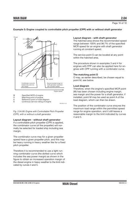
- Page 42 and 43: MAN B&W 2.04 Engine Layout and Load
- Page 44 and 45: MAN B&W 2.04 Line 4: Represents the
- Page 46 and 47: MAN B&W 2.04 110 100 90 80 70 60 50
- Page 48 and 49: MAN B&W 2.04 Example 2: Special run
- Page 52 and 53: MAN B&W 2.05 Diagram for actual pro
- Page 55 and 56: MAN B&W 2.07 SFOC for High Efficien
- Page 57 and 58: MAN B&W 2.08 Examples of Graphic Ca
- Page 59 and 60: MAN B&W 2.09 SFOC for S50ME-B8 with
- Page 61 and 62: MAN B&W 2.10 Diagram b ����
- Page 63: MAN B&W 2.12 Emission Control IMO N
- Page 67 and 68: MAN B&W 3.01 Turbocharger Selection
- Page 69 and 70: MAN B&W 3.02 Turbocharger MAN B&W S
- Page 71: MAN B&W 3.03 Air Orifice Air Proces
- Page 75 and 76: MAN B&W 4.01 Electricity Production
- Page 77 and 78: MAN B&W 4.01 Designation of PTO For
- Page 79 and 80: MAN B&W 4.01 The power from the cra
- Page 81 and 82: MAN B&W 4.02 � � � � � Th
- Page 83 and 84: MAN B&W 4.03 Pos. 1 Special face on
- Page 85 and 86: MAN B&W 4.03 DMG/CFE Generators Opt
- Page 87 and 88: MAN B&W 4.03 In such a case, the pr
- Page 89 and 90: MAN B&W 4.04 combinator mode. This
- Page 91 and 92: MAN B&W Waste Heat Recovery Systems
- Page 93 and 94: MAN Diesel 4.06 L16/24 GenSet Data
- Page 95 and 96: MAN Diesel 4.07 L21/31 GenSet Data
- Page 97 and 98: MAN Diesel 4.07 L21/31 GenSet Data
- Page 99 and 100: MAN Diesel 4.08 L23/30H GenSet Data
- Page 101 and 102:
MAN Diesel 4.09 L27/38 GenSet Data
- Page 103 and 104:
MAN Diesel 4.09 L27/38 GenSet Data
- Page 105:
MAN Diesel 4.10 L28/32H GenSet Data
- Page 109 and 110:
MAN B&W 5.01 Space Requirements and
- Page 111 and 112:
MAN B&W 5.02 Cyl. No. 5 6 7 8 9 A 8
- Page 113 and 114:
MAN B&W 5.03 Crane beam for turboch
- Page 115 and 116:
MAN B&W 5.03 Crane beam for overhau
- Page 117 and 118:
MAN B&W 5.04 Overhaul with MAN B&W
- Page 119 and 120:
MAN B&W 5.05 Engine Outline, Galler
- Page 121 and 122:
MAN B&W 5.06 1,673 MAN B&W S50ME-B8
- Page 123 and 124:
MAN B&W 5.06 2,600 2,875 Fig. 5.06.
- Page 125 and 126:
MAN B&W 5.06 MAN B&W S50ME-B8 1,700
- Page 127 and 128:
MAN B&W 5.06 895 2,875 4,400 Y Y MA
- Page 129 and 130:
MAN B&W 5.08 Mass of Water and Oil
- Page 131 and 132:
MAN B&W 5.09 Fig. 5.09.01b: Engine
- Page 133 and 134:
MAN B&W 5.09 MAN B&W S50ME-B8 AU 1,
- Page 135 and 136:
MAN B&W 5.10 �������
- Page 137 and 138:
MAN B&W 5.10 ABB Type TPL/A100 B F
- Page 139 and 140:
MAN B&W 5.10 Counterflanges, Connec
- Page 141 and 142:
MAN B&W 5.10 MHI Type MET Dia TPL W
- Page 143 and 144:
MAN B&W 5.12 Epoxy Chocks Arrangeme
- Page 145 and 146:
MAN B&W 5.12 � ��� Fig.5.12
- Page 147 and 148:
MAN B&W 5.13 Engine Top Bracing The
- Page 149 and 150:
MAN B&W 5.14 Mechanical Top Bracing
- Page 151 and 152:
MAN B&W 5.16 Components for Engine
- Page 153 and 154:
MAN B&W 5.16 EICU (Engine Interface
- Page 155 and 156:
MAN B&W 5.17 Shaftline Earthing Dev
- Page 157 and 158:
MAN B&W 5.17 When a generator is fi
- Page 159 and 160:
MAN B&W 5.18 Data Sheet for Propell
- Page 161 and 162:
MAN B&W 5.18 Servo oil system for V
- Page 163 and 164:
MAN B&W 5.18 Alphatronic 2000 Propu
- Page 165:
MAN B&W 5.18 Renk KAZ Clutch for au
- Page 169 and 170:
MAN B&W 6.01 Calculation of List of
- Page 171 and 172:
MAN B&W 6.03 List of Capacities for
- Page 173 and 174:
MAN B&W 6.03 List of Capacities for
- Page 175 and 176:
MAN B&W 6.03 List of Capacities for
- Page 177 and 178:
MAN B&W 6.04 The derated cooler cap
- Page 179 and 180:
MAN B&W 6.04 MAN B&W S50ME-B8-TII N
- Page 181 and 182:
MAN B&W 6.04 Jacket Cooling Water T
- Page 183 and 184:
MAN B&W 6.04 Exhaust Gas Amount and
- Page 185 and 186:
MAN B&W 6.04 Page 10 of 12 ∆M amb
- Page 187:
MAN B&W 6.04 Final calculation By m
- Page 191 and 192:
MAN B&W 7.01 Pressurised Fuel Oil S
- Page 193 and 194:
MAN B&W 7.01 Drain of clean fuel oi
- Page 195 and 196:
MAN B&W 7.03 Fuel Oil Pipes and Dra
- Page 197 and 198:
MAN B&W 7.04 Heat Loss in Piping Pi
- Page 199 and 200:
MAN B&W 7.05 Components for Fuel Oi
- Page 201 and 202:
MAN B&W 7.05 Fuel oil filter The fi
- Page 203:
MAN B&W 7.06 Diesel oil service tan
- Page 207 and 208:
MAN B&W 8.01 Lubricating and Coolin
- Page 209 and 210:
MAN B&W 8.02 Hydraulic Power Supply
- Page 211 and 212:
MAN B&W 8.03 Lubricating Oil Pipes
- Page 213 and 214:
MAN B&W 8.04 Lubricating Oil Centri
- Page 215 and 216:
MAN B&W 8.05 Lubricating oil full f
- Page 217 and 218:
MAN B&W 8.06 Lubricating Oil Tank O
- Page 219 and 220:
MAN B&W 8.07 Crankcase Venting and
- Page 221:
MAN B&W Separate System for Hydraul
- Page 225 and 226:
MAN B&W 9.01 Cylinder Lubricating O
- Page 227 and 228:
MAN B&W 9.02 Basic and minimum sett
- Page 229 and 230:
MAN B&W 9.02 300 bar system oil Fee
- Page 231:
MAN B&W 9.02 From cylinder oil serv
- Page 235:
MAN B&W 10.01 Stuffing Box Drain Oi
- Page 239 and 240:
MAN B&W 11.01 Central Cooling Water
- Page 241 and 242:
MAN B&W 11.03 Components for Centra
- Page 243:
MAN B&W MAN Diesel Seawater Cooling
- Page 246 and 247:
MAN B&W 12.02 Seawater Cooling Syst
- Page 248 and 249:
MAN B&W 12.04 Components for Seawat
- Page 250 and 251:
MAN B&W 12.06 Jacket Cooling Water
- Page 252 and 253:
MAN B&W 12.07 Deaerating tank øK
- Page 255:
MAN B&W MAN Diesel Starting and Con
- Page 258 and 259:
MAN B&W 13.02 Components for Starti
- Page 260 and 261:
MAN B&W 13.03 Exhaust Valve Air Spr
- Page 263:
MAN B&W MAN Diesel Scavenge Air 14
- Page 266 and 267:
MAN B&W 14.02 Auxiliary Blowers The
- Page 268 and 269:
MAN B&W 14.02 Operation Panel for t
- Page 270 and 271:
MAN B&W 14.04 Electric Motor for Au
- Page 272 and 273:
MAN B&W 14.05 Auto Pump Overboard S
- Page 274 and 275:
MAN B&W 14.07 Fire Extinguishing Sy
- Page 277:
MAN B&W MAN Diesel Exhaust Gas 15
- Page 280 and 281:
MAN B&W 15.02 Exhaust Gas Pipes TI
- Page 282 and 283:
MAN B&W 15.03 Exhaust Gas System fo
- Page 284 and 285:
MAN B&W 15.04 Exhaust gas silencer
- Page 286 and 287:
MAN B&W 15.05 Measuring Back Pressu
- Page 288 and 289:
MAN B&W 15.06 Forces and Moments at
- Page 290 and 291:
MAN B&W 15.06 �� Table 5.06.04
- Page 293:
MAN B&W MAN Diesel Engine Control S
- Page 296 and 297:
MAN B&W 16.01 Engine Control System
- Page 298 and 299:
MAN B&W 16.01 Engine Control System
- Page 300 and 301:
MAN B&W 16.01 Pneumatic Manoeuvring
- Page 303:
MAN B&W MAN Diesel Vibration Aspect
- Page 306 and 307:
MAN B&W 17.02 2nd Order Moments on
- Page 308 and 309:
MAN B&W 17.02 1st Order Moments on
- Page 310 and 311:
MAN B&W 17.03 Moment compensator Af
- Page 312 and 313:
MAN B&W 17.05 Guide Force Moments T
- Page 314 and 315:
MAN B&W 17.05 As the deflection sha
- Page 316 and 317:
MAN B&W 17.06 Critical Running When
- Page 319:
MAN B&W Monitoring Systems and Inst
- Page 322 and 323:
MAN B&W 18.02 PMI System, Type PT/S
- Page 324 and 325:
MAN B&W 18.03 CoCoS Systems The Com
- Page 326 and 327:
MAN B&W 18.04 Alarm - Slow Down and
- Page 328 and 329:
MAN B&W 18.04 Alarms for UMS - Clas
- Page 330 and 331:
MAN B&W 18.04 Alarms for UMS - Clas
- Page 332 and 333:
MAN B&W 18.04 Shut down for AMS and
- Page 334 and 335:
MAN B&W 18.05 Local instruments Rem
- Page 336 and 337:
MAN B&W 18.06 Other Alarm Functions
- Page 338 and 339:
MAN B&W 18.06 Bearing Wear Monitori
- Page 340 and 341:
MAN B&W 18.06 Control Devices Senso
- Page 343:
MAN B&W Dispatch Pattern, Testing,
- Page 346 and 347:
MAN B&W 19.01 MAN Diesel’s recomm
- Page 348 and 349:
MAN B&W 19.03 Dispatch Pattern This
- Page 350 and 351:
MAN B&W 19.05 Shop Test Minimum del
- Page 352 and 353:
MAN B&W 19.06 Fuel valve, plate 909
- Page 354 and 355:
MAN B&W 19.07 Exhaust valve, sectio
- Page 356 and 357:
MAN B&W 19.08 Table B: Page 2 of 2
- Page 358 and 359:
MAN B&W 19.10 List of Standard Tool
- Page 361:
MAN B&W MAN Diesel Project Suppport
- Page 364 and 365:
MAN B&W 20.02 Computerised Engine A
- Page 366 and 367:
MAN B&W 20.03 Copenhagen Standard E
- Page 368 and 369:
MAN B&W 20.04 Main Section 939 Engi
- Page 370 and 371:
MAN B&W 20.04 Engine production and
- Page 373 and 374:
MAN B&W Appendix A Symbols for Pipi
- Page 375:
MAN B&W Appendix A No. Symbol Symbo