VAD, VAG (GB) - System Control Engineering
VAD, VAG (GB) - System Control Engineering
VAD, VAG (GB) - System Control Engineering

You also want an ePaper? Increase the reach of your titles
YUMPU automatically turns print PDFs into web optimized ePapers that Google loves.
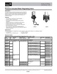
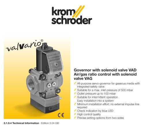
Governor with solenoid valve <strong>VAD</strong><br />
Air/gas ratio control with solenoid<br />
valve <strong>VAG</strong><br />
All-purpose servo-governor for gaseous media with<br />
integrated safety valve<br />
Suitable for a max. inlet pressure of 500 mbar<br />
Outlet pressure up to 100 mbar<br />
Suitable for intermittent operation<br />
Easy installation L1 into (+) a system<br />
Minimum installation effort: no external impulse line<br />
required<br />
Check indication by blue LED<br />
High control quality N (–)<br />
Precise setting options from two sides<br />
3.1.0.4 Technical Information · Edition 3.04 <strong>GB</strong>
Table of Contents<br />
Governor with solenoid valve <strong>VAD</strong> Air/gas ratio<br />
control with solenoid valve <strong>VAG</strong> . . . . . . . . . . . . 1<br />
Table of Contents . . . . . . . . . . . . . . . . . . . . . . . . 2<br />
Application . . . . . . . . . . . . . . . . . . . . . . . . . . . . . . 3<br />
Application examples . . . . . . . . . . . . . . . . . . . . . . 4<br />
Constant pressure control . . . . . . . . . . . . . . . . . . . . . . .4<br />
Constant pressure control with two solenoid valves . . .4<br />
Constant pressure control with max. pressure switch . .5<br />
Constant pressure control with non-controlled pilot gas<br />
outlet . . . . . . . . . . . . . . . . . . . . . . . . . . . . . . . . . . . . . . .5<br />
Modulating control with two solenoid valves . . . . . . . . .6<br />
Modulating control . . . . . . . . . . . . . . . . . . . . . . . . . . . .6<br />
High/Low control . . . . . . . . . . . . . . . . . . . . . . . . . . . . . .7<br />
Modulating control with two solenoid valves and inlet<br />
pressure switch . . . . . . . . . . . . . . . . . . . . . . . . . . . . . . .7<br />
Certification . . . . . . . . . . . . . . . . . . . . . . . . . . . . . 8<br />
Function . . . . . . . . . . . . . . . . . . . . . . . . . . . . . . . . 9<br />
Governor for gas <strong>VAD</strong> . . . . . . . . . . . . . . . . . . . . . . 9<br />
Air/gas ratio control <strong>VAG</strong> . . . . . . . . . . . . . . . . . . . 10<br />
<strong>VAD</strong>, <strong>VAG</strong> connection diagram . . . . . . . . . . . . . . 11<br />
Replacement possibility for MODULINE<br />
governors with solenoid valve . . . . . . . . . . . . . 12<br />
Flow rate . . . . . . . . . . . . . . . . . . . . . . . . . . . . . . 14<br />
Selection example for <strong>VAD</strong> . . . . . . . . . . . . . . . . . 14<br />
Selection example for <strong>VAG</strong> . . . . . . . . . . . . . . . . . 15<br />
Selection . . . . . . . . . . . . . . . . . . . . . . . . . . . . . . 16<br />
Project planning information . . . . . . . . . . . . . . 18<br />
Installation . . . . . . . . . . . . . . . . . . . . . . . . . . . . . . 18<br />
Accessories . . . . . . . . . . . . . . . . . . . . . . . . . . . . 20<br />
Pressure switch for gas DG..C . . . . . . . . . . . . . . 20<br />
Bypass valve VAS 1 . . . . . . . . . . . . . . . . . . . . . . 20<br />
Technical data . . . . . . . . . . . . . . . . . . . . . . . . . . 21<br />
<strong>VAD</strong> . . . . . . . . . . . . . . . . . . . . . . . . . . . . . . . . . . . 21<br />
<strong>VAG</strong> . . . . . . . . . . . . . . . . . . . . . . . . . . . . . . . . . . 21<br />
Dimensions . . . . . . . . . . . . . . . . . . . . . . . . . . . . . 22<br />
Maintenance cycles . . . . . . . . . . . . . . . . . . . . . 23<br />
Contact . . . . . . . . . . . . . . . . . . . . . . . . . . . . . . . . 24<br />
<strong>VAD</strong>, <strong>VAG</strong> · Edition 3.04<br />
= To be continued, = End of chapter<br />
2
<strong>VAD</strong><br />
Application<br />
Governor <strong>VAD</strong> and air/gas ratio control<br />
<strong>VAG</strong> incorporating servo technology<br />
for shut-off and precise control<br />
of the gas supply to gas burners and<br />
gas appliances. For use in gas control<br />
and safety systems in all sectors<br />
of the iron, steel, glass and ceramics<br />
industries, also in commercial heat<br />
generation, such as the packaging,<br />
paper and foodstuffs industries.<br />
<strong>VAG</strong><br />
<strong>VAD</strong>: Constant governor, Class<br />
A, with high control accuracy, for<br />
excess air burners, atmospheric<br />
burners or single-stage force draught<br />
burners. Pressure preset via setpoint<br />
spring.<br />
<strong>VAG</strong>: Air/gas ratio control, Class A,<br />
for maintaining a constant air/gas<br />
pressure ratio for modulating-controlled<br />
burners or with VAS 1 bypass<br />
valve for step-by-step-controlled<br />
burners. Pressure preset by the air<br />
control line.<br />
The <strong>VAG</strong> can also be used as a zero<br />
governor for gas engines.<br />
Easy-to-service<br />
measuring connections.<br />
<strong>VAD</strong>: Gas outlet<br />
pressure p G<br />
<strong>VAG</strong>: Also air control<br />
pressure p L<br />
<strong>VAD</strong>, <strong>VAG</strong> · Edition 3.04<br />
3
Application<br />
<strong>VAD</strong><br />
Application examples<br />
Constant pressure control<br />
The governor with solenoid valve <strong>VAD</strong><br />
maintains the set gas outlet pressure<br />
p G constant when subject to differing<br />
flow rates. If a second solenoid<br />
valve is used upstream of the <strong>VAD</strong>,<br />
this complies with the requirements<br />
of EN 746-2 for two Classe A valves<br />
connected in series.<br />
VAS<br />
<strong>VAD</strong><br />
Constant pressure control with<br />
two solenoid valves<br />
The governor with solenoid valve <strong>VAD</strong><br />
maintains the set gas outlet pressure<br />
p G constant when subject to differing<br />
flow rates. The gas line is two Class<br />
A shut-off valves connected in series,<br />
in accordance with the requirements<br />
of EN 746-2.<br />
<br />
<strong>VAD</strong>, <strong>VAG</strong> · Edition 3.04<br />
4
Application<br />
Application examples<br />
DG..C min.<br />
VAS<br />
DG..C max.<br />
Constant pressure control with<br />
max. pressure switch<br />
In this example, the minimum inlet<br />
pressure p e and the maximum outlet<br />
pressure p G are monitored with the<br />
pressure switches DG..C. The simple<br />
attachment of the pressure switch<br />
module makes installation easier.<br />
<strong>VAD</strong><br />
DG..C min.<br />
VAS<br />
<strong>VAD</strong><br />
VAS 1<br />
DG..C max.<br />
Constant pressure control with<br />
non-controlled pilot gas outlet<br />
In this application, the pilot burner is<br />
supplied with a high inlet pressure<br />
via the pilot gas outlet. Here as well,<br />
the simple attachment of the bypass<br />
valve module makes installation<br />
easier. The minimum inlet pressure<br />
p e and the maximum outlet pressure<br />
p G are monitored with the pressure<br />
switches DG..C.<br />
<br />
<strong>VAD</strong>, <strong>VAG</strong> · Edition 3.04<br />
5
Application<br />
Application examples<br />
IC<br />
<br />
BVA<br />
<strong>VAG</strong><br />
p L<br />
Modulating control<br />
The gas outlet pressure p G is controlled<br />
via the air/gas ratio control<br />
with solenoid valve <strong>VAG</strong>. The gas<br />
outlet pressure p G follows the changing<br />
air control pressure p L . The ratio<br />
of gas pressure to air pressure remains<br />
constant. The <strong>VAG</strong> is suitable<br />
for a control range up to 10:1.<br />
If a second solenoid valve is used<br />
upstream of the <strong>VAG</strong>, this complies<br />
with the requirements of EN 746-2<br />
for two Class A valves connected<br />
in series.<br />
<br />
<br />
<br />
<br />
<br />
<br />
Modulating control with two<br />
solenoid valves<br />
The gas outlet pressure p G is controlled<br />
via the air/gas ratio control<br />
with solenoid valve <strong>VAG</strong>. The gas<br />
outlet pressure p G follows the changing<br />
air control pressure p L . The ratio<br />
of gas pressure to air pressure remains<br />
constant. The <strong>VAG</strong> is suitable<br />
for a control range up to 10:1.<br />
The gas line is two Class A shut-off<br />
valves connected in series, in accordance<br />
with the requirements of<br />
EN 746-2.<br />
<br />
<strong>VAD</strong>, <strong>VAG</strong> · Edition 3.04<br />
6
Application<br />
Application examples<br />
<br />
<br />
<br />
Modulating control with two<br />
solenoid valves and inlet pressure<br />
switch<br />
In this case, the minimum inlet<br />
pressure p e is monitored by the<br />
pressure switch DG..C. The simple<br />
attachment of the pressure switch<br />
module makes installation easier.<br />
<br />
<br />
<br />
<br />
<br />
<br />
<br />
<br />
<br />
High/Low control<br />
At high fire, the gas outlet pressure<br />
p G follows the air control pressure<br />
p L . The ratio of gas pressure to air<br />
pressure remains constant. Low fire<br />
is determined via the bypass valve.<br />
Here as well, the simple attachment<br />
of the bypass valve module makes<br />
installation easier. <br />
<br />
<br />
<br />
<strong>VAD</strong>, <strong>VAG</strong> · Edition 3.04<br />
7
Certification<br />
EC type-tested and certified<br />
pursuant to<br />
– Gas Appliances Directive<br />
(90/396/EEC) in conjunction with<br />
EN 161, EN 88 and EN 126,<br />
– Machinery Directive<br />
(89/392/EEC),<br />
– Low Voltage Directive<br />
(73/23/EEC) in conjunction with<br />
the relevant standards,<br />
– EMC Directive (89/336/EEC) in<br />
conjunction with EN 55014.<br />
FM, UL and CSA approval in preparation.<br />
<strong>VAD</strong>, <strong>VAG</strong> · Edition 3.04<br />
8
Function<br />
The governor is closed when it is disconnected<br />
from the power supply.<br />
Opening: Alternating voltage is applied<br />
and fed to the solenoid coil via<br />
a rectifier with a suppressor circuit.<br />
The blue LED lights up. The coil’s<br />
magnetic field pulls the armature<br />
upwards and clears the supply<br />
nozzle for the gas inlet pressure p e .<br />
The gas passes through the internal<br />
impulse tube to the adjustment diaphragm<br />
and then pushes the valve<br />
seat open. The outlet pressure is applied<br />
to the servo-diaphragm via the<br />
internal bypass. The servo-governor<br />
then maintains a set constant outlet<br />
pressure p G .<br />
Governor for gas <strong>VAD</strong><br />
The nominal outlet pressure p G is<br />
defined by the control spring.<br />
<br />
<strong>VAD</strong>, <strong>VAG</strong> · Edition 3.04<br />
9
Function<br />
Air/gas ratio control <strong>VAG</strong><br />
The air/gas ratio control <strong>VAG</strong> controls the outlet pressure p G equal to the<br />
variable air control pressure p L . The ratio of gas pressure to air pressure<br />
remains constant: 1:1.<br />
The <strong>VAG</strong> is suitable for a control range up to 10:1. <br />
p L<br />
<strong>VAD</strong>, <strong>VAG</strong> · Edition 3.04<br />
10
Function<br />
<strong>VAD</strong>, <strong>VAG</strong> connection diagram<br />
L1 (+)<br />
N (–)<br />
<strong>VAD</strong>, <strong>VAG</strong> · Edition 3.04<br />
11
Replacement possibility for MODULINE governors with solenoid valve<br />
GVS, GVI and GVIB are to be replaced by <strong>VAD</strong>, <strong>VAG</strong> and <strong>VAG</strong>+VAS<br />
GVS Governor with solenoid valve Governor with solenoid valve <strong>VAD</strong><br />
GVI Air/gas ratio control with solenoid valve Air/gas ratio control with solenoid valve <strong>VAG</strong><br />
GVIB<br />
Air/gas ratio control with solenoid valve<br />
and bypass valve<br />
Air/gas ratio control with solenoid valve<br />
and bypass valve<br />
<strong>VAG</strong>+VAS<br />
3<br />
/8 Size 1, DN 15 or 25, Rp 3 /8 on request<br />
115 1⁄2 Size 1, DN 15 or 25, Rp 1⁄2 Size 1 DN 15 115<br />
125 3⁄4 Size 1, DN 15 or 25, Rp 3⁄4 Size 1 DN 20 120<br />
1 Size 1, DN 15 or 25, Rp 1 Size 1 DN 25 125<br />
232 1 Size 2, DN 32 or 40, Rp 1<br />
240 11⁄2 Size 2, DN 32 or 40, Rp 11⁄2 Size 2 DN 40 240<br />
350<br />
11⁄2<br />
Size 3, DN 50, Rp 11⁄2<br />
2 Size 3, DN 50, Rp 2 Size 3 DN 50 350<br />
ML<br />
MODULINE + connection flanges Rp internal thread<br />
R<br />
Rp internal thread<br />
01 Max. inlet pressure p e max. : 100 mbar Max. inlet pressure p e max. : 500 mbar <br />
02 200 mbar 500 mbar <br />
Quick opening Quick opening /N<br />
K Mains voltage: 24 V DC Mains voltage: 24 V DC K<br />
Q 120 V AC 120 V AC Q<br />
T 220/240 V AC 230 V AC W<br />
<br />
<strong>VAD</strong>, <strong>VAG</strong> · Edition 3.04<br />
12
Replacement possibility for MODULINE governors with solenoid valve<br />
Cont.<br />
3 Electrical connection via terminals Electrical connection via terminals <br />
6 Electrical connection via standard socket on request<br />
S Position indicator on request<br />
G Position indicator with gold contacts on request<br />
M Suitable for biologically produced methane Suitable for biologically produced methane <br />
Pressure test point at the inlet Pressure test point at the inlet and outlet* <br />
Outlet pressure p G : 2.5 – 25 mbar -25<br />
Outlet pressure p G : 2 – 90 mbar 5 – 50 mbar -50<br />
10 – 100 mbar -100<br />
Standard seat<br />
A<br />
GVS 115ML01T3 Example Example <strong>VAD</strong> 125R/NW-100A<br />
with Rp 1 connection flanges<br />
with test points<br />
standard, available<br />
* Pressure test points may be attached at the left<br />
and/or right-hand side. <br />
<strong>VAD</strong>, <strong>VAG</strong> · Edition 3.04<br />
13
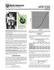
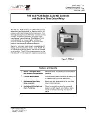
∆p [mbar]<br />
500<br />
400<br />
300<br />
200<br />
100<br />
80<br />
60<br />
50<br />
40<br />
30<br />
20<br />
10<br />
8<br />
5<br />
3<br />
<strong>VAD</strong>, <strong>VAG</strong> 115..B<br />
<strong>VAD</strong>, <strong>VAG</strong> 125..A<br />
<strong>VAD</strong>, <strong>VAG</strong> 240..A<br />
P3<br />
<br />
P2<br />
<br />
<strong>VAD</strong>, <strong>VAG</strong> 350..A<br />
P1<br />
<br />
Selection example for <strong>VAD</strong><br />
Natural gas<br />
Inlet pressure p e = 100 mbar<br />
Outlet pressure p G = 40 mbar<br />
Flow rate V . max = 50 m 3 /h<br />
The selected control ratio from<br />
high-fire to low-fire rate is Rv = 5:1<br />
High fire<br />
Δp = p e - p G = 60 mbar<br />
Point P1<br />
Select: <strong>VAD</strong> 125..A<br />
Low fire<br />
V . G min = V. G max = 10 m<br />
Rv<br />
3 /h<br />
Δp = p e - p G = 60 mbar<br />
Point P2<br />
Select: <strong>VAD</strong> 125..A<br />
1<br />
2<br />
3<br />
2<br />
0,3 0,4 0,6 1 2 3 4 5 8 10 20 30 40 60 100 200<br />
0,2 0,3 0,5 0,8 1 2 3 4 5 8 10 20 30 40 60 100<br />
0,3<br />
0,5 0,8 1 2 3 4 5 8 10 20 30 40<br />
Flow rate<br />
The characteristic flow rate curves<br />
have been measured with the specified<br />
flanges and a fitted strainer. If<br />
two or more valves are combined<br />
the pressure loss per individual valve<br />
drops by approx. 5%.<br />
= Natural gas<br />
= LPG<br />
= Air<br />
60 100<br />
200<br />
V' [m 3 /h (n)]<br />
Point P1 and point P2 must be<br />
within the working range of a unit<br />
size. We recommend that you select<br />
the smallest size to achieve the best<br />
control properties. <br />
<strong>VAD</strong>, <strong>VAG</strong> · Edition 3.04<br />
14
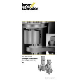
∆p [mbar]<br />
1<br />
2<br />
3<br />
500<br />
400<br />
300<br />
200<br />
100<br />
80<br />
60<br />
50<br />
40<br />
30<br />
20<br />
10<br />
8<br />
5<br />
3<br />
2<br />
0,3 0,4 0,6 1 2 3 4 5 8 10 20 30 40 60 100 200<br />
0,2 0,3 0,5 0,8 1 2 3 4 5 8 10 20 30 40 60 100<br />
0,3<br />
<strong>VAD</strong>, <strong>VAG</strong> 115..B<br />
<strong>VAD</strong>, <strong>VAG</strong> 125..A<br />
<strong>VAD</strong>, <strong>VAG</strong> 240..A<br />
P3<br />
<br />
P2<br />
<br />
<strong>VAD</strong>, <strong>VAG</strong> 350..A<br />
P1<br />
<br />
0,5 0,8 1 2 3 4 5 8 10 20 30 40<br />
60 100<br />
200<br />
V' [m 3 /h (n)]<br />
Selection example for <strong>VAG</strong><br />
Natural gas<br />
Inlet pressure p e = 100 mbar<br />
Outlet pressure p G max = 40 mbar<br />
Flow rate V . max = 50 m 3 /h<br />
The selected control ratio from<br />
high-fire to low-fire rate is Rv = 5:1<br />
High fire<br />
Δp = p e - p G max = 60 mbar<br />
Point P1<br />
Select: <strong>VAG</strong> 125..A<br />
Low fire<br />
p G min = p G max<br />
Rv 2 = 1.6 mbar<br />
V . G min = V. G max = 10 m<br />
Rv<br />
3 /h<br />
Δp = p e - p G min = 98.4 mbar<br />
Point P3<br />
Select: <strong>VAG</strong> 125..A<br />
Point P1 and point P3 must be<br />
within the working range of a unit<br />
size. We recommend that you select<br />
the smallest size to achieve the best<br />
control properties. <br />
<strong>VAD</strong>, <strong>VAG</strong> · Edition 3.04<br />
15
Selection<br />
<strong>VAD</strong>: Governor with solenoid valve / <strong>VAG</strong>: Air/gas ratio control with solenoid valve<br />
– 15 20 25 32 40 50 /–* /15 /20 /25 /32 /40 /50 R /N K Q W -25 -50 -100 A B K E<br />
<strong>VAD</strong> 1 <br />
<strong>VAD</strong> 2 <br />
<strong>VAD</strong> 3 <br />
<strong>VAG</strong> 1 <br />
<strong>VAG</strong> 2 <br />
<strong>VAG</strong> 3 <br />
Inlet flange nominal size<br />
– = no inlet flange<br />
Outlet flange nominal size<br />
/– = no outlet flange*<br />
Specification may be omitted if outlet = inlet<br />
Rp internal thread = R<br />
Quick opening, quick closing = /N<br />
Mains voltage: 24 V DC = K<br />
120 V AC; 50/60 Hz = Q<br />
230 V AC; 50/60 Hz = W<br />
Max. outlet pressure p G max. for <strong>VAD</strong>: 2.5 to 25 mbar = -25<br />
5.0 to 50 mbar = -50<br />
10 to 100 mbar = -100<br />
Standard valve seat = A<br />
Reduced valve seat = B<br />
Connection kit <strong>VAG</strong> for air control pressure p L : 1 plastic hose coupling, 2 screw plugs = K<br />
1 compression fitting, 2 test points p G and p L = E<br />
Accessories attached at the right-hand side: 2 screw plugs<br />
2 test points p e and p G<br />
Gas pressure switch DG..C (see table) at the inlet<br />
Gas pressure switch DG..C (see table) at the outlet<br />
Bypass valve VAS 1<br />
Accessories attached at the left-hand side: 2 screw plugs<br />
2 test points p e and p G<br />
Gas pressure switch DG..C (see table) at the inlet<br />
Gas pressure switch DG..C (see table) at the outlet<br />
Bypass valve VAS 1<br />
* Bei einer Bestellung muss angeben werden, an welchen Ausgangsflansch der Druckregler angebaut wird. <strong>GB</strong> <strong>GB</strong> <strong>GB</strong> <strong>GB</strong><br />
Order example<br />
<br />
<strong>VAD</strong>, <strong>VAG</strong> · Edition 3.04<br />
<strong>VAG</strong> 125R/NWAK, 2 screw plugs attached at the right-hand side<br />
2 test points attached at the left-hand side<br />
= standard<br />
= available<br />
16
Selection<br />
Pressure switch for gas DG..C<br />
Type Adjusting range<br />
[mbar]<br />
DG 17/VC 2 – 17<br />
DG 40/VC 5 – 40<br />
DG 110/VC 30 – 110<br />
DG 300/VC 100 – 300<br />
<br />
<strong>VAD</strong>, <strong>VAG</strong> · Edition 3.04<br />
17
Project planning information<br />
The inlet pressure p e and the outlet<br />
pressure p G can be measured on<br />
both sides of the valve body.<br />
<strong>VAD</strong>: Measurement point for the gas outlet<br />
pressure p G on the governor body.<br />
> 20<br />
mm<br />
The <strong>VAD</strong>, <strong>VAG</strong> may not be in contact<br />
with masonry. Minimum clearance<br />
20 mm.<br />
p e<br />
p G<br />
p G<br />
p L<br />
<strong>VAG</strong>: Additional measurement point<br />
for the air control pressure p L on the<br />
governor body.<br />
<strong>VAD</strong>, <strong>VAG</strong>: To increase the control<br />
accuracy, an external impulse line<br />
can be connected to the pressure<br />
test point p G .<br />
a a<br />
GFK<br />
GFK<br />
<strong>VAD</strong><br />
<strong>VAG</strong><br />
Ensure that there is sufficient installation<br />
space around the flange screws<br />
and the actuator.<br />
Sealing material and thread cuttings<br />
must not be allowed to get into the<br />
valve housing.<br />
We recommend that a filter be installed<br />
upstream of every system.<br />
Installation<br />
Installation position vertical or horizontal,<br />
not upside down.<br />
> +80 ° C<br />
The solenoid body heats up during<br />
operation – up to 90°C depending on<br />
ambient temperature and voltage.<br />
To ensure that the air/gas ratio control<br />
<strong>VAG</strong> can react quickly when<br />
the load is changed, the impulse<br />
line p L should be kept as short as<br />
possible.<br />
Do not store or install the unit in the<br />
open air.<br />
<br />
<strong>VAD</strong>, <strong>VAG</strong> · Edition 3.04<br />
18
Project planning information<br />
Installation<br />
If more than three valVario controls<br />
are installed in line, the controls must<br />
be supported.<br />
<strong>VAD</strong>, <strong>VAG</strong> · Edition 3.04<br />
19
pe<br />
<br />
Accessories<br />
Pressure switch for gas DG..C<br />
Scope of delivery:<br />
1 x pressure switch for gas,<br />
2 x retaining screws,<br />
2 x sealing rings.<br />
Monitor the inlet pressure p e : The plug of the pressure<br />
switch for gas DG..C points towards the inlet flange.<br />
Monitor the outlet pressure p G : The plug of the pressure<br />
switch for gas DG..C points towards the outlet flange.<br />
1<br />
2<br />
3<br />
4<br />
5<br />
Bypass valve VAS 1<br />
Delivery for VAS 1 attached to <strong>VAD</strong> 1, <strong>VAG</strong> 1:<br />
1 1 x bypass valve VAS 1 /<br />
2 1 x connection pipe, 1 x sealing stopper, if the bypass valve at the<br />
outlet side has a threaded flange, or 2 x connection pipes, if the bypass<br />
valve has a dummy flange at the outlet side /<br />
3 4 x O-rings / 4 4 x double nuts / 5 4 x connection parts.<br />
1<br />
2<br />
3<br />
4<br />
5<br />
Delivery for VAS 1 attached to <strong>VAD</strong> 2, <strong>VAD</strong> 3, <strong>VAG</strong> 2, <strong>VAG</strong> 3:<br />
1 1 x bypass valve VAS 1 /<br />
2 1 x connection pipe, 1 x sealing stopper, if the bypass valve at the<br />
outlet side has a threaded flange, or 2 x connection pipes, if the bypass<br />
valve has a dummy flange at the outlet side /<br />
3 4 x O-rings / 4 4 x washer / 5 4 x connection parts.<br />
<strong>VAD</strong>, <strong>VAG</strong> · Edition 3.04<br />
20
Technical data<br />
Types of gas: Natural gas, town<br />
gas, LPG (gaseous), biologically<br />
produced methane (max. 0.1 %-byvol.<br />
H 2 S); other gases on request.<br />
The gas must be dry in all temperature<br />
conditions and must not<br />
condense.<br />
Inlet pressure range p e :<br />
10 – 500 mbar.<br />
Opening time of the solenoid valve:<br />
Quick opening: ≤ 0.5 s.<br />
Closing time:<br />
Quick closing: < 1 s.<br />
Ambient temperature:<br />
-20 – 60°C, no condensation permitted.<br />
Class A safety valve pursuant to<br />
EN 161.<br />
<strong>Control</strong> class A to EN 88.<br />
<strong>Control</strong> range: up to 10:1.<br />
Mains voltage:<br />
230 V AC, +10/-15%, 50/60 Hz;<br />
120 V AC, +10/-15%, 50/60 Hz;<br />
24 V DC, +20/-20%.<br />
Cable gland:<br />
M 20 x 1.5.<br />
Power consumption:<br />
Type 24 V DC 120 V AC 230 V AC<br />
[W] [W] [W]<br />
<strong>VAD</strong>/<strong>VAG</strong> 1 25 32 35<br />
<strong>VAD</strong>/<strong>VAG</strong> 2 48 59 58<br />
<strong>VAD</strong>/<strong>VAG</strong> 3 48 59 58<br />
Enclosure: IP 65.<br />
Duty cycle: 100%.<br />
Power factor of the solenoid coil:<br />
cos ϕ = 1.<br />
Valve housing: Aluminium,<br />
Valve seal: NBR.<br />
Connection flanges with internal<br />
thread: Rp to ISO 7-1.<br />
<strong>VAD</strong><br />
Outlet pressure p G : 2.5 – 25 mbar,<br />
5.0 – 50 mbar,<br />
10 – 100 mbar.<br />
<strong>VAG</strong><br />
Outlet pressure p G : 0.5 – 100 mbar.<br />
Adjusting range at min. flow:<br />
±5 mbar.<br />
Transmission ratio of gas to air:<br />
1:1<br />
The inlet pressure must always be<br />
higher than the air control pressure.<br />
Connection of the air control pressure<br />
p L :<br />
1 1/8” coupling for plastic hose (internal<br />
dia. 3.9, external dia. 6.1) or<br />
1 compression fitting for tube 6x1.<br />
<br />
<strong>VAD</strong>, <strong>VAG</strong> · Edition 3.04<br />
21
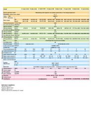
Dimensions<br />
Type Connection Dimensions Weight<br />
<br />
<br />
<br />
<br />
<br />
L E F H1 H2<br />
Rp DN mm mm mm mm mm kg<br />
<strong>VAD</strong>, <strong>VAG</strong> 115 1/ 2 15 75 75 15 140 82 1.8<br />
<strong>VAD</strong>, <strong>VAG</strong> 120 3/ 4 20 91 75 23 140 82 1.9<br />
<strong>VAD</strong>, <strong>VAG</strong> 125 1 25 91 75 23 140 82 1.9<br />
<strong>VAD</strong>, <strong>VAG</strong> 225 1 25 127 88 29 164 112 4.4<br />
<strong>VAD</strong>, <strong>VAG</strong> 232 1 1 / 4 32 127 88 29 164 112 4.3<br />
<strong>VAD</strong>, <strong>VAG</strong> 240 1 1 / 2 40 127 88 29 164 112 4.4<br />
<strong>VAD</strong>, <strong>VAG</strong> 250 2 50 127 88 29 164 112 4.3<br />
<strong>VAD</strong>, <strong>VAG</strong> 340 1 1 / 2 40 155 88 36 174 129 5.7<br />
<strong>VAD</strong>, <strong>VAG</strong> 350 2 50 155 88 36 174 129 5.5<br />
<strong>VAD</strong>, <strong>VAG</strong> 365 2 1 / 2 65 155 88 36 174 129 5.3<br />
<br />
<strong>VAD</strong>, <strong>VAG</strong><br />
21,5 79<br />
48<br />
36<br />
DG..C<br />
<strong>VAD</strong>, <strong>VAG</strong> · Edition 3.04<br />
22
Maintenance cycles<br />
Once per year,<br />
twice per year in the case of biologically<br />
produced methane.<br />
If the flow rate drops, clean the<br />
strainer.<br />
<strong>VAD</strong>, <strong>VAG</strong> · Edition 3.04<br />
23
Contact<br />
G. Kromschröder AG<br />
Strotheweg 1<br />
D-49504 Lotte (Büren)<br />
Tel.: +49 (0)5 41 / 12 14 - 0<br />
Fax: +49 (0)5 41 / 12 14 - 370<br />
info@kromschroeder.com<br />
The current addresses of our international agents are available on the Internet:<br />
www.kromschroeder.com information contacts<br />
<strong>VAD</strong>, <strong>VAG</strong> · Edition 3.04<br />
24