Orifice Calibration: setup and Procedure for the ... - Mesa Labs
Orifice Calibration: setup and Procedure for the ... - Mesa Labs
Orifice Calibration: setup and Procedure for the ... - Mesa Labs

Create successful ePaper yourself
Turn your PDF publications into a flip-book with our unique Google optimized e-Paper software.
Application Notes<br />
Introduction<br />
<strong>Orifice</strong> <strong>Calibration</strong>:<br />
Setup <strong>and</strong> <strong>Procedure</strong> <strong>for</strong> <strong>the</strong> <strong>Calibration</strong> of Orifi<br />
Used in <strong>the</strong> Field <strong>for</strong> Ambient Air Monitoring Equipment<br />
The environmental professional uses an orifice to calibrate common air monitoring equipment<br />
in <strong>the</strong> field, such as PM samplers, TEOMS <strong>and</strong> FRMs. An orifice is a flow transfer<br />
st<strong>and</strong>ard (FTS) that determines flow by measuring <strong>the</strong> pressure drop across <strong>the</strong> orifice,<br />
in conjunction with <strong>the</strong> ambient temperature, pressure <strong>and</strong> calibrated orifice coefficients.<br />
An example of an orifice is <strong>the</strong> Bios Definer 110 or <strong>the</strong> Chinook Engineering Streamline<br />
FTS. Bios has developed a procedure to help you to per<strong>for</strong>m accurate, defensible laboratory<br />
calibrations of your fleet of orifi. Our orifice calibration procedure involves <strong>the</strong> use of a<br />
Bios Met Lab ® Series piston prover as <strong>the</strong> designated primary st<strong>and</strong>ard.<br />
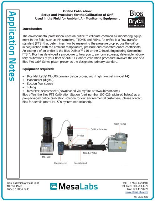
Equipment required:<br />
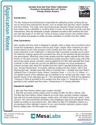
• Bios Met Lab® ML-500 primary piston prover, with High flow cell (model 44)<br />
• Manometer (digital)<br />
• Suction flow source<br />
• Tubing<br />
• Bios Excel spreadsheet (downloaded via myBios at www.biosint.com)<br />
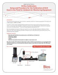
Bios offers <strong>the</strong> Bios FTS <strong>Calibration</strong> Station (part number 100-029, pictured below) as a<br />
pre-packaged orifice calibration solution <strong>for</strong> our environmental customers; please contact<br />
Bios <strong>for</strong> details (note: ML-500 system not included).<br />
Bios, a division of <strong>Mesa</strong> <strong>Labs</strong><br />
10 Park Place<br />
Butler, NJ USA 0745<br />
Tel: +1-973-492-8400<br />
Toll Free: 800.663.4977<br />
Fax: 973.492.8270<br />
www.<strong>Mesa</strong><strong>Labs</strong>.com<br />
Rev. 01.25.2013
Application Notes<br />
Installation:<br />
Step 1<br />
Place <strong>the</strong> orifice you wish to calibrate onto <strong>the</strong> holder mounted on <strong>the</strong> calibration station<br />
(or, “flow bench”).<br />
Step 2<br />
Place <strong>the</strong> adapter with <strong>the</strong> pressure tap onto <strong>the</strong> inlet of <strong>the</strong> orifice unit. If you’re using <strong>the</strong><br />
Bios Definer 110 orifice, unscrew its windscreen be<strong>for</strong>e installing <strong>the</strong> adapter.<br />
Step 3<br />
Your calibration station has a precision needle valve. Connect your tubing from one side of<br />
<strong>the</strong> needle valve to <strong>the</strong> orifice holder <strong>and</strong> on <strong>the</strong> o<strong>the</strong>r side to <strong>the</strong> pump.<br />
Step 4<br />
Place your ML-500 upstream of <strong>the</strong> orifice. Connect <strong>the</strong> ML-500’s outlet to <strong>the</strong> orifice’s inlet<br />
adapter.<br />
Operation:<br />
Step 1<br />
Power on your ML-500 <strong>and</strong> set it to take volumetric flow measurements.<br />
Step 2<br />
Without running gas flow to your ML-500, press its Read button. This will give you <strong>the</strong> ambient<br />
pressure condition, or Pamb. Record <strong>the</strong> Pamb in mmHg.<br />
Step 3<br />
From <strong>the</strong> manometer, connect its positive side to <strong>the</strong> pressure tap in <strong>the</strong> orifice inlet adapter<br />
<strong>and</strong> its negative side to <strong>the</strong> pressure tap in <strong>the</strong> orifice. This enables you to measure <strong>the</strong><br />
pressure drop (ΔP) across <strong>the</strong> orifice.<br />
Step 4<br />
Turn on <strong>the</strong> pump <strong>and</strong> begin taking flow measurements with your ML-500. Using <strong>the</strong> ML-<br />
500 flow measurements as reference, adjust <strong>the</strong> pump’s flow rate using <strong>the</strong> needle valve to<br />
<strong>the</strong> first desired flow rate calibration point.<br />
Step 5<br />
Step 5a, using <strong>the</strong> manometer to measure <strong>the</strong> pressure drop ΔP orifice<br />
: Cap <strong>the</strong> orifice pressure<br />
tap <strong>and</strong> connect <strong>the</strong> negative side to <strong>the</strong> pressure tap of <strong>the</strong> inlet adapter, while leaving<br />
<strong>the</strong> positive side open to ambient. This pressure drop is used to determine <strong>the</strong> orifice<br />
inlet pressure P orifice<br />
.<br />
OR<br />
Step 5b, using <strong>the</strong> DPI pressure indicator to measure pressure drop ΔP orifice<br />
: Connect a digital<br />
pressure indicator to <strong>the</strong> pressure tap of <strong>the</strong> inlet adapter to determine <strong>the</strong> orifice inlet<br />
pressure P orifice<br />
.<br />
Bios, a division of <strong>Mesa</strong> <strong>Labs</strong><br />
10 Park Place<br />
Butler, NJ USA 0745<br />
Tel: +1-973-492-8400<br />
Toll Free: 800.663.4977<br />
Fax: 973.492.8270<br />
www.<strong>Mesa</strong><strong>Labs</strong>.com
Application Notes<br />
Step 6<br />
Record <strong>the</strong> following data <strong>for</strong> entry into your Bios Excel spreadsheet. The spreadsheet calculates<br />
<strong>the</strong> m <strong>and</strong> b orifice calibration constants <strong>and</strong> displays <strong>the</strong> transfer orifice st<strong>and</strong>ard<br />
error at <strong>the</strong> calibration points with <strong>the</strong> currently calculated m <strong>and</strong> b values.<br />
• ΔP (pressure drop across <strong>the</strong> orifice, in inches H2O, as measured by <strong>the</strong> manometer)<br />
• ΔP orifice<br />
(pressure drop at <strong>the</strong> orifice inlet to ambient, in inches H2O, as measured by <strong>the</strong><br />
manometer)<br />
• T amb<br />
(orifice inlet temperature, in ºC, as measured by <strong>the</strong> ML-500)<br />
• QML (calibration flow rate, in liters per minute, as measured by <strong>the</strong> ML-500)<br />
Step 7<br />
Repeat Steps 1 through 6 at alternate flow rates within <strong>the</strong> orifice flow range (a minimum<br />
of seven calibration points is recommended).<br />
Application Notes:<br />
• This procedure is only valid in suction (vacuum) mode.<br />
• For best results, all calibrations should be per<strong>for</strong>med in a <strong>the</strong>rmally-stable environment.<br />
You can <strong>the</strong>rmallystabilize your orifice calibration <strong>setup</strong> by turning on <strong>the</strong> pump, adjusting<br />
<strong>the</strong> flow to <strong>the</strong> first calibration point, <strong>the</strong>n waiting at least 15 minutes be<strong>for</strong>e recording<br />
<strong>the</strong> first data point.<br />
• Your ML-500 should not be taking measurements while recording <strong>the</strong> pressure drop ΔP<br />
<strong>and</strong> orifice inlet pressure.<br />
• Use <strong>the</strong> shortest length of tubing possible between all system components <strong>for</strong> best accuracy.<br />
• The pump should not produce pressure variations.<br />
• The Bios spreadsheet per<strong>for</strong>ms a least square fit of <strong>the</strong> calibration data points. The<br />
calibration curve follows Y=mx+b, where “Y” represents <strong>the</strong> flow rate Qa, <strong>and</strong> where<br />
“x” represents √(ΔP*T amb<br />
/P amb<br />
) from <strong>the</strong> flow equation <strong>for</strong> <strong>the</strong> orifice: Qa=m*√(ΔP*T amb<br />
/<br />
P amb<br />
)+b.<br />
<strong>Mesa</strong>’s Butler, N.J. manufacturing facility (pictured above) is <strong>the</strong> only NVLAP accredited ISO 17025 laboratory<br />
serving <strong>the</strong> occupational health <strong>and</strong> safety industry. With <strong>the</strong> lowest gas flow measurement uncertainties of<br />
any commercial laboratory, <strong>Mesa</strong> provides you with <strong>the</strong> legal protections <strong>and</strong> peace of mind valued in today’s<br />
litigious business environment.<br />
Bios, a division of <strong>Mesa</strong> <strong>Labs</strong><br />
10 Park Place<br />
Butler, NJ USA 0745<br />
Tel: +1-973-492-8400<br />
Toll Free: 800.663.4977<br />
Fax: 973.492.8270<br />
www.<strong>Mesa</strong><strong>Labs</strong>.com