STIHL 020 T - Arbtalk
STIHL 020 T - Arbtalk
STIHL 020 T - Arbtalk

Create successful ePaper yourself
Turn your PDF publications into a flip-book with our unique Google optimized e-Paper software.
5.4 Ignition Module<br />
5.4.1 Ignition Timing<br />
• Use a pointed tool (awl or gimlet)<br />
to pierce the center of the other end<br />
of the ignition lead which screws<br />
into the module.<br />
The ignition module accommodates all<br />
the components required to control<br />
ignition timing. There are two electrical<br />
connections on the coil body:<br />
1. the high voltage output<br />
2. the connector tag for the short<br />
circuit wire<br />
Accurate testing of the ignition module<br />
is only possible with sophisticated test<br />
equipment. For this reason it is only<br />
necessary to carry out a spark test in<br />
the workshop. A new ignition module<br />
must be installed if no ignition spark is<br />
obtained (after checking that wiring<br />
and stop switch are in good condition).<br />
Ignition timing on the electronic<br />
(breakerless) magneto ignition<br />
system is fixed at 2.4 mm (0.094")<br />
B.T.D.C. at 8,000 r.p.m. and is not<br />
adjustable.<br />
However, in view of the permissible<br />
tolerances in the electronic<br />
circuit, it may vary between 2.0 and<br />
2.8 mm (0.08" and 0.11") B.T.D.C.<br />
at 8,000 r.p.m..<br />
Since there is no mechanical wear in<br />
these systems, ignition timing cannot<br />
get out of adjustment. However, an<br />
internal fault in the circuit can alter the<br />
switching point in such a way that a<br />
spark test will still show the system to<br />
be in order although timing is outside<br />
the permissible tolerance. This will<br />
impair engine starting and running<br />
behavior.<br />
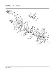
• Pull out the groomet at the<br />
ignition side.<br />
• Starting from the clutch side,<br />
thread the ignition lead (1)<br />
through the crankcase bores and<br />
the grommet (2).<br />
• Fit the grommet in the bore.<br />
Assembly of the remaining parts is a<br />
reversal of the disassembly sequence.<br />
<strong>STIHL</strong> <strong>020</strong> T 32