STIHL 020 T - Arbtalk
STIHL 020 T - Arbtalk
STIHL 020 T - Arbtalk

Create successful ePaper yourself
Turn your PDF publications into a flip-book with our unique Google optimized e-Paper software.
Service Manual<br />
<strong>020</strong> T Chain Saws<br />
This manual contains detailed<br />
descriptions of all repair and<br />
servicing procedures for <strong>020</strong> T<br />
chain saws.<br />
You should make use of the<br />
illustrated parts list while carrying<br />
out repair work. It shows the<br />
installed positions of the individual<br />
components and assemblies.<br />
Microfilmed parts lists are always<br />
more up to date than printed lists.<br />
Always use original <strong>STIHL</strong><br />
replacement parts.<br />
They can be identified by<br />
the <strong>STIHL</strong> part number, the<br />
STIHl logo<br />
and the <strong>STIHL</strong> parts symbol (<br />
The symbol may appear alone on<br />
small parts.<br />
A fault on the machine may have<br />
several causes. Consult the<br />
"Troubleshooting Charts" when<br />
tracing faults.<br />
Refer to the "Technical Information"<br />
bulletins for engineering changes<br />
which have been introduced since<br />
publication of this service manual.<br />
Technical information bulletins also<br />
supplement the parts list until a revised<br />
edition is issued.<br />
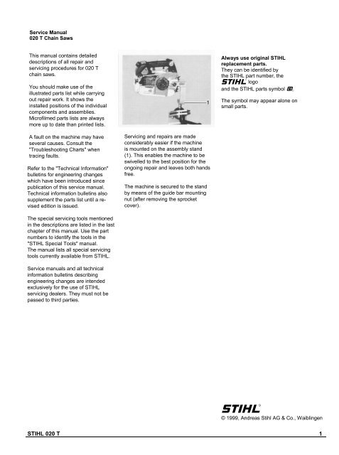
Servicing and repairs are made<br />
considerably easier if the machine<br />
is mounted on the assembly stand<br />
(1). This enables the machine to be<br />
swivelled to the best position for the<br />
ongoing repair and leaves both hands<br />
free.<br />
The machine is secured to the stand<br />
by means of the guide bar mounting<br />
nut (after removing the sprocket<br />
cover).<br />
The special servicing tools mentioned<br />
in the descriptions are listed in the last<br />
chapter of this manual. Use the part<br />
numbers to identify the tools in the<br />
"<strong>STIHL</strong> Special Tools" manual.<br />
The manual lists all special servicing<br />
tools currently available from <strong>STIHL</strong>.<br />
Service manuals and all technical<br />
information bulletins describing<br />
engineering changes are intended<br />
exclusively for the use of <strong>STIHL</strong><br />
servicing dealers. They must not be<br />
passed to third parties.<br />
STIHl<br />
© 1999, Andreas Stihl AG & Co., Waiblingen<br />
<strong>STIHL</strong> <strong>020</strong> T 1
CONTENTS<br />
1. Specifications 3<br />
1.1 Engine 3<br />
1.2 Fuel System 3<br />
1.3 Ignition System 4<br />
1.4 Cutting Attachment 4<br />
1.5 Special Accessories 4<br />
1.5.1 For User 4<br />
1.5.2 For Service 4<br />
1.6 Tightening Torques 5<br />
2. Troubleshooting<br />
Charts 6<br />
2.1 Clutch, Chain Drive,<br />
Chain Brake and<br />
Chain Tensioner 6<br />
2.2 Engine 7<br />
2.3 Ignition System 8<br />
2.4 Rewind Starter 9<br />
2.5 Chain Lubrication 9<br />
2.6 Fuel System 10<br />
3. Clutch, Chain Drive,<br />
Chain Brake and<br />
Chain Tensioner 12<br />
3.1 Disassembling Clutch 12<br />
3.2 Assembling Clutch 12<br />
3.3 Chain Sprocket 13<br />
3.4 Disassembling<br />
Chain Brake 13<br />
3.5 Assembling<br />
Chain Brake 14<br />
3.6 Chain Tensioner 15<br />
4. Engine 16<br />
4.1 Exhaust Muffler 16<br />
4.2 Leakage Test 16<br />
4.2.1 Preparations 17<br />
4.2.2 Pressure Test 17<br />
4.2.3 Vacuum Test 18<br />
4.3 Oil Seals 19<br />
4.4 Cylinder and Piston 20<br />
4.4.1 Removal 20<br />
4.4.2 Installation 21<br />
4.5 Piston Rings 23<br />
4.6 Crankcase 23<br />
4.6.1 Removing the<br />
Crankshaft 23<br />
4.6.2 Installing the<br />
Crankshaft 26<br />
5. Ignition System 29<br />
5.1 Spark Plug 29<br />
5.2 Spark Plug Terminal 31<br />
5.3 Ignition Lead 31<br />
5.4 Ignition Module 32<br />
5.4.1 Ignition Timing 32<br />
5.4.2 Removing and<br />
Installing 33<br />
5.5 Flywheel 33<br />
5.6 Ground Wire/<br />
Short Circuit Wire 34<br />
6. Rewind Starter 35<br />
6.1 Routine Maintenance 35<br />
6.2 Rope Rotor 35<br />
6.3 Replacing the<br />
Starter Rope 36<br />
6.4 Replacing the<br />
Rewind Spring 36<br />
6.5 Tensioning the<br />
Rewind Spring 37<br />
6.6 Pawl 38<br />
6.7 Starter Rope<br />
Guide Bush 38<br />
7. AV Handle System 39<br />
8. Master Control/<br />
Handle System 40<br />
8.1 Master Control Lever 40<br />
8.2 Choke/Throttle<br />
Rods 40<br />
8.3 Interlock Lever/<br />
Throttle Trigger 41<br />
8.4 Switch Shaft 41<br />
8.5 Contact Springs 41<br />
8.6 Double Lever<br />
(Choke/Throttle) 42<br />
8.7 Front Handle 42<br />
8.8 Handle Housing 43<br />
9. Chain Lubrication 44<br />
9.1 Suction Hose/<br />
Pickup Body 44<br />
9.2 Vent Valve 45<br />
9.3 Oil Pump 46<br />
9.3.1 Removing and<br />
Installing 46<br />
9.3.2 Servicing 46<br />
10. Fuel System 47<br />
10.1 Air Filter 47<br />
10.2 Carburetor 47<br />
10.2.1 Removing and<br />
Installing 47<br />
10.2.2 Leakage Testing 48<br />
10.2.3 Servicing 48<br />
10.3 Carburetor<br />
Adjustment 53<br />
10.4 Pickup Body/<br />
Fuel Hose 54<br />
10.5 Tank Vent 55<br />
10.6 Tank Housing 55<br />
11. Special Servicing<br />
Tools and Aids 57<br />
11.1 Special Servicing<br />
Tools 57<br />
11.2 Servicing Aids 58<br />
<strong>STIHL</strong> <strong>020</strong> T 2
1. SPECIFICATIONS<br />
1.1 Engine<br />
<strong>STIHL</strong> single-cylinder two-stroke engine with special<br />
impregnated cylinder bore<br />
Displacement:<br />
Bore:<br />
Stroke:<br />
Compression ratio:<br />
Power output:<br />
Max. torque:<br />
35.2 cm 3 (2.15 cu.in)<br />
40 mm (1.57 in)<br />
28 mm (1.10 in)<br />
7.41:1<br />
1.6 kW (2.2 bhp)<br />
1.8 Nm (1.3 Ib.ft)<br />
at 7,500 r.p.m.<br />
Max. permissible engine<br />
speed with bar and chain:<br />
Mean idle speed:<br />
Bearings:<br />
Piston pin diameter:<br />
Connecting rod length:<br />
Rewind starter:<br />
Reserve pull on rope rotor:<br />
Starter rope:<br />
Clutch:<br />
Diameter:<br />
Clutch engages at:<br />
Crankcase leakage<br />
test<br />
at gauge pressure:<br />
under vacuum:<br />
14,000 r.p.m.<br />
2,800 r.p.m.<br />
Crankshaft supported in heavyduty<br />
roller bearings, needle<br />
cages on small and big ends<br />
9 mm (0.35 in)<br />
49 mm (1.93 in)<br />
Pawl system<br />
min. 1/2 turn<br />
3.0 mm (0.12 in) dia., 800 mm<br />
(31.5 in) long<br />
Centrifugal clutch without linings<br />
66 mm (2.60 in)<br />
3,900 r.p.m.<br />
0.5 bar (7.25 psi)<br />
0.5 bar (7.25 psi)<br />
1.2 Fuel System Carburetor:<br />
Standard setting<br />
High speed adjusting screw H:<br />
Low speed adjusting screw L:<br />
Carburetor leakage test<br />
at gauge pressure:<br />
Fuel tank capacity:<br />
Octane number:<br />
Fuel mixture:<br />
Mix ratio:<br />
Air filter:<br />
Diaphragm carburetor<br />
Back off approx. 1 turn<br />
Back off approx. 1 turn<br />
0.4 bar (5.8 psi)<br />
0.37 I (0.8 US pt)<br />
mind. 90 RON (USA/CAN: pump<br />
octane min. 87 unleaded)<br />
Regular brand-name gasoline<br />
and two-stroke engine oil<br />
50:1 with Stihl two-stroke<br />
engine oil<br />
25:1 with other brand-name<br />
two-stroke, air-cooled<br />
engine oils<br />
Dual-ply synthetic fabric<br />
or flocked wire mesh element<br />
and foam element<br />
<strong>STIHL</strong> <strong>020</strong> T 3
1.3 Ignition System<br />
Type:<br />
Air gap:<br />
Ignition timing:<br />
Advance angle:<br />
Spark plug (suppressed):<br />
Electrode gap:<br />
Spark plug thread:<br />
Length of thread:<br />
Heat range:<br />
Electronic magneto ignition<br />
(breakerless) with integral<br />
trigger unit<br />
0.25 mm (0.010 in)<br />
2.0 - 2.8 mm B.T.D.C.<br />
at 8,000 r.p.m.<br />
24.7 -32.5° B.T.D.C.<br />
at 8,000 r.p.m.<br />
Bosch WSR 6 F or NGK BPMR 7 A<br />
0.5 mm (0.<strong>020</strong> in)<br />
M14x1.25<br />
9.5 mm (0.37 in)<br />
200<br />
1.4 Cutting Attachment<br />
Guide bars:<br />
Bar tail:<br />
Bar lengths:<br />
Oilomatic chain:<br />
Chain sprockets:<br />
Chain speed:<br />
Chain lubrication:<br />
Oil feed rate (adjustable):<br />
Oil tank capacity:<br />
Rollomatic<br />
3005<br />
30, 35, 40 and 45 cm<br />
(12, 14, 16 and 18 in)<br />
3/8" (9.32 mm) Picco-Micro<br />
Optional:<br />
1/4" (6.35 mm) Rapid-Micro<br />
6-tooth spur sprocket for 3/8" Picco<br />
Optional:<br />
7-tooth for 3/8" Picco<br />
8-tooth for 1/4"<br />
18.6 m/s (61 ft/sec) at 10,000 r.p.m.<br />
(with 6-tooth 3/8" P sprocket)<br />
Speed-controlled reciprocating<br />
oil pump, no oil feed at<br />
idle speed. Additional manual<br />
oil flow adjustment<br />
4.0 - 10.5 cm 3 /min<br />
0.14 -0.36 fl.oz/min) at 10,000 r.p.m.<br />
0.24 I (0.5 US pt)<br />
1.5 Special Accessories<br />
1.5.1 For User<br />
1.5.2 For Service Shop<br />
<strong>STIHL</strong> repair kit<br />
7-tooth 3/8" P spur sprocket<br />
8-tooth 1/4" spur sprocket<br />
Elastostart<br />
Air filter (flocked)<br />
Carburetor parts kit<br />
Gasket kit<br />
Spur gear/tensioning screw kit<br />
1129 900 5000<br />
1129 640 2050<br />
1129 640 2051<br />
1128 190 3400<br />
1129 120 1606<br />
1129 007 1060<br />
1129 007 1050<br />
1129 007 1000<br />
<strong>STIHL</strong> <strong>020</strong> T 4
1.6 Tightening Torques<br />
Plastoform screws are used for polymer components and "DG" screws for lightmetal components. These screws form a<br />
permanent thread when they are installed for the first time. They can be removed and installed as often as necessary<br />
without detrimentally affecting the strength of the screwed assembly, providing the specified tightening torque is<br />
observed. For this reason it is essential to use a torque wrench.<br />
Fastener<br />
Thread size<br />
For component<br />
Torque<br />
Nm<br />
Ibf.ft<br />
Remarks<br />
Spline screw<br />
Spline screw<br />
Spline screw<br />
Spline screw<br />
Spline screw<br />
Spline screw<br />
Spline screw<br />
Spline screw<br />
Spline screw<br />
Spline screw<br />
Spline screw<br />
Spline screw<br />
Spline screw<br />
Spline screw<br />
Spline screw<br />
Spline screw<br />
Spline screw<br />
Spline screw<br />
Spline screw<br />
Spline screw<br />
Nut<br />
Collar nut<br />
Collar nut<br />
Screw assembly<br />
Spline screw<br />
Spline screw<br />
Screw<br />
Screw<br />
IS-P 4x14<br />
IS-P 4x14<br />
IS-P 4x14<br />
IS-DG 4x15<br />
IS-M 5x12<br />
IS-M 5x20<br />
IS-DG 4x15<br />
IS-M 4x12<br />
IS-M 5x12<br />
IS-P 6x19<br />
IS-P 5x20<br />
IS-M 4x16<br />
IS-P 4x10<br />
IS-M 4x12<br />
IS-M 4x12<br />
IS-M 4x16<br />
IS-M 4x16<br />
IS-M 4x20<br />
IS-M 5x12<br />
IS-M 5x16<br />
M 5<br />
M 8x1<br />
M 8x1 L<br />
M 14x1.25<br />
IS-P 5<br />
IS-M 4x16<br />
IS-P 4x14<br />
IS-P 6x21.5<br />
IS-P 4x10<br />
Chain catcher<br />
Insert, chain brake<br />
Handle molding<br />
Muffler<br />
Spiked bumper/crankcase<br />
Muffler to cylinder<br />
Insert<br />
Oil pump<br />
Annular buffer/front handle<br />
Ring on housing<br />
Fan cover/tank housing<br />
Fan cover/crankcase<br />
Segment/fan cover<br />
Cover/chain tensioner<br />
Cover/oil pump<br />
Crankcase<br />
Tank housing<br />
Ignition module<br />
Bar mounting flange/crankcase<br />
Cylinder<br />
Carburetor<br />
Flywheel<br />
Clutch<br />
Spark plug<br />
Annular buffer/handle housing<br />
Annular buffer, front<br />
Annular buffer, rear<br />
Front handle/handle housing<br />
Control lever/switch shaft<br />
1.7 1.25<br />
3.2 2.4<br />
1.6 1.2<br />
4.0 3.0<br />
7.0 5.2<br />
11.5 8.5<br />
3.2 2.4<br />
3.5 2.6<br />
6.0 4.4<br />
7.0 5.2<br />
4.0 3.0<br />
4.0 3.0<br />
3.2 2.4<br />
2.4 1.8<br />
3.0 2.2<br />
5.5 4.0<br />
5.3 3.9<br />
6.5 4.8<br />
7.0 5.2<br />
11.5 8.5<br />
3.3 2.5<br />
25.0 18.5<br />
32.5 24.0<br />
25.0 18.5<br />
4.0 3.0<br />
5.5 4.0<br />
1.7 1.25<br />
5.5 4.0<br />
1.3 0.95<br />
1)<br />
1)<br />
1)<br />
2)<br />
1)<br />
1)<br />
1)<br />
2) 3)<br />
2)<br />
1)<br />
1)<br />
1)<br />
1)<br />
Use the following procedure when refitting a P or DG screw in an existing thread:<br />
- Place the screw in the hole and rotate it counterclockwise until it drops down slightly.<br />
- Tighten the screw clockwise to the specified torque.<br />
This procedure ensures that the screw engages properly in the existing thread and does not form a new thread.<br />
1) Torque may be reduced by approx. 1 Nm (0.7 Ibf.ft) when refitting a screw in an existing thread<br />
2) Screw must be secured with adhesive 0786 111 1101 (Loctite 243).<br />
3) A washer must be fitted under the screw head.<br />
Note: Screws secured with adhesive are easier to release if the adhesive is heated first with a hot air blower (hair dryer).<br />
Exercise caution on polymer components.<br />
<strong>STIHL</strong> <strong>020</strong> T 5
2. TROUBLESHOOTING CHARTS<br />
2.1 Clutch, Chain Drive, Chain Brake and Chain Tensioner<br />
Condition<br />
Cause<br />
Remedy<br />
Saw chain turns at idle speed<br />
Engine speed too high<br />
Spring hooks broken<br />
Readjust at idle speed<br />
adjusting screw<br />
(counterclockwise)<br />
Fit new springs<br />
Loud noises<br />
Clutch springs stretched or<br />
fatigued<br />
Needle cage damaged<br />
Clutch shoe retainer broken<br />
Clutch shoes and carrier<br />
worn<br />
Replace all clutch springs<br />
Fit new needle cage<br />
Fit new retainer<br />
Fit new clutch<br />
Chain sprocket wears rapidly<br />
Chain not properly tensioned<br />
Tension chain as specified<br />
Chain wears rapidly<br />
Chain not properly tensioned<br />
Poor chain lubrication<br />
Worn chain sprocket<br />
Tension chain as specified<br />
Check chain lubrication and<br />
rectify problem<br />
Fit new sprocket<br />
Chain does not stop immediately<br />
when brake is activated<br />
Brake spring broken<br />
Brake band stretched or<br />
broken<br />
Fit new brake spring<br />
Fit new brake band<br />
<strong>STIHL</strong> <strong>020</strong> T 6
2.2 Engine<br />
Always check and, if necessary, repair the following parts before looking for faults on the engine:<br />
- Air filter<br />
- Fuel system<br />
- Carburetor<br />
- Ignition system<br />
Condition<br />
Cause<br />
Remedy<br />
Engine does not start easily, stalls<br />
at idle speed, but operates<br />
normally at full throttle<br />
Oil seals in crankcase<br />
damaged<br />
Manifold leaking<br />
Cylinder base gasket leaking<br />
Crankcase damaged (cracks)<br />
Replace oil seals<br />
Seal or replace manifold<br />
Replace gasket<br />
Replace crankcase<br />
Engine does not deliver full<br />
power or runs erratically<br />
Secondary air seepage through<br />
poorly mounted or faulty manifold<br />
Piston rings leaking or<br />
broken<br />
Muffler carbonized<br />
Mount manifold correctly or<br />
replace<br />
Fit new piston rings<br />
Clean muffler (inlet and<br />
exhaust), replace spark<br />
arresting screen (if fitted)<br />
Engine overheating<br />
Insufficient cylinder cooling.<br />
Air inlets in fan housing<br />
blocked or cooling fins on<br />
cylinder very dirty<br />
Thoroughly clean all cooling air<br />
openings and cylinder fins<br />
<strong>STIHL</strong> <strong>020</strong> T 7
2.3 Ignition System<br />
Warning: Exercise extreme caution while carrying out maintenance and repair work on the ignition system.<br />
The high voltages which occur can cause serious or fatal accidents!<br />
Spark plug terminal firmly seated on spark plug?<br />
yes<br />
no<br />
Remove spark plug.<br />
Is it in good condition?<br />
yes<br />
Press terminal firmly onto spark<br />
plug and fit spring if necessary.<br />
no<br />
Clean spark plug and reset electrode gap.<br />
Does spark test produce powerful spark?<br />
no<br />
Faulty insulation on ignition<br />
lead or short circuit wire?<br />
yes<br />
no<br />
Replace faulty ignition lead of short<br />
circuit wire. Repair contact spring.<br />
Insert screwdriver in place of spark plug in spark plug<br />
terminal and hold about 4 mm (1/8") away from<br />
ground. Sparkover?<br />
no<br />
yes<br />
Is air gap correct?<br />
yes<br />
Fit new spark plug.<br />
no<br />
Adjust air gap (0.25 mm/0.010 in).<br />
Is spark test positive?<br />
Does flywheel appear to<br />
be in good condition?<br />
no<br />
yes<br />
no<br />
Use ohmmeter to check ignition lead<br />
for break. If break is detected, replace<br />
ignition lead. Does spark test now<br />
produce sparkover?<br />
no<br />
Fit new flywheel.<br />
Is spark test positive?<br />
no<br />
Replace ignition module. Does engine<br />
now run after positive spark test?<br />
no<br />
Ignition system in order.<br />
Look for fault in fuel system and<br />
carburetor.<br />
<strong>STIHL</strong> <strong>020</strong> T 8
2.4 Rewind Starter<br />
Condition<br />
Cause<br />
Remedy<br />
Starter rope broken<br />
Rope pulled out too vigorously<br />
as far as stop or over edge –<br />
i.e. not vertically<br />
Normal wear<br />
Fit new starter rope<br />
Fit new starter rope<br />
Rewind spring broken<br />
Spring overtensioned –<br />
no reserve when rope is<br />
fully extended<br />
Very dirty or corroded<br />
Fit new rewind spring<br />
Fit new rewind spring<br />
Starter rope can be pulled out<br />
almost without resistance<br />
(crankshaft does not turn)<br />
Guide peg on pawl or pawl<br />
itself is worn<br />
Spring clip fatigued<br />
Fit new pawl<br />
Fit new spring clip<br />
Starter rope is difficult to pull<br />
and rewinds very slowly<br />
Starter mechanism is very<br />
dirty (dusty conditions)<br />
Lubricating oil on rewind<br />
spring becomes viscous<br />
at very low outside temperatures<br />
(spring windings<br />
stick together)<br />
Thoroughly clean complete<br />
starter mechanism<br />
Apply a few drops of kerosine<br />
(paraffin) to spring, then pull rope<br />
carefully several times until normal<br />
action is restored<br />
2.5 Chain Lubrication<br />
Important: In the event of trouble with chain lubrication system, always investigate the other possible sources of faults<br />
before disassembling the oil pump.<br />
Condition<br />
Chain receives no oil<br />
Cause<br />
Oil tank empty<br />
Oil inlet hole in guide bar is<br />
blocked<br />
Intake hose or pickup body<br />
(strainer) clogged or intake<br />
hose ruptured<br />
Valve in oil tank blocked<br />
Teeth on pump piston and/or<br />
worm worn<br />
Remedy<br />
Fill up with oil<br />
Clean oil inlet hole<br />
Wash intake hose and pickup body<br />
(strainer) in white spirit and blow out<br />
with compressed air; replace if<br />
necessary<br />
Clean or replace valve<br />
Fit new pump piston and/or<br />
new worm<br />
<strong>STIHL</strong> <strong>020</strong> T 9
Condition<br />
Cause<br />
Remedy<br />
Machine losing chain oil<br />
Bore in pump housing<br />
worn<br />
Fit new pump housing<br />
Oil pump delivers too<br />
little oil<br />
Control screw and/or control<br />
edge on pump piston worn<br />
Bore in pump housing<br />
Fit new control screw and/or<br />
pump piston<br />
Fit new pump housing<br />
worn<br />
2.6 Fuel System<br />
Condition<br />
Cause<br />
Remedy<br />
Carburetor floods;<br />
engine stalls<br />
Inlet needle not sealing.<br />
Foreign matter in valve seat or<br />
cone damaged<br />
Inlet control lever sticking on<br />
spindle<br />
Helical spring not located on<br />
nipple of inlet control lever<br />
Perforated disc on diaphragm is<br />
deformed and presses constantly<br />
against inlet control lever Inlet<br />
control lever too high (relative to<br />
design position)<br />
Remove and clean or replace<br />
inlet needle, clean fuel tank,<br />
pickup body and fuel line if<br />
necessary<br />
Free off inlet control lever<br />
Remove inlet control lever<br />
and refit correctly<br />
Fit new metering diaphragm<br />
Set inlet control lever flush with<br />
bottom of metering chamber<br />
Poor acceleration<br />
Idle jet "too lean"<br />
Main jet "too lean"<br />
Inlet control lever too low<br />
(relative to design position)<br />
Inlet needle sticking to valve<br />
seat<br />
Connecting bore to atmosphere<br />
blocked<br />
Back off low speed adjusting<br />
screw slightly (see Carburetor<br />
Adjustment)<br />
Back off high speed adjusting<br />
screw slightly (see Carburetor<br />
Adjustment)<br />
Set inlet control lever flush with<br />
bottom of metering chamber<br />
Remove inlet needle, clean and<br />
refit<br />
Clean bore<br />
<strong>STIHL</strong> <strong>020</strong> T 10
Condition<br />
Cause<br />
Remedy<br />
Diaphragm gasket leaking<br />
Metering diaphragm damaged or<br />
shrunk<br />
Fit new diaphragm gasket<br />
Fit new metering diaphragm<br />
Engine will not idle,<br />
idle speed too high<br />
Throttle shutter opened too wide<br />
Reset idle speed adjusting screw<br />
by idle speed adjusting screw<br />
correctly<br />
Engine stalls at idle speed<br />
Idle jet bores or ports<br />
blocked<br />
Idle jet "too rich"<br />
Setting of idle speed<br />
adjusting screw incorrect<br />
- throttle shutter completely<br />
closed<br />
Small plastic plate in valve<br />
jet does not close<br />
Clean jet bores and ports<br />
with compressed air<br />
Screw down low speed adjusting<br />
screw slightly<br />
(see Carburetor Adjustment)<br />
Set idle speed adjusting<br />
screw correctly<br />
Clean or renew valve jet<br />
Engine speed drops quickly under<br />
load - low power<br />
Air filter dirty<br />
Tank vent faulty<br />
Leak in fuel line between tank<br />
and fuel pump<br />
Pump diaphragm damaged or<br />
fatigued<br />
Main jet bores or ports<br />
blocked<br />
Fuel pickup body dirty<br />
Fuel strainers dirty<br />
Clean air filter<br />
Clean or replace tank vent if<br />
necessary<br />
Seal or renew connections<br />
and fuel line<br />
Fit new pump diaphragm<br />
Clean bores and ports<br />
Clean pickup body, fit new<br />
filter<br />
Clean fuel strainers<br />
See also 2.2<br />
<strong>STIHL</strong> <strong>020</strong> T 11
3. CLUTCH, CHAIN DRIVE, CHAIN BRAKE AND CHAIN TENSIONER<br />
3.1 Disassembling Clutch 3.2 Assembling Clutch<br />
Troubleshooting chart - see 2.1.<br />
• Disengage the chain brake by<br />
pulling the hand guard toward<br />
the front handle.<br />
• Unscrew collar nut (1) and<br />
remove the sprocket cover.<br />
• Unscrew the clutch from the<br />
stub of the crankshaft.<br />
Caution: Clutch has a left-hand<br />
thread.<br />
• Slip the retainers (1) onto the<br />
clutch shoes (2) so that the<br />
narrow side is next to the series<br />
number, e.g. 1129 (3).<br />
• Pull terminal (1) off the spark plug<br />
(2). Unscrew the spark plug.<br />
• Use assembly hook (2) to remove<br />
all the clutch springs (1).<br />
• Pull the clutch shoes off the<br />
carrier.<br />
• Pull the retainers off the clutch<br />
shoes.<br />
• Clean all parts and stub of<br />
crankshaft in white spirit.<br />
Replace any damaged or worn<br />
parts.<br />
• Fit the clutch shoes over the arms<br />
(1) of the clutch carrier so that the<br />
series number is on the same side<br />
as the larger hexagon (2).<br />
• Set piston to bottom dead center.<br />
• Push the locking strip (1), thicker<br />
end (2) first, into spark plug hole<br />
and then rotate it 180°.<br />
• Clamp the clutch, e.g. one shoe,<br />
in a vise.<br />
<strong>STIHL</strong> <strong>020</strong> T 12
3.3 Chain Sprocket 3.4 Disassembling<br />
Chain Brake<br />
• Attach one end of each spring<br />
(1) to the clutch shoes.<br />
• Use the assembly hook (2) to<br />
attach the other ends of the<br />
springs and press them firmly<br />
into the clutch shoes with one<br />
finger.<br />
• Remove clutch - see 3.1.<br />
• Pull chain sprocket off the crankshaft.<br />
• Remove sprocket cover –<br />
see 3.1.<br />
• Engage brake band by pushing<br />
the hand guard away from the<br />
sprocket cover.<br />
• Screw clutch onto crankshaft and<br />
torque down to 32.5 Nm (24 Ibf.ft).<br />
• Remove locking strip from<br />
cylinder. Install spark plug and<br />
torque down to 25 Nm (18.5 Ibf.ft).<br />
Refit terminal.<br />
• Take the needle cage out of the<br />
sprocket.<br />
• Clean stub of crankshaft.<br />
Wash needle cage in clean white<br />
spirit and lubricate with grease<br />
- see 11.2. Replace damaged<br />
needle cage.<br />
• The chain sprocket must engage<br />
the worm properly.<br />
• Install clutch - see 3.2.<br />
• Take out screws (1).<br />
• Remove the segment (2).<br />
• Fit sprocket cover so that pin (1)<br />
engages hole (2).<br />
• Fit the collar nut.<br />
• Carefully pry the brake spring (1)<br />
off the anchor pin and unhook it<br />
from the bell crank (2).<br />
<strong>STIHL</strong> <strong>020</strong> T 13
3.5 Assembling Chain Brake<br />
• Take the brake band (1) out of the<br />
sprocket cover and detach it from<br />
the bell crank (2) at the same time.<br />
• Fit lever with pivot pin and press it<br />
home as far as stop.<br />
• Slide bell crank into end of hand<br />
guard. The long arm (1) of the<br />
bell crank must point to the hole<br />
(2)<br />
• Ease the hand guard (1) and bell<br />
crank (2) off the pivot pins.<br />
• Pull the bell crank out of the<br />
hand guard and then take the<br />
hand guard out of the sprocket<br />
cover.<br />
• Fit flat spring (1) in position.<br />
• Locate the hand guard and bell<br />
crank on the pivot pins.<br />
• Now press the flat spring (1)<br />
down and push the hand guard<br />
and bell crank fully home.<br />
• Remove lever (1) with pivot pin<br />
and flat spring (2).<br />
• Inspect parts. Replace any worn<br />
or damaged parts.<br />
• Fit hand guard in the sprocket<br />
cover.<br />
• Attach brake band to the bell<br />
crank.<br />
<strong>STIHL</strong> <strong>020</strong> T 14
3.6 Chain Tensioner<br />
• Press the brake band into the<br />
sprocket cover.<br />
Important: Coat sliding and bearing<br />
points of chain brake with Molykote<br />
grease - see 11.2.<br />
Do not lubricate the brake band.<br />
• Remove chain sprocket cover –<br />
see 3.1.<br />
• Remove screw from cover.<br />
• Pull the spur gear (1) out of the<br />
cover (2).<br />
• Hook the brake spring onto the<br />
bell crank.<br />
• Take out the complete chain<br />
tensioner.<br />
• Pull off the tensioner slide (1).<br />
• Remove the adjusting screw (2).<br />
• Inspect the teeth on the spur gear<br />
and adjusting screw. If the teeth are<br />
damaged, replace both parts.<br />
Reverse the above sequence to<br />
install the chain tensioner.<br />
Note: Coat teeth of adjusting<br />
screw and spur gear with grease,<br />
see 11.2, before refitting.<br />
• Use the assembly tool (2) to attach<br />
the brake spring (1) to the anchor<br />
pin.<br />
• Fit the segment and tighten<br />
screws to 3.2 Nm (2.4 Ibf.ft).<br />
• Remove the thrust pad (1).<br />
• Rotate the spur gear (2) to unscrew<br />
the adjusting screw (3) fully from the<br />
tensioner slide (4).<br />
<strong>STIHL</strong> <strong>020</strong> T 15
4. ENGINE<br />
4.1 Exhaust Muffler<br />
4.2 Leakage Test<br />
Troubleshooting chart - see 2.2.<br />
• Remove sprocket cover –<br />
see 3.1.<br />
• Take out the screw (1).<br />
• Remove the cover (2).<br />
• Take out the screws.<br />
• Lift lower casing away from<br />
upper casing.<br />
Defective oil seals and gaskets or<br />
cracks in castings are the usual<br />
causes of leaks. Such faults allow<br />
supplementary air to enter the<br />
engine and thus upset the fuel-air<br />
mixture.<br />
This makes adjustment of the<br />
prescribed idle speed difficult, if<br />
not impossible.<br />
Moreover, the transition from idle<br />
speed to part or full throttle is not<br />
smooth.<br />
The crankcase can be checked<br />
thoroughly for leaks with the .<br />
carburetor and crankcase tester<br />
and the vacuum pump.<br />
• Remove mounting screws from<br />
underside of machine.<br />
• Take out the screw.<br />
• Remove baffle from guide in<br />
upper casing.<br />
• Clean baffle or fit a new one.<br />
Note: If baffle is equipped with<br />
spark arresting screen, make sure<br />
the spark arresting screen is refitted.<br />
Reassemble in the reverse<br />
sequence.<br />
Note: Install a new gasket.<br />
Tighten screws of upper casing to<br />
4 Nm (3 Ibf.ft) and muffler mounting<br />
screws to 11.5 Nm (8.5 Ibf.ft).<br />
• Pull out the muffler.<br />
• Remove the gasket.<br />
<strong>STIHL</strong> <strong>020</strong> T 16
4.2.1 Preparations<br />
4.2.2 Pressure Test<br />
• Remove the muffler – 4.1.<br />
• Set the piston to top dead center<br />
(T.D.C.). This can be checked<br />
through the exhaust port.<br />
• Fit flange (1) with sleeves (2)<br />
and screws (3) on cylinder<br />
exhaust port. Do not tighten<br />
down yet.<br />
• Slide the sealing plate (4)<br />
between the flange and cylinder<br />
and tighten down the mounting<br />
screws.<br />
Note: The sealing plate must<br />
completely fill the space between<br />
the two mounting screws.<br />
• Remove the carburetor –<br />
see 10.2.1.<br />
• Check that washer (1) and<br />
sleeve (2) are in position.<br />
• Connect tester's pressure hose to<br />
nipple on test flange.<br />
• Make sure the spark plug is<br />
properly tightened down.<br />
• Remove screw (1) from the test<br />
flange (2).<br />
• Close the vent screw (1) on the<br />
rubber bulb.<br />
• Use rubber bulb to pump air into<br />
the crankcase until the gauge<br />
indicates a pressure of 0.5 bar<br />
(7.25 psi). If this pressure remains<br />
constant for at least 20 seconds,<br />
the crankcase is airtight.<br />
If the flange has only three holes,<br />
drill a fourth hole as shown in the<br />
drawing.<br />
• Fit the test flange on the<br />
carburetor studs.<br />
• Fit nuts (1) and tighten down<br />
firmly.<br />
<strong>STIHL</strong> <strong>020</strong> T 17
4.2.3 Vacuum Test<br />
• However, if the indicated pressure<br />
drops, the leak must be located and<br />
the faulty part replaced.<br />
Note: To find the leak, coat the<br />
suspect area with oil and<br />
pressurize the crankcase again.<br />
Bubbles will appear if a leak exists.<br />
• Carry out the vacuum test –<br />
see 4.2.3.<br />
• After finishing the test, open the<br />
vent screw and disconnect the<br />
hose.<br />
• Remove the test flange and refit<br />
the carburetor - see 10.2.<br />
• Remove the flange and sealing<br />
plate.<br />
• Install the muffler - see 4.1.<br />
Oil seals tend to fail when subjected<br />
to a vacuum, i.e. the sealing<br />
lip lifts away from the crankshaft<br />
during the piston's induction stroke<br />
because there is no internal<br />
counterpressure.<br />
An additional test can be carried<br />
out with the vacuum pump to<br />
detect this kind of fault.<br />
The preparations for this test are<br />
the same as for the pressure test –<br />
see 4.2.1.<br />
• Connect the vacuum pump's suction<br />
hose to test flange nipple.<br />
• Make sure spark plug is tight.<br />
Note: When you release the pump<br />
piston, the non-return valve automatically<br />
seals the suction hose.<br />
If the vacuum reading remains<br />
constant, or rises to no more than<br />
0.4 bar (5.8 psi) within 20 seconds,<br />
it can be assumed that the oil seals<br />
are in good condition.<br />
However, if the pressure continues<br />
to rise (reduced vacuum in the<br />
crankcase), the oil seals must be<br />
replaced, even if no leaks were<br />
detected in the pressure test.<br />
• Remove the test flange and refit<br />
the carburetor - see 10.2.<br />
• Remove the flange and sealing<br />
plate.<br />
• Install the muffler - see 4.1.<br />
• Pull out the pump piston several<br />
times until the gauge indicates a<br />
vacuum of 0.5 bar (7.25 psi).<br />
<strong>STIHL</strong> <strong>020</strong> T 18
4.3 Oil Seals<br />
It is not necessary to disassemble<br />
the complete crankcase if only the oil<br />
seals have to be replaced.<br />
Clutch side:<br />
• Remove the oil pump - see 9.3.1.<br />
• Rotate the angled ends on the<br />
hooks (1) of the puller (3) so that<br />
they are in line with the arms (2).<br />
• Apply the puller, rotate hooks 90°<br />
(angled ends must locate under the<br />
oil seal). Clamp the arms and pull<br />
the oil seal out.<br />
Important: Take special care not to<br />
damage crankshaft stub.<br />
• Clean sealing face on crankshaft<br />
stub with standard commercial,<br />
solvent-based degreasant containing<br />
no chlorinated or halogenated<br />
hydrocarbons - see 11.2.<br />
• Pack cavity between sealing lip<br />
and oil seal with grease –<br />
see 11.2.<br />
• Push the oil seal (closed side<br />
facing crankcase) over the<br />
crankshaft and use press sleeve<br />
(1) to press it home.<br />
• Install the oil pump - see 9.3.1.<br />
Ignition side:<br />
• Remove the flywheel - see 5.5.<br />
• Apply the puller as at the clutch<br />
side and pull out the oil seal.<br />
Important: Take special care not to<br />
damage crankshaft stub.<br />
• Clean sealing face on crankshaft<br />
stub with standard commercial,<br />
solvent-based degreasant containing<br />
no chlorinated or halogenated<br />
hydrocarbons - see 11.2.<br />
• Pack cavity between sealing lip<br />
and oil seal with grease –<br />
see 11.2.<br />
• Slip the installing sleeve (1) over<br />
the crankshaft. The slot must<br />
locate on the Woodruff key (2).<br />
• Push the oil seal over the installing<br />
sleeve (closed side of seal facing<br />
crankcase) and use press sleeve (1)<br />
to press it home.<br />
• Remove the installing sleeve.<br />
• Fit the flywheel - see 5.5.<br />
<strong>STIHL</strong> <strong>020</strong> T 19
4.4 Cylinder and Piston<br />
4.4.1 Removal<br />
Always check and, if necessary, repair<br />
the fuel system, carburetor, air filter<br />
and ignition system before looking for<br />
faults on the engine.<br />
• Remove the tank housing -<br />
see 10.6.<br />
• Remove the spark plug.<br />
• Pull the manifold (1) off the<br />
intake port.<br />
• Inspect the cylinder and replace<br />
it if necessary.<br />
Note: If a new cylinder has to be<br />
installed, always fit the matching<br />
piston. Replacement cylinders are<br />
only supplied complete with piston<br />
for this reason.<br />
Important: Before removing the<br />
piston, decide whether or not the<br />
crankshaft has to be removed as well.<br />
To remove the flywheel, block the<br />
crankshaft by sliding the wooden<br />
assembly block between the piston<br />
and crankcase.<br />
• Now use the assembly drift (2) to<br />
push the piston pin (1) out of the<br />
piston.<br />
Note: If the piston pin is stuck, tap the<br />
end of the drift lightly with a hammer<br />
if necessary.<br />
Important: Hold the piston steady<br />
during this process to ensure that no<br />
jolts are transmitted to the connecting<br />
rod.<br />
• Remove piston and take the<br />
needle cage out of the connecting<br />
rod.<br />
• Release and unscrew the four<br />
cylinder base screws through the<br />
holes in the cylinder fins.<br />
• Pull the cylinder off the piston.<br />
• Remove the cylinder gasket.<br />
• Use a scriber or similar tool to<br />
ease the hookless snap rings out<br />
of the grooves in the piston<br />
bosses.<br />
• Inspect piston rings and replace if<br />
necessary - see 4.5.<br />
<strong>STIHL</strong> <strong>020</strong> T 20
4.4.2 Installation<br />
• Thoroughly clean the gasket<br />
seating surface (1).<br />
• Lubricate the needle cage (2) with<br />
oil and fit it in the small end.<br />
• Fit the piston pin (1) on the<br />
assembly drift (2) and slide it into<br />
the piston (the pin slides home<br />
easily if the piston is hot).<br />
• Push the large slotted diameter<br />
of the sleeve over the magnet<br />
and snap ring. Position the<br />
sleeve so that the inner pin (1)<br />
points towards the flat face (2)<br />
of tool's shank.<br />
• Heat the piston on an electric<br />
heating plate to approx. 60°C<br />
(140°F) and slip it over the<br />
connecting rod. The arrow (1) the<br />
piston head must point to the right<br />
(looking at flywheel (2).<br />
Note: Use the installing tool (1) to fit<br />
the snap rings.<br />
• Remove the sleeve (2) from the<br />
tool.<br />
• Stand the installing tool, sleeve<br />
downward, on a flat surface<br />
(wooden board) and press vertically<br />
downwards until the sleeve<br />
butts against the tool's shoulder.<br />
• Push the assembly drift, small<br />
diameter first, through the piston<br />
and small end (needle cage) and<br />
line up the piston.<br />
• Attach the snap ring (1) to the<br />
magnet (2) so that the snap ring<br />
gap is on the flat side of the tool's<br />
shank (see illustration).<br />
• Remove the sleeve and slip it onto<br />
the other end of the shank.<br />
Note: Inner pin must again point<br />
towards flat face of tool's shank.<br />
<strong>STIHL</strong> <strong>020</strong> T 21
• Apply the installing tool to the<br />
piston boss, hold the piston steady,<br />
center the tool shank exactly and<br />
press home until the snap ring slips<br />
into the groove.<br />
• Position the piston rings so that<br />
the radii at the ring gap meet at the<br />
fixing pin in the piston groove when<br />
the rings are compressed.<br />
Note: Fit the snap ring so that its<br />
gap is on the piston's vertical axis (it<br />
must point either up or down).<br />
• Push the manifold onto the<br />
intake port. Make sure that the<br />
straight faces (see arrows) on<br />
the manifold and port line up.<br />
• Lubricate the inside of the<br />
cylinder with oil and line it up<br />
so that it is positioned as it will<br />
be in the installed condition. It is<br />
essential to observe this point as<br />
the piston rings might otherwise<br />
break.<br />
• Slide the cylinder over the piston<br />
- the clamping strap is pushed<br />
downward as the piston rings slip<br />
into the cylinder.<br />
• Remove clamping strap and<br />
wooden assembly block.<br />
• Carefully line up the cylinder<br />
gasket.<br />
• Fit new cylinder gasket.<br />
• Lubricate piston and piston rings<br />
with oil. Rest the piston (1) on the<br />
wooden assembly block (2).<br />
• Use the clamping strap (1) to<br />
compress the piston rings<br />
around the piston.<br />
• Check that piston rings are<br />
correctly positioned.<br />
• Fit cylinder base screws and<br />
tighten them alternately to<br />
11.5 Nm (8.5 Ibf.ft) in a diagonal<br />
pattern.<br />
• Fit the fuel tank - see 10.6.<br />
<strong>STIHL</strong> <strong>020</strong> T 22
4.5 Piston Rings<br />
4.6 Crankcase<br />
4.6.1 Removing the Crankshaft<br />
• Remove the piston - see 4.4.1.<br />
• Remove rings from piston.<br />
• Use a piece of old piston ring to<br />
scrape the grooves clean.<br />
• Remove the cylinder - see 4.4.1.<br />
• Drain the oil tank.<br />
• Unscrew the mounting nut (1).<br />
• Pull the flywheel (2) off the<br />
crankshaft.<br />
• Disconnect the short circuit wire<br />
(1) from the ignition module (2).<br />
• Take out the screws (3).<br />
• Install the new piston rings in the<br />
grooves so that the radii face<br />
upward.<br />
• Install the piston - see 4.4.2.<br />
Note: If the flywheel is stuck, screw<br />
puller (1) onto the crankshaft and<br />
tap the end of the puller to release<br />
flywheel. Remove the puller.<br />
• Pull the ignition module forwards.<br />
• Unscrew ignition lead from<br />
contact pin and pull it out of the<br />
ignition module.<br />
• Take Woodruff key out of slot in<br />
stub of crankshaft.<br />
• Unscrew clutch from crankshaft.<br />
Caution: Clutch has left-hand<br />
thread.<br />
<strong>STIHL</strong> <strong>020</strong> T 23
• Pull the chain sprocket off the<br />
crankshaft.<br />
• Pull the suction hose (1) off the oil<br />
pump (2).<br />
• Take out the screws (3) and<br />
remove the oil pump.<br />
• Pull out the plug.<br />
• Take out the screws (1).<br />
• Remove the cover (2).<br />
• Remove the piston - see 4.4.1.<br />
• Take out the screws (1 and 3).<br />
• Withdraw the chain tensioner (2).<br />
• Pull off the worm. • Take out the screw (1).<br />
• Lift away annular buffer (2).<br />
• Unscrew the six mounting screws<br />
which join the two halves of the<br />
crankcase.<br />
<strong>STIHL</strong> <strong>020</strong> T 24
• Fit threaded sleeve (1) on the<br />
spindle of service tool AS (2) and<br />
screw it on counterclockwise as far<br />
as stop (left-hand thread).<br />
• Turn spindle of service tool<br />
clockwise until the crankshaft is<br />
pressed out of the roller bearing.<br />
The two halves of the crankcase<br />
separate during this process.<br />
• Pull the crankshaft out of the roller<br />
bearing.<br />
• The crankshaft (1), connecting rod<br />
(2) and needle bearing form an<br />
inseparable unit. This means that<br />
the crankshaft must always be<br />
replaced as a complete unit in the<br />
event of damage to any one of<br />
these parts.<br />
• When fitting a replacement<br />
crankshaft always install new oil<br />
seals and roller bearings.<br />
• Hold the crankshaft steady and<br />
rotate spindle to screw threaded<br />
sleeve onto crankshaft stub as far<br />
as it will go.<br />
• Now release the crankshaft and<br />
hold service tool steady and<br />
continue turning spindle until<br />
service tool locates against the<br />
crankcase.<br />
• Fit collar nut (for sprocket cover)<br />
on stud and screw on fingertight.<br />
• Pull the ignition lead (1) out of<br />
the grommet (2).<br />
• Remove the gasket from the<br />
crankcase mating face.<br />
• Carefully drive the oil seals out of<br />
the two halves of the crankcase.<br />
<strong>STIHL</strong> <strong>020</strong> T 25
4.6.2 Installing the Crankshaft<br />
• Carefully knock the roller bearings<br />
out of the two halves of the<br />
crankcase.<br />
• Inspect both halves of the crankcase<br />
for cracks and replace if<br />
necessary.<br />
• To replace the ignition side of the<br />
crankcase, pull off the impulse hose<br />
(1). Push out the grommets (2) and<br />
remove the short circuit wire (3).<br />
If the original crankcase is used<br />
again, remove the gasket residue<br />
and clean the mating surfaces -<br />
they must be cleaned very<br />
thoroughly to ensure a perfect seal.<br />
Note: If a new crankcase is<br />
installed, stamp the machine<br />
number on the crankcase with<br />
2.5 mm (0.1 ") figure stamps.<br />
• Fit the annular buffer and tighten<br />
down to 6 Nm (4.4 Ibf.ft).<br />
• To replace the clutch side of the<br />
crankcase, remove the ignition<br />
lead (1), bumper strips (2), spiked<br />
bumper (3), stud (4) and oil suction<br />
hose (5) with pickup body.<br />
• Unscrew the annular buffer (1)<br />
and disconnect cord (2) of filler<br />
cap (3).<br />
• Use a 5 mm (0.2") drift to push<br />
out the vent valve.<br />
• Fit end of filler cap retainer cord<br />
(1) in groove (2) and pull forwards<br />
to secure in position.<br />
<strong>STIHL</strong> <strong>020</strong> T 26
• Pass short circuit wire (1)<br />
through hole and fit the<br />
grommets (2 and 3).<br />
• Use a 7 mm (0.3") drift to carefully<br />
push home the valve (small<br />
diameter facing up) until it is recessed<br />
about 1 mm (0.04") below<br />
the housing face.<br />
• Thread ignition lead through the<br />
hole.<br />
• Push the impulse hose onto the<br />
nipple.<br />
• Push pickup body (1) through the<br />
hole and locate the flange (2) on<br />
the suction hose in the hole.<br />
• Fit the spiked bumper (1).<br />
• Tighten the screws (2) firmly.<br />
• Coat thread of stud with Loctite -<br />
see 11.2.<br />
• Use M8 stud puller to screw in<br />
stud as far as stop.<br />
• Place bumper strips in position<br />
and press them home as far as<br />
they will go.<br />
• Use press sleeve (2) to press<br />
roller bearing (1) as far as stop<br />
into clutch side of crankcase.<br />
Lubricate bearing with oil.<br />
<strong>STIHL</strong> <strong>020</strong> T 27
• Use press sleeve (2) to press<br />
roller bearing (1) as far as stop<br />
into ignition side of crankcase.<br />
• Lubricate bearing with oil.<br />
• Push ignition lead (1) through<br />
the grommet (2).<br />
• Slide the oil seal, closed side facing<br />
the crankcase, over the clutch end<br />
of the crankshaft and use the press<br />
sleeve (1) to press it fully home.<br />
• Fit the straight stub of the crankshaft<br />
in the roller bearing at the<br />
clutch side of the crankcase.<br />
• Lubricate roller bearing in ignition<br />
side of crankcase with oil and push<br />
the crankcase over the crankshaft<br />
stub.<br />
• Fit screws and tighten down<br />
alternately in a diagonal pattern<br />
to 5.5 Nm (4 Ibf.ft).<br />
Note: Trim away any excess<br />
gasket material in the area of the<br />
cylinder mounting face.<br />
• Fit Woodruff key in the slot in the<br />
crankshaft stub.<br />
• Before installing oil seals, coat<br />
sealing lips with grease -<br />
see 11.2.<br />
• Fit the assembly sleeve (1) over<br />
the ignition end of the crankshaft.<br />
Slide the oil seal (2), closed side<br />
facing the crankcase, over the<br />
assembly sleeve.<br />
• Fit new gasket on mating face of<br />
clutch side of crankcase.<br />
• Press home the oil seal with the<br />
press sleeve (1).<br />
Assembly of the remaining parts is<br />
a reversal of the disassembly<br />
sequence.<br />
<strong>STIHL</strong> <strong>020</strong> T 28
5. IGNITION SYSTEM<br />
5.1 Spark Plug<br />
Warning! Exercise extreme<br />
caution when carrying out<br />
maintenance and repair work on<br />
the ignition system. The high<br />
voltages which occur can cause<br />
serious or even fatal accidents!<br />
The electronic (breakerless)<br />
magneto ignition system basically<br />
consists of an ignition module (1)<br />
and flywheel (2) and is easily<br />
accessible.<br />
Troubleshooting on the ignition<br />
system should always begin at the<br />
spark plug.<br />
In the event of starting difficulties,<br />
low engine power, misfiring, etc.,<br />
unscrew the spark plug and check<br />
that it is the approved type. Only the<br />
spark plugs listed in the<br />
specifications may be used. Other<br />
makes of spark plug are unsuitable<br />
because they have longreach<br />
electrodes.<br />
Sooted or carbonized spark<br />
plug:<br />
• Use brass wire brush to clean the<br />
spark plug and then blow it clear<br />
with compressed air.<br />
Note: Never use a steel wire<br />
brush for this job.<br />
Spark plug smeared with oil:<br />
• Wash the insulator nose with a<br />
grease solvent and blow it clear<br />
with compressed air.<br />
Electrode gap:<br />
Electrode gap becomes wider as a<br />
result of normal erosion.<br />
• Check the electrode gap at<br />
regular intervals with a feeler<br />
gauge. It should be 0.5 mm<br />
(0.02").<br />
• Bend the ground electrode as<br />
necessary.<br />
Important: Always fit a new spark<br />
plug if the electrodes are badly<br />
eroded.<br />
<strong>STIHL</strong> <strong>020</strong> T 29
Checking the spark plug:<br />
Accurate checking of the spark plug<br />
is only possible with a special spark<br />
plug tester.<br />
A provisional check can be carried<br />
out by fitting a clean spark plug in the<br />
spark plug terminal and holding it<br />
against ground. There should be a<br />
powerful sparkover at the electrodes<br />
when the engine is cranked by pulling<br />
the starter rope.<br />
Warning: Do not touch any live<br />
parts - contact with high voltage<br />
can cause serious or fatal<br />
accidents.<br />
Note: It is best to fit a new spark<br />
plug in all cases of doubt.<br />
If there is no sparkover even<br />
though the spark plug is in good<br />
condition, first check the<br />
connections.<br />
Note: Chafed insulation on the<br />
ignition lead or short circuit wire will<br />
cause a short-circuit to ground. In this<br />
case the engine with either not start<br />
or only run erratically.<br />
To install the spark plug:<br />
Clean the spark plug seat and<br />
inspect the sealing ring to make<br />
sure it is in good condition.<br />
Fit the spark plug and tighten it<br />
down to 25 Nm (18.5 Ibf.ft).<br />
The appearance of the spark plug's insulator nose gives valuable information with regard to the effects of various<br />
operating conditions:<br />
Condition of insulator nose<br />
Meaning<br />
Normal:<br />
Grayish yellow to brown, dry<br />
Engine in order;<br />
correct spark plug<br />
(heat range as specified)<br />
Sooted:<br />
Velvet-like, dull black<br />
coating of soot<br />
Mixture too rich, lack of air<br />
(dirty air filter, choke shutter<br />
partly closed), electrode gap<br />
too wide, wrong spark plug<br />
(heat range too high)<br />
Smeared with oil:<br />
Coating of damp oil carbon<br />
and soot<br />
Too much oil in fuel mix<br />
Overheated:<br />
Welding beads on insulator<br />
nose, pitted electrodes<br />
Mixture too lean, spark plug<br />
loose, wrong spark plug (heat<br />
range too low)<br />
<strong>STIHL</strong> <strong>020</strong> T 30
5.2 Ignition Plug Terminal<br />
5.3 Ignition Lead<br />
• Coat end of the ignition lead<br />
(about 20 mm(3/4") with oil.<br />
• Fit spark plug terminal over the<br />
ignition lead.<br />
• Use suitable pliers to grip the end<br />
of the ignition lead inside the spark<br />
plug terminal and pull it out.<br />
• Remove the chain sprocket<br />
cover.<br />
• Pull terminal (1) off the spark<br />
plug (2).<br />
• Remove the ignition module -<br />
see 5.4.2.<br />
• Remove the flywheel - see 5.5.<br />
• Use a suitable pair of pliers to grip<br />
the leg spring and pull it out of the<br />
spark plug terminal.<br />
• Pinch the hook of the leg spring<br />
into the center of the lead, i.e.<br />
about 15 mm (⅝") from the end<br />
of the lead.<br />
• Remove the oil pump - see 9.3.1.<br />
• Pull terminal off spark plug.<br />
• Pull ignition lead out of crankcase.<br />
• Remove the spark plug terminal -<br />
see 5.2.<br />
• Cut new ignition lead to length<br />
(see parts list or cut to same length<br />
as old lead).<br />
• Unhook the leg spring from the<br />
ignition lead.<br />
• Slip the spark plug terminal off<br />
the lead.<br />
• Pull the lead back into the<br />
terminal so that the leg spring<br />
locates properly inside it.<br />
• Fit terminal on spark plug and<br />
refit chain sprocket cover.<br />
<strong>STIHL</strong> <strong>020</strong> T 31
5.4 Ignition Module<br />
5.4.1 Ignition Timing<br />
• Use a pointed tool (awl or gimlet)<br />
to pierce the center of the other end<br />
of the ignition lead which screws<br />
into the module.<br />
The ignition module accommodates all<br />
the components required to control<br />
ignition timing. There are two electrical<br />
connections on the coil body:<br />
1. the high voltage output<br />
2. the connector tag for the short<br />
circuit wire<br />
Accurate testing of the ignition module<br />
is only possible with sophisticated test<br />
equipment. For this reason it is only<br />
necessary to carry out a spark test in<br />
the workshop. A new ignition module<br />
must be installed if no ignition spark is<br />
obtained (after checking that wiring<br />
and stop switch are in good condition).<br />
Ignition timing on the electronic<br />
(breakerless) magneto ignition<br />
system is fixed at 2.4 mm (0.094")<br />
B.T.D.C. at 8,000 r.p.m. and is not<br />
adjustable.<br />
However, in view of the permissible<br />
tolerances in the electronic<br />
circuit, it may vary between 2.0 and<br />
2.8 mm (0.08" and 0.11") B.T.D.C.<br />
at 8,000 r.p.m..<br />
Since there is no mechanical wear in<br />
these systems, ignition timing cannot<br />
get out of adjustment. However, an<br />
internal fault in the circuit can alter the<br />
switching point in such a way that a<br />
spark test will still show the system to<br />
be in order although timing is outside<br />
the permissible tolerance. This will<br />
impair engine starting and running<br />
behavior.<br />
• Pull out the groomet at the<br />
ignition side.<br />
• Starting from the clutch side,<br />
thread the ignition lead (1)<br />
through the crankcase bores and<br />
the grommet (2).<br />
• Fit the grommet in the bore.<br />
Assembly of the remaining parts is a<br />
reversal of the disassembly sequence.<br />
<strong>STIHL</strong> <strong>020</strong> T 32
5.4.2 Removing and Installing<br />
5.5 Flywheel<br />
• If necessary, remove the wire<br />
retainer from the module.<br />
Note: Before fitting the ignition<br />
lead, pack the high voltage output<br />
with <strong>STIHL</strong> multipurpose grease -<br />
see 11.2.<br />
Removing the flywheel:<br />
• Use the locking strip to block the<br />
piston - see 3.1.<br />
• Remove the fan housing -<br />
see 6.2.<br />
Important: Do not use graphite<br />
grease (Molykote) or silicone<br />
insulating paste for this job.<br />
• Remove the fan housing -<br />
see 6.2.<br />
• Pull the short circuit wire (1) off<br />
the ignition module and out of<br />
the retainer (2).<br />
• Coat the threads of the mounting<br />
screws with Loctite, see 11.2.<br />
Place the module in position, insert<br />
the screws with washers but do not<br />
tighten them down yet.<br />
• Remove the ignition module<br />
mounting screws.<br />
• Slide the setting gauge (1)<br />
between the arms of the ignition<br />
module and the flywheel<br />
magnets.<br />
• Press the ignition module<br />
against the flywheel and tighten<br />
down the mounting screws to a<br />
torque of 6.5 Nm (4.8 Ibf.ft).<br />
Important: Tighten the screw next to<br />
flywheel first.<br />
• Pull out the setting gauge and use<br />
a feeler gauge to check the air gap.<br />
It should be 0.2 mm (0.008").<br />
• Fit the fan housing.<br />
• Rotate the flywheel so that the<br />
magnet poles (1) are opposite<br />
the ignition module (2).<br />
• Unscrew the flywheel mounting<br />
nut (3) from the crankshaft.<br />
• Pull the ignition module forwards.<br />
• Unscrew the ignition lead from the<br />
contact pin and pull it out of the high<br />
voltage output.<br />
• Pull the flywheel off the crankshaft.<br />
<strong>STIHL</strong> <strong>020</strong> T 33
5.6 Ground Wire/Short Circuit Wire<br />
Note: If the flywheel is stuck, screw<br />
puller (1) onto the crankshaft and tap<br />
the end of the puller to release<br />
flywheel. Remove the puller.<br />
Ground wire:<br />
• Remove the chain sprocket cover.<br />
• Remove the handle molding -<br />
see 8.2.<br />
• Remove screw (1) which secures<br />
ground wire (2) to annular buffer.<br />
• Pull ground wire off the contact<br />
spring (3).<br />
Assemble in the reverse sequence.<br />
• Pull the short circuit wire (1) off<br />
the contact spring.<br />
• Pull out the grommet (2) and slip<br />
it off the short circuit wire.<br />
• Inspect the condition of the<br />
flywheel (1) and magnet poles (2).<br />
If you find any cracks or other<br />
damage, fit a new flywheel.<br />
Installing the flywheel:<br />
• Check that the Woodruff key is<br />
correctly positioned.<br />
Important: Clean the stub of the<br />
crankshaft and the flywheel hub<br />
bore with a standard commercial,<br />
solvent-based degreasant containing<br />
no chlorinated or halogenated<br />
hydrocarbons - see 11.2.<br />
• Place the flywheel in position.<br />
• Fit the mounting nut and tighten it<br />
down to 25 Nm (18.5 Ibf.ft).<br />
Assembly of the remaining parts is now<br />
a reversal of the disassembly<br />
sequence.<br />
Short circuit wire:<br />
• Remove the ignition lead - see 5.3.<br />
• Remove the handle molding -<br />
see 8.2.<br />
• Take out handle housing mounting<br />
screw (1) and screws (2) from<br />
annular buffer (3).<br />
• Remove the annular buffer.<br />
• Pull the short circuit wire out of<br />
the crankcase and grommet (1).<br />
Install short circuit wire in the<br />
reverse sequence.<br />
Note: Thread short circuit wire<br />
through the side of the crankcase<br />
and pull it up to the top.<br />
<strong>STIHL</strong> <strong>020</strong> T 34
6. REWIND STARTER<br />
6.1 Routine Maintenance<br />
If the action of the starter rope<br />
becomes very stiff and the rope<br />
rewinds very slowly or not completely,<br />
it can be assumed that the<br />
starter mechanism is in order but<br />
plugged with dirt. At very low outside<br />
temperatures the lubricating oil on the<br />
rewind spring may thicken and cause<br />
the spring windings to stick together.<br />
This has a detrimental<br />
effect on the function of the starter<br />
mechanism. In such a case it is<br />
sufficient to apply a few drops of<br />
paraffin (kerosine) to the rewind<br />
spring.<br />
Then carefully pull out the starter<br />
rope several times and allow it to<br />
rewind until its normal smooth<br />
action is restored.<br />
If clogged with dirt or pitch, the entire<br />
starter mechanism, including the<br />
rewind spring, must be removed and<br />
disassembled. Take special care<br />
when removing the spring.<br />
Wash all parts in paraffin or white<br />
spirit.<br />
Lubricate the rewind spring and<br />
starter post with <strong>STIHL</strong> special<br />
lubricant, see 11.2, before installing.<br />
6.2 Rope Rotor<br />
Troubleshooting chart - see 2.4.<br />
• Take out the fan housing mounting<br />
screws and remove the fan<br />
housing.<br />
Relieving tension of rewind spring:<br />
• Pull out the starter rope about 5 cm<br />
(2") and hold the rope rotor steady.<br />
• While still holding the rope rotor<br />
steady, take three full turns off the<br />
rope rotor.<br />
• Pull out the rope with the starter<br />
grip and then let go of the rope<br />
rotor.<br />
Note: The rope rotor will spin back<br />
and relieve the tension of the rewind<br />
spring. The rewind spring will not be<br />
under tension if the starter rope is<br />
broken.<br />
• Remove the rope from the rotor.<br />
• Use a screwdriver or suitable<br />
pliers to carefully remove the<br />
spring clip from the starter post.<br />
• Take the washer and rope rotor<br />
with pawl off the starter post.<br />
• Replace the worn or broken<br />
starter rope - see 6.3.<br />
• Coat the bore in the rope rotor<br />
with <strong>STIHL</strong> special lubricant -<br />
see 11.2.<br />
Fit the rotor on the starter post<br />
so that the inner spring loop<br />
slides into the lug on the rotor.<br />
Note: Check that the spring loop<br />
has engaged by turning the rope<br />
rotor slightly and letting it go -<br />
it must spin back.<br />
• Fit the washer (1) and install the<br />
spring clip (2) in the starter post<br />
groove.<br />
Note: Make sure the spring clip<br />
engages the pawl guide peg and<br />
points it in the clockwise direction.<br />
The spring clip must be treated very<br />
carefully. If it is bent or twisted during<br />
disassembly or assembly, the rewind<br />
starter might malfunction.<br />
• Tension the rewind spring -<br />
see 6.5.<br />
<strong>STIHL</strong> <strong>020</strong> T 35
6.3 Replacing the Starter Rope<br />
6.4 Replacing the<br />
Rewind Spring<br />
• Remove the rope rotor - see 6.2.<br />
• Remove the remaining rope from<br />
the rope rotor.<br />
• Thread end of new rope through<br />
hole in side of rotor.<br />
• Push rope into inner bore from the<br />
underside of the rotor. Pull it<br />
through to the top and secure it<br />
with a simple overhand knot.<br />
• Pull the rope back into the rotor<br />
so that the knot locates in the recess.<br />
• Thread the other end of the rope<br />
through the guide bush from inside<br />
the fan housing.<br />
• Thread rope through the bottom<br />
of the starter grip and pull it out to<br />
the side.<br />
• Remove the rope rotor, see 6.2.<br />
Take out the spring housing.<br />
Use pliers to remove any remaining<br />
pieces of spring from the fan<br />
housing.<br />
Note: The new rewind spring is<br />
supplied ready for installation with<br />
a retainer (1). It should be lubricated<br />
with a few drops of <strong>STIHL</strong><br />
special lubricant before installation<br />
- see 11.2.<br />
• The retainer (1) slips off as the<br />
rewind spring is pressed into the<br />
fan housing. Engage the anchor<br />
loop (2) over the lug in the fan<br />
housing.<br />
Caution: The rewind spring can<br />
pop out and uncoil during<br />
installation.<br />
• If the rewind spring has popped<br />
out, it must be refitted as follows:<br />
• Tie one of the special knots<br />
shown and pull the rope back<br />
into the starter grip.<br />
• Position anchor loop about<br />
"a" = 11 mm (0.4") from the edge<br />
of the assembly tool (1).<br />
• Install the rope rotor - see 6.2.<br />
<strong>STIHL</strong> <strong>020</strong> T 36
6.5 Tensioning the Rewind Spring<br />
• Hold the starter grip firmly to<br />
keep the rope tensioned.<br />
• Let go of the rope rotor and slowly<br />
release the starter grip so that the<br />
rope winds itself onto the rotor.<br />
• Fit the rewind spring in the<br />
assembly tool in the counterclockwise<br />
direction, starting<br />
outside and working inwards.<br />
• Make a loop in the starter rope.<br />
Note: The wooden assembly block<br />
can be placed over the assembly<br />
tool to simplify refitting.<br />
• Slip the assembly tool with rewind<br />
spring over the starter post.<br />
• Grip the rope close to the rotor<br />
and use it to turn the rope rotor<br />
seven full turns clockwise.<br />
Note: The rewind spring is correctly<br />
tensioned when the starter grip sits<br />
firmly in the rope guide bush without<br />
drooping to one side. If this is not the<br />
case, tension the spring by one<br />
additional turn.<br />
• Push the rewind spring into the fan<br />
housing and then remove the<br />
assembly tool.<br />
• Install the rope rotor - see 6.2.<br />
• Hold the rope rotor steady.<br />
• Pull out the rope with the starter<br />
grip and straighten it out.<br />
When the starter rope is fully<br />
extended, it must still be possible<br />
to rotate the rope rotor at least<br />
another half turn before maximum<br />
spring tension is reached. If this is<br />
not the case, pull the rope out, hold<br />
the rope rotor steady and take off<br />
one turn of the rope.<br />
Do not overtension the rewind<br />
spring as this will cause it to break.<br />
• Refit the fan housing.<br />
<strong>STIHL</strong> <strong>020</strong> T 37
6.6 Pawl<br />
6.7 Starter Rope Guide Bush<br />
• Remove the fan housing.<br />
• Remove the spring clip from the<br />
starter post - see 6.2.<br />
Note: Do not pull the rope rotor off the<br />
starter post.<br />
The wear on the guide bush is<br />
accelerated by the starter rope being<br />
pulled sideways. The wall of the<br />
guide bush eventually wears through,<br />
becomes loose and has to be<br />
replaced.<br />
• Insert the screw spindle (1) of<br />
the installing tool through the<br />
bush from inside the housing.<br />
• Remove the rope rotor - see 6.2.<br />
• Pull the pawl out of the rope rotor.<br />
• Coat peg of new pawl with graphite<br />
grease, see 11.2, and fit it in position.<br />
• Pull starter rope out of recess (1)<br />
in rope rotor.<br />
• Undo the knot (2).<br />
• Pull starter rope out of rope rotor<br />
and guide bush.<br />
• Use a suitable tool to pry the old<br />
bush out of the fan housing.<br />
Installing the new rope bush:<br />
• Place the new bush in its seat in<br />
the fan housing.<br />
• Fit the thrust sleeve (1), tapered<br />
end first, and the hexagon nut.<br />
• Tighten down the hexagon nut<br />
until the bush is firmly seated.<br />
Note: The installing tool flares the<br />
lower end of the rope bush.<br />
• Remove the installing tool.<br />
• Thread the starter rope through<br />
the guide bush from outside and<br />
fit it on the rope rotor - see 6.3.<br />
• Refit the rope rotor - see 6.2.<br />
• Refit the fan housing.<br />
• Check that washer is fitted on<br />
starter post. Install the spring clip<br />
- see 6.2.<br />
• Refit the fan housing.<br />
<strong>STIHL</strong> <strong>020</strong> T 38
7. AV HANDLE SYSTEM<br />
The crankcase and tank housing<br />
are connected by vibration damping<br />
rubber buffers. Damaged rubber<br />
buffers (annular buffers) must always<br />
be replaced in sets.<br />
Front upper annular buffer<br />
• Remove the chain sprocket<br />
cover - see 3.1.<br />
• Remove the handle molding -<br />
see 8.2.<br />
• Tighten lower screws to 5.5 Nm<br />
(4 Ibf.ft) and center screw to<br />
4 Nm (3 Ibf.ft).<br />
• Fit the handle molding - see 8.2<br />
• Fit the chain sprocket cover -<br />
see 3.2.<br />
Front lower annular buffer<br />
• Remove the fan housing -<br />
see 6.2.<br />
Rear annular buffer<br />
• Pull terminal off the spark plug -<br />
see 3.1.<br />
• Take out the screws (1 and 2).<br />
• Remove the center screw.<br />
• Remove front handle mounting<br />
screw from annular buffer.<br />
• Remove the annular buffer.<br />
• Place annular buffer in position.<br />
Tighten lower screws to 1.7 Nm<br />
(1.25 Ibf.ft) and center screw to<br />
4 Nm (3 Ibf.ft).<br />
• Fit terminal on spark plug.<br />
• Fit the chain sprocket cover.<br />
• Take out the lower screws (1)<br />
and removeannular buffer (2).<br />
• Note that ground wire (3) is<br />
secured with the lower rear<br />
screw.<br />
• Unscrew the annular buffer.<br />
• Tighten front handle mounting<br />
screw to 6 Nm (4.4 Ibf.ft).<br />
• Refit the fan housing.<br />
<strong>STIHL</strong> <strong>020</strong> T 39
8. MASTER CONTROl/HANDLE SYSTEM<br />
8.1 Master Control Lever 8.2 Choke/Throttle Rods<br />
The thumb-operated Master Control<br />
lever moves the switch shaft to select<br />
the required function.<br />
The following positions can be<br />
selected with the Master Control<br />
lever:<br />
• Remove the Master Control lever –<br />
see 8.1.<br />
• Take out the screws.<br />
• Remove the handle molding.<br />
• Disconnect throttle rod from<br />
double lever (throttle).<br />
STOP<br />
RUN<br />
(short circuit<br />
contact closed,<br />
ignition<br />
interrupted<br />
(normal operating<br />
position)<br />
START (warm start -<br />
starting throttle/<br />
choke shutter open)<br />
CHOKE (cold start -<br />
starting throttle/<br />
choke shutter closed)<br />
• Pull out the retainer.<br />
• Pull out double lever (choke)<br />
slightly, swing choke rod (1)<br />
upwards and disconnect.<br />
Assemble in the reverse sequence.<br />
• Take out the screw (1).<br />
• Pull the lever (2) off the switch<br />
shaft.<br />
• Disconnect choke rod (1) from<br />
lever on switch shaft and throttle<br />
rod (2) from throttle trigger.<br />
<strong>STIHL</strong> <strong>020</strong> T 40
8.3 Interlock Lever/<br />
Throttle Trigger<br />
8.4 Switch Shaft<br />
8.5 Contact Springs<br />
• Remove the choke/throttle rod –<br />
see 8.2.<br />
• Take out the interlock lever.<br />
• Remove the throttle trigger –<br />
see 8.3.<br />
• Pull out the switch shaft.<br />
• Remove the front upper annular<br />
buffer - see 7.<br />
• Pull out contact spring (1) for<br />
ground wire (2).<br />
• Disconnect the ground wire.<br />
• Remove the throttle trigger.<br />
• Push the contact spring (2) slightly<br />
to one side and fit the switch shaft<br />
(1).<br />
• Install the throttle trigger –<br />
see 8.3.<br />
• Pull the short circuit wire off the<br />
contact spring.<br />
Note: Lubricate switch shaft with<br />
grease - see 11.2.<br />
• Take the torsion spring off the<br />
throttle trigger.<br />
Assemble in the reverse sequence.<br />
• Pull out the contact spring.<br />
Assemble in the reverse sequence.<br />
<strong>STIHL</strong> <strong>020</strong> T 41
8.6 Double Lever<br />
(Choke/Throttle)<br />
8.7 Front Handle<br />
• Remove the choke/throttle rod –<br />
see 8.2.<br />
Choke double lever:<br />
• Pull out the double lever.<br />
• Pull out the double lever.<br />
Assemble in the reverse sequence.<br />
• Remove the switch shaft –<br />
see 8.4.<br />
• Take out the upper front handle<br />
mounting screw.<br />
Note: Note that short choke rod<br />
must be fitted in the upper hole.<br />
• Take out lower front handle<br />
mounting screw.<br />
Throttle double lever:<br />
• Remove the carburetor -<br />
see 10.2.1.<br />
• Disconnect short throttle rod.<br />
• Pull front handle out of handle<br />
housing.<br />
<strong>STIHL</strong> <strong>020</strong> T 42
8.8 Handle Housing<br />
• Remove the chain sprocket<br />
cover - see 3.1.<br />
• Remove the carburetor –<br />
see 10.2.1.<br />
• Remove the washer (1) and<br />
sleeve (2).<br />
• Remove center screw from rear<br />
annular buffer.<br />
• Disconnect short circuit wire<br />
from the contact spring.<br />
Install in the reverse sequence.<br />
• Take out the lower front handle<br />
(1) mounting screw.<br />
• Remove lower screw (2) from<br />
front annular buffer. Note that<br />
groud wire (3) is secured with<br />
this screw.<br />
• Raise handle housing slightly and<br />
push manifold flange out of intake<br />
opening in handle housing at the<br />
same time.<br />
• Fit the manifold in the handle<br />
housing intake opening as<br />
follows: Wind a piece of string<br />
(approx. 15 cm / 6" long) around<br />
the back of the manifold flange<br />
and pass the ends of the string<br />
through the intake opening.<br />
• Push the handle housing against<br />
the manifold and pull the ends of<br />
the string outward at the same time.<br />
Note: The manifold flange is thus<br />
pulled through the handle housing<br />
intake opening without damaging the<br />
manifold.<br />
• Remove center screw from front<br />
annular buffer.<br />
• Pull the impulse hose off the<br />
nipple.<br />
<strong>STIHL</strong> <strong>020</strong> T 43
9. CHAIN LUBRICATION<br />
9.1 Suction Hose/Pickup Body<br />
Impurities gradually clog the fine<br />
pores of the filter with tiny particles of<br />
dirt. This prevents the oil pump from<br />
supplying sufficient oil to the bar and<br />
chain. In the event of problems with<br />
the oil supply system, first check the<br />
oil tank and the pickup body. Clean<br />
the oil tank if necessary.<br />
Troubleshooting chart - see 2.5.<br />
• Wash the pickup body in white<br />
spirit and, if possible, blow out<br />
with compressed air.<br />
Note: If pickup body is damaged,<br />
fit a new one.<br />
• Remove oil tank filler cap.<br />
Flush out the oil tank.<br />
• Remove the chain sprocket –<br />
see 3.3.<br />
• Push suction hose off the nipple<br />
on the oil pump.<br />
• Take out the screws (1).<br />
• Remove the cover (2).<br />
• Pry the hose flange out of the<br />
crankcase.<br />
• Remove the suction hose with<br />
pickup body.<br />
• Insert suction hose, pickup body<br />
first, in the crankcase.<br />
• Pull the worm off the crankshaft<br />
stub.<br />
• Pull the pickup body out of the<br />
suction hose.<br />
Note: Coat flange on hose with a<br />
little oil to simplify fitting.<br />
Assembly is a reversal of the<br />
disassembly sequence.<br />
<strong>STIHL</strong> <strong>020</strong> T 44
9.2 Vent Valve<br />
• Flush out the oil tank.<br />
• Refit the cover.<br />
• Fit the chain sprocket - see 3.3.<br />
• Fit the oil tank filler cap.<br />
A valve is installed in the tank wall to<br />
keep internal tank pressure equal to<br />
atmospheric pressure.<br />
Cleaning the valve<br />
• Unscrew the oil tank filler cap.<br />
• Drain the oil tank.<br />
• Remove the chain sprocket –<br />
see 3.3.<br />
Replacing vent valve<br />
• Unscrew the oil tank filler cap.<br />
• Remove the chain sprocket –<br />
see 3.3.<br />
• Take out the screws.<br />
• Remove the cover.<br />
• Place vent valve in position with<br />
its smaller bore facing outwards.<br />
• Pull out the upper bumper strip.<br />
• Use a 7 mm (0.3") drift to carefully<br />
push home the valve until it is<br />
recessed about 1 mm (0.04") below<br />
the housing face.<br />
• Fit the bumper strip.<br />
• Fit the cover.<br />
• Fit the chain sprocket - see 3.3.<br />
• Fit the oil tank filler cap.<br />
• Take out the screws (1).<br />
• Remove the cover (2).<br />
• Blow valve clear with<br />
compressed air (from outside).<br />
• Use a 5 mm (0.2") drift to carefully<br />
drive the vent valve out of the<br />
crankcase from inside the tank.<br />
<strong>STIHL</strong> <strong>020</strong> T 45
9.3 Oil Pump<br />
9.3.1 Removing and Installing<br />
9.3.2 Servicing<br />
• Pull the worm off the crankshaft<br />
stub. Pull suction hose off nipple<br />
on oil pump - see 9.1.<br />
• Take out the oil pump mounting<br />
screws.<br />
• Ease oil pump peg (1) out of plug<br />
(2) and remove the oil pump.<br />
Note: The ignition lead must be<br />
located in the crankcase recess<br />
behind the oil pump.<br />
• Tighten down oil pump mounting<br />
screws to 3.5 Nm (2.6 Ibf.ft).<br />
• Inspect the teeth (1) and bush<br />
(2) of the worm and replace<br />
worm if necessary.<br />
Note: The worm and chain sprokmust<br />
always have the same number<br />
of teeth.<br />
Check suction hose and pickup body<br />
before disassembling the oil pump.<br />
• Remove the oil pump - see 9.3.1.<br />
• Drive out the roll pin (1) with a<br />
2 mm (0.08") drift.<br />
• Pull out the adjusting screw (2) and<br />
remove the 0-rings (3).<br />
• Remove the plug (4).<br />
• Take out the pump piston (5) with<br />
spring (6) and washers (7).<br />
• Wash all parts in white spirit.<br />
Inspect the parts for damage and<br />
replace as necessary.<br />
Assembly is a reversal of the<br />
disassembly sequence.<br />
Note: Always install new 0-rings.<br />
Lubricate pump piston and worm<br />
with grease, see 11.2, before<br />
installing.<br />
• Remove the plug.<br />
Install in the reverse sequence.<br />
<strong>STIHL</strong> <strong>020</strong> T 46
10. FUEL SYSTEM<br />
10.1 Air Filter<br />
10.2 Carburetor<br />
10.2.1 Removing and Installing<br />
Dirty and clogged air filters reduce<br />
engine power, increase fuel consumption<br />
and make starting more<br />
difficult.<br />
The air filter should always be<br />
cleaned when engine power<br />
begins to drop off.<br />
• Before removing the filter, close<br />
the choke shutter to prevent dirt<br />
falling into the carburetor - press<br />
down interlock lever (1) and move<br />
Master Control lever (2) all the way<br />
back to the cold start position.<br />
• Clean away any loose dirt from<br />
around the filter.<br />
• Remove the air filter.<br />
Troubleshooting chart - see 2.6.<br />
• Remove the air filter - see 10.1.<br />
• Unscrew the carburetor mounting<br />
nuts (1).<br />
• Remove the filter base (2).<br />
• Take the foam element out of the<br />
filter base.<br />
• Wash the air filter and foam element<br />
in a fresh, non-flammable<br />
cleaning solution (e.g. warm<br />
soapy water) and, if possible,<br />
blow out with compressed air.<br />
Soften encrusted dirt by soaking<br />
the parts in cleaning solution.<br />
Important: Flocked air filters must<br />
not be cleaned with compressed air,<br />
brushes or cloths.<br />
Note: If filter is damaged, install<br />
new part immediately.<br />
Installation is a reversal of the<br />
removal sequence.<br />
• Ease the grommet off the<br />
adjusting screws and pull it out of<br />
the handle housing.<br />
• Rotate twist lock (1) on carburetor<br />
box cover (2) one quarter turn<br />
counterclockwise and remove the<br />
cover.<br />
• Push the fuel hose off the elbow<br />
connector.<br />
<strong>STIHL</strong> <strong>020</strong> T 47
10.2.2 Leakage Testing<br />
10.2.3 Servicing<br />
• Disconnect the choke rod from<br />
the choke shaft.<br />
• Pull the carburetor off the studs<br />
and detach the throttle rod (1)<br />
from the throttle shaft (2) at the<br />
same time.<br />
Installation is a reversal of the<br />
removal sequence.<br />
Note: Check that sleeve (in manifold)<br />
and washer are in place before fitting<br />
the carburetor.<br />
Fit new mounting nuts and tighten<br />
them down to 3.3 Nm (2.4 Ibf.ft).<br />
The carburetor can be tested for<br />
leaks with the carburetor and<br />
crankcase tester (1).<br />
• Remove the carburetor - see 10.2.1.<br />
• Use fuel line (2) with nipple (3) as<br />
adapter to make connection between<br />
tester and carburetor's elbow<br />
connector.<br />
• Push the nipple into the tester's<br />
pres-sure hose.<br />
• Close the vent screw (4) on the<br />
rubber bulb and pump air into<br />
the carburetor until the pressure<br />
gauge shows a reading of approx.<br />
0.4 bar (5.8 psi).<br />
If this pressure remains constant,<br />
the carburetor is airtight. However,<br />
if it drops, there are two possible<br />
causes:<br />
1. The inlet needle is not sealing<br />
(foreign matter in valve seat or<br />
sealing cone of inlet needle is<br />
damaged or inlet control lever<br />
sticking).<br />
2. The metering diaphragm is<br />
damaged.<br />
In either case the carburetor must be<br />
removed and serviced.<br />
• After completing test, open the vent<br />
screw and pull the fuel line off the<br />
elbow connector.<br />
• Install the carburetor - see 10.2.1.<br />
• Remove the carburetor<br />
see 10.2.1.<br />
• Unscrew and remove the fuel<br />
pump end cover.<br />
• Remove the gasket and pump<br />
diaphragm from the cover or<br />
carburetor body.<br />
Note: The diaphragm and gasket<br />
often stick to the cover or carburetor<br />
body. If this is the case, take particular<br />
care when separating them.<br />
<strong>STIHL</strong> <strong>020</strong> T 48
• If the fuel strainer in the pump<br />
side of the carburetor body is<br />
dirty, use a scriber to pry it out<br />
and then clean it.<br />
Important: If the fuel strainer is<br />
damaged, fit a new one.<br />
In such a case the fuel pickup<br />
body should also be inspected and<br />
replaced if necessary - see 10.4.<br />
• Remove the metering diaphragm<br />
and gasket from the carburetor<br />
body or the cover.<br />
• Remove the round head screw (1).<br />
• Remove the inlet control lever (2)<br />
with spindle (3), helical spring (4)<br />
and inlet needle (5).<br />
• Carefully separate the<br />
diaphragm and gasket.<br />
• Inspect diaphragms and replace<br />
if necessary.<br />
Note: The diaphragms are the most<br />
delicate parts of the carburetor. They<br />
are subjected to continuous alternating<br />
stresses and the material eventually<br />
shows signs of fatigue, i.e. the<br />
diaphragms distort and swell and have<br />
to be replaced.<br />
The inlet needle valve is located in a<br />
recess in the metering diaphragm<br />
chamber.<br />
• If there is an annular indentation<br />
on the sealing cone of the inlet<br />
needle, it will be necessary to<br />
replace the inlet needle because it<br />
will no longer seal properly. This<br />
is indicated by constant flooding<br />
of the carburetor even though the<br />
needle is clean.<br />
• Remove the carburetor adjusting<br />
screws.<br />
• Take out the screws of the<br />
metering chamber end cover and<br />
lift away the cover.<br />
<strong>STIHL</strong> <strong>020</strong> T 49
• Use a 4.5 mm (0.18") dia. drift to<br />
press the valve jet out of its seat in<br />
the direction of the venturi and<br />
wash it in white spirit.<br />
• Insert valve jet so that it is exactly<br />
square in the bore. Press it home<br />
until it is flush with the bottom of the<br />
metering chamber.<br />
• Carefully screw the high speed<br />
(1) and low speed (2) adjusting<br />
screws down onto their seats<br />
and then back them off one full<br />
turn.<br />
• Remove the sealing plug from the<br />
metering chamber.<br />
Caution: The sealing plug is<br />
des-troyed during removal.<br />
It should, therefore, only be removed<br />
if a replacement is available.<br />
• Wash the carburetor body and all<br />
parts in fresh white spirit and blow<br />
clear with compressed air, paying<br />
special attention to the bores and<br />
ports.<br />
• Fit the inlet needle and the helical<br />
spring in their respective bores.<br />
Insert spindle in the inlet control<br />
lever, engage clevis in annular<br />
groove on the head of the inlet<br />
needle and tighten down the round<br />
head screw. Make sure that the<br />
helical spring locates on the control<br />
lever's nipple.<br />
• Check easy action of the inlet<br />
control lever.<br />
Important: The top of the inlet control<br />
lever must be level with the bottom of<br />
the metering chamber. If necessary,<br />
use suitable pliers to carefully bend the<br />
lever.<br />
• After fitting new sealing plug, fill gap<br />
between carburetor body and plug<br />
with Loctite - see 11.2.<br />
• Fit metering diaphragm on end<br />
cover.<br />
• Place gasket on metering<br />
diaphragm.<br />
<strong>STIHL</strong> <strong>020</strong> T 50
• Position end cover on carburetor<br />
body so that peg (1) engages the<br />
bore (2).<br />
• Insert screws and tighten down<br />
firmly.<br />
• Fit the end cover.<br />
• Insert screws and tighten down<br />
firmly.<br />
Note: The pump diaphragm and<br />
gasket are held in position by integrally<br />
cast pegs on the end cover.<br />
• Remove the E-clip.<br />
• Insert the fuel strainer at the<br />
pump side.<br />
• Fit the pump diaphragm.<br />
Removing the throttle shaft<br />
• Unscrew the throttle shutter<br />
fastening screw.<br />
• Take out the throttle shutter.<br />
• Pull out the throttle shaft.<br />
• Place gasket on pump<br />
diaphragm.<br />
• Disconnect the torsion spring<br />
(1) from the groove in the throttle<br />
shaft (2).<br />
• Remove the torsion spring.<br />
<strong>STIHL</strong> <strong>020</strong> T 51
• After fitting the throttle shaft,<br />
check that the torsion spring is<br />
correctly positioned.<br />
Removing the choke shaft<br />
• Disconnect the torsion spring<br />
(1) from the groove in the throttle<br />
shaft (2).<br />
• Pull out the choke shaft.<br />
• Remove the torsion spring (1).<br />
• Fit the throttle shutter so that the<br />
hole (1) is at the same side as the<br />
torsion spring (1) and the larger<br />
notch (3) points towards the fuel<br />
pump end cover (4).<br />
• Coat thread of fastening screw<br />
with Loctite, see 11.2, and tighten<br />
it down firmly.<br />
• Unscrew the choke shutter<br />
fastening screw.<br />
• Remove the choke shutter.<br />
• Position the choke shutter so that<br />
the outer hole (1) points towards<br />
the metering end cover (2) and the<br />
inner hole (3) towards the torsion<br />
spring (4).<br />
• Coat the fastening screw with<br />
Loctite, see 11.2, and tighten<br />
down firmly.<br />
• Carry out the leakage test –<br />
see 10.2.2.<br />
• Install the carburetor - see 10.2.1.<br />
• Remove the E-clip.<br />
<strong>STIHL</strong> <strong>020</strong> T 52
10.3 Carburetor Adjustment<br />
Standard setting<br />
If the carburetor has to be adjusted<br />
from scratch, first carry out the<br />
standard setting.<br />
• Carefully screw in both adjusting<br />
screws clockwise until they are<br />
hard against their seats.<br />
Now make the following adjustments:<br />
H =<br />
High speed adjusting screw (1)<br />
backed off 1 full turn<br />
L =<br />
Low speed adjusting screw (2)<br />
backed off 1 full turn<br />
Note: If no tachometer is available,<br />
do not turn the high speed<br />
adjusting screw beyond the<br />
standard setting to make the<br />
mixture leaner.<br />
A minor correction may be necessary<br />
if the saw is used at high altitudes<br />
(mountains) or near sea level.<br />
For corrections to high speed<br />
adjusting screw (H):<br />
Use a tachometer - do not<br />
exceed max. permissible engine<br />
speed.<br />
Engine can be damaged by lack of<br />
lubricant and overheating.<br />
Maximum engine speed with bar<br />
and properly tensioned chain:<br />
14,500 r.p.m.<br />
• Check chain tension.<br />
• Check air filter and clean if<br />
necessary.<br />
• Adjust idle speed correctly<br />
(chain must not rotate)<br />
• Start the saw –<br />
warm up the engine.<br />
Turn high speed adjusting screw (H)<br />
and low speed adjusting screw (L)<br />
clockwise for leaner mixture at high<br />
altitudes or counterclockwise for richer<br />
mixture at sea level.<br />
Turn screws very slowly and carefully<br />
- even slight adjustments<br />
produce a noticeable change in<br />
engine running behavior.<br />
Corrections to high speed adjusting<br />
screw:<br />
The setting of the high speed<br />
adjusting screw (H) affects the<br />
maximum off-load engine speed.<br />
If the setting is too lean, the<br />
maximum permissible engine<br />
speed will be exceeded and<br />
increase the risk of engine<br />
damage.<br />
Adjusting engine idle speed:<br />
A correction at the low speed<br />
adjusting screw (L) usually<br />
necessitates a change in the<br />
setting of the idle speed stop<br />
screw (LA) (3).<br />
Engine stops while idling<br />
Check standard setting. Turn idle<br />
speed stop screw (LA) clockwise<br />
until the chain begins to run - then<br />
turn it back one quarter turn.<br />
Chain runs while engine is<br />
idling:<br />
Check standard setting.<br />
Turn the idle speed stop screw<br />
(LA) counterclockwise until the<br />
chain stops running - and then<br />
turn it about another quarter turn<br />
in the same direction.<br />
Erratic idling behavior, poor<br />
acceleration:<br />
Idle setting too lean. Turn the low<br />
speed adjusting screw (L) counterclockwise<br />
until the engine runs and<br />
accelerates smoothly.<br />
Exhaust smokes at idle speed:<br />
Idle setting too rich.<br />
Turn the low speed adjusting screw<br />
(L) clockwise until the engine speed<br />
drops - and then turn it back one<br />
quarter turn - and check that the<br />
engine accelerates smoothly when<br />
the throttle is opened.<br />
<strong>STIHL</strong> <strong>020</strong> T 53
10.4 Pickup Body/Fuel Hose<br />
The diaphragm pump draws fuel out<br />
of the tank and into the carburetor via<br />
the fuel hose. Any impurities mixed<br />
with the fuel are retained by the<br />
pickup body (filter). The fine pores of<br />
the filter eventually become clogged<br />
with minute particles of dirt. This<br />
restricts the passage of fuel and<br />
results in fuel starvation.<br />
Important: In the event of trouble<br />
with the fuel supply system, always<br />
check the fuel tank and the pickup<br />
body first. Clean the fuel tank if<br />
necessary.<br />
Pickup body<br />
• Use the assembly hook (1) to<br />
pull the pickup body out through<br />
the fuel tank filler opening.<br />
Note: Do not stretch the fuel hose<br />
while removing it.<br />
• Push the fuel intake hose off the<br />
elbow connector.<br />
Cleaning the fuel tank<br />
• Unscrew the filler cap and drain<br />
the tank.<br />
• Pour a small amount of clean<br />
gasoline into the tank.<br />
• Close the tank and shake the<br />
saw vigorously.<br />
• Open the tank again and drain it.<br />
• Pull the pickup body off the fuel<br />
hose.<br />
Install in the reverse sequence.<br />
• Pull off the pickup body.<br />
• Pry the fuel hose out of the fuel<br />
tank and lift it away.<br />
Install in the reverse sequence.<br />
Note: Coat the hose flange (1) with<br />
a little oil to simplify installation.<br />
The pointed tip of the flange must<br />
locate in the pointed recess (2) in<br />
the fuel tank.<br />
Fuel intake hose<br />
• Remove the air filter - see 10.1.<br />
• Unscrew the carburetor mounting<br />
nuts (1).<br />
• Remove the filter base (2).<br />
<strong>STIHL</strong> <strong>020</strong> T 54
10.5 Tank Vent<br />
10.6 Tank Housing<br />
Correct operation of the carburetor is<br />
only possible if atmospheric pressure<br />
and internal fuel tank pressure are<br />
equal at all times. This is ensured by<br />
the tank vent.<br />
Important: In the event of trouble<br />
with the carburetor or the fuel supply<br />
system, always check and clean the<br />
tank vent.<br />
• Unscrew the tank filler cap.<br />
• Pull the valve out of its seat in<br />
the tank.<br />
Install in the reverse sequence.<br />
• Remove the handle housing –<br />
see 8.8.<br />
• Take out fan housing mounting<br />
screws.<br />
• Remove the fan housing.<br />
Equalization of pressure from the<br />
outside inwards takes place via the<br />
filter element (1) and the valve (2). If<br />
pressure builds up in the tank, the<br />
valve closes and excess pressure is<br />
dissipated via the carburetor.<br />
Note: Press in valve as far as stop.<br />
Use a screwdriver to carefully<br />
raise the rear of the handle<br />
housing slightly. Position filter<br />
element in the bore and press it<br />
home as far as stop.<br />
• Remove the exhaust muffler –<br />
see 4.1.<br />
• Remove cover from manifold.<br />
• Use suitable tool to remove filter<br />
element.<br />
Note: Remove handle housing if<br />
necessary - see 8.8.<br />
• Remove upper screws from tank<br />
housing.<br />
<strong>STIHL</strong> <strong>020</strong> T 55
• Remove screws from underside<br />
of tank housing.<br />
• Unscrew filler cap and push cord<br />
(1) out of groove (2).<br />
• Pry the flange of the fuel hose<br />
out of the tank and lift it away.<br />
• Pull tank housing slightly<br />
forwards, disconnect impulse<br />
hose from nipple and then<br />
remove tank housing.<br />
• Remove filter element (1) and<br />
valve (2) of tank vent.<br />
• Take out the insulating plate (1).<br />
Reassemble and install in the<br />
reverse sequence.<br />
Note: Bond a new heat reflecting<br />
foil (2) in the new tank housing.<br />
• Pull out the impusle hose (1)<br />
and grommet (2). Take out screws<br />
(3 and 4). Remove annular buffer<br />
(5) and retainer (6).<br />
• Pull the pickup body off the fuel<br />
hose.<br />
<strong>STIHL</strong> <strong>020</strong> T 56
11. Special Servicing Tools and Aids<br />
11.1 Special Servicing Tools<br />
No.<br />
Part Name<br />
Part No.<br />
Application<br />
Rem.<br />
1<br />
2<br />
3<br />
4<br />
5<br />
6<br />
7<br />
8<br />
9<br />
10<br />
11<br />
12<br />
16<br />
17<br />
18<br />
13<br />
14<br />
15<br />
19<br />
20<br />
21<br />
22<br />
23<br />
24<br />
25<br />
26<br />
27<br />
28<br />
29<br />
30<br />
31<br />
32<br />
33<br />
34<br />
35<br />
36<br />
37<br />
38<br />
Locking strip for piston<br />
Press sleeve<br />
Assembly sleeve<br />
Assembly hook<br />
Assembly tube<br />
Assembly drift<br />
Clamping strap<br />
Wooden assembly block<br />
Carburetor and<br />
crankcase tester<br />
Vacuum pump<br />
- Nipple<br />
- Fuel line<br />
Sealing plate<br />
Test flange<br />
Setting gauge<br />
- Flange<br />
- Pin<br />
- Pan hd. screws<br />
Stud puller M8<br />
Installing tool 9<br />
Puller<br />
Service tool AS (set)<br />
- Threaded sleeve<br />
Screwdriver bit T27x125<br />
Socket, 13 mm<br />
Torque wrench<br />
Torque wrench<br />
Assembly tool<br />
Installing tool<br />
Assembly hook<br />
Screwdriver T20x100<br />
T-handle screwdriver<br />
Q-SW 8x200<br />
Crimping tool<br />
Assembly stand<br />
Screwdriver T27x150<br />
Puller<br />
- Jaws<br />
Socket T20x125<br />
0000 893 5903<br />
1129 893 2400<br />
1129 893 4600<br />
5910 890 2800<br />
1117 890 0900<br />
1114 893 4700<br />
0000 893 2600<br />
1108 893 4800<br />
1106 850 2905<br />
0000 850 3501<br />
0000 855 9200<br />
1110 141 8600<br />
0000 855 8106<br />
1128 850 4200<br />
1111 890 6400<br />
1123 850 4200<br />
0000 963 1008<br />
9043 319 8100<br />
5910 893 0501<br />
5910 890 2209<br />
1116 893 0800<br />
5910 007 2205<br />
5910 893 2407<br />
0812 542 2104<br />
5910 893 5608<br />
5910 890 0301<br />
5910 890 0302<br />
5910 890 0311<br />
5910 890 0312<br />
1116 893 4800<br />
0000 890 2201<br />
5910 893 8800<br />
5910 890 2301<br />
5910 890 2420<br />
5910 890 8210<br />
5910 850 3100<br />
5910 890 2302<br />
0000 890 4400<br />
0000 890 3700<br />
0812 542 2041<br />
Blocking the crankshaft<br />
Installing oil seal and roller<br />
bearing in crankcase<br />
Protecting oil seal at<br />
ignition side<br />
Detaching springs from<br />
clutch shoes<br />
Attaching the brake spring<br />
Fitting piston pin<br />
Compressing piston rings<br />
Fitting piston<br />
Testing carburetor and crankcase<br />
for leaks<br />
Testing crankcase for leaks<br />
Sealing exhaust port for<br />
leakage test<br />
For leakage test<br />
Setting air gap between ignition<br />
module and flywheel<br />
Removing bar mounting stud<br />
Fitting hookless snap rings<br />
in piston<br />
Removing flywheel<br />
Separating crankcase halves<br />
For IS screws (5 mm)<br />
Crankshaft nut (ign. end) and clutch<br />
Screw assemblies (0.5 to 18 Nm)<br />
Screw assemblies (6 to 80 Nm)<br />
Installing rewind spring<br />
Flaring rope guide bush<br />
Removing pickup body<br />
For all IS-P screws (4 mm)<br />
Carburetor nuts<br />
Attaching connectors to<br />
electrical wires<br />
Holding saw for repairs<br />
For all IS screws (5 mm)<br />
Removing oil seals<br />
Tightening IS-P screws (4 mm)<br />
1)<br />
2)<br />
1)<br />
2)<br />
Remarks:<br />
1) Plastoform and DG screws must always be tightened with torque wrench.<br />
2) Wrench has optical/acoustic signal.<br />
<strong>STIHL</strong> <strong>020</strong> T 57
11.2 Servicing Aids<br />
No.<br />
Part Name<br />
Part No.<br />
Application<br />
1<br />
Lubricating grease<br />
0781 120 1111<br />
Oil seals, oil pump drive, chain<br />
sprocket bearing, chain tensioner,<br />
switch shaft/contact spring<br />
2<br />
<strong>STIHL</strong> multipurpose grease<br />
(80 g/2 3/4 oz tube)<br />
0781 120 1109<br />
Packing high voltage output on ignition<br />
module<br />
3<br />
High-strength<br />
threadlocking (Loctite 270)<br />
0786 111 1109<br />
Screws for throttle shutter and choke<br />
shutter, sealing plug in carb<br />
4<br />
Threadlocking adhesive<br />
(Loctite 243)<br />
Bar mounting stud<br />
5<br />
Standard commercial,<br />
solvent-based degreasant without<br />
chlorinated or halogenated<br />
hydrocarbons<br />
Cleaning crankshaft stub<br />
6<br />
<strong>STIHL</strong> special lubricant<br />
0781 417 1315<br />
Bearing bore in rope rotor,<br />
rewind spring in rope rotor<br />
7<br />
Ignition lead HTR (10 m/33')<br />
0000 930 2251<br />
8<br />
Electrician's repair kit<br />
0000 007 1013<br />
9<br />
Graphite grease<br />
Guide peg on starter pawl<br />
10<br />
Molykote grease<br />
Sliding and pivot points of chain brake<br />
<strong>STIHL</strong> <strong>020</strong> T 58