5-GHz SiGe HBT monolithic radio transceiver with tunable filtering
5-GHz SiGe HBT monolithic radio transceiver with tunable filtering
5-GHz SiGe HBT monolithic radio transceiver with tunable filtering

You also want an ePaper? Increase the reach of your titles
YUMPU automatically turns print PDFs into web optimized ePapers that Google loves.
COPELAND et al.: 5-<strong>GHz</strong> <strong>SiGe</strong> <strong>HBT</strong> MONOLITHIC RADIO TRANSCEIVER WITH TUNABLE FILTERING 179<br />
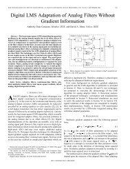
Fig. 15. Receiver single-ended S-parameters. The IRF control has been set at<br />
1.5 2.5, and 3.5 V to demonstrate tunability. The LO inputs to the mixer have<br />
0.4-V dc differential bias.<br />
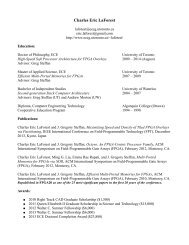
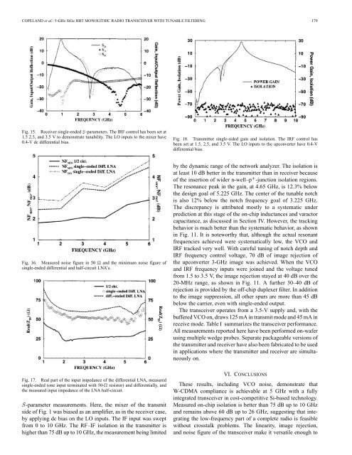
Fig. 18. Transmitter single-sided gain and isolation. The IRF control has<br />
been set at 1.5, 2.5, and 3.5 V. The LO inputs to the upconverter have 0.4-V<br />
differential bias.<br />
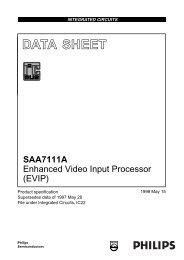
Fig. 16. Measured noise figure in 50 and the minimum noise figure of<br />
single-ended differential and half-circuit LNA’s.<br />
by the dynamic range of the network analyzer. The isolation is<br />
at least 10 dB better in the transmitter than in receiver because<br />
of the insertion of wider n-well–p -junction isolation regions.<br />
The resonance peak in the gain, at 4.65 <strong>GHz</strong>, is 12.3% below<br />
the design goal of 5.225 <strong>GHz</strong>. The center of the <strong>tunable</strong> notch<br />
is also 12% below the notch frequency goal of 3.225 <strong>GHz</strong>.<br />
The discrepancy is attributed mostly to a systematic under<br />
prediction at this stage of the on-chip inductances and varactor<br />
capacitance, as discussed in Section IV. However, the tracking<br />
behavior is much better than the systematic behavior, as shown<br />
in Fig. 11. It is noteworthy that, although the actual resonant<br />
frequencies achieved were systematically low, the VCO and<br />
IRF tracked very well. With careful tuning of notch depth and<br />
IRF frequency control voltage, 70 dB of image rejection of<br />
the upconverter 3-<strong>GHz</strong> image was achieved. When the VCO<br />
and IRF frequency inputs were joined and the voltage tuned<br />
from 1.5 to 3.5 V, the image rejection stayed at 40 dB over the<br />
20-MHz range, as shown in Fig. 11. A further 30–40 dB of<br />
rejection is provided by the off-chip duplexer filter. In addition<br />
to the image suppression, all other spurs are more than 45 dB<br />
below the carrier, even <strong>with</strong> single-ended output.<br />
The <strong>transceiver</strong> operates from a 3.5-V supply and, <strong>with</strong> the<br />
buffered VCO on, draws 125 mA in transmit mode and 45 mA in<br />
receive mode. Table I summarizes the <strong>transceiver</strong> performance.<br />
All measurements reported here have been performed on-wafer<br />
using multiple wedge probes. Separate packageable versions of<br />
the transmitter and receiver have also been fabricated to be used<br />
in applications where the transmitter and receiver are simultaneously<br />
on.<br />
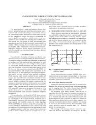
Fig. 17. Real part of the input impedance of the differential LNA, measured<br />
single-ended (one input terminated <strong>with</strong> 50- resistor) and differentially, and<br />
the measured input impedance of the LNA half-circuit.<br />
-parameter measurements. Here, the mixer of the transmit<br />
side of Fig. 1 was biased as an amplifier, as in the receiver case,<br />
by applying dc bias on the LO inputs. The IF input was swept<br />
from 0 to 10 <strong>GHz</strong>. The RF–IF isolation in the transmitter is<br />
higher than 75 dB up to 10 <strong>GHz</strong>, the measurement being limited<br />
VI. CONCLUSIONS<br />
These results, including VCO noise, demonstrate that<br />
W-CDMA compliance is achievable at 5 <strong>GHz</strong> <strong>with</strong> a fully<br />
integrated <strong>transceiver</strong> in cost-competitive Si-based technology.<br />
Measured on-chip isolation is better than 75 dB up to 10 <strong>GHz</strong><br />
and remains above 60 dB up to 26 <strong>GHz</strong>, suggesting that integrating<br />
the low-frequency part of a complete <strong>radio</strong> is feasible<br />
<strong>with</strong>out crosstalk problems. The linearity, image rejection,<br />
and noise figure of the <strong>transceiver</strong> make it versatile enough to