
Create successful ePaper yourself
Turn your PDF publications into a flip-book with our unique Google optimized e-Paper software.
10 CHAPTER 1 <strong>BASIC</strong> <strong>CONCEPTS</strong><br />
[hint]<br />
SOLUTION<br />
Elements that are<br />
connected in series have<br />
the same current.<br />
The current flow is out of the positive terminal of the 24-V source, and therefore this<br />
element is supplying (2)(24)=48 W of power. The current is into the positive terminals<br />
of elements 1 and 2, and therefore elements 1 and 2 are absorbing (2)(6)=12 W and<br />
(2)(18)=36 W, respectively. Note that the power supplied is equal to the power<br />
absorbed.<br />
Learning Assessment<br />
E1.3 Find the power that is absorbed or supplied by the elements in Fig. E1.3.<br />
18 V<br />
I=3 A+<br />
–<br />
1<br />
I=3 A<br />
+<br />
–<br />
12 V 3 A<br />
2 6 V<br />
–<br />
+<br />
Figure E1.3<br />
ANSWER: Current source<br />
supplies 36 W, element<br />
1 absorbs 54 W, and<br />
element 2 supplies 18 W.<br />
DEPENDENT SOURCES In contrast to the independent sources, which produce a<br />
particular voltage or current completely unaffected by what is happening in the remainder of<br />
the circuit, dependent sources generate a voltage or current that is determined by a voltage or<br />
current at a specified location in the circuit. These sources are very important because they<br />
are an integral part of the mathematical models used to describe the behavior of many electronic<br />
circuit elements.<br />
For example, metal-oxide-semiconductor field-effect transistors (MOSFETs) and bipolar<br />
transistors, both of which are commonly found in a host of electronic equipment, are modeled<br />
with dependent sources, and therefore the analysis of electronic circuits involves the use<br />
of these controlled elements.<br />
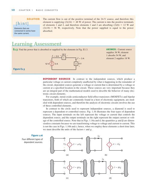
In contrast to the circle used to represent independent sources, a diamond is used to<br />
represent a dependent or controlled source. Fig. 1.16 illustrates the four types of dependent<br />
sources. The input terminals on the left represent the voltage or current that controls the<br />
dependent source, and the output terminals on the right represent the output current or voltage<br />
of the controlled source. Note that in Figs. 1.16a and d, the quantities and are dimensionless<br />
constants because we are transforming voltage to voltage and current to current. This<br />
is not the case in Figs. 1.16b and c; hence, when we employ these elements a short time later,<br />
we must describe the units of the factors r and g.<br />
Figure 1.16<br />
Four different types of<br />
dependent sources.<br />
+<br />
v S + –<br />
v=v S<br />
+ –<br />
v S i=gv S i=i S<br />
–<br />
(a)<br />
(b)<br />
i S<br />
+<br />
–<br />
i S<br />
(c)<br />
(d)