
You also want an ePaper? Increase the reach of your titles
YUMPU automatically turns print PDFs into web optimized ePapers that Google loves.
CHAPTER<br />
1<br />
<strong>BASIC</strong> <strong>CONCEPTS</strong><br />
THE LEARNING GOALS<br />
FOR THIS CHAPTER ARE:<br />
■ Review the SI system of units and standard prefixes<br />
■ Know the definitions of basic electrical<br />
quantities: voltage, current, and power<br />
■ Know the symbols for and definitions of<br />
independent and dependent sources<br />
■ Be able to calculate the power absorbed by a circuit<br />
element using the passive sign convention<br />
Courtesy NASA, 2009<br />
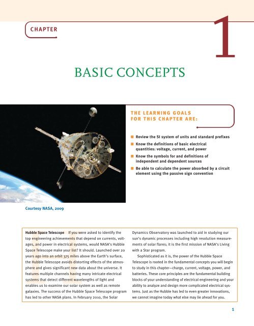
Hubble Space Telescope If you were asked to identify the<br />
top engineering achievements that depend on currents, voltages,<br />
and power in electrical systems, would NASA’s Hubble<br />
Space Telescope make your list? It should. Launched over 20<br />
years ago into an orbit 375 miles above the Earth’s surface,<br />
the Hubble Telescope avoids distorting effects of the atmosphere<br />
and gives significant new data about the universe. It<br />
features multiple channels having many intricate electrical<br />
systems that detect different wavelengths of light and<br />
enables us to examine our solar system as well as remote<br />
galaxies. The success of the Hubble Space Telescope program<br />
has led to other NASA plans. In February 2010, the Solar<br />
Dynamics Observatory was launched to aid in studying our<br />
sun’s dynamic processes including high resolution measurements<br />
of solar flares; it is the first mission of NASA’s Living<br />
with a Star program.<br />
Sophisticated as it is, the power of the Hubble Space<br />
Telescope is rooted in the fundamental concepts you will begin<br />
to study in this chapter—charge, current, voltage, power, and<br />
batteries. These core principles are the fundamental building<br />
blocks of your understanding of electrical engineering and your<br />
ability to analyze and design more complicated electrical systems.<br />
Just as the Hubble has led to even greater innovations,<br />
we cannot imagine today what else may lie ahead for you.<br />
1
2 CHAPTER 1 <strong>BASIC</strong> <strong>CONCEPTS</strong><br />
1.1<br />
System of Units<br />
The system of units we employ is the international system of units, the Système International<br />
des Unités, which is normally referred to as the SI standard system. This system, which is<br />
composed of the basic units meter (m), kilogram (kg), second (s), ampere (A), kelvin (K),<br />
and candela (cd), is defined in all modern physics texts and therefore will not be defined here.<br />
However, we will discuss the units in some detail as we encounter them in our subsequent<br />
analyses.<br />
The standard prefixes that are employed in SI are shown in Fig. 1.1. Note the decimal relationship<br />
between these prefixes. These standard prefixes are employed throughout our study<br />
of electric circuits.<br />
Circuit technology has changed drastically over the years. For example, in the early 1960s<br />
the space on a circuit board occupied by the base of a single vacuum tube was about the size<br />
of a quarter (25-cent coin). Today that same space could be occupied by an Intel Pentium<br />
integrated circuit chip containing 50 million transistors. These chips are the engine for a host<br />
of electronic equipment.<br />
Figure 1.1 ><br />
Standard SI prefixes.<br />
10 –12<br />
10 –9 10 –6 10 –3 1 10 3 10 6 10 9 10 12<br />
pico (p) nano (n) micro () milli (m)<br />
kilo (k) mega (M) giga (G) tera (T)<br />
1.2<br />
Basic Quantities<br />
I 1 =2 A<br />
Circuit 1<br />
(a)<br />
I 2 =–3 A<br />
Circuit 2<br />
(b)<br />
Figure 1.2<br />
Conventional current flow:<br />
(a) positive current flow;<br />
(b) negative current flow.<br />
Before we begin our analysis of electric circuits, we must define terms that we will employ.<br />
However, in this chapter and throughout the book our definitions and explanations will be as<br />
simple as possible to foster an understanding of the use of the material. No attempt will be<br />
made to give complete definitions of many of the quantities because such definitions are not<br />
only unnecessary at this level but are often confusing. Although most of us have an intuitive<br />
concept of what is meant by a circuit, we will simply refer to an electric circuit as an interconnection<br />
of electrical components, each of which we will describe with a mathematical<br />
model.<br />
The most elementary quantity in an analysis of electric circuits is the electric charge. Our<br />
interest in electric charge is centered around its motion, since charge in motion results in an<br />
energy transfer. Of particular interest to us are those situations in which the motion is confined<br />
to a definite closed path.<br />
An electric circuit is essentially a pipeline that facilitates the transfer of charge from<br />
one point to another. The time rate of change of charge constitutes an electric current.<br />
Mathematically, the relationship is expressed as<br />
i(t) = dq(t)<br />
t<br />
or q(t) = i(x) dx<br />
dt 3<br />
where i and q represent current and charge, respectively (lowercase letters represent time<br />
dependency, and capital letters are reserved for constant quantities). The basic unit of current<br />
is the ampere (A), and 1 ampere is 1 coulomb per second.<br />
Although we know that current flow in metallic conductors results from electron motion,<br />
the conventional current flow, which is universally adopted, represents the movement of positive<br />
charges. It is important that the reader think of current flow as the movement of positive<br />
charge regardless of the physical phenomena that take place. The symbolism that will be used<br />
to represent current flow is shown in Fig. 1.2. I 1 = 2 A in Fig. 1.2a indicates that at any point<br />
in the wire shown, 2 C of charge pass from left to right each second. I 2 =-3 A in Fig. 1.2b<br />
indicates that at any point in the wire shown, 3 C of charge pass from right to left each second.<br />
Therefore, it is important to specify not only the magnitude of the variable representing the<br />
current but also its direction.<br />
-q<br />
1.1
SECTION 1.2 <strong>BASIC</strong> QUANTITIES 3<br />
i(t)<br />
i(t)<br />
Figure 1.3<br />
Two common types<br />
of current: (a) alternating<br />
current (ac); (b) direct<br />
current (dc).<br />
t<br />
t<br />
(a)<br />
(b)<br />
The two types of current that we encounter often in our daily lives, alternating current (ac)<br />
and direct current (dc), are shown as a function of time in Fig. 1.3. Alternating current is the<br />
common current found in every household and is used to run the refrigerator, stove, washing<br />
machine, and so on. Batteries, which are used in automobiles and flashlights, are one source<br />
of direct current. In addition to these two types of currents, which have a wide variety of uses,<br />
we can generate many other types of currents. We will examine some of these other types<br />
later in the book. In the meantime, it is interesting to note that the magnitude of currents in<br />
elements familiar to us ranges from soup to nuts, as shown in Fig. 1.4.<br />
We have indicated that charges in motion yield an energy transfer. Now we define the<br />
voltage (also called the electromotive force, or potential) between two points in a circuit as the<br />
difference in energy level of a unit charge located at each of the two points. Voltage is very similar<br />
to a gravitational force. Think about a bowling ball being dropped from a ladder into a tank<br />
of water. As soon as the ball is released, the force of gravity pulls it toward the bottom of the<br />
tank. The potential energy of the bowling ball decreases as it approaches the bottom. The gravitational<br />
force is pushing the bowling ball through the water. Think of the bowling ball as a<br />
charge and the voltage as the force pushing the charge through a circuit. Charges in motion<br />
represent a current, so the motion of the bowling ball could be thought of as a current. The<br />
water in the tank will resist the motion of the bowling ball. The motion of charges in an electric<br />
circuit will be impeded or resisted as well. We will introduce the concept of resistance in<br />
Chapter 2 to describe this effect.<br />
Work or energy, w(t) or W, is measured in joules (J); 1 joule is 1 newton meter (N m).<br />
Hence, voltage [v(t) or V] is measured in volts (V) and 1 volt is 1 joule per coulomb; that is,<br />
1 volt=1 joule per coulomb=1 newton meter per coulomb. If a unit positive charge is<br />
moved between two points, the energy required to move it is the difference in energy level<br />
between the two points and is the defined voltage. It is extremely important that the variables<br />
used to represent voltage between two points be defined in such a way that the solution will<br />
let us interpret which point is at the higher potential with respect to the other.<br />
Current in amperes (A)<br />
10 6<br />
10 4<br />
10 2<br />
10 0<br />
10 –2<br />
10 –4<br />
10 –6<br />
10 –8<br />
Lightning bolt<br />
Large industrial motor current<br />
Typical household appliance current<br />
Causes ventricular fibrillation in humans<br />
Human threshold of sensation<br />
Integrated circuit (IC) memory cell current<br />
Figure 1.4<br />
Typical current magnitudes.<br />
10 –10<br />
10 –12<br />
10 –14<br />
Synaptic current (brain cell)
4 CHAPTER 1 <strong>BASIC</strong> <strong>CONCEPTS</strong><br />
Figure 1.5<br />
Voltage representations.<br />
A<br />
+<br />
–<br />
B<br />
A<br />
+<br />
–<br />
B<br />
A<br />
–<br />
C<br />
C<br />
i<br />
i<br />
V 1 =2 V<br />
r<br />
r<br />
c 1 V 2 =–5 V c 2 V 2 =5 V<br />
u<br />
i<br />
t<br />
u<br />
i<br />
t<br />
+<br />
B<br />
(a) (b) (c)<br />
C<br />
i<br />
r<br />
c 3<br />
u<br />
i<br />
t<br />
In Fig. 1.5a the variable that represents the voltage between points A and B has been<br />
defined as V 1 , and it is assumed that point A is at a higher potential than point B, as indicated<br />
by the ± and – signs associated with the variable and defined in the figure. The ± and – signs<br />
define a reference direction for V 1 . If V 1 = 2 V, then the difference in potential of points A<br />
and B is 2 V and point A is at the higher potential. If a unit positive charge is moved from<br />
point A through the circuit to point B, it will give up energy to the circuit and have 2 J less<br />
energy when it reaches point B. If a unit positive charge is moved from point B to point A,<br />
extra energy must be added to the charge by the circuit, and hence the charge will end up with<br />
2 J more energy at point A than it started with at point B.<br />
For the circuit in Fig. 1.5b, V 2 =-5 V means that the potential between points A and B is<br />
5 V and point B is at the higher potential. The voltage in Fig. 1.5b can be expressed as shown<br />
in Fig. 1.5c. In this equivalent case, the difference in potential between points A and B is<br />
V 2 = 5 V, and point B is at the higher potential.<br />
Note that it is important to define a variable with a reference direction so that the answer<br />
can be interpreted to give the physical condition in the circuit. We will find that it is not<br />
possible in many cases to define the variable so that the answer is positive, and we will also<br />
find that it is not necessary to do so.<br />
As demonstrated in Figs. 1.5b and c, a negative number for a given variable, for example,<br />
V 2 in Fig. 1.5b, gives exactly the same information as a positive number, that is, V 2 in Fig. 1.5c,<br />
except that it has an opposite reference direction. Hence, when we define either current or voltage,<br />
it is absolutely necessary that we specify both magnitude and direction. Therefore, it is<br />
incomplete to say that the voltage between two points is 10 V or the current in a line is 2 A,<br />
since only the magnitude and not the direction for the variables has been defined.<br />
The range of magnitudes for voltage, equivalent to that for currents in Fig. 1.4, is shown<br />
in Fig. 1.6. Once again, note that this range spans many orders of magnitude.<br />
Figure 1.6<br />
Typical voltage magnitudes.<br />
Voltage in volts (V)<br />
10 8<br />
10 6<br />
10 4<br />
10 2<br />
10 0<br />
10–2<br />
10–4<br />
10–6<br />
10–8<br />
Lightning bolt<br />
High-voltage transmission lines<br />
Voltage on a TV picture tube<br />
Large industrial motors<br />
ac outlet plug in U.S. households<br />
Car battery<br />
Voltage on integrated circuits<br />
Flashlight battery<br />
Voltage across human chest produced by the<br />
heart (EKG)<br />
Voltage between two points on human scalp (EEG)<br />
Antenna of a radio receiver<br />
10–10
SECTION 1.2 <strong>BASIC</strong> QUANTITIES 5<br />
Figure 1.7<br />
Flashlight circuit.<br />
Switch<br />
–<br />
Battery<br />
+<br />
Light bulb<br />
At this point we have presented the conventions that we employ in our discussions of<br />
current and voltage. Energy is yet another important term of basic significance. Let’s<br />
investigate the voltage–current relationships for energy transfer using the flashlight shown in<br />
Fig. 1.7. The basic elements of a flashlight are a battery, a switch, a light bulb, and connecting<br />
wires. Assuming a good battery, we all know that the light bulb will glow when the switch<br />
is closed. A current now flows in this closed circuit as charges flow out of the positive terminal<br />
of the battery through the switch and light bulb and back into the negative terminal of<br />
the battery. The current heats up the filament in the bulb, causing it to glow and emit light.<br />
The light bulb converts electrical energy to thermal energy; as a result, charges passing<br />
through the bulb lose energy. These charges acquire energy as they pass through the battery<br />
as chemical energy is converted to electrical energy. An energy conversion process is occurring<br />
in the flashlight as the chemical energy in the battery is converted to electrical energy,<br />
which is then converted to thermal energy in the light bulb.<br />
Figure 1.8<br />
Flashlight circuit with<br />
voltages and current.<br />
–<br />
Battery +<br />
I<br />
– V battery +<br />
+V bulb –<br />
Let’s redraw the flashlight as shown in Fig. 1.8. There is a current I flowing in this diagram.<br />
Since we know that the light bulb uses energy, the charges coming out of the bulb have<br />
less energy than those entering the light bulb. In other words, the charges expend energy as<br />
they move through the bulb. This is indicated by the voltage shown across the bulb. The<br />
charges gain energy as they pass through the battery, which is indicated by the voltage across<br />
the battery. Note the voltage–current relationships for the battery and bulb. We know that the<br />
bulb is absorbing energy; the current is entering the positive terminal of the voltage. For the<br />
battery, the current is leaving the positive terminal, which indicates that energy is being<br />
supplied.<br />
This is further illustrated in Fig. 1.9, where a circuit element has been extracted from a<br />
larger circuit for examination. In Fig. 1.9a, energy is being supplied to the element by<br />
whatever is attached to the terminals. Note that 2 A, that is, 2 C of charge are moving from<br />
point A to point B through the element each second. Each coulomb loses 3 J of energy as it<br />
passes through the element from point A to point B. Therefore, the element is absorbing 6 J<br />
of energy per second. Note that when the element is absorbing energy, a positive current<br />
enters the positive terminal. In Fig. 1.9b energy is being supplied by the element to whatever<br />
is connected to terminals A-B. In this case, note that when the element is supplying energy,<br />
a positive current enters the negative terminal and leaves via the positive terminal. In this convention,<br />
a negative current in one direction is equivalent to a positive current in the opposite<br />
direction, and vice versa. Similarly, a negative voltage in one direction is equivalent to a positive<br />
voltage in the opposite direction.<br />
A<br />
+<br />
3 V<br />
–<br />
B<br />
A<br />
+<br />
3 V<br />
–<br />
B<br />
I=2 A<br />
I=2 A<br />
(a)<br />
(b)<br />
I=2 A<br />
I=2 A<br />
Figure 1.9<br />
Voltage–current relationships<br />
for (a) energy absorbed and<br />
(b) energy supplied.
6 CHAPTER 1 <strong>BASIC</strong> <strong>CONCEPTS</strong><br />
EXAMPLE<br />
1.1<br />
Suppose that your car will not start. To determine whether the battery is faulty, you turn on<br />
the light switch and find that the lights are very dim, indicating a weak battery. You borrow<br />
a friend’s car and a set of jumper cables. However, how do you connect his car’s battery to<br />
yours? What do you want his battery to do?<br />
SOLUTION<br />
Figure 1.10<br />
Diagram for Example 1.1.<br />
Essentially, his car’s battery must supply energy to yours, and therefore it should be<br />
connected in the manner shown in Fig. 1.10. Note that the positive current leaves the positive<br />
terminal of the good battery (supplying energy) and enters the positive terminal of the<br />
weak battery (absorbing energy). Note that the same connections are used when charging a<br />
battery.<br />
I<br />
I<br />
+ – + –<br />
Good<br />
battery<br />
Weak<br />
battery<br />
In practical applications there are often considerations other than simply the electrical<br />
relations (e.g., safety). Such is the case with jump-starting an automobile. Automobile<br />
batteries produce explosive gases that can be ignited accidentally, causing severe physical<br />
injury. Be safe—follow the procedure described in your auto owner’s manual.<br />
We have defined voltage in joules per coulomb as the energy required to move a positive<br />
charge of 1 C through an element. If we assume that we are dealing with a differential amount<br />
of charge and energy, then<br />
v = dw<br />
dq<br />
1.2<br />
Multiplying this quantity by the current in the element yields<br />
vi = dw<br />
dq a dq<br />
dt b = dw dt<br />
= p<br />
1.3<br />
i(t)<br />
+<br />
v(t)<br />
Figure 1.11<br />
Sign convention for power.<br />
[hint]<br />
–<br />
The passive sign convention<br />
is used to determine whether<br />
power is being absorbed or<br />
supplied.<br />
which is the time rate of change of energy or power measured in joules per second, or watts<br />
(W). Since, in general, both v and i are functions of time, p is also a time-varying quantity.<br />
Therefore, the change in energy from time t 1 to time t 2 can be found by integrating Eq. (1.3);<br />
that is,<br />
t 2<br />
t 2<br />
¢w = p dt = vi dt<br />
3 t 1 3<br />
At this point, let us summarize our sign convention for power. To determine the sign of<br />
any of the quantities involved, the variables for the current and voltage should be arranged as<br />
shown in Fig. 1.11. The variable for the voltage v(t) is defined as the voltage across the element<br />
with the positive reference at the same terminal that the current variable i(t) is entering.<br />
This convention is called the passive sign convention and will be so noted in the remainder<br />
of this book. The product of v and i, with their attendant signs, will determine the magnitude<br />
and sign of the power. If the sign of the power is positive, power is being absorbed by the element;<br />
if the sign is negative, power is being supplied by the element.<br />
t 1<br />
1.4
SECTION 1.2 <strong>BASIC</strong> QUANTITIES 7<br />
Given the two diagrams shown in Fig. 1.12, determine whether the element is absorbing or<br />
supplying power and how much.<br />
–<br />
2 V<br />
+<br />
4 A<br />
(a)<br />
–<br />
2 V<br />
+<br />
+<br />
2 V<br />
–<br />
–2 A<br />
(b)<br />
+<br />
2 V<br />
–<br />
Figure 1.12<br />
EXAMPLE<br />
1.2<br />
Elements for Example 1.2.<br />
In Fig. 1.12a the power is P=(2 V)(–4 A)=–8 W. Therefore, the element is supplying<br />
power. In Fig. 1.12b, the power is P=(2 V)(–2 A)=–4 W. Therefore, the element is<br />
supplying power.<br />
SOLUTION<br />
Learning Assessment<br />
E1.1 Determine the amount of power absorbed or supplied by the elements in Fig. E1.1.<br />
ANSWER:<br />
(a) P =-48 W;<br />
(b) P = 8 W.<br />
+<br />
V 1 =12 V<br />
–<br />
+<br />
12 V<br />
–<br />
I=4 A<br />
+<br />
V 1 =4 V<br />
–<br />
I=2 A<br />
+<br />
4 V<br />
–<br />
Figure E1.1<br />
(a)<br />
(b)<br />
We wish to determine the unknown voltage or current in Fig. 1.13.<br />
5 A<br />
I=?<br />
A<br />
–A<br />
V 1 =? P=–20 W<br />
5 V P=40 W<br />
B<br />
±B<br />
(a)<br />
(b)<br />
–<br />
5 V<br />
+<br />
EXAMPLE<br />
1.3<br />
Figure 1.13<br />
Elements for Example 1.3.<br />
In Fig. 1.13a, a power of –20 W indicates that the element is delivering power. Therefore,<br />
the current enters the negative terminal (terminal A), and from Eq. (1.3) the voltage is 4 V.<br />
Thus, B is the positive terminal, A is the negative terminal, and the voltage between them is<br />
4V.<br />
In Fig 1.13b, a power of ±40 W indicates that the element is absorbing power and, therefore,<br />
the current should enter the positive terminal B. The current thus has a value of –8 A,<br />
as shown in the figure.<br />
SOLUTION
8 CHAPTER 1 <strong>BASIC</strong> <strong>CONCEPTS</strong><br />
Learning Assessment<br />
E1.2 Determine the unknown variables in Fig. E1.2.<br />
I=2 A<br />
ANSWER:<br />
(a) V 1 =-20 V;<br />
(b) I =-5 A.<br />
– P=40 W<br />
V 1 =?<br />
+<br />
+ P=–50 W<br />
V 1 =10 V<br />
–<br />
+<br />
10 V<br />
–<br />
I=?<br />
Figure E1.2<br />
(a)<br />
(b)<br />
Finally, it is important to note that our electrical networks satisfy the principle of conservation<br />
of energy. Because of the relationship between energy and power, it can be implied<br />
that power is also conserved in an electrical network. This result was formally stated in 1952<br />
by B. D. H. Tellegen and is known as Tellegen’s theorem—the sum of the powers absorbed<br />
by all elements in an electrical network is zero. Another statement of this theorem is that the<br />
power supplied in a network is exactly equal to the power absorbed. Checking to verify that<br />
Tellegen’s theorem is satisfied for a particular network is one way to check our calculations<br />
when analyzing electrical networks.<br />
1.3<br />
Circuit Elements<br />
Thus far we have defined voltage, current, and power. In the remainder of this chapter we will<br />
define both independent and dependent current and voltage sources. Although we will<br />
assume ideal elements, we will try to indicate the shortcomings of these assumptions as we<br />
proceed with the discussion.<br />
In general, the elements we will define are terminal devices that are completely characterized<br />
by the current through the element and/or the voltage across it. These elements, which<br />
we will employ in constructing electric circuits, will be broadly classified as being either<br />
active or passive. The distinction between these two classifications depends essentially on<br />
one thing—whether they supply or absorb energy. As the words themselves imply, an active<br />
element is capable of generating energy and a passive element cannot generate energy.<br />
However, later we will show that some passive elements are capable of storing energy.<br />
Typical active elements are batteries and generators. The three common passive elements are<br />
resistors, capacitors, and inductors.<br />
In Chapter 2 we will launch an examination of passive elements by discussing the resistor<br />
in detail. Before proceeding with that element, we first present some very important active<br />
elements.<br />
1. Independent voltage source 3. Two dependent voltage sources<br />
2. Independent current source 4. Two dependent current sources<br />
INDEPENDENT SOURCES An independent voltage source is a two-terminal element<br />
that maintains a specified voltage between its terminals regardless of the current through it<br />
as shown by the v-i plot in Fig. 1.14a. The general symbol for an independent source, a circle,<br />
is also shown in Fig. 1.14a. As the figure indicates, terminal A is v(t) volts positive with<br />
respect to terminal B.<br />
In contrast to the independent voltage source, the independent current source is a twoterminal<br />
element that maintains a specified current regardless of the voltage across its<br />
terminals, as illustrated by the v-i plot in Fig. 1.14b. The general symbol for an independent<br />
current source is also shown in Fig. 1.14b, where i(t) is the specified current and the arrow<br />
indicates the positive direction of current flow.
SECTION 1.3 CIRCUIT ELEMENTS 9<br />
v<br />
Figure 1.14<br />
v<br />
v(t) + –<br />
i(t)<br />
Symbols for (a) independent<br />
voltage source, (b) independent<br />
current source.<br />
i<br />
i<br />
A<br />
A<br />
B<br />
(a)<br />
B<br />
(b)<br />
In their normal mode of operation, independent sources supply power to the remainder of<br />
the circuit. However, they may also be connected into a circuit in such a way that they absorb<br />
power. A simple example of this latter case is a battery-charging circuit such as that shown<br />
in Example 1.1.<br />
It is important that we pause here to interject a comment concerning a shortcoming of the<br />
models. In general, mathematical models approximate actual physical systems only under a certain<br />
range of conditions. Rarely does a model accurately represent a physical system under<br />
every set of conditions. To illustrate this point, consider the model for the voltage source in<br />
Fig. 1.14a. We assume that the voltage source delivers v volts regardless of what is connected<br />
to its terminals. Theoretically, we could adjust the external circuit so that an infinite amount of<br />
current would flow, and therefore the voltage source would deliver an infinite amount of power.<br />
This is, of course, physically impossible. A similar argument could be made for the independent<br />
current source. Hence, the reader is cautioned to keep in mind that models have limitations<br />
and thus are valid representations of physical systems only under certain conditions.<br />
For example, can the independent voltage source be utilized to model the battery in an<br />
automobile under all operating conditions? With the headlights on, turn on the radio. Do the<br />
headlights dim with the radio on? They probably won’t if the sound system in your automobile<br />
was installed at the factory. If you try to crank your car with the headlights on, you will<br />
notice that the lights dim. The starter in your car draws considerable current, thus causing the<br />
voltage at the battery terminals to drop and dimming the headlights. The independent voltage<br />
source is a good model for the battery with the radio turned on; however, an improved<br />
model is needed for your battery to predict its performance under cranking conditions.<br />
Determine the power absorbed or supplied by the elements in the network in Fig. 1.15.<br />
6 V<br />
I=2 A+<br />
–<br />
1<br />
I=2 A<br />
EXAMPLE<br />
1.4<br />
+<br />
24 V + 2 18 V<br />
– –<br />
Figure 1.15<br />
I=2 A<br />
Network for Example 1.4.
10 CHAPTER 1 <strong>BASIC</strong> <strong>CONCEPTS</strong><br />
[hint]<br />
SOLUTION<br />
Elements that are<br />
connected in series have<br />
the same current.<br />
The current flow is out of the positive terminal of the 24-V source, and therefore this<br />
element is supplying (2)(24)=48 W of power. The current is into the positive terminals<br />
of elements 1 and 2, and therefore elements 1 and 2 are absorbing (2)(6)=12 W and<br />
(2)(18)=36 W, respectively. Note that the power supplied is equal to the power<br />
absorbed.<br />
Learning Assessment<br />
E1.3 Find the power that is absorbed or supplied by the elements in Fig. E1.3.<br />
18 V<br />
I=3 A+<br />
–<br />
1<br />
I=3 A<br />
+<br />
–<br />
12 V 3 A<br />
2 6 V<br />
–<br />
+<br />
Figure E1.3<br />
ANSWER: Current source<br />
supplies 36 W, element<br />
1 absorbs 54 W, and<br />
element 2 supplies 18 W.<br />
DEPENDENT SOURCES In contrast to the independent sources, which produce a<br />
particular voltage or current completely unaffected by what is happening in the remainder of<br />
the circuit, dependent sources generate a voltage or current that is determined by a voltage or<br />
current at a specified location in the circuit. These sources are very important because they<br />
are an integral part of the mathematical models used to describe the behavior of many electronic<br />
circuit elements.<br />
For example, metal-oxide-semiconductor field-effect transistors (MOSFETs) and bipolar<br />
transistors, both of which are commonly found in a host of electronic equipment, are modeled<br />
with dependent sources, and therefore the analysis of electronic circuits involves the use<br />
of these controlled elements.<br />
In contrast to the circle used to represent independent sources, a diamond is used to<br />
represent a dependent or controlled source. Fig. 1.16 illustrates the four types of dependent<br />
sources. The input terminals on the left represent the voltage or current that controls the<br />
dependent source, and the output terminals on the right represent the output current or voltage<br />
of the controlled source. Note that in Figs. 1.16a and d, the quantities and are dimensionless<br />
constants because we are transforming voltage to voltage and current to current. This<br />
is not the case in Figs. 1.16b and c; hence, when we employ these elements a short time later,<br />
we must describe the units of the factors r and g.<br />
Figure 1.16<br />
Four different types of<br />
dependent sources.<br />
+<br />
v S + –<br />
v=v S<br />
+ –<br />
v S i=gv S i=i S<br />
–<br />
(a)<br />
(b)<br />
i S<br />
+<br />
–<br />
i S<br />
(c)<br />
(d)
SECTION 1.3 CIRCUIT ELEMENTS 11<br />
Given the two networks shown in Fig. 1.17, we wish to determine the outputs.<br />
In Fig. 1.17a the output voltage is V o = V S or V o = 20 V S =(20)(2 V)=40 V. Note that<br />
the output voltage has been amplified from 2 V at the input terminals to 40 V at the output<br />
terminals; that is, the circuit is a voltage amplifier with an amplification factor of 20.<br />
SOLUTION<br />
EXAMPLE<br />
1.5<br />
I S =1 mA<br />
I o<br />
+<br />
+<br />
V S =2 V<br />
+ –<br />
Figure 1.17<br />
20V S =V o<br />
V o<br />
50I S =I o<br />
–<br />
–<br />
(a)<br />
In Fig. 1.17b, the output current is I o = I S = (50)(1 mA) = 50 mA; that is, the circuit has<br />
a current gain of 50, meaning that the output current is 50 times greater than the input current.<br />
Learning Assessment<br />
E1.4 Determine the power supplied by the dependent sources in Fig. E1.4.<br />
+<br />
V S =4 V<br />
–<br />
±<br />
–<br />
I o =2 A<br />
10V S<br />
I S =4 A<br />
(b)<br />
+<br />
1 10 V 4 I S 1<br />
–<br />
Circuits for Example 1.5.<br />
ANSWER:<br />
(a) Power supplied = 80 W;<br />
(b) power supplied = 160 W.<br />
Figure E1.4<br />
(a)<br />
(b)<br />
Calculate the power absorbed by each element in the network of Fig. 1.18. Also verify that<br />
Tellegen’s theorem is satisfied by this network.<br />
24 V<br />
3 A<br />
1 A<br />
8 V<br />
+ -<br />
4<br />
2 A<br />
12 V<br />
+ -<br />
3<br />
+<br />
±<br />
– 16 V 1 12 V<br />
-<br />
4 V<br />
+ -<br />
2<br />
1 A<br />
±<br />
–<br />
1 A 2 A<br />
Let’s calculate the power absorbed by each element using the sign convention for power.<br />
P 1 = (16)(1) = 16 W<br />
P 2 = (4)(1) = 4 W<br />
P 3 = (12)(1) = 12 W<br />
SOLUTION<br />
EXAMPLE<br />
1.6<br />
Figure 1.18<br />
Circuit used in Example 1.6.
12 CHAPTER 1 <strong>BASIC</strong> <strong>CONCEPTS</strong><br />
P 4 = (8)(2) = 16 W<br />
P 12V = (12)(2) = 24 W<br />
P 24V = (24)(-3) =-72 W<br />
Note that to calculate the power absorbed by the 24-V source, the current of 3 A flowing up<br />
through the source was changed to a current 3 A flowing down through the 24-V source.<br />
Let’s sum up the power absorbed by all elements: 16 4 12 16 24 72 0<br />
This sum is zero, which verifies that Tellegen’s theorem is satisfied.<br />
EXAMPLE<br />
1.7<br />
Use Tellegen’s theorem to find the current I o in the network in Fig. 1.19.<br />
6 V<br />
– +<br />
I x =2 A<br />
2 A<br />
Figure 1.19<br />
Circuit used in Example 1.7.<br />
SOLUTION<br />
3 A<br />
6 V<br />
12 V<br />
+ – – +<br />
1 2<br />
I o<br />
9 A<br />
+<br />
3 10 V ± 4 V ±<br />
–<br />
–<br />
–<br />
8 A<br />
First, we must determine the power absorbed by each element in the network. Using the sign<br />
convention for power, we find<br />
Applying Tellegen’s theorem yields<br />
or<br />
Hence,<br />
P 2 A = (6)(-2) =-12 W<br />
P 1 = (6)AI o B = 6I o W<br />
P 2 = (12)(-9) =-108 W<br />
P 3 = (10)(-3) =-30 W<br />
P 4 V = (4)(-8) =-32 W<br />
6I o + 176 = 12 + 108 + 30 + 32<br />
I o = 1A<br />
11 A<br />
P DS = A8I x B(11) = (16)(11) = 176 W<br />
-12 + 6I o - 108 - 30 - 32 + 176 = 0<br />
8I x<br />
Learning Assessment<br />
E1.5 Find the power that is absorbed or supplied by the circuit elements in the network in<br />
Fig. E1.5.<br />
8 V<br />
+ –<br />
1<br />
ANSWER:<br />
P 24 V = 96 W supplied;<br />
P 1 = 32 W absorbed;<br />
P 4Ix = 64 W absorbed.<br />
Figure E1.5<br />
24 V<br />
±<br />
–<br />
I x =4 A<br />
±<br />
–<br />
4I x
SECTION 1.3 CIRCUIT ELEMENTS 13<br />
E1.6 Find the power that is absorbed<br />
or supplied by the network elements in<br />
Fig. E1.6.<br />
Figure E1.6<br />
2I x<br />
–+<br />
1<br />
+<br />
6 V<br />
–<br />
24 V + + –<br />
–<br />
12 V<br />
9 V<br />
– +<br />
2<br />
I x =1.5 A<br />
ANSWER:<br />
P 24V = 36 W supplied,<br />
P 12V = 18 W absorbed,<br />
P 21x = 4.5 W supplied,<br />
P 1 = 9 W absorbed,<br />
P 2 = 13.5 W absorbed.<br />
E1.7 Find I x in Fig. E1.7 using<br />
Tellegen’s theorem.<br />
1 A<br />
+<br />
+<br />
10 V<br />
–<br />
2 A<br />
+<br />
I x 3 15 V<br />
–<br />
ANSWER:<br />
I x =-2 A.<br />
1<br />
25 V<br />
–<br />
5 A<br />
+<br />
2 15 V + –<br />
–<br />
10 V<br />
Figure E1.7<br />
The charge that enters the BOX is shown in Fig. 1.20. Calculate and sketch the current flowing<br />
into and the power absorbed by the BOX between 0 and 10 milliseconds.<br />
i (t)<br />
EXAMPLE<br />
1.8<br />
12 V ±<br />
BOX<br />
–<br />
q(t) (mC)<br />
3<br />
2<br />
1<br />
5 6<br />
1 2 3 4<br />
7 8 9 10<br />
t (ms)<br />
–1<br />
–2<br />
–3<br />
Figure 1.20<br />
Diagrams for Example 1.8.
14 CHAPTER 1 <strong>BASIC</strong> <strong>CONCEPTS</strong><br />
SOLUTION Recall that current is related to charge by i(t) = dq(t) . The current is equal to the slope of<br />
dt<br />
the charge waveform.<br />
i(t) = 0<br />
0 t 1 ms<br />
i(t) = 3 * 10-3 - 1 * 10 -3<br />
1 t 2 ms<br />
2 * 10 -3 - 1 * 10 = 2A -3<br />
i(t) = 0<br />
i(t) = -2 * 10-3 - 3 * 10 -3<br />
5 * 10 -3 - 3 * 10 -3 =-2.5 A<br />
i(t) = 0<br />
i(t) = 2 * 10-3 - (-2 * 10 -3 )<br />
9 * 10 -3 - 6 * 10 -3 = 1.33 A<br />
2 t 3 ms<br />
3 t 5 ms<br />
5 t 6 ms<br />
6 t 9 ms<br />
i(t) = 0<br />
t 9 ms<br />
The current is plotted with the charge waveform in Fig. 1.21. Note that the current is zero<br />
during times when the charge is a constant value. When the charge is increasing, the current<br />
is positive, and when the charge is decreasing, the current is negative.<br />
Figure 1.21<br />
Charge and current<br />
waveforms for Example 1.8.<br />
3<br />
2<br />
q(t) (mC), i(t) (A)<br />
1<br />
5 6<br />
1 2 3 4<br />
7 8 9 10<br />
t (ms)<br />
–1<br />
–2<br />
–3<br />
The power absorbed by the BOX is 12 i(t).<br />
p(t) = 12*0 = 0<br />
p(t) = 12*2 = 24 W<br />
p(t) = 12*0 = 0<br />
p(t) = 12*(-2.5) =-30 W<br />
p(t) = 12*0 = 0<br />
p(t) = 12*1.33 = 16 W<br />
p(t) = 12*0 = 0<br />
0 t 1 ms<br />
1 t 2 ms<br />
2 t 3 ms<br />
3 t 5 ms<br />
5 t 6 ms<br />
6 t 9 ms<br />
t 9 ms<br />
The power absorbed by the BOX is plotted in Fig. 1.22. For the time intervals, 1 t 2 ms<br />
and 6 t 9 ms, the BOX is absorbing power. During the time interval 3 t 5 ms, the<br />
power absorbed by the BOX is negative, which indicates that the BOX is supplying power<br />
to the 12-V source.
SECTION 1.3 CIRCUIT ELEMENTS 15<br />
36<br />
24<br />
p(t) (W)<br />
Figure 1.22<br />
Power waveform for<br />
Example 1.8.<br />
12<br />
5 6<br />
1 2 3 4<br />
7 8 9 10<br />
t (ms)<br />
–12<br />
–24<br />
–36<br />
Learning Assessment<br />
E1.8 The power absorbed by the BOX in Fig. El.8 is<br />
p(t) = 2.5e -4t W. Compute the energy and charge delivered<br />
to the BOX in the time interval 0 6 t 6 250 ms.<br />
50e –t V<br />
+ –<br />
i (t)<br />
BOX<br />
ANSWER: 395.1 mJ,<br />
8.8 mC.<br />
Figure E1.8<br />
E1.9 The energy absorbed by the BOX in Fig. El.9 is given below. Calculate and sketch the current<br />
flowing into the BOX. Also calculate the charge that enters the BOX between 0 and 12 seconds.<br />
i (t)<br />
10 V + BOX<br />
–<br />
w(t) (J)<br />
5<br />
7 8 9 10 11 12<br />
1 2 3 4 5 6<br />
t (s)<br />
–2.5<br />
Figure E1.9
16 CHAPTER 1 <strong>BASIC</strong> <strong>CONCEPTS</strong><br />
i(t) (A)<br />
ANSWER: Q = 0.<br />
0.25<br />
0.125<br />
4 5 6 7 8<br />
–0.125<br />
1 2 3<br />
9 10 11 12<br />
t (s)<br />
–0.25<br />
EXAMPLE<br />
1.9<br />
A Universal Serial Bus (USB) port is a common feature on both desktop and notebook<br />
computers as well as many handheld devices such as MP3 players, digital cameras, and cell<br />
phones. The USB 2.0 specification (www.usb.org) permits data transfer between a computer<br />
and a peripheral device at rates up to 480 megabits per second. One important feature of<br />
USB is the ability to swap peripherals without having to power down a computer. USB ports<br />
are also capable of supplying power to external peripherals. Fig. 1.23 shows a Motorola<br />
RAZR® and an Apple iPod® being charged from the USB ports on a notebook computer.<br />
A USB cable is a four-conductor cable with two signal conductors and two conductors for<br />
providing power. The amount of current that can be provided over a USB port is defined in<br />
the USB specification in terms of unit loads, where one unit load is specified to be 100 mA.<br />
All USB ports default to low-power ports at one unit load, but can be changed under software<br />
control to high-power ports capable of supplying up to five unit loads or 500 mA.<br />
Figure 1.23<br />
Charging a Motorola RAZR®<br />
and Apple iPod® from USB<br />
ports. (Courtesy of Mark<br />
Nelms and Jo Ann Loden)
PROBLEMS 17<br />
1. A 680 mAh lithium-ion battery is standard in a Motorola RAZR®. If this battery<br />
is completely discharged (i.e., 0 mAh), how long will it take to recharge the battery<br />
to its full capacity of 680 mAh from a low-power USB port? How much charge is<br />
stored in the battery at the end of the charging process?<br />
2. A third-generation iPod® with a 630 mAh lithium-ion battery is to be recharged<br />
from a high-power USB port supplying 150 mA of current. At the beginning of the<br />
recharge, 7.8 C of charge are stored in the battery. The recharging process halts when<br />
the stored charge reaches 35.9 C. How long does it take to recharge the battery?<br />
1. A low-power USB port operates at 100 mA. Assuming that the charging current<br />
from the USB port remains at 100 mA throughout the charging process, the time<br />
required to recharge the battery is 680 mAh100 mA = 6.8 h. The charge stored in<br />
the battery when fully charged is 680mAh 60 sh = 40,800 mAs = 40.8 As =<br />
40.8 C.<br />
2. The charge supplied to the battery during the recharging process is<br />
35.9 - 7.8 = 28.1 C. This corresponds to 28.1 As = 28,100 mAs 1h60s =<br />
468.3 mAh. Assuming a constant charging current of 150 mA from the high-power<br />
USB port, the time required to recharge the battery is 468.3 mAh150 mA = 3.12 h.<br />
SOLUTION<br />
SUMMARY<br />
•<br />
■<br />
■<br />
■<br />
The standard prefixes employed<br />
p = 10 -12<br />
k = 10 3<br />
n = 10 -9 M = 10 6<br />
= 10 -6<br />
G = 10 9<br />
m = 10 -3 T = 10 12<br />
The relationships between current and<br />
charge<br />
i(t) = dq(t)<br />
t<br />
or q(t) = i(x) dx<br />
dt 3<br />
The relationships among power, energy,<br />
current, and voltage<br />
p = dw dt<br />
= vi<br />
t 2<br />
t 2<br />
¢w = p dt = vi dt<br />
3 t 1 3<br />
t 1<br />
-q<br />
■ The passive sign convention The passive sign<br />
convention states that if the voltage and current associated<br />
with an element are as shown in Fig. 1.11, the product of<br />
v and i, with their attendant signs, determines the<br />
magnitude and sign of the power. If the sign is positive,<br />
power is being absorbed by the element, and if the sign is<br />
negative, the element is supplying power.<br />
■ Independent and dependent sources An<br />
ideal independent voltage (current) source is a two-terminal<br />
element that maintains a specified voltage (current) between<br />
its terminals, regardless of the current (voltage) through<br />
(across) the element. Dependent or controlled sources<br />
generate a voltage or current that is determined by a voltage<br />
or current at a specified location in the circuit.<br />
■ Conservation of energy The electric circuits<br />
under investigation satisfy the conservation of energy.<br />
■ Tellegen’s theorem The sum of the powers<br />
absorbed by all elements in an electrical network is zero.<br />
PROBLEMS<br />
•<br />
1.1 If the current in an electric conductor is 2.4 A, how<br />
many coulombs of charge pass any point in a 30-second<br />
interval?<br />
1.2 Determine the time interval required for a 12-A battery<br />
charger to deliver 4800 C.<br />
1.3 A lightning bolt carrying 30,000 A lasts for 50 microseconds.<br />
If the lightning strikes an airplane flying at<br />
20,000 feet, what is the charge deposited on the plane?<br />
1.4 If a 12-V battery delivers 100 J in 5 s, find (a) the amount<br />
of charge delivered and (b) the current produced.
18 CHAPTER 1 <strong>BASIC</strong> <strong>CONCEPTS</strong><br />
1.5 The current in a conductor is 1.5 A. How many coulombs of<br />
charge pass any point in a time interval of 1.5 minutes?<br />
1.6 If 60 C of charge pass through an electric conductor in<br />
30 seconds, determine the current in the conductor.<br />
1.7 Determine the number of coulombs of charge produced by<br />
a 12-A battery charger in an hour.<br />
1.8 Five coulombs of charge pass through the element in<br />
Fig. P1.8 from point A to point B. If the energy absorbed by<br />
the element is 120 J, determine the voltage across the<br />
element.<br />
-<br />
A<br />
Figure P1.8<br />
1.9 The current that enters an element is shown in<br />
Fig. P1.9. Find the charge that enters the element<br />
in the time interval 0 6 t 6 20 s.<br />
10<br />
i(t) mA<br />
B<br />
+<br />
V 1<br />
1.11 The charge entering the positive terminal of an element is<br />
given by the expression q(t) =-12e -2t mC. The power<br />
delivered to the element is p(t) = 2.4e -3t W. Compute<br />
the current in the element, the voltage across the element,<br />
and the energy delivered to the element in the time<br />
interval 0 6 t 6 100 ms.<br />
1.12 The voltage across an element is 12e -2t V. The current<br />
entering the positive terminal of the element is .<br />
Find the energy absorbed by the element in 1.5 s starting<br />
from t 0.<br />
1.13 The power absorbed by the BOX in Fig. P1.13 is<br />
2e -2t W. Calculate the amount of charge that enters the<br />
BOX between 0.1 and 0.4 seconds.<br />
4e –t V<br />
Figure P1.13<br />
+ –<br />
2e -2t A<br />
BOX<br />
1.14 The power absorbed by the BOX in Fig. P1.14 is<br />
0.1e -4t W. Calculate the energy absorbed by the BOX<br />
during this same time interval.<br />
0<br />
Figure P1.9<br />
10 20<br />
t (s)<br />
10e –2t V<br />
+ –<br />
BOX<br />
1.10 The charge entering the positive terminal of an element is<br />
q(t) =-30e -4t mC. If the voltage across the element is<br />
120e -2t V, determine the energy delivered to the element<br />
in the time interval 0 6 t 6 50 ms.<br />
Figure P1.14<br />
1.15 The energy absorbed by the BOX in Fig. P1.15 is shown below. How much charge enters<br />
the BOX between 0 and 10 milliseconds?<br />
w(t) (mJ)<br />
i (t)<br />
15 V + BOX<br />
–<br />
15<br />
10<br />
5<br />
1 2 3 4 5 6 7 8 9 10<br />
t (ms)<br />
–5<br />
–10<br />
Figure P1.15<br />
–15
PROBLEMS 19<br />
1.16 The charge that enters the BOX in Fig. P1.16 is shown in the graph below. Calculate and sketch<br />
the current flowing into and the power absorbed by the BOX between 0 and 10 milliseconds.<br />
i (t)<br />
12 V + BOX<br />
–<br />
3<br />
q(t) (mC)<br />
2<br />
1<br />
5<br />
1 2 3 4<br />
6 7 8 9 10<br />
t (ms)<br />
–1<br />
–2<br />
Figure P1.16<br />
–3<br />
1.17 The energy absorbed by the BOX in Fig. P1.17 is given below. Calculate and sketch the<br />
current flowing into the BOX. Also calculate the charge which enters the BOX between 0<br />
and 12 seconds.<br />
i (t)<br />
10 V + BOX<br />
–<br />
w(t) (J)<br />
5<br />
6 7 8<br />
10<br />
12<br />
1 2 3 4 5<br />
9<br />
11<br />
t (s)<br />
–2.5<br />
Figure P1.17
20 CHAPTER 1 <strong>BASIC</strong> <strong>CONCEPTS</strong><br />
1.18 The charge entering the upper terminal of the BOX in Fig. P1.18 is shown below. How much<br />
energy is absorbed by the BOX between 0 and 9 seconds?<br />
i (t)<br />
12 V + BOX<br />
–<br />
q(t) (C)<br />
1<br />
0.5<br />
1 2 3 4 5 6 7 8 9<br />
t (s)<br />
–0.5<br />
–1<br />
–1.5<br />
Figure P1.18<br />
1.19 The energy absorbed by the BOX in Fig. P1.19 is shown in the graph below. Calculate and<br />
sketch the current flowing into the BOX between 0 and 10 milliseconds.<br />
i (t)<br />
12 V + BOX<br />
–<br />
30<br />
w(t) (mJ)<br />
20<br />
10<br />
5 6 7<br />
1 2 3 4<br />
8 9 10<br />
t (ms)<br />
–10<br />
–20<br />
–30<br />
Figure P1.19
PROBLEMS 21<br />
1.20 Determine the amount of power absorbed or supplied<br />
by the element in Fig. P1.20 if<br />
(a) V 1 = 9 V and I = 2A<br />
(b) V 1 = 9 V and I =-3A<br />
(c) V 1 =-12 V and I = 2A<br />
(d) V 1 =-12 V and I =-3A<br />
+<br />
V 1<br />
-<br />
Figure P1.20<br />
1.21 Calculate the power absorbed by element A in<br />
Fig. P1.21.<br />
I<br />
3 A<br />
1.24 Element B in the diagram in Fig. P1.24 supplies 60 W of<br />
power. Calculate I x .<br />
Figure P1.24<br />
–<br />
24 V B<br />
+<br />
I x<br />
1.25 Element B in the diagram in Fig. P1.25 supplies 72 W of<br />
power. Calculate V A .<br />
3 A<br />
+<br />
V A B<br />
–<br />
–<br />
15 V A<br />
+<br />
Figure P1.21<br />
Figure P1.25<br />
1.26 Element B in the diagram in Fig. P1.26 supplies 72 W of<br />
power. Calculate I x .<br />
1.22 Calculate the power supplied by element A in Fig. P1.22.<br />
2 A<br />
+<br />
20 V A<br />
–<br />
Figure P1.26<br />
+<br />
18 V B<br />
–<br />
I x<br />
Figure P1.22<br />
1.23 Element A in the diagram in Fig. P1.23 absorbs 30 W of<br />
power. Calculate V x .<br />
1.27 (a) In Fig. P1.27 (a), P 1 = 36 W. Is element 2 absorbing<br />
or supplying power, and how much?<br />
(b) In Fig. P1.27 (b), P 2 =-48 W. Is element 1 absorbing<br />
or supplying power, and how much?<br />
2 A<br />
+<br />
V x A<br />
–<br />
+<br />
1 12 V<br />
–<br />
+<br />
2 6 V<br />
-<br />
-<br />
1 6 V<br />
+<br />
+<br />
2 24 V<br />
-<br />
Figure P1.23<br />
(a)<br />
Figure P1.27<br />
(b)
22 CHAPTER 1 <strong>BASIC</strong> <strong>CONCEPTS</strong><br />
1.28 Two elements are connected in series, as shown in<br />
Fig. P1.28. Element 1 supplies 24 W of power. Is element<br />
2 absorbing or supplying power, and how much?<br />
Figure P1.28<br />
1.29 Element 2 in Fig. P1.29 absorbed 32 W. Find the power<br />
absorbed or supplied by elements 1 and 3.<br />
Figure P1.29<br />
1.30 Choose I s such that the power absorbed by element 2 in<br />
Fig. P1.30 is 7 W.<br />
4 V<br />
+ –<br />
1<br />
+<br />
+<br />
6 V I s<br />
2 2 V<br />
–<br />
–<br />
Figure P1.30<br />
1.31 Find the power that is absorbed or supplied by the circuit<br />
elements in Fig. P1.31.<br />
+<br />
20 V 2 A<br />
-<br />
I + 8 V x =4 A<br />
1<br />
-<br />
+<br />
16 V 4 A<br />
-<br />
+ -<br />
2I x<br />
4 A<br />
Figure P1.31<br />
+ 6 V - 2 A<br />
1<br />
2 A<br />
(a)<br />
(b)<br />
+<br />
1 3 V<br />
–<br />
-<br />
2 6 V<br />
+<br />
-<br />
1 4 V<br />
+<br />
+<br />
2 8 V<br />
–<br />
+<br />
3 12 V<br />
-<br />
+<br />
-<br />
14 V<br />
1.32 Find the power that is absorbed or supplied by the network<br />
elements in Fig. P1.32.<br />
±<br />
–<br />
Figure P1.32<br />
1.33 Compute the power that is absorbed or supplied by the<br />
elements in the network in Fig. P1.33.<br />
12 V<br />
1I<br />
+ -<br />
x<br />
I x =4 A<br />
2 A<br />
1 – ±<br />
2 A<br />
+<br />
+<br />
36 V ±<br />
2 24 V 3 28 V<br />
–<br />
-<br />
-<br />
Figure P1.33<br />
1.34 Find the power that is absorbed or supplied by element 2<br />
in Fig. P1.34.<br />
12 V + –<br />
8 V<br />
I x =2 A + -<br />
2 A<br />
1<br />
12 V<br />
±<br />
–<br />
Figure P1.34<br />
1.35 Find I x in the network in Fig. P1.35.<br />
12 V<br />
1I<br />
I x<br />
x + –<br />
1 –+<br />
2 A<br />
2 A<br />
+<br />
+<br />
36 V + 2 24 V 3 28 V<br />
–<br />
–<br />
–<br />
Figure P1.35<br />
(a)<br />
24 V<br />
2 A<br />
–±<br />
2 A<br />
(b)<br />
4 V<br />
2 A + –<br />
1<br />
2 A<br />
±<br />
–<br />
2 A<br />
20 V<br />
+ -<br />
1<br />
2I x<br />
2V x<br />
–+<br />
I x =2 A<br />
+<br />
4I x 2 12 V<br />
-<br />
2 A<br />
+<br />
2 V x<br />
–
PROBLEMS 23<br />
1.36 Determine the power absorbed by element 1 in Fig. P1.36.<br />
I 12 V<br />
8 V<br />
x + – + –<br />
1<br />
2<br />
2 A<br />
+<br />
+<br />
36 V + 24 V 2I x 3 16 V<br />
– –<br />
–<br />
1.40 Find V x in the network in Fig. P1.40 using Tellegen’s<br />
theorem.<br />
16 V<br />
2 A<br />
+ -<br />
1 -+ 2<br />
3<br />
+ -<br />
+ V -<br />
12 V 24 V<br />
x<br />
9 V -<br />
-<br />
+<br />
+ 12 V<br />
Figure P1.36<br />
1.37 Find the power absorbed or supplied by element 1 in<br />
Fig. P1.37.<br />
6 V<br />
+ –<br />
1<br />
I x 2 A<br />
18 V + –<br />
24 V + –<br />
I x<br />
4 V<br />
+ –<br />
2<br />
+<br />
2I x 20 V<br />
–<br />
Figure P1.40<br />
1.41 Find I x in the circuit in Fig. P1.41 using Tellegen’s<br />
theorem.<br />
4 V<br />
2 A+ -<br />
±<br />
–<br />
8 V<br />
+ -<br />
2 A<br />
+<br />
24 V 12 V 2 A<br />
-<br />
18 V 12 V<br />
+ -<br />
Ix<br />
± –<br />
I x<br />
+<br />
6 V<br />
-<br />
Figure P1.37<br />
1.38 Find the power absorbed or supplied by element 3 in<br />
Fig. P1.38.<br />
2 A<br />
4 V<br />
+ –<br />
1<br />
12 V<br />
–+<br />
4 A<br />
+<br />
2 16 V<br />
–<br />
+ + –<br />
12 V<br />
2V – x<br />
+<br />
+<br />
4 20 V<br />
–<br />
3 V<br />
2 A x<br />
2 A<br />
–<br />
2 A<br />
Figure P1.41<br />
1.42 Is the source V s in the network in Fig. P1.42 absorbing<br />
or supplying power, and how much?<br />
6 V V S<br />
+ -<br />
-+<br />
3 A 9 A<br />
6 A<br />
1.43 Find I o in the network in Fig. P1.43 using Tellegen’s<br />
-<br />
-<br />
-<br />
10 V 9 A 16 V<br />
8 V<br />
+<br />
+<br />
+<br />
3 A<br />
Figure P1.42<br />
theorem.<br />
Figure P1.38<br />
1.39 Find the power absorbed or supplied by element 1 in Fig.<br />
P1.39.<br />
4I x<br />
+<br />
Figure P1.39<br />
4 V<br />
+ –<br />
1<br />
12 V<br />
–<br />
+<br />
2 8 V<br />
–<br />
4 A<br />
12 V<br />
–+<br />
4 A<br />
+<br />
3 20 V<br />
–<br />
2 A<br />
+<br />
4 20 V<br />
–<br />
I x<br />
8 V<br />
6 A + -<br />
1<br />
4 A<br />
+<br />
24 V ±<br />
2 10 V<br />
–<br />
-<br />
6 V<br />
- +<br />
3<br />
I o<br />
+<br />
4I x<br />
±<br />
5 6 V<br />
–<br />
3 A - 8 V -<br />
+ 1 A<br />
6<br />
3 A<br />
Figure P1.43<br />
I x =2 A<br />
+<br />
4 16 V<br />
-
24 CHAPTER 1 <strong>BASIC</strong> <strong>CONCEPTS</strong><br />
1.44 Calculate the power absorbed by each element in the 1.46 In the circuit in Fig. P1.46, element 1 absorbs 40 W, element<br />
1 2<br />
4<br />
2 A 4 A<br />
4 A<br />
+<br />
Figure P1.46<br />
+<br />
24 V + 12 V 6 A 3 + – 6 V<br />
15 V –<br />
circuit in Fig. P1.44. Also verify Tellegen’s theorem is<br />
satisfied by this circuit.<br />
2 supplies 50 W, element 3 supplies 25 W, and ele-<br />
ment 4 absorbs 15 W. How much power is supplied by<br />
element 5?<br />
3I x<br />
24 V<br />
+ –<br />
–+<br />
5<br />
2 A<br />
1 2<br />
2 A<br />
3<br />
4<br />
5<br />
12 V<br />
+ –<br />
6 V<br />
+ –<br />
9 V<br />
- +<br />
–<br />
–<br />
4 A<br />
I x = 2 A<br />
Figure P1.44<br />
1.45 Calculate the power absorbed by each element in the circuit<br />
in Fig. P1.45. Also verify that Tellegen’s theorem is<br />
satisfied by this circuit.<br />
4 A<br />
10 V<br />
+ –<br />
3<br />
5 V<br />
+ –<br />
2<br />
1 A<br />
5 V<br />
+ –<br />
4<br />
3 A<br />
40 V + –<br />
15 V +<br />
+<br />
–<br />
5 A 30 V 4 A 1 A<br />
-<br />
+<br />
–<br />
5 V 1<br />
10 V 5<br />
+<br />
–<br />
Figure P1.45