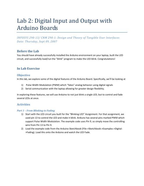
Lab 2: Digital Input and Output with Arduino Boards - Courses
Lab 2: Digital Input and Output with Arduino Boards - Courses
Lab 2: Digital Input and Output with Arduino Boards - Courses
Create successful ePaper yourself
Turn your PDF publications into a flip-book with our unique Google optimized e-Paper software.
<strong>Lab</strong> 2: <strong>Digital</strong> <strong>Input</strong> <strong>and</strong> <strong>Output</strong> <strong>with</strong><br />
<strong>Arduino</strong> <strong>Boards</strong><br />
INFOSYS 29013/ CNM 2901: Design <strong>and</strong> Theory of Tangible User Interfaces<br />
Date: Thursday, Sept 09, 2007<br />
Before the <strong>Lab</strong><br />
You should have already successfully installed the <strong>Arduino</strong> environment on your laptop, built the LED<br />
circuit, <strong>and</strong> successfully load/run the “blink” program to make the LED blink. Congratulations!<br />
In <strong>Lab</strong> Exercise<br />
Objective<br />
In this lab, we explore some of the digital features of the <strong>Arduino</strong> Board. Specifically, we’ll be looking at<br />
1) Pulse Width Modulation (PWM) which “fakes” analog behavior using digital signals<br />
2) Serial communication <strong>with</strong> the laptop allowing for greater design flexibility.<br />
In exploring these features, we will use <strong>Arduino</strong> to not just blink a single LED, but to control <strong>and</strong> fade<br />
several LEDs at once.<br />
Activities<br />
Part 1 – From Blinking to Fading<br />
1) Start <strong>with</strong> the LED circuit you built for the “Blinking LED” Assignment. For that assignment, we<br />
used pin 13 to control the LED <strong>and</strong> make it blink. Ardiuno has several pins marked PWM which<br />
support Pulse Width Modulation. The example code uses Pin 9, so simply move the controlling<br />
wire from Pin 13 to Pin 9.<br />
2) Load the example code from the <strong>Arduino</strong> Sketchbook (File‐>Sketchbook‐>Examples‐><strong>Digital</strong>‐<br />
>Fading). Load this onto the <strong>Arduino</strong> <strong>and</strong> watch the LED Fade.
Part 2 – Fading 3 LEDS<br />
3) Extend your circuit so that it includes 3 LEDs according to the diagrams below. (Sorry, all I had<br />
were green wires). Notice Pins 9, 10, <strong>and</strong> 11 are all marked PWM.<br />
4) The following code dims the 3 LEDs according to a pattern. For your convenience, a copy of the<br />
code can be downloaded from the course website. Look at the code <strong>and</strong> make sure you know<br />
what each line does.<br />
Part 3 – Serial Communications<br />
5) Up until now, the <strong>Arduino</strong> board has been operating on autopilot once you’ve uploaded the<br />
program. In this step, you will be using <strong>Arduino</strong>’s Serial Communication feature. The code is<br />
provided here <strong>and</strong> is available on the course webpage. Look at the code <strong>and</strong> make sure you<br />
know what each line does.<br />
Homework (Due Sept 13, 2007)<br />
1) Find a good diffuser for your RGB LEDs (e.g. ping pong ball, Styrofoam, etc).<br />
2) Change the code so that you can control the RGB values <strong>with</strong> multiple key presses. For example,<br />
pressing ‘r’ 5 times will set the brightness to 50% (or brightness = 127) <strong>and</strong> pressing ‘r’ 10 times<br />
will set it to 100% (or brightness = 255).<br />
3) (Optional) Come up <strong>with</strong> other ways of controlling the colors of the LEDs using the keyboard.<br />
Here’s your chance to be creative. You can show off to your friends next week. Example: Read<br />
colors <strong>and</strong> set the appropriate RGB values like “orange” might set r=70%, g=50%, <strong>and</strong> b=0%.


