Woltman meters 51 - Raminex
Woltman meters 51 - Raminex
Woltman meters 51 - Raminex

You also want an ePaper? Increase the reach of your titles
YUMPU automatically turns print PDFs into web optimized ePapers that Google loves.
<strong>Woltman</strong> <strong>meters</strong><br />
<strong>51</strong>
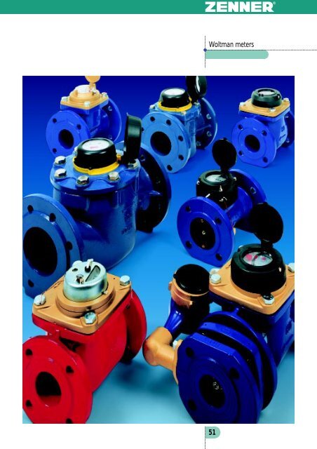
Large water <strong>meters</strong><br />
<strong>Woltman</strong> <strong>meters</strong><br />
The comprehensive range<br />
for every application<br />
ZENNER ® offers a comprehensive range of large<br />
water <strong>meters</strong>, from the various standard models<br />
to <strong>meters</strong> for special purposes.<br />
All the following series WP, WPH, WS, WPH-MF<br />
and WS-MF <strong>Woltman</strong> <strong>meters</strong> are completely dry<br />
dial <strong>meters</strong>. Only the turbine works in the wet<br />
chamber. The roller counter runs in the dry. It is<br />
encapsulated, evacuated, safe against flooding<br />
and can be rotated to any position. There is no<br />
possibility of the transparent cover becoming<br />
coated. The read-out is therefore not inhibited in<br />
any way.<br />
The head loss caused by measurement is very<br />
slight.<br />
Our <strong>Woltman</strong> <strong>meters</strong> are characterised by high<br />
long-term stability.<br />
These ZENNER ® products are based on almost<br />
100 years’ experience. Over the course of time we<br />
succeeded in developing increasingly better and<br />
resistant products. The materials for the<br />
bearings undergo continuing long-term tests<br />
under the most extreme conditions.<br />
WP<br />
the inexpensive standard model<br />
WP-N<br />
prepared for retrofitting with reed contact device<br />
or infrared pulsing device<br />
WPI-N<br />
fitted with contact or pulsing device.<br />
m the value-for-money standard meter<br />
m can be used for measuring flow rates with<br />
little fluctuation, e.g. as flow-rate <strong>meters</strong> in<br />
front of and behind pumps, and in source<br />
supply lines<br />
m Measuring insert not removable:<br />
The complete meter is replaced<br />
m Regulation on the side in the body<br />
m for cold water up to 30°C<br />
(safe up to 50°C)<br />
m for hot water up to 120°C<br />
(safe up to 150°C)<br />
m Operating pressure: PN 16<br />
m Flange bore-hole conforms to PN 10<br />
(alternative PN 16)<br />
m EC type approval in classes A and B<br />
Technical data<br />
Nom inal<br />
Maxim um<br />
flow<br />
flow<br />
Q n<br />
Qmax<br />
m ³/ h 15<br />
25<br />
40<br />
60<br />
150<br />
250<br />
m³/<br />
h 30<br />
50<br />
80<br />
120<br />
300<br />
500<br />
Max.<br />
flow short-term<br />
- m³/<br />
h 40<br />
70<br />
110<br />
180<br />
350<br />
650<br />
Permissible<br />
Transitional<br />
Minimum<br />
constant load<br />
flow<br />
flow<br />
Qn<br />
Qt<br />
Qmin<br />
m³/<br />
h 20<br />
35<br />
55<br />
90<br />
175<br />
325<br />
m³/<br />
h 3 4 8 12<br />
20<br />
50<br />
m³/<br />
h 1.<br />
2 1.<br />
2 1.<br />
2 1.<br />
8 3.<br />
5 7<br />
Start-up<br />
flow<br />
- m³/<br />
h 0.<br />
5 0.<br />
5 0.<br />
5 0.<br />
8 1.<br />
4 3. 0<br />
Flow rate<br />
with 0.1 bar head loss<br />
Nominal<br />
diameter<br />
Register range<br />
Overall<br />
Height<br />
length<br />
Flange connection<br />
according to DIN 2501<br />
- m³/<br />
h 20<br />
55<br />
65<br />
120<br />
300<br />
600<br />
DN<br />
mm<br />
50<br />
50/65<br />
80<br />
100<br />
150<br />
200<br />
- m³<br />
999.999<br />
9.999.999<br />
- l 1 10<br />
100<br />
L<br />
H<br />
mm<br />
200<br />
225<br />
250<br />
300<br />
350<br />
mm<br />
200<br />
250<br />
300<br />
350<br />
mm<br />
108<br />
125<br />
135<br />
165<br />
190<br />
h 72<br />
83<br />
95<br />
105<br />
135<br />
160<br />
D<br />
mm<br />
165<br />
185<br />
200<br />
220<br />
285<br />
340<br />
K 125<br />
145<br />
160<br />
180<br />
240<br />
295<br />
Number<br />
of screws<br />
- pcs.<br />
4 8(4)<br />
8 8(12)<br />
Weight<br />
- kg<br />
8.<br />
2 10<br />
11.<br />
6 14.<br />
8 24.<br />
8 40. 3<br />
For transitional flow Qt and minimum flow rate Qmin see table on last page of product group Multi-jet <strong>meters</strong><br />
52
m The robust device for extreme applications<br />
m Used for flow rates with little fluctuation, e.g.<br />
as a flow-rate meter in front of and behind<br />
pumps in source supply lines<br />
m Measuring insert replaceable without<br />
removing the body<br />
m Regulation at measuring insert<br />
(unlike WP version in the body)<br />
m Body made of high-quality grey cast iron<br />
m Brass sealing plate<br />
m EC type approval in classes A and B<br />
m For cold water up to 30°C (safe up to 80°C)<br />
m For hot water up to 120°C (safe up to 150°C)<br />
m Operating pressure: PN 16<br />
m Flange bore hole conforms to PN 10<br />
(alternative PN 16)<br />
m For horizontal and vertical installation<br />
m High-quality epoxy coating<br />
m DN 50 and DN 65 with improved<br />
measurements: better than class B<br />
m For recording flow rates in any direction of<br />
flow with high dynamics<br />
m Horizontal installation<br />
(vertical also possible)<br />
m Measuring insert replaceable without removing<br />
body<br />
m Regulation in the measuring insert (not in the<br />
body)<br />
m EC type approval in classes A and B<br />
m For cold water up to 30°C (safe up to 50°C)<br />
m For hot water up to 120°C (safe up to 130°C)<br />
m Operating pressure: PN 16 and PN 25<br />
m Flange bore hole conforms to PN 10<br />
m Wide measuring range for all nominal<br />
widths<br />
m Pulsing device suitable for ABB and<br />
hydrometer <strong>Woltman</strong> <strong>meters</strong><br />
<strong>Woltman</strong>zähler<br />
WPH<br />
technically advanced WP,<br />
measuring insert removable<br />
WPH-N<br />
pulse-capable for pulse outputs<br />
WPHI-N<br />
fitted with reed contact device<br />
WPH-MF-N<br />
can be retrofitted either with reed, infrared<br />
or Namur device<br />
WPH-MF<br />
is fitted with one of the above devices<br />
Nominal<br />
Maxim um<br />
flow<br />
Qmax<br />
m³/<br />
h 30<br />
50<br />
80<br />
120<br />
300<br />
500<br />
800<br />
Max.<br />
flow short-term<br />
- m³/<br />
h 70<br />
100<br />
150<br />
250<br />
350<br />
650<br />
1200<br />
Permissible<br />
Transitional<br />
Minimum<br />
constant load<br />
flow<br />
flow<br />
Qn<br />
Qt<br />
Qmin<br />
m³/<br />
h 35<br />
50<br />
90<br />
125<br />
250<br />
325<br />
600<br />
m³/<br />
h 2 5 6 6 12<br />
12<br />
20<br />
m³/<br />
h 0.<br />
7 0.75<br />
0.<br />
8 1.<br />
5 3.<br />
5 6.<br />
5 12<br />
Start-up<br />
flow<br />
- m³/<br />
h 0.25<br />
0.<br />
3 0.<br />
3 0.<br />
5 1.<br />
5 2.<br />
5 5<br />
Flow rate<br />
with 0.1 bar head loss<br />
Nominal<br />
diameter<br />
Register range<br />
Overall<br />
flow<br />
length<br />
Height WPH<br />
Height WPH-MF<br />
Flange connection<br />
according to DIN 2501<br />
Qn<br />
- m³/<br />
h 38<br />
60<br />
65<br />
100<br />
310<br />
550<br />
800<br />
DN<br />
mm<br />
50<br />
65<br />
80<br />
100<br />
150<br />
200<br />
250<br />
- m³<br />
999.999<br />
9.999.999<br />
- l 1 10<br />
L<br />
H<br />
h<br />
H<br />
h<br />
D<br />
K<br />
m³/<br />
h 15<br />
25<br />
40<br />
60<br />
150<br />
250<br />
400<br />
mm<br />
200<br />
225<br />
250<br />
300<br />
350<br />
450<br />
mm<br />
200<br />
250<br />
300<br />
350<br />
450<br />
mm<br />
148<br />
147<br />
145<br />
150<br />
210<br />
210<br />
222<br />
mm<br />
72<br />
83<br />
95<br />
105<br />
135<br />
160<br />
193<br />
mm<br />
123<br />
140<br />
212<br />
236<br />
mm<br />
75<br />
83<br />
94<br />
106<br />
135<br />
163<br />
203<br />
mm<br />
165<br />
185<br />
200<br />
220<br />
285<br />
340<br />
405<br />
mm<br />
125<br />
145<br />
160<br />
180<br />
240<br />
295<br />
350<br />
Number<br />
of screws<br />
- pcs.<br />
4 8(4)<br />
8 12<br />
8(12)<br />
12<br />
Weight<br />
WPH<br />
- kg<br />
12.<br />
6 13.<br />
2 14.<br />
2 17.<br />
7 38<br />
48.<br />
8 75<br />
Weight<br />
WPH-MF<br />
- kg<br />
10.<br />
2 11.<br />
2 14.<br />
1 19.<br />
4 32.<br />
5 45<br />
108<br />
For transitional flow Qt and minimum flow rate Qmin see table on last page of product group Multi-jet <strong>meters</strong>. WPH 125, 300, 400 and 500<br />
are available on request<br />
Technical data<br />
53
Large water <strong>meters</strong><br />
<strong>Woltman</strong> <strong>meters</strong><br />
WS<br />
robust, for extreme applications<br />
WS-N<br />
prepared for retrofitting with reed contact device<br />
or infrared pulsing device<br />
WSI-N<br />
fitted with reed or infrared measurement output<br />
m<br />
m<br />
m<br />
m<br />
m<br />
m<br />
Suitable for fluctuating flow rates;<br />
typical uses are, for example, in schools,<br />
holiday complexes and industrial plants<br />
For horizontal installation<br />
Measuring insert replaceable without removal<br />
of body<br />
Regulation in measuring insert (not in body)<br />
For cold water up to 30°C (safe up to 80°C)<br />
For hot water up to 120°C (safe up to<br />
150°C)<br />
m Operating pressure: PN 16<br />
m Flange bore-hole conforms to PN 10<br />
(alternatively PN 16)<br />
m<br />
Measurements better than class B<br />
WS-MF-N<br />
prepared for retrofitting<br />
with either reed, infrared or Namur device<br />
WS-MF<br />
fitted with one of the above pulse outputs<br />
m For counting and measuring fluctuating flow<br />
rates<br />
m For horizontal installation<br />
m Measuring insert replaceable without removal<br />
of body<br />
m Regulation in measuring insert (not in body)<br />
m EC type approval in class B<br />
m Substantially extended measuring range<br />
towards small flow rates than documented in<br />
metrology class<br />
m For cold water up to 30°C (safe up to 50°C)<br />
m For hot water up to 120°C (safe up to 130°C)<br />
m Operating pressure: PN 16<br />
m Flange bore-hole conforms to PN 10<br />
m Pulsing device suitable for ABB and<br />
hydrometer <strong>Woltman</strong> <strong>meters</strong><br />
Technical data<br />
54<br />
Nom inal<br />
Maxim um<br />
flow<br />
flow<br />
Qn<br />
Qmax<br />
m ³/ h 15<br />
25<br />
40<br />
60<br />
150 (M F)<br />
m³/<br />
h 30<br />
50<br />
80<br />
120<br />
300<br />
Max.<br />
flow short-term<br />
- m³/<br />
h 30<br />
70<br />
110<br />
180<br />
350<br />
Permissible<br />
Transitional<br />
Maximum<br />
constant load<br />
flow<br />
flow<br />
Qn<br />
Qt<br />
Qmin<br />
m³/<br />
h 20<br />
40<br />
55<br />
90<br />
200<br />
m³/<br />
h 1 3 3 5 10<br />
m³/<br />
h 0.15<br />
0.<br />
2<br />
0.<br />
2<br />
0.<br />
3<br />
0. 8<br />
Start-up<br />
flow<br />
- m³/<br />
h 0.05<br />
0.07<br />
0.07<br />
0.<br />
1<br />
0. 4<br />
Flow rate<br />
with 0.1 bar head loss<br />
Nominal<br />
diameter<br />
Register range<br />
Overall length WS<br />
Height WS<br />
Overall length WS-MF<br />
Height WS-MF<br />
Flange connection<br />
according to DIN 2501<br />
DN<br />
- m³/<br />
h 18<br />
35<br />
40<br />
60<br />
160<br />
mm<br />
50<br />
65<br />
80<br />
100<br />
150<br />
- m³<br />
999.999<br />
9.999.999<br />
- l 1 10<br />
L<br />
L<br />
H<br />
h<br />
L<br />
H<br />
h<br />
D<br />
K<br />
mm<br />
270<br />
300<br />
360<br />
-<br />
mm<br />
300<br />
300<br />
350<br />
350<br />
-<br />
mm<br />
117<br />
145<br />
150<br />
220<br />
-<br />
mm<br />
73<br />
87<br />
95<br />
105<br />
-<br />
mm<br />
270<br />
300<br />
360<br />
500<br />
mm<br />
300<br />
350<br />
500<br />
mm<br />
135<br />
202<br />
202<br />
207<br />
3<strong>51</strong><br />
mm<br />
85<br />
97<br />
102<br />
113<br />
141<br />
mm<br />
165<br />
185<br />
200<br />
220<br />
285<br />
mm<br />
125<br />
145<br />
160<br />
180<br />
240<br />
Number<br />
of screws<br />
- pcs.<br />
4 8(4)<br />
8<br />
Weight<br />
WS<br />
- kg<br />
12.<br />
7<br />
19<br />
21<br />
33<br />
-<br />
Weight<br />
WS-MF<br />
- kg<br />
14.<br />
5 24.<br />
5 25.<br />
5 31.<br />
5 79. 5<br />
For transitional flow Qt and minimum flow rate Qmin see table on last page of product group Multi-jet <strong>meters</strong>.
<strong>Woltman</strong> <strong>meters</strong><br />
FLYPPER<br />
The electronic counter module<br />
3 5 0 2 4<br />
S.R.D.<br />
l/h<br />
remote read-out<br />
m³<br />
Register of<br />
current volume<br />
8 8 8 8 8 8 8 8 m³<br />
S.R.D.<br />
l/h<br />
remote read-out<br />
Register self-test<br />
All segments on<br />
S.R.D.<br />
l/h<br />
m³<br />
Register self-test<br />
All segments off<br />
remote read-out<br />
2 5 0 0 1<br />
S.R.D.<br />
l/h<br />
remote read-out<br />
m³<br />
Volume register<br />
on S.R.D. (Specified<br />
reading date)<br />
3 1 - 1 0 - 9 9<br />
S.R.D.<br />
l/h<br />
m³<br />
Specified reading<br />
date<br />
remote read-out<br />
1 5 0 2 0<br />
S.R.D.<br />
l/h<br />
m³<br />
Current<br />
flow rate<br />
remote read-out<br />
Previously it was very time-consuming and<br />
costly to read <strong>meters</strong> and document the results.<br />
Extensive lists of addresses had to be “combed<br />
through“ and <strong>meters</strong> had to be read in flooded<br />
manholes or other locations which are difficult to<br />
access. Under such aggravating conditions,<br />
incorrect readings cannot be ruled out either, and<br />
incorrect entries can also result when data is<br />
being processed.<br />
Today such sources of error can be avoided and<br />
the data reading can be realized quickly and<br />
economically. With the FLYPPER module it is<br />
no longer necessary to access man holes. A<br />
special seal in the devices guarantees flooding<br />
safety to protection type IP 68. The data can<br />
then, for example, be recorded and stored via<br />
the M-Bus socket at the top of the manhole<br />
directly in the laptop.<br />
S.R.D.<br />
l/h<br />
remote read-out<br />
S.R.D.<br />
l/h<br />
remote read-out<br />
S.R.D.<br />
l/h<br />
remote read-out<br />
- 0 2 5<br />
A 1 2 5<br />
3 0 0 2 4<br />
m³<br />
m³<br />
m³<br />
Days since last<br />
remote read-out<br />
Number of<br />
remote read-outs<br />
Volume of last<br />
remote read-out<br />
connection box<br />
Ed2Kl6.3<br />
Can also be combined with multidata S1<br />
and pulse counter module in M-Bus networks<br />
from ZENNER<br />
It is also possible to use the<br />
PSION workabout ®<br />
as a read-out system.<br />
55
Large water <strong>meters</strong><br />
<strong>Woltman</strong> <strong>meters</strong><br />
Combination <strong>meters</strong><br />
WPV-MF-N<br />
New: very large measuring range:<br />
DN 50 15 - 30.000 l/h<br />
DN 80 16 - 80.000 l/h<br />
DN 100 15 - 120.000 l/h<br />
DN 150 30 - 300.000 l/h<br />
WPV-N<br />
Combination <strong>meters</strong> are designed to record water<br />
volumes with very high or very low flow<br />
rates. In the event of fire, for example, at a<br />
tap position where normally only very small<br />
quantities of water are drawn per unit time, a<br />
high flow rate is required. In this event, the<br />
switching valve opens and the volume which has<br />
flowed through is recorded by the larger meter.<br />
Our combination <strong>meters</strong> are characterised by<br />
high accuracy of measurement even in the<br />
switch-over range, as well as by minimum head<br />
loss at maximum load. They are simple in design,<br />
durable in operation and are relatively light in<br />
weight.<br />
One further benefit is their overall length which<br />
is identical with the standard WS <strong>meters</strong>, which<br />
are also used here. This series thus offers every<br />
advantage of the WS series.<br />
Both types can be extended with the adjustable<br />
adapter piece. It is available in sizes DN 50-150.<br />
The main meter is a dry dial meter in each case,<br />
while the small auxiliary meter is a wet dial meter.<br />
Looking in the direction of flow, the auxiliary<br />
meter is fitted to the right of the main meter or<br />
alternatively in special designs to the left. The<br />
auxiliary meter is better than class C.<br />
The combination <strong>meters</strong> are intended for use<br />
with cold water up to 30°C.<br />
The fitting position is horizontal. The maximum<br />
operating pressure is 16 bar. The flanges are<br />
bored to DIN 2501; PN 10.<br />
All <strong>meters</strong> have EC type approval and are<br />
certified to EO6.<br />
Model IP 68 is designed for installation in the<br />
manhole. The counter is safe against flooding.<br />
NEW: TURBO VERBUND<br />
see Special Brochure<br />
56<br />
adjustable adapter piece
Main meter<br />
Secondary meter<br />
Nominal<br />
N om inal<br />
Maxim um<br />
flo w<br />
flo w<br />
Q n<br />
Qmax<br />
Register<br />
range<br />
-<br />
Nominal<br />
flow<br />
Qn<br />
Register<br />
range<br />
-<br />
diameter<br />
DN<br />
m ³/ h 15<br />
4 0<br />
6 0<br />
15 0<br />
m³/<br />
h 30<br />
80<br />
120<br />
300<br />
m³<br />
999.999<br />
9.999.999<br />
l 1 10<br />
m³/<br />
h<br />
2.<br />
5<br />
10<br />
m³<br />
99.999<br />
l 0.05<br />
mm<br />
50<br />
80<br />
100<br />
150<br />
Overall<br />
length<br />
L m m 270<br />
(300)<br />
300<br />
(350)<br />
360<br />
(350)<br />
500<br />
± 15<br />
Width<br />
Height<br />
B<br />
b<br />
H<br />
h<br />
mm<br />
185<br />
200<br />
215<br />
295<br />
mm<br />
95<br />
110<br />
125<br />
150<br />
mm<br />
220<br />
240<br />
255<br />
354<br />
mm<br />
75<br />
95<br />
105<br />
135<br />
Flange<br />
connection<br />
K mm<br />
125<br />
160<br />
180<br />
240<br />
Screw<br />
hole diameter<br />
l mm<br />
18<br />
22<br />
Number<br />
of screws<br />
- pcs.<br />
4 8(4)<br />
8<br />
Switch-over flow<br />
- m³/<br />
h<br />
1.<br />
6<br />
2.<br />
5<br />
6. 2<br />
- m³/<br />
h<br />
1.<br />
1<br />
1.<br />
9<br />
4. 8<br />
Weight<br />
- kg<br />
19<br />
24<br />
30<br />
75<br />
For transitional flow Qt and minimum flow rate Qmin see table on last page of product group Multi-jet <strong>meters</strong>.<br />
<strong>Woltman</strong> <strong>meters</strong><br />
Technical data WPV<br />
Main meter<br />
Secondary meter<br />
Nominal<br />
Nominal<br />
Maximum<br />
flow<br />
flow<br />
Qn<br />
Qmax<br />
Register<br />
range<br />
-<br />
Nominal<br />
flow<br />
Qn<br />
Register<br />
range<br />
-<br />
diameter<br />
DN<br />
m³/<br />
h 15<br />
40<br />
60<br />
150<br />
m³/<br />
h 30<br />
80<br />
120<br />
300<br />
m³<br />
999.999<br />
9.999.999<br />
l 1 10<br />
m³/<br />
h<br />
2.<br />
5<br />
10<br />
m³<br />
99.999<br />
l 0.05<br />
mm<br />
50<br />
80<br />
100<br />
150<br />
Overall<br />
length<br />
L mm<br />
270<br />
300<br />
350<br />
/ 360<br />
500<br />
± 15<br />
Width<br />
Height<br />
B<br />
b<br />
H<br />
h<br />
mm<br />
190<br />
220<br />
290<br />
mm<br />
85<br />
110<br />
110<br />
145<br />
mm<br />
198<br />
234<br />
246<br />
347<br />
mm<br />
75<br />
94<br />
106<br />
135<br />
Flange<br />
connection<br />
K mm<br />
125<br />
160<br />
180<br />
240<br />
Screw<br />
hole diameter<br />
l mm<br />
18<br />
22<br />
Number<br />
of screws<br />
- pcs.<br />
4 8(4)<br />
8<br />
Switch-over flow<br />
- m³/<br />
h<br />
1.<br />
9<br />
2.<br />
8<br />
6. 2<br />
- m³/<br />
h<br />
1.<br />
2<br />
1.<br />
6<br />
4. 8<br />
Weight<br />
- kg<br />
17.<br />
4<br />
25.<br />
4<br />
32/33<br />
68<br />
Technical data WPV-MF<br />
For transitional flow Qt and minimum flow rate Qmin see table on last page of product group Multi-jet <strong>meters</strong>.<br />
Head loss curves<br />
57
Large water <strong>meters</strong><br />
<strong>Woltman</strong> <strong>meters</strong><br />
WI<br />
Irrigation meter for sprinkling<br />
fresh and dirty water<br />
Well meter<br />
Heavily soiled water, e.g. in agriculture, sewage<br />
treatment plants or waste-water processing plants,<br />
requires particularly robust <strong>meters</strong>.<br />
The measuring insert is fitted in the top area of<br />
the pipe, where there are mostly only a few<br />
suspended particles in the water which flows<br />
through. The <strong>Woltman</strong> irrigation meter can thus<br />
even function in water containing up to 30%<br />
pollution.<br />
The irrigation meter is, however, also frequently<br />
used for fresh water as a control meter where<br />
flow rates fluctuate little. It is the ideal low-speed<br />
well meter. Irrespective of the power supply, it is<br />
the cost-effective alternative to induction<br />
flow <strong>meters</strong>.<br />
The WI is a dry dial meter with magnetic<br />
coupling. It can also be installed in pipes which<br />
run vertically or horizontally.<br />
However, a filter is recommended for soiled<br />
water.<br />
The roller counter is encapsulated and can be<br />
secured with a padlock. The removable<br />
measuring insert is the same for all sizes.<br />
Model WI-I has the same design as model WI, but<br />
is fitted with a reed switch.<br />
Measuring accuracy<br />
Qmax-Qt: ± 3% (class A+B values)<br />
Qt-Qmin: ± 5% (class A values)<br />
Flange bore hole to DIN 2532,<br />
DIN 2501 PN10<br />
Pulse values:<br />
0.1, 1, 10 m³/Impuls<br />
Operating pressure:<br />
1.6 MPa<br />
16 bar<br />
Technical data<br />
Nom inal<br />
M ax. load<br />
flow<br />
Transitional flow<br />
Minimum<br />
Nominal<br />
flow<br />
diameter<br />
Register range<br />
short-term<br />
Class<br />
Class<br />
Class<br />
A<br />
B<br />
A<br />
Qn<br />
Qm ax<br />
Qmax<br />
Qt<br />
Qt<br />
Qmin<br />
DN<br />
m ³/ h 30<br />
50<br />
90<br />
125<br />
175<br />
250<br />
450<br />
m³/<br />
h 70<br />
120<br />
300<br />
500<br />
800<br />
m³/<br />
h 100<br />
120<br />
150<br />
300<br />
350<br />
500<br />
900<br />
m³/<br />
h 9 18<br />
45<br />
75<br />
120<br />
m³/<br />
h 6 12<br />
30<br />
50<br />
80<br />
m³/<br />
h 2.<br />
4<br />
4.<br />
8<br />
12<br />
20<br />
32<br />
mm<br />
50<br />
65<br />
80<br />
100<br />
125<br />
150<br />
200<br />
- m³<br />
10<br />
7<br />
- m³<br />
0.005<br />
Overall<br />
length<br />
L mm<br />
200<br />
200<br />
225<br />
250<br />
250<br />
300<br />
350<br />
Height<br />
h<br />
H<br />
mm<br />
75<br />
85<br />
95<br />
105<br />
120<br />
135<br />
180<br />
mm<br />
230<br />
240<br />
250<br />
260<br />
275<br />
305<br />
335<br />
Weight<br />
- kg<br />
11<br />
12<br />
14<br />
18<br />
22<br />
27<br />
40<br />
58
The reed switch (low frequency switch) supplies<br />
a low-resolution pulse frequency in proportion<br />
to the flow rate in combination with the counter<br />
of the water meter and the magnets, which are<br />
installed as standard. The reed switch is used<br />
for the remote counting and registration of<br />
through-flowing volumes of water by means of<br />
the summarizing electronic pulse output counter,<br />
printer or memory. It can be connected to the<br />
IZM 972 pulse counter module and can thus be<br />
integrated into M-Bus networks. Type KG-ZR is<br />
suitable for series WPHI-N and WSI-N <strong>Woltman</strong><br />
<strong>meters</strong>. Series KG-R functions in exactly the same<br />
way as KG-ZR, but has been specially developed<br />
for the <strong>Woltman</strong>-MF series<br />
Low-resolution contact device<br />
Reed switch<br />
KG-ZR<br />
KG-R<br />
Contact load:<br />
Cable:<br />
Cable length:<br />
24 V, 0.2 A<br />
2 x 0.25 mm²<br />
2 m<br />
KG-ZR für Bauart N<br />
KG-R für Bauart MF<br />
Together with the initiator, which is fitted as<br />
standard in the counter, the pulsing device (lowfrequency<br />
switch) a high-resolution pulse<br />
frequency proportionate to the flow rate. An<br />
infrared light beam serves as the pulsing device,<br />
and a reflecting strip embossed onto the wheel<br />
disc serves as the initiator. The pulsing device can<br />
be connected to a measuring signal converter<br />
which supplies analog flow rate values, e.g. for<br />
monitoring breaks in the pipework, for controlling<br />
pumps and slide valves or for dosing quantities.<br />
Version IG-ZR is suitable for series WPHI-N and<br />
WSI-N <strong>Woltman</strong> <strong>meters</strong>. Series IG-IR has the<br />
identical function as IG-ZR, but has been specially<br />
developed for the <strong>Woltman</strong>-MF series. The Namur<br />
receiver (IG-IN) is available for all version WPH-<br />
MF and WS-MF <strong>Woltman</strong> <strong>meters</strong>.<br />
High-resolution pulsing device<br />
IR light beam / Namur device<br />
IG-ZR<br />
IG-IR<br />
IG-IN<br />
Triple-conductor<br />
version:<br />
3 x 0.25 mm²<br />
Cable length: 2 m<br />
IG-ZR for type N IG-IR for type MF IG-IN for type MF<br />
KG-ZR<br />
KG-R<br />
IG-ZR<br />
IG-IR<br />
IG-IN<br />
W PH<br />
W P<br />
- - - - -<br />
W S<br />
WPH-N<br />
WP-N<br />
m m<br />
WS-N<br />
WPH-MF-N<br />
WS-MF-N<br />
WPHI-N<br />
WPI-N<br />
l l<br />
WSI-N<br />
WPH-MF<br />
WS-MF<br />
m m m<br />
l l l<br />
- not retrofittable m retrofittable l retrofitted<br />
Pulse<br />
rate 10<br />
100<br />
1000<br />
10000<br />
D N 50 ² ü ü<br />
D N 65 ² ü ü<br />
D N 80 ² ü ü<br />
DN<br />
100<br />
ü ü<br />
DN<br />
125<br />
ü ü<br />
D N 150<br />
² ü ü<br />
D N 200<br />
² ü ü<br />
D N 250<br />
² ü ü<br />
DN<br />
300<br />
ü ü<br />
DN<br />
400<br />
ü ü<br />
ü possible version ² special version for KG-R<br />
Retrofit options<br />
and pulse values<br />
WPH-N, WPHI-N, WPH-MF-N,<br />
WSI-N and WS-MF-N<br />
for KG-ZR / KG-R contact devices<br />
WS up to DN 100 only<br />
WP up to DN 200 only<br />
59
Large water <strong>meters</strong><br />
Installation<br />
Contact device<br />
Contact and pulsing devices<br />
Type WPI-N / WSI-N<br />
Remove the customer seal, unscrew the four<br />
screws in the protective covering and take off the<br />
protective cap. Slide the contact device into the<br />
shaft provided in the protective cap, feed the<br />
cable outwards through the opening and<br />
reassemble in reverse order.<br />
Pulser<br />
Type WPHI-N<br />
Remove the customer seal, unscrew the two<br />
screws in the covering and take off the protective<br />
cap. Slide the contact device into the shaft<br />
provided in the mounting ring, feed the cable<br />
outwards through the opening and reassemble in<br />
reverse order.<br />
Combined<br />
honeycomb rectifier<br />
Perfect measuring results in <strong>Woltman</strong> <strong>meters</strong><br />
require that the water strikes the meter at a steady<br />
flow.<br />
In order to prevent excessive turbulence in<br />
flow, stabilizing sections in front of the <strong>meters</strong><br />
are prescribed. This task is also carried out by<br />
the flow straighteners which are fitted in front of<br />
and behind the meter.<br />
Should, however, an irregular rate of flow occur<br />
in the pipe cross section, other or additional<br />
measures must be taken so that the result of<br />
the measurement is not falsified. This problem<br />
occurs if a meter is installed immediately after a<br />
vavle bend in the pipe or if several pumps feed<br />
one collecting pipe.<br />
A honeycomb rectifier solves this problem.<br />
32 square axial-flow channels destroy the angular<br />
momentum of the water inside the pipeline.<br />
Located at the inlet of the honeycomb section<br />
is a perforated disc whose cross section is<br />
approximately half the size of the cross section<br />
of the pipe. The inflowing water is damped and<br />
the square channels which follow destroy any angular<br />
momentum.<br />
The head loss caused by the honeycomb rectifier<br />
at a flow rate of 3 m/sec is approximately 0.1 bar.<br />
The metal flange on the perforated disc is used<br />
to secure the rectifier between two flanges with<br />
the honeycomb section pointing in the direction<br />
of flow. A length of blank pipe at least 5 pipe<br />
dia<strong>meters</strong> should be fitted in front of the meter.<br />
If the rectifier is positioned at a short distance in<br />
front of the meter then minus-range deviations<br />
in measurements can occur.<br />
The honeycomb rectifier is made of stainless<br />
steel.<br />
DN 50 - 500 mm<br />
∅ holding flange - ∅ sealing strip<br />
60
Meters ordering data<br />
M odel<br />
N om inal flo w<br />
rate m ³/h<br />
D N<br />
O verall leng th<br />
Pulse<br />
rate<br />
T ype<br />
O rder no.<br />
W PH-N *<br />
PN 10/16, 30°C<br />
WPHI-N<br />
PN 10/16, 30°C<br />
WPH<br />
PN 10/16, 30°C<br />
WPH-MF-N *<br />
PN 25/40, 30°C<br />
WPH-MF-N *<br />
PN 10/16, 90°C<br />
15<br />
50<br />
200<br />
m m selectable<br />
W PH I-K-050<br />
12B 001<br />
25<br />
65<br />
200<br />
mm<br />
selectable<br />
WPHI-K-65<br />
12B 002<br />
40<br />
80<br />
225<br />
mm<br />
selectable<br />
WPHI-K-80<br />
12B 003<br />
60<br />
100<br />
250<br />
mm<br />
selectable<br />
WPHI-K-100<br />
12B 004<br />
150<br />
150<br />
300<br />
mm<br />
selectable<br />
WPHI-K-150<br />
12B 005<br />
250<br />
200<br />
350<br />
mm<br />
selectable<br />
WPHI-K-200<br />
12B 006<br />
400<br />
250<br />
450<br />
mm<br />
selectable<br />
WPHI-K-250<br />
12B 007<br />
15<br />
50<br />
200<br />
mm<br />
1000<br />
WPHI-IK-050<br />
12B 008<br />
15<br />
50<br />
200<br />
mm<br />
WPH-K-050<br />
12B 009<br />
15<br />
50<br />
200<br />
mm<br />
selectable<br />
WPH-MF-050<br />
12B 010<br />
15<br />
50<br />
200<br />
mm<br />
selectable<br />
WPH-MF-050<br />
12B 011<br />
WPH-N<br />
Standard version<br />
available up to DN 500<br />
Pulse version<br />
complete with contact device KG-ZR (example)<br />
Pulsing device cannot be retrofitted<br />
WS-N *<br />
PN 10/16, 30°C<br />
WSI-N<br />
PN 10/16, 30°C<br />
15<br />
50<br />
270<br />
mm<br />
selectable<br />
WSI-K-050<br />
11B 001<br />
25<br />
65<br />
300<br />
mm<br />
selectable<br />
WSI-K-065<br />
11B 002<br />
40<br />
80<br />
300<br />
mm<br />
selectable<br />
WSI-K-080<br />
11B 003<br />
60<br />
100<br />
360<br />
mm<br />
selectable<br />
WSI-K-100<br />
11B 004<br />
150<br />
150<br />
500<br />
mm<br />
selectable<br />
WSI-K-150<br />
11B 005<br />
15<br />
50<br />
270<br />
mm<br />
1000<br />
WSI-IK-050<br />
11B 006<br />
WS<br />
15<br />
50<br />
270<br />
mm<br />
WS-K-050<br />
11B 009<br />
WS-MF-N *<br />
PN 25/40, 30°C<br />
WS-MF-N *<br />
PN 10/16, 90/120°C<br />
15<br />
50<br />
270<br />
mm<br />
WS-MF-050<br />
11B 007<br />
15<br />
50<br />
270<br />
mm<br />
WS-MF-050<br />
11B 008<br />
WP<br />
15<br />
50<br />
200<br />
mm<br />
WP-K-050<br />
10B 001<br />
WP-N<br />
15<br />
50<br />
200<br />
mm<br />
selectable<br />
WPI-K-050<br />
10B 002<br />
WPI-N<br />
15<br />
50<br />
200<br />
mm<br />
1000<br />
WPI-IK-050<br />
10B 003<br />
WI<br />
PN 10/16, 50°C<br />
65<br />
200<br />
mm<br />
WI-K-065<br />
14B 001<br />
80<br />
225<br />
mm<br />
WI-K-080<br />
14B 002<br />
100<br />
250<br />
mm<br />
WI-K-100<br />
14B 003<br />
125<br />
250<br />
mm<br />
WI-K-125<br />
14B 004<br />
150<br />
300<br />
mm<br />
WI-K-150<br />
14B 005<br />
200<br />
350<br />
mm<br />
WI-K-200<br />
14B 006<br />
WI-I<br />
50<br />
65<br />
200<br />
mm<br />
1000<br />
WI-IK-065<br />
14B 007<br />
WPV-N<br />
PN 10/16, 30°C<br />
WPV-MF-N<br />
PN 10/16, 30°C<br />
**<br />
15<br />
50<br />
270<br />
mm<br />
WPV-N-050<br />
15B 001<br />
**<br />
40<br />
80<br />
300<br />
mm<br />
WPV-N-080<br />
15B 002<br />
*<br />
60<br />
*<br />
150<br />
*<br />
00<br />
*<br />
50<br />
1 350/360<br />
mm<br />
WPV-N-100<br />
15B 003<br />
1 500<br />
±15 mm<br />
WPV-N-150<br />
15B 004<br />
250<br />
200<br />
1200<br />
mm<br />
WPV-N-200<br />
15B 005<br />
15<br />
50<br />
270<br />
mm<br />
WPV-MF-N-050<br />
15B 006<br />
40<br />
80<br />
300<br />
mm<br />
WPV-MF-N-080<br />
15B 007<br />
60<br />
100<br />
350/360<br />
mm<br />
WPV-MF-N-100<br />
15B 008<br />
150<br />
150<br />
500<br />
±15 mm<br />
WPV-MF-N-150<br />
15B 009<br />
* pulsing device can be retrofitted; please state pulse sequence and type of device beforehand; we will be pleased to advise you<br />
** in factory-tested version<br />
all MF series also available with FLYPPER counter; other lengths and pulse sequences also available to suit all sizes<br />
WS-N<br />
Standard version<br />
Pulse version up to DN 150<br />
complete with contact device KG-ZR (example)<br />
Pulsing device cannot be retrofitted<br />
Pulsing device can be retrofitted, but<br />
PN 25/40, available up to DN 150<br />
Pulsing device can be retrofitted, but<br />
90°C, available up to DN 150<br />
WP, WP-N, WPI-N<br />
available up to DN 250<br />
WI<br />
Pulsing device cannot be retrofitted<br />
complete with pulsing device,<br />
available up to DN 200<br />
WPV<br />
without adapter piece<br />
with adapter piece<br />
WPV-MF<br />
without adapter piece<br />
61
Large water <strong>meters</strong><br />
Accessories ordering data<br />
M odel<br />
Q ty. in<br />
pack age<br />
D N<br />
O verall leng th<br />
T ype<br />
O rder no.<br />
Adjustable<br />
spacer<br />
1<br />
50<br />
327<br />
±20 mm<br />
BWA-050<br />
65B 001<br />
80<br />
397<br />
±40 mm<br />
BWA-080<br />
65B 002<br />
100<br />
442<br />
±25 mm<br />
BWA-100<br />
65B 003<br />
150<br />
500<br />
mm<br />
BWA-150<br />
65B 004<br />
Reed contact device for model N<br />
Reed<br />
contact device for model MF<br />
1<br />
KG-ZR<br />
65B 005<br />
KG-R<br />
65B 006<br />
Model N<br />
Model MF<br />
Infred pulser for model N<br />
Infred<br />
pulser for model MF<br />
1<br />
IG-ZR<br />
65B 007<br />
IG-IR<br />
65B 008<br />
Model N<br />
Model MF<br />
Inductive<br />
Namur device for model MF 1 IG-IN<br />
65B 009<br />
Model MF<br />
Combined<br />
honeycomb rectifier<br />
1<br />
50<br />
WGR-050<br />
65B 010<br />
65<br />
WGR-065<br />
65B 011<br />
80<br />
WGR-080<br />
65B 012<br />
100<br />
WGR-100<br />
65B 013<br />
125<br />
WGR-125<br />
65B 014<br />
150<br />
WGR-150<br />
65B 015<br />
200<br />
WGR-200<br />
65B 018<br />
Filter<br />
for <strong>Woltman</strong> meter<br />
1<br />
50<br />
200<br />
FWZ-050<br />
65B 019<br />
80<br />
225<br />
FWZ-080<br />
65B 020<br />
100<br />
250<br />
FWZ-100<br />
65B 021<br />
62