
You also want an ePaper? Increase the reach of your titles
YUMPU automatically turns print PDFs into web optimized ePapers that Google loves.
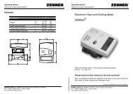
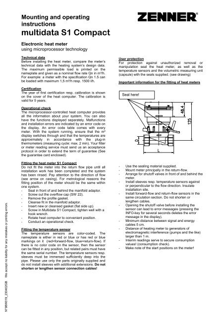
Mounting and operatinginstructions<strong>multidata</strong> <strong>S1</strong> <strong>Compact</strong>Electronic heat meterusing microprocessor technologyTechnical dataBefore installing the heat meter, compare the meter’stechnical data with the heating system’s design data.The maximum permissible load is printed on thenameplate and given as a nominal flow rate Qn in m³/h.For example: a meter with the specification Qn 1.5 canbe loaded with maximum 1,5 m³/h resp. 1500 l/h.CertificationThe year of first certification resp. calibration is shownon the cover of the heat computer. The calibration isvalid for 5 years.User protectionFor protection against unauthorized removal ormanipulation seal the heat meter, as well as thetemperature sensors and the volumetric measuring unit(capsule) with the seals supplied. (see drawing)Important information for the fitting of heat metersSeal here!N°98W019_230402GB We accept no liability for any mistakes or printing errors.Operational checkThe microprocessor-controlled heat computer providesall the information about your system. You can alsohave the functions displayed separately. Malfunctionsand installation errors are indicated by an error code onthe display. An error code table comes with everymeter. With the system running, ensure that the m³display switches through and that the temperatures areapproximately in accordance with the plug-inthermometers (measuring cycle: max. 2 min). Your fitteror meter reading service must send us an acceptanceprotocol in order to extend the term of guarantee (Seethe guarantee card enclosed).Fitting the heat meter <strong>S1</strong> <strong>Compact</strong>Do not fit the meter into the return flow pipe until allinstallation work has been completed and the systemhas been rinsed. Pay attention to the direction of flow(see arrow on casing). For metrological reasons thefitting position of the meter should be the same withinone system.- Seal in front of and behind the manifold adaptor.- Screw out the overflow cap (SW 22).- Remove the profile gasket.- Cleanse fit in the manifold adaptor.- Insert new or cleansed gasket (flat side up).- Screw in Multidata <strong>S1</strong> <strong>Compact</strong>, tighten well with ahook wrench.- Rotate heat computer to convenient position.- Conduct an operational check.Fitting the temperature sensorThe temperature sensors are color-coded. Thenameplate is either in red or blue or has red or bluemarkings on it (red=forward-flow, blue=return-flow). Ifthere is no color code on the sensor, then the sensorcan be fitted in any position, but related pairs must havethe same serial number. The temperature sensors resp.sleeves must be immersed sufficiently deep into thepipe. Please use only the parts originally supplied anddo not install sleeves with additional extensions. Do notshorten or lengthen sensor connection cables!- Use the sealing material supplied.- Mount meter principally in the return-flow.- Arrange for shutoff valves in front of and behind themeter.- Install sleeves resp. temperature sensors againstor perpendicular to the flow direction. Insulateinstallation site.- Install forward-flow and return-flow sensors in thesame circulation section. Do not shorten orlengthen cables.- Opening the shutoff valve before installing thesensor can lead to error messages (pressing theINFO-key for several seconds deletes the errormessage in the display).- Minimum distance between signal and energycables 5 cm.- Distance of heating meter to generators ofelectromagnetic interference (pumps and the like)larger than 1 m.- Interim readings serve to secure consumptionvalues! (consumption check).- Make note of the start positions on the meter!
Mounting and operatinginstructions<strong>multidata</strong> <strong>S1</strong> <strong>Compact</strong>Error code tableErrorRemedyErr 00100 Volume 1 frequency too large Correct the systemErr 00062Err 00063Check sensor and connections,Wrong temperature sensorErr 00064and replace if necessaryErr 00065Err 00071 Sensors wrong way round Correct the systemErr 00034 Short circuit temperature sensor return-flowErr 00044 Short circuit temperature sensor forward-flowErr 00037 Return-flow sensor interruptionCheck sensor and connections,and replace if necessaryErr 00047 Forward-flow sensor interruptionErr 000xx Other errors in temperature measurementErr > 1000 Internal error Only at service company / factoryMenusQ = Total energy in kWh/MWh Self reading code - = Temperature differenceV = Water quantity volume 1 in l/m³ Segment test display m³/h = current flow rate1 = Volume external meter 1 in m³ = Forward-flow temperature W = current energy consumption2 = Volume external meter 2 in m³ = Return-flow temperature h = hours operatingBasic setting:Use:Service-Program:Control:Error display:Display kWh (MWh) or error (Err...)Pressing the „Info“ key, switches the menu according to the diagram above. After a few momentsthe basic setting is again displayed.Service technicians and meter-reading companies can reach other menu levels, for example, testday. Ask our factory for information sheets about this.A turbine symbol * (asterisk) in the upper left hand corner of the LCD-display appears with everypulse from the volumetric measuring unit and can be used as a functional check.If there are error messages, these appear in front of the energy display until the error is corrected.Pressing the „Info“ key for several seconds will delete the error in the display.Connection terminalsAttentionOnly direct measuring sensors with the registration mark22.30/84.07 (see type label) should be used wheninstalling the return-flow sensor in the measuring capsule.No particular type resp. registration is required if forwardflow,as well as return-flow sensors are installed outside ofthe measuring capsule.Package contents: 1 compact heat meter / 1 sealing set / 1 profile gasket for the manifold adaptorcasingZENNER GmbH & Co. KGaARömerstadt 4 Tel.: 0681 / 9 96 76-0 info@zenner.deD - 66121 Saarbrücken Fax: 0681 / 6 43 94 http://www.zenner.de