Synthetic Inflow Condition for Large Eddy Simulation (Synthetic - KTH
Synthetic Inflow Condition for Large Eddy Simulation (Synthetic - KTH
Synthetic Inflow Condition for Large Eddy Simulation (Synthetic - KTH

Create successful ePaper yourself
Turn your PDF publications into a flip-book with our unique Google optimized e-Paper software.
u ′<br />
(j) =<br />
N�<br />
k=−N<br />
CHAPTER 2. BACKGROUND<br />
bkr(j + k) (2.36)<br />
with bk, the filter coefficients, N, connected to the support of the filter and<br />
r(j + k), the random number generated at point (j + k) with a normal distribution<br />
ℵ(0, 1). Thus the two-point correlations between points j and (j + m) depend on<br />
the filter choice and read<br />
< u ′<br />
(j)u ′<br />
(j + m) >=<br />
N�<br />
k=−N+m<br />
bkbk−m<br />
(2.37)<br />
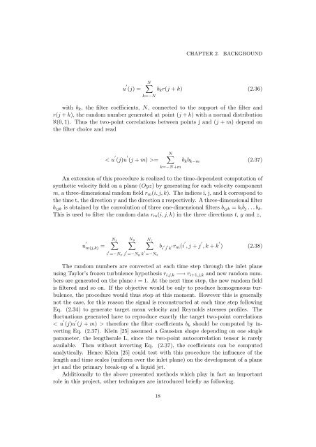
An extension of this procedure is realized to the time-dependent computation of<br />
synthetic velocity field on a plane (Oyz) by generating <strong>for</strong> each velocity component<br />
m, a three-dimensional random field rm(i, j, k). The indices i, j, and k correspond to<br />
the time t, the direction y and the direction z respectively. A three-dimensional filter<br />
bijk is obtained by the convolution of three one-dimensional filters bijk = bi ˙ bj . . . bk.<br />
This is used to filter the random data rm(i, j, k) in the three directions t, y and z,<br />
u ′<br />
m(j,k) =<br />
Nx �<br />
Ny �<br />
Nz �<br />
i ′ =−Nx j ′ =−Ny k ′ =−Nz<br />
b i ′ j ′ k ′ rm(i ′<br />
, j + j ′<br />
, k + k ′<br />
) (2.38)<br />
The random numbers are convected at each time step through the inlet plane<br />
using Taylor’s frozen turbulence hypothesis ri,j,k −→ ri+1,j,k and new random numbers<br />
are generated on the plane i = 1. At the next time step, the new random field<br />
is filtered and so on. If the objective would be only to produce homogeneous turbulence,<br />
the procedure would thus stop at this moment. However this is generally<br />
not the case, <strong>for</strong> this reason the signal is reconstructed at each time step following<br />
Eq. (2.34) to generate target mean velocity and Reynolds stresses profiles. The<br />
fluctuations generated have to reproduce exactly the target two-point correlations<br />
< u ′<br />
(j)u ′<br />
(j + m) > there<strong>for</strong>e the filter coefficients bk should be computed by inverting<br />
Eq. (2.37). Klein [25] assumed a Gaussian shape depending on one single<br />
parameter, the lengthscale L, since the two-point autocorrelation tensor is rarely<br />
available. Then without inverting Eq. (2.37), the coefficients can be computed<br />
analytically. Hence Klein [25] could test with this procedure the influence of the<br />
length and time scales (uni<strong>for</strong>m over the inlet plane) on the development of a plane<br />
jet and the primary break-up of a liquid jet.<br />
Additionally to the above presented methods which play in fact an important<br />
role in this project, other techniques are introduced briefly as following.<br />
18