Installation Instructions - Trinity Highway Products, LLC
Installation Instructions - Trinity Highway Products, LLC
Installation Instructions - Trinity Highway Products, LLC

You also want an ePaper? Increase the reach of your titles
YUMPU automatically turns print PDFs into web optimized ePapers that Google loves.
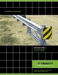
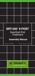
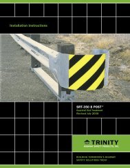
CAT ® -350<br />
Crash Cushion<br />
Attenuating Terminal<br />
Assembly Manual<br />
Part No. 620291B<br />
Revised February 2005
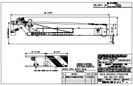
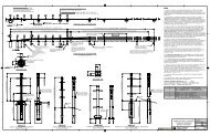
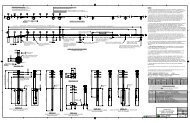
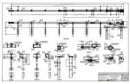
FOR SPECIFIC DETAILS, REFER TO THE CAT-350 TM<br />
DRAWING(S) AND<br />
THE STATE STANDARD DRAWING(S)<br />
CAT-350 TM<br />
(This represents the CAT-350 TM system with 6 short tubes with soil plates)<br />
NOTES:<br />
Alternates to the 6 short tubes with soil plates are:<br />
1. Six (6) long tubes with no soil plates.<br />
2. Any combination of long tubes and short tubes with soil plates<br />
3. Two (2) long tubes at Posts 1 and 2 and four (4) CRT posts at Posts 3 through 6.<br />
4. Two (2) short tubes with soil plates at Posts 1 and 2 and four (4) CRT posts at Posts 3<br />
through 6.<br />
Alternate to the channel strut is the angle strut.
CAT- 350 TM BILL OF MATERIAL<br />
ENGLISH (METRIC)<br />
(FOR SPECIFIC MATERIALS AND QUANTITIES, SEE STATE’S OPTION(S))<br />
PN QTY DESCRIPTION<br />
31G 2 12/12.5' (2.67/3.81) CAT (GUARDRAIL)<br />
130A 2 10/12.5"/5’10:6’8/SP (3.43/3810/SP) CAT (GUARDRAIL)<br />
705G 1 PIPE SLEEVE - 2" STD PIPE x 5 1/2” (50 STD PIPE x 140)<br />
740G V 6" x 8" x 4’6" x 3/16” (152 x 203 x 1375 x 4.8) TUBE SLEEVE<br />
749G V 6" x 8" x 6’0" x 3/16” (152 x 203 x 1830 x 4.8) TUBE SLEEVE<br />
(ALTERNATE TO USING 740G AND 769G)<br />
769G V 18" x 24" x 1/4” (460 x 610 x 6) SOIL PLATE<br />
782G 1 8" x 8" x 5/8” (200 x 200 x 16) BEARING PLATE<br />
983G 1 10 (3.43)/NOSE PLATE/ CAT/ ROLLED<br />
984G 2 10 (3.43)/SIDE PLATE CAT<br />
3012G 1 CABLE ASSEMBLY 3/4” x 8’0” (19 x2440) DBL SWG<br />
3074B V WD 3’6” (1065) POST#2, 3, 4, 5, 6 CAT<br />
3075B 1 WD 3’6” (1065) POST #1 CAT<br />
3100B 2 WD BLOCK 1’2” (360) #1 CAT<br />
3101B 10 WD BLOCK 1’2” (360) #2-6 CAT<br />
3255G 4 3/8” (10) FLAT WASHER<br />
3263G 4 3/8” DIA X 2” (10 X 50) LAG SCREW<br />
3275G 2 3/8” DIA. X 24 ½” (10 X 620) RESTRAINT ROD<br />
3300G 20 5/8” (16) WASHER<br />
3320G 4 3/16” X 1 ½” X 3” (5 X 45 X 75) RECT. WASHER<br />
3340G 85 5/8” (16) HGR NUT<br />
3360G 16 5/8” DIA x 1 1/4” (16 DIA x 35) HGR SPLICE BOLTS<br />
3380G 8 5/8” DIA x 1 ½” (16 DIA x 38) HEX BOLT<br />
3395G 32 5/8” DIA. x 1 ¾” (16 DIA x 45) HEX BOLT CAT<br />
3478G 13 5/8” DIA x 7 1/2” (16 DIA x 190) HEX HEAD BOLT<br />
3497G 6 5/8” DIA x 9 1/2” (16 DIA x 240) HEX HEAD BOLT<br />
3650G 2 5/8” DIA x 25” (16 DIA. x634) G.R. BOLT<br />
3700G V 3/4” (19) WASHER<br />
3704G V 3/4” (19) HEX NUT<br />
3900G 4 1" (25) WASHER<br />
3901G 4 1" (25) HEX NUT<br />
4252B V WOOD POST - 6" x 8" x6'0" (150 x 200 x 1830) CRT FOR CAT<br />
4640G 8 3/8” X 24” HEX BOLT<br />
4258G 4 3/8” (10) LOCKWASHER<br />
5148G V 3/4” DIA x 9 1/2” (19 DIA x 240) HS HEX HEAD BOLT<br />
9852A 1 CHANNEL STRUT X 6’6” (1980)<br />
9915A 1 SPACER CHANNEL CAT<br />
9916A 1 10/BENT PLATE SLEEVE<br />
9921A 2 6” (150) SLEEVE 6” X 8” (150 X 200)<br />
19259G 32 3/16” X 2” X 10” (5 X 50 X 255) PLATE WASHER<br />
19261G 2 ½” X 3” X 7” (13 X 75 X 255) POST PLATE<br />
19271G 1 1” X 2 ½” (25 X 63) PIPE SLEEVE CAT<br />
33875G 1 6'6" (1980) ANGLE STRUT<br />
V – VARIES DEPENDING ON VERSION OF CAT-350 TM SYSTEM INSTALLED.<br />
2
CAT- 350 TM<br />
INSTALLATION INSTRUCTIONS<br />
<strong>Trinity</strong> <strong>Highway</strong> <strong>Products</strong>’ drawings for the CAT-350 TM should be used in with these<br />
instructions. The states standard drawings for this system will need to be reviewed for details<br />
that are specific to that state.<br />
MATERIALS<br />
As packaged, your CAT-350 TM system includes all materials needed for the installation from<br />
Post 1 up to and including Post 6.<br />
A tail-end section is included in a second package of material needed to attach the CAT-350 TM<br />
to the existing barrier or transition to fixed object. If the system is to be attached to a singlefaced<br />
W-beam guardrail, the tail-end stops at Post 8, where the standard highway guardrail<br />
begins. If the system is to be attached to double-faced W-beam guardrail and less than 37’-6”<br />
of double-faced W-beam is used beyond the end of the CAT-350 TM , the tail-end section is<br />
required. If 37’6” or more of double-faced W-beam is used, the tail section is not required.<br />
When a transition is used for the proper installation of the barrier system, the state’s transition<br />
should be used.<br />
Included with each CAT-350 TM shipment is a can containing bags of attachment hardware.<br />
These bags are individually tagged showing the location of the posts where the hardware in that<br />
bag is to be used.<br />
SITE PREPARATION<br />
Site preparation requires the layout of a line establishing post locations. The CAT-350 TM system<br />
is installed in a straight line. Posts are spaced at 6’3” (1905mm) on centers. No concrete<br />
footings or foundations are required.<br />
TOOLS REQUIRED<br />
Tools required are those ordinarily used to install standard highway guardrail (HGR). They<br />
include 9/16", 15/16", 1-1/4" and 1-1/2" sockets, wrenches, and such other equipment as augers<br />
and post pounders commonly used in driving posts.<br />
INSTALLATION<br />
Be sure adequate time is allowed for “Same Day” complete installation.<br />
If there are special field conditions encountered when installing the CAT-350 TM , contact <strong>Trinity</strong><br />
Engineering @1-800-644-7976 to review the conditions.<br />
3
INSTALLATION<br />
PLACING FOUNDATION TUBES<br />
TUBE OPTIONS:<br />
6’0” (1830 mm) Tube, no Soil Plate (Locations 1 through 6) No assembly required. Install the<br />
soil tube (PN-749G) as described below.<br />
4’6” (1375 mm)Tube with Soil Plate (Locations 1 through 6) Assemble the soil tubes and soil<br />
plates. Bolt the soil plate (PN-766G) to the foundation tube (PN-740G) with two 5/8” x 7 1/2”<br />
(16 mm x 190 mm) hex head bolts (PN-3478G) and HGR nuts (no washers).<br />
Install the foundation tubes at locations 1 and 2. Use the strut for a guide for the spacing of<br />
the tubes. Note: that the soil plate (if used) should be positioned on the downstream<br />
side of the post.<br />
DO NOT OVERTIGHTEN AND DEFORM THE TUBES.<br />
DO NOT DRIVE TUBES WITH WOOD POST INSERTED.<br />
INSTALLATION OPTIONS<br />
(Best preference listed first)<br />
METHOD A If the soil is permeable so water will drain from the tubes, the tubes may be<br />
driven with an approved driving head. The optimum depth will have the top of the tube 2 5/8”<br />
(67 mm) above the finished grade.<br />
For non-permeable soil:<br />
METHOD B Tube and Soil Plate, drill a 12” (300 mm) diameter pilot hole approximately 54”<br />
(1370 mm) deep and force the soil plate/tube assembly to the appropriate depth by impact or<br />
vibratory means with an appropriate driving head. The optimum depth will have the top of the<br />
tube 2 5/8” (67 mm) above the finished grade.<br />
Tube Only, drill a 12” (300 mm) diameter pilot hole approximately 54” (1370 mm) or 72” (1830<br />
mm) deep and place the tube to the appropriate depth. The optimum depth will have the top<br />
of the tube 2 5/8” (67 mm) above the finished grade.<br />
METHOD C Same as method B, except the slots for the soil plates may be cut out by hand<br />
using a rock bar.<br />
METHOD D Same as method B, except drill three adjacent 12” (300 mm) diameter holes or<br />
one 24” (610 mm) diameter hole to accommodate the soil plate/tube assembly. Extra care<br />
must be taken to prevent settlement or lateral displacement of the tubes.<br />
If method D is used, material should be placed in 6” (150 mm) lifts and compacted with<br />
pneumatic equipment to optimum compaction.<br />
4
The finished guardrail height will generally be 27 3/4” (706 mm) above the edge of the<br />
shoulder or the finished grade. Site grading should be such that the tubes should not project<br />
more than 4” (100 mm) above the shoulder or finished grade.<br />
INSTALLING FOUNDATION TUBES WHEN<br />
ENCOUNTERING ROCK<br />
If rock is encountered when installing the tube(s), use the following procedures, unless there<br />
is a more restrictive state specification.<br />
If rock is encountered and 20” (510 mm) or less depth is required to complete the installation<br />
of the full tube, drill a 12”-16” (300 mm – 400 mm) diameter hole in the rock. The hole should<br />
be drilled 2” (50 mm) deeper than required embedment depth. Place granular material in the<br />
bottom 2 inches (50 mm) of the hole for drainage. Backfill and compact the hole after<br />
installing the tube. If compactable, the material removed from the hole may be used for the<br />
backfill.<br />
If rock is encountered and more than 20” (510 mm) depth is required to install the full tube,<br />
drill a 12”-16” (300 mm-400 mm) diameter hole 22” inches (560 mm) deep into the rock.<br />
Install the tube, in the hole. Cut off the embedded portion so the guardrail will be installed at<br />
the proper mounting height. Place granular material in the bottom 2 inches (50 mm) of the<br />
hole for drainage. Backfill and compact the hole after installing the tube. If compactable, the<br />
material removed from the hole may be used for the backfill.<br />
INSTALLING WOOD POSTS IN TUBES<br />
INSTALLING WOOD POSTS IN TUBES (LOCATION 1 AND 2)<br />
A notched post (PN-3075B) is installed in the steel tube at post location 1. The notched side<br />
faces post 2. Before inserting the post in the tube, install pipe sleeve (PN-19271G) in the post.<br />
Insert post (PN-3074B) in the tube at post location 2. Pipe sleeve (PN-705G) is installed in the<br />
top hole in the post.<br />
Do not secure the post to the tube until the strut is ready to be installed. See the instructions<br />
for the installation of the strut for the connection.<br />
INSTALLING WOOD POSTS IN TUBES (LOCATIONS 3 THROUGH 6)<br />
When tubes are used at locations 3 through 6, insert post (PN-3074B) in each tube. A 5/8” x 9<br />
1/2” (16mm x 240mm) hex bolt and 5/8” (16mm) nut are used to secure the wood post to the<br />
foundation tube. The bolt should be installed from the embankment side.<br />
DO NOT OVERTIGHTEN THE BOLTS AND DEFORM THE TUBES.<br />
5
INSTALLING THE CRT POSTS<br />
(LOCATIONS 3 THROUGH 6)<br />
Install the wood posts (PN-3118B) at all locations where the tubes are not used (See states<br />
standards). These posts may be driven. They may also be installed by drilling holes<br />
approximately 44” (1120 mm) deep. Insert the 6’0” (1830 mm) wood post into these holes<br />
and backfill. Note that in either case, the bottom of the upper 3 1/2” (90 mm) hole in the post<br />
is approximately at finished grade.<br />
INSTALLING THE STRUT<br />
Place the angle ground strut (PN-33875G) on the embankment side of the foundation tubes.<br />
If the CAT-350 TM is installed close to the center of a median, the strut can be placed on either<br />
side. A 3/4” (19 mm) diameter x 9 1/2” (240 mm) hex hd. high strength bolt (PN-5148G) is<br />
used to attach the strut to the foundation tube, and should be installed from the embankment<br />
side. A washer (PN-3700G) is placed between the bolt head and the strut and the nut (PN-<br />
3704G) and the foundation tube.<br />
An alternate to the angle strut is the channel ground strut (PN-9852A). Place the slotted<br />
yokes of the ground strut over the foundation tubes at posts 1 and 2. A 5/8” (16 mm)<br />
diameter x 9 1/2” (240 mm) hex head bolt (PN-3497G) is used to attach the strut to the<br />
foundation tube. Note that the bolt goes through the strut, the foundation tube, and the wood<br />
post and should be installed from the embankment side. A washer (PN-3300G) is placed<br />
between the bolt head and the strut and the nut (PN-3340G) and the strut.<br />
DO NOT OVERTIGHTEN THE BOLTS AND DEFORM THE TUBES.<br />
There is no torque requirement for these bolts. They should be tightened to a snug<br />
position.<br />
INSTALLING WOOD BLOCKOUTS AND GUARDRAIL<br />
There are no rail-to-post attachments at locations 3,5 and 6. Attach the wood blocks (PN-<br />
3101B), two (2) per post, at these locations using two 5/8" X 24" (16mm X 610mm) hex bolts<br />
(PN-4640G), hex nuts (PN-3340G) and washers (PN-3300G). The washers are placed under<br />
both the nut and bolt head.<br />
Before installing any of the CAT-350 TM rail panels, make sure the downstream rail is inn<br />
place. This rail will either be the main line barrier or the tail-end section.<br />
Start with the two (2) 10-gage rail panels (PC130A) that span from post 4 to post 6. These<br />
are the slotted rails with plates welded to the backside on one end. The welded plates are<br />
placed at post 4.<br />
These rails are lapped to the outside of the rail extending beyond post 6. The rail splice at<br />
post 6 is made with eight (8) plate washers (PC-19259G) and eight 5/8" X 1-3/4" (16mm X<br />
45mm) special hex head bolts (PN-3395G) and hex nuts (PN-3350G). The word “C-A-T”<br />
6
should be stamped on the head of the bolt. This bolt has a portion of its shank purposely<br />
unthreaded. For functional reasons, DO NOT substitute with ordinary bolts at risk of<br />
changing the design concept.<br />
Connect the welded plates of the 10-gage slotted rails, along with two (2) wood blocks, to<br />
post 4 with two (2) 5/8" X 24" (16mm X 610mm) hex bolts (PC-4640G), hex nuts (PC-3340G)<br />
and washers (PC-3300G). The washers are placed under both the nut and bolt head. Be<br />
sure to tighten the nuts before attaching the 12-gage rail.<br />
The two (2) 12-gage slotted rails are positioned with the 210mm (8-1/4") long slots at post 4.<br />
The four (4) 3/4" (19mm) diameter holes are at the post 2 end.<br />
The 12-gage slotted rails (PC-31G) are lapped to the outside of the 10-gage rails at post #4.<br />
Again, eight (8) plate washers and eight (8) 16mm X 45mm (5/8" X 1-3/4") hex bolts and hex<br />
nuts are used to make the connection.<br />
Attach the rail at post 2 with two (2) wood blocks, using a 5/8" X 25" (16mm X 635mm) post bolt<br />
(PN-3650G), two (2) rectangular washers (PN-3320G) and a hex nut (PN-3340G). Before<br />
tightening the rails and blocks to post 2, install between the rails the spacer channel (PN-9915A)<br />
downstream from post 2. Locate the spacer channel so that brace with the 1-1/4" (32mm)<br />
diameter hole is closest to post 2. Attach the spacer channel to the rails with eight (8) 5/8" X 1-<br />
1/2" (16mm X 40mm) hex bolts (PN-3380G) and hex nuts (PN-3340G).<br />
ASSEMBLING THE NOSE SECTION<br />
Bolt the side plates (PN-984G) to the end of each 12-gage rail panel, using four (4) 5/8" X 1-1/4"<br />
(16mm X 32mm) splice bolt (PN-3360G) and hex nut (PN-3340G).<br />
A tube sleeve (PN-9916A) is placed over post 1. The nose section (PN-983G) is attached to<br />
post 1 using a 16mm X 635mm (5/8" X 25") post bolt (PN-3650G). Narrow wood blocks (PN-<br />
3100B) are placed between the nose section and the post. Rectangular washers (PN-3320G)<br />
are placed between the bolt head and nose section and the hex nut (PN-3340G) and the nose<br />
section. Excess threads should be cut off and peened.<br />
Bolt the nose section to the side plates, using eight (8) 5/8" X 1-1/4" (16 mm X 32mm) slice bolts<br />
(PN-3360G) and hex nuts (PN-3340G).<br />
INSTALLING THE CABLE ANCHOR ASSEMBLY<br />
Slide one end of the cable (PN-3012G) through the pipe sleeve at the base of post 1. Place the<br />
bearing plate (PN-782G) over the cable stud with the 5” (125 mm) dimension up and the 3”<br />
(75 mm) dimension down. Place a 1” (25mm) washer (PN-3900G) over the end of the cable<br />
assembly. Secure the end of the cable assembly with a 1” (25mm) hex nut (PN-3910G) and<br />
tighten. Prevent the bearing plate from rotating by driving two nails along its top edge and<br />
bending them over.<br />
7
Slide the other end of the cable through the pipe sleeve at the top of post 2 and then through the<br />
1-1/4” (32mm) diameter hole in the spacer channel. Place a 1” (25mm) washer (PN-3900G)<br />
over the end of the cable assembly. Secure the end of the cable assembly with a 1” (25mm)<br />
hex nut (PN-3910G) and tighten. The cable should be made taut by tightening on this end.<br />
Restrain the cable with vise grips to avoid twisting the cable<br />
A second 1” (25mm) nut is added to each end of the cable assembly to prevent loosening.<br />
INSTALLING THE KNOCKOUT BLOCKS AND POST PLATES<br />
Connect the knockout blocks (PN-9921G) to the upstream side (toward the nose) of posts #4<br />
and #6 with two (2) 3/8" X 2" (10mm X 50mm) lag screws (PN-3263G) and a flat washer (PN-<br />
4257G) under the lag screw head. The knockout blocks should be installed parallel to the<br />
ground and should be located 4” (100mm) down from top of the post.<br />
Attach post plates (PN-19261G) to the top of post 4 with a 5/8" X 7-1/2" (16mm X 190mm) hex<br />
bolt (PN-3478G) and hex nut (PN-3340G).<br />
INSTALLING THE RESTRAINING RODS<br />
Install the buckling restraining rod (PN-3275G) in the slot (behind post 5) of the 10-gage rail<br />
panels and in the slot (behind post 3) of the 12-gage rail panels. The 3/8” x 24-1/2” (10mm X<br />
620mm) restraining rod is threaded on each end. A nut (PN-4252G), lock washer (PN-4258G),<br />
and another nut is placed on each end. The completed assembly is inserted through the holes<br />
in the rail panel, with one nut and lock washer on the inside of the rail panel and the other nut on<br />
the outside of the rail panel. The assembly is placed in the smaller slotted hole. The two<br />
outside nuts are snugged up to the rail panels. The inside nuts are now snugged up to the<br />
inside of the rail panels.<br />
INSPECT THE COMPLETE INSTALLATION<br />
Inspect the complete installation to ensure all parts are located in proper position and all nuts<br />
have been tightened. Your CAT-350 TM system is now ready to enter service<br />
8
CAT-350 TM<br />
INSTALLATION CHECK LIST<br />
STATE:<br />
DATE:<br />
PROJECT:<br />
LOCATION:<br />
• Proper and uniform rail height (27 ¾”)<br />
• Post #1 notched side faces post #2.<br />
• Proper orientation of bearing plate. (5” up, 3” down)<br />
• Soil plates verified with foundation tubes. (Downstream side when required)<br />
• Anchor cable is taut and correctly installed.<br />
• Guardrails spanning from posts #2 to #4 are 12 gage (PC-31G) and are positioned<br />
with the 210mm (8-1/4") long slots at post #4.<br />
• Guardrails spanning from post #4 to #6 are 10 gage (PC-130A) and are<br />
positioned with the welded attachment plates at post #4.<br />
• No rail attachment at posts #3, #5 and #6.<br />
• But a restraint rod attached just downstream of posts #3 and #5.<br />
• Rail splices at posts #4 and #6 permit telescoping.<br />
• Rail lapping at posts #4 and #6 include plate washers and PC-3395G special splice bolts.<br />
• Knockout tubes are in place on the upstream sides of posts #4 and #6, with post<br />
plates at post #4.<br />
• Tail end and/or transition as required have been installed in accordance<br />
with the contract plans.<br />
9
CAT-350 TM<br />
MAINTENANCE INSTRUCTIONS<br />
MAINTENANCE FOR THE CAT-350 TM CAN BE CATEGORIZED AS ROUTINE OR REPAIR.<br />
Routine maintenance consists of periodically checking the system to see that the cable is taut<br />
and the blockouts have not rotated.<br />
REPAIR MAINTENANCE DEALS WITH THE SYSTEM AFTER IT HAS BEEN HIT.<br />
The CAT-350 TM is designed to collapse in stages when it is impacted on the end. Depending on<br />
the severity of the impact, repair may consist of replacing only: stage one, the 1905mm (6'-3)<br />
nose section; stages one and two, the nose section and 3810mm (12'-6) set of 12-gage panels<br />
and posts; or all three stages of the above ground parts of the complete CAT- 350 TM .<br />
In any event, the CAT-350 TM replacement parts may be ordered in stages or by the individual<br />
parts. A parts list by stages may be obtained from <strong>Trinity</strong> Industries by calling (800)644-7976.<br />
THE FOLLOWING STEPS SHOULD BE TAKEN IN MAKING REPAIRS:<br />
(1) Set up the necessary work zone control devices.<br />
(2) Make note of the broken wood posts and wood blockouts that need to be replaced.<br />
(3) Inventory and pick up the reusable parts.<br />
(4) Bring necessary replacement parts from the maintenance yard.<br />
(5) Disconnect and remove the damaged rail and material from the system.<br />
(6) The broken posts in the steel tubes can be removed using one of the post removal tools<br />
recommended that can be assembled from 'off-the-shelf' hardware items<br />
(7) After the site has been cleared of damaged material and debris, the system can be<br />
reconstructed following the construction installation instructions.<br />
10
2525 Stemmons Freeway<br />
Dallas, Texas 75207<br />
888-323-6374 (USA only)<br />
214-589-8140 (Outside USA)<br />
www.energyabsorption.com<br />
www.highwayguardrail.com