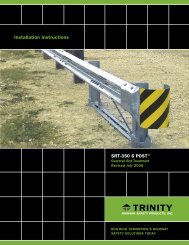
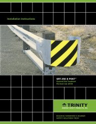
Installation Instructions - Trinity Highway Products, LLC
Installation Instructions - Trinity Highway Products, LLC
Installation Instructions - Trinity Highway Products, LLC

You also want an ePaper? Increase the reach of your titles
YUMPU automatically turns print PDFs into web optimized ePapers that Google loves.
INSTALLING THE CRT POSTS<br />
(LOCATIONS 3 THROUGH 6)<br />
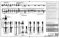
Install the wood posts (PN-3118B) at all locations where the tubes are not used (See states<br />
standards). These posts may be driven. They may also be installed by drilling holes<br />
approximately 44” (1120 mm) deep. Insert the 6’0” (1830 mm) wood post into these holes<br />
and backfill. Note that in either case, the bottom of the upper 3 1/2” (90 mm) hole in the post<br />
is approximately at finished grade.<br />
INSTALLING THE STRUT<br />
Place the angle ground strut (PN-33875G) on the embankment side of the foundation tubes.<br />
If the CAT-350 TM is installed close to the center of a median, the strut can be placed on either<br />
side. A 3/4” (19 mm) diameter x 9 1/2” (240 mm) hex hd. high strength bolt (PN-5148G) is<br />
used to attach the strut to the foundation tube, and should be installed from the embankment<br />
side. A washer (PN-3700G) is placed between the bolt head and the strut and the nut (PN-<br />
3704G) and the foundation tube.<br />
An alternate to the angle strut is the channel ground strut (PN-9852A). Place the slotted<br />
yokes of the ground strut over the foundation tubes at posts 1 and 2. A 5/8” (16 mm)<br />
diameter x 9 1/2” (240 mm) hex head bolt (PN-3497G) is used to attach the strut to the<br />
foundation tube. Note that the bolt goes through the strut, the foundation tube, and the wood<br />
post and should be installed from the embankment side. A washer (PN-3300G) is placed<br />
between the bolt head and the strut and the nut (PN-3340G) and the strut.<br />
DO NOT OVERTIGHTEN THE BOLTS AND DEFORM THE TUBES.<br />
There is no torque requirement for these bolts. They should be tightened to a snug<br />
position.<br />
INSTALLING WOOD BLOCKOUTS AND GUARDRAIL<br />
There are no rail-to-post attachments at locations 3,5 and 6. Attach the wood blocks (PN-<br />
3101B), two (2) per post, at these locations using two 5/8" X 24" (16mm X 610mm) hex bolts<br />
(PN-4640G), hex nuts (PN-3340G) and washers (PN-3300G). The washers are placed under<br />
both the nut and bolt head.<br />
Before installing any of the CAT-350 TM rail panels, make sure the downstream rail is inn<br />
place. This rail will either be the main line barrier or the tail-end section.<br />
Start with the two (2) 10-gage rail panels (PC130A) that span from post 4 to post 6. These<br />
are the slotted rails with plates welded to the backside on one end. The welded plates are<br />
placed at post 4.<br />
These rails are lapped to the outside of the rail extending beyond post 6. The rail splice at<br />
post 6 is made with eight (8) plate washers (PC-19259G) and eight 5/8" X 1-3/4" (16mm X<br />
45mm) special hex head bolts (PN-3395G) and hex nuts (PN-3350G). The word “C-A-T”<br />
6