Submersible Sewage Ejector Pump - Sump Pumps
Submersible Sewage Ejector Pump - Sump Pumps
Submersible Sewage Ejector Pump - Sump Pumps

You also want an ePaper? Increase the reach of your titles
YUMPU automatically turns print PDFs into web optimized ePapers that Google loves.
4<br />
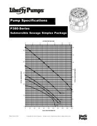
<strong>Pump</strong><br />
Servicing<br />
plug. The ohmmeter should be<br />
on R X 1 setting. Normal<br />
readings are 1.4 to 1.54 ohms<br />
for 115V, 4.5 to 4.9 for 230V.<br />
To check the ground, place the<br />
ohmmeter on R X 100k,<br />
connect one lead clip to the<br />
“ground” prong on the power<br />
cord and touch the other lead<br />
clip to each “flat” prong<br />
individually. If the reading is<br />
other than infinity (∞ on the<br />
ohmmeter scale), a leakage<br />
through stator insulation or<br />
moisture in the windings is<br />
occurring and the stator must<br />
be removed, dried out and<br />
rechecked. A reading at zero<br />
indicates a dead short and the<br />
stator will have to be replaced.<br />
6. To check to see if water has<br />
entered the motor cap, remove<br />
the pipe plug (14) at the top of<br />
the pump and drain the oil into<br />
a bucket. A milky appearance<br />
to the oil indicates that<br />
water has entered through<br />
either worn or damaged seals<br />
or O-rings and replacement<br />
is necessary.<br />
7. Remove the four hex-head<br />
screws (7) from the motor<br />
housing and lift off the motor<br />
housing (4) very carefully as a<br />
grounding wire is attached to<br />
the inside of the motor housing<br />
(4). Remove the ground screw<br />
(13) and set the motor housing<br />
(4) aside.<br />
8. To remove impeller, hold the<br />
rotor shaft assembly with<br />
screwdriver (screwdriver slot<br />
in shaft). Carefully tap impeller<br />
off shaft with a plastic or<br />
rubber hammer. Tap impeller<br />
(11) counterclockwise to<br />
remove. Loctite #277 is<br />
applied to shaft at assembly, so<br />
to remove impeller it will be<br />
necessary to break this seal.<br />
This is why the plastic or<br />
rubber hammer is used to<br />
avoid damage to the impeller.<br />
9. Insert a screwdriver under the<br />
edge of the ceramic seal (6)<br />
and lift it off.<br />
10.Remove the stationary half of<br />
the seal (6) by tapping it out<br />
lightly from the top of the seal<br />
plate and then clean the area<br />
with a cloth.<br />
11.Remove the four bolts (16)<br />
holding the motor (12) onto<br />
the seal plate (10) and tap the<br />
shaft and rotor assembly out<br />
with a plastic or rawhide<br />
hammer. The lower ball<br />
bearing will come out with the<br />
shaft and rotor assembly. If<br />
the bearing is rusted or feels<br />
rough when turned, it should<br />
be replaced as in Step 13.<br />
12.Coat the replacement seal (6)<br />
with a thin oil (dielectric,<br />
same as in motor housing)<br />
coating and use a plastic<br />
pusher to install the seal (6)<br />
into the seal plate (10). Do not<br />
use any sharp instruments that<br />
may damage the seal. Do not<br />
chip, scratch or mar the carbon<br />
face.<br />
13.If ball bearing replacement is<br />
necessary as determined in<br />
Step 11, press the bearing on<br />
the shaft, pushing only on the<br />
inner face. If a press is not<br />
available, the bearing can be<br />
tapped on using a sleeve that<br />
bears only on the inner face.<br />
Pressing on the outer face will<br />
result in flat spots on the bearing<br />
and cause early failure.<br />
14.Push the new rotor shaft and<br />
ball bearing assembly into<br />
the seal plate. (Note that the<br />
replacement rotor must be of<br />
the same manufacture as the<br />
existing stator, or vice versa.)<br />
Reassemble the stator (12) to<br />
the seal plate (10) with the four<br />
long cap screws (16). Be sure<br />
to tighten down the bolts<br />
evenly and firmly to prevent<br />
cocking of the stator. An<br />
uneven assembly can cause the<br />
rotor to rub the motor causing<br />
the motor to short.<br />
15.Press the new ceramic seal (6)<br />
in place with the rubber<br />
ring facing the impeller.<br />
This should have a thin oil<br />
(dielectric, same as in motor<br />
housing) coating.<br />
Note: Ceramic must be kept<br />
clean. Any dirt will cause<br />
seal failure.<br />
16.Start the impeller on the shaft<br />
one to two turns; then add a<br />
drop of Loctite #277 to the<br />
impeller threads and screw<br />
the impeller hand tight. The<br />
impeller will force the ceramic<br />
seal into position. The shaft<br />
should be free of dirt, grease,<br />
etc., or the Loctite will not<br />
hold as designed.<br />
Note: Loctite overrun onto the<br />
seal or bearing will result in<br />
shaft seizure.<br />
17.Remove the old seal ring (8)<br />
and stretch on new ring with<br />
O-ring lube.<br />
Do not roll the ring onto seal<br />
plate or water leakage into the<br />
motor housing will result.<br />
18.Fasten the ground wire inside<br />
the motor housing and tuck<br />
wires up into the housing to<br />
prevent rubbing on the rotor;<br />
then assemble housing (4) to<br />
volute (9) with bolts (7).<br />
19.Check for seal leaks by<br />
pressurizing the pump to 7 to 9