Submersible Sewage Ejector Pump - Sump Pumps
Submersible Sewage Ejector Pump - Sump Pumps
Submersible Sewage Ejector Pump - Sump Pumps

You also want an ePaper? Increase the reach of your titles
YUMPU automatically turns print PDFs into web optimized ePapers that Google loves.
<strong>Pump</strong> Installation and Service Manual<br />
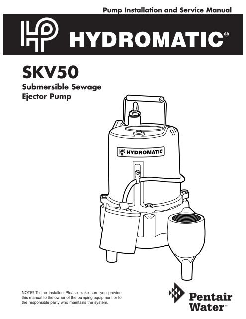
SKV50<br />
<strong>Submersible</strong> <strong>Sewage</strong><br />
<strong>Ejector</strong> <strong>Pump</strong><br />
NOTE! To the installer: Please make sure you provide<br />
this manual to the owner of the pumping equipment or to<br />
the responsible party who maintains the system.
General<br />
Information<br />
Thank you for purchasing your<br />
Hydromatic ® pump. To help<br />
ensure years of trouble-free<br />
operation, please read the<br />
following manual carefully.<br />
Before Operation:<br />
Read the following instructions<br />
carefully. Reasonable care and<br />
safe methods should be practiced.<br />
Check local codes and<br />
requirements before installation.<br />
Attention:<br />
This manual contains important<br />
information for the safe use of<br />
this product. Read this manual<br />
completely before using this<br />
product and refer to it often for<br />
continued safe product use.<br />
DO NOT THROW AWAY OR<br />
LOSE THIS MANUAL. Keep it<br />
in a safe place so that you may<br />
refer to it often.<br />
WARNING: Before handling<br />
these pumps and controls,<br />
always disconnect the power<br />
first. Do not smoke or use<br />
sparkable electrical devices or<br />
flames in a septic (gaseous) or<br />
possible septic sump.<br />
<strong>Pump</strong><br />
Warning<br />
To reduce risk of electrical shock:<br />
1. Risk of Electrical Shock:<br />
This pump has not been<br />
investigated for use in<br />
swimming pool areas.<br />
2. Risk of Electrical Shock:<br />
Connect only to a properly<br />
grounded receptacle.<br />
Septic tank to be vented<br />
in accordance with local<br />
plumbing codes.<br />
Do not smoke or use sparkable<br />
electrical devices or flame in a<br />
septic (gaseous) or possible<br />
septic sump.<br />
If a septic sump condition may<br />
exist and if entry into sump is<br />
necessary, then (1) provide<br />
proper safety precautions per<br />
OSHA requirements and (2)<br />
do not enter sump until<br />
these precautions are strictly<br />
adhered to.<br />
Do not install pump in location<br />
classified as hazardous per<br />
N.E.C., ANSI/NFPA 70 - 1999.<br />
Failure to heed above cautions<br />
could result in injury or death.<br />
<strong>Pump</strong><br />
Installation<br />
These important instructions must<br />
be followed for satisfactory<br />
performance of your pump. Before<br />
installation, check your local<br />
electrical and plumbing codes.<br />
1. Provide proper sump.<br />
Recommended minimum<br />
sump diameter is 18".<br />
2. Make sure the wide-angle<br />
float switch (excluding those<br />
automatic models equipped<br />
with a diaphragm pressure<br />
switch) hangs freely. The float<br />
should not come in contact<br />
with the side or bottom of the<br />
sump pit.<br />
3. Make sure sump is free of<br />
string, cloth, nails, gravel, etc.<br />
before installing pump.<br />
4. Do not set pump directly on<br />
the bottom of sump pit if it is<br />
not solid. Raise the pump by<br />
placing bricks or concrete<br />
blocks underneath it.<br />
5. Use steel or plastic pipe for all<br />
connecting lines between<br />
pump and sewer outlet.<br />
Note: Some city regulations<br />
do not allow installing a<br />
pump with plastic pipe. Check<br />
local regulations.<br />
6. In applications where the<br />
pump may sit idle for months<br />
at a time, it is recommended<br />
that the pump(s) be cycled<br />
every month to ensure the<br />
pumping system is working<br />
properly when needed.<br />
7. Hydromatic check valve<br />
should be installed in discharge<br />
pipe. Install check valve with<br />
arrow on valve body pointing<br />
in the direction of the flow.<br />
8. A shutoff valve should also<br />
be used.<br />
9. An audible alarm system, such<br />
as the Q Alert, for high water<br />
conditions should be installed<br />
in every pump pit for greater<br />
protection.<br />
Note: The Q Alert is for<br />
indoor use only. For outdoor<br />
applications contact your<br />
Hydromatic distributor.<br />
10.Connect to power source<br />
using 3-prong grounded AC<br />
receptacle. Do not remove<br />
ground pin from electrical<br />
plug. Do not use an extension<br />
cord or adaptor plug.<br />
11. For proper automatic operation,<br />
make sure the pump power<br />
cord is plugged into the back<br />
of the piggyback receptacle on<br />
the wide angle float switch.<br />
2
12.To ensure that the pump is<br />
properly installed, fill basin<br />
with enough water to activate<br />
pump. Allow the pump to go<br />
through several on-off cycles<br />
to assure satisfactory operation.<br />
13.Use pump partially or<br />
completely submerged for<br />
pumping waterlike liquids<br />
(temperature to 140° F).<br />
The SKV50 will pump solid<br />
materials up to 2" (spherical)<br />
in diameter.<br />
Caution: Do not pump<br />
flammable liquids, strong<br />
chemicals or salt water.<br />
Your pump warranty is void...<br />
If...power cord has been cut.<br />
If...pump has been used to<br />
pump mud, cement, tar,<br />
abrasives or chemicals.<br />
If...pump has been used for<br />
pumping of hot water<br />
(above 120° F).<br />
If...pump has been dismantled<br />
by other than authorized<br />
Hydromatic service center<br />
or distributor.<br />
<strong>Pump</strong><br />
Servicing<br />
Read the following instructions<br />
carefully before replacing any<br />
parts. Reasonable care and safe<br />
methods should be practiced.<br />
Check local codes and<br />
requirements before installation.<br />
Only competent electrician<br />
should make the installations.<br />
The following steps should be<br />
performed by an authorized<br />
Hydromatic service center<br />
or distributor.<br />
Note: Use extreme caution<br />
around electrical devices.<br />
Electrical shock may occur.<br />
1. Before removing pump from<br />
the sump, check to be sure the<br />
problem is not a blown fuse,<br />
tripped circuit breaker or a<br />
power cord not completely<br />
inserted into the receptacle.<br />
2. If the unit is being operated by<br />
an optional control switch,<br />
unplug the pump from the<br />
piggyback receptacle and plug<br />
the pump directly into the<br />
power source. If the pump<br />
starts each time it is plugged<br />
directly into the receptacle and<br />
does not start each time when<br />
plugged into the piggyback<br />
switch with the float raised or<br />
diaphragm pressed up to a start<br />
position, replace the complete<br />
switch assembly and retest<br />
with new assembly.<br />
3. If pump fails the above two<br />
steps, remove pump and<br />
switch from power source to<br />
avoid electrical shock. Then<br />
pull the pump from the sump<br />
by the handle. Sandblast, if<br />
possible, any dirt or trash<br />
from the outside of the pump<br />
before dismantling.<br />
4. If the above tests have not<br />
resolved the problem, it may<br />
be in the electrical components<br />
of the pump. Starting with the<br />
power cord, inspect for cuts or<br />
nicks in the insulation. If the<br />
cord is damaged – replace it!<br />
5. Using the ohmmeter, check<br />
the resistance of the motor<br />
windings by connecting one<br />
lead clip to each electrical<br />
“flat” prong on the power cord<br />
3
4<br />
<strong>Pump</strong><br />
Servicing<br />
plug. The ohmmeter should be<br />
on R X 1 setting. Normal<br />
readings are 1.4 to 1.54 ohms<br />
for 115V, 4.5 to 4.9 for 230V.<br />
To check the ground, place the<br />
ohmmeter on R X 100k,<br />
connect one lead clip to the<br />
“ground” prong on the power<br />
cord and touch the other lead<br />
clip to each “flat” prong<br />
individually. If the reading is<br />
other than infinity (∞ on the<br />
ohmmeter scale), a leakage<br />
through stator insulation or<br />
moisture in the windings is<br />
occurring and the stator must<br />
be removed, dried out and<br />
rechecked. A reading at zero<br />
indicates a dead short and the<br />
stator will have to be replaced.<br />
6. To check to see if water has<br />
entered the motor cap, remove<br />
the pipe plug (14) at the top of<br />
the pump and drain the oil into<br />
a bucket. A milky appearance<br />
to the oil indicates that<br />
water has entered through<br />
either worn or damaged seals<br />
or O-rings and replacement<br />
is necessary.<br />
7. Remove the four hex-head<br />
screws (7) from the motor<br />
housing and lift off the motor<br />
housing (4) very carefully as a<br />
grounding wire is attached to<br />
the inside of the motor housing<br />
(4). Remove the ground screw<br />
(13) and set the motor housing<br />
(4) aside.<br />
8. To remove impeller, hold the<br />
rotor shaft assembly with<br />
screwdriver (screwdriver slot<br />
in shaft). Carefully tap impeller<br />
off shaft with a plastic or<br />
rubber hammer. Tap impeller<br />
(11) counterclockwise to<br />
remove. Loctite #277 is<br />
applied to shaft at assembly, so<br />
to remove impeller it will be<br />
necessary to break this seal.<br />
This is why the plastic or<br />
rubber hammer is used to<br />
avoid damage to the impeller.<br />
9. Insert a screwdriver under the<br />
edge of the ceramic seal (6)<br />
and lift it off.<br />
10.Remove the stationary half of<br />
the seal (6) by tapping it out<br />
lightly from the top of the seal<br />
plate and then clean the area<br />
with a cloth.<br />
11.Remove the four bolts (16)<br />
holding the motor (12) onto<br />
the seal plate (10) and tap the<br />
shaft and rotor assembly out<br />
with a plastic or rawhide<br />
hammer. The lower ball<br />
bearing will come out with the<br />
shaft and rotor assembly. If<br />
the bearing is rusted or feels<br />
rough when turned, it should<br />
be replaced as in Step 13.<br />
12.Coat the replacement seal (6)<br />
with a thin oil (dielectric,<br />
same as in motor housing)<br />
coating and use a plastic<br />
pusher to install the seal (6)<br />
into the seal plate (10). Do not<br />
use any sharp instruments that<br />
may damage the seal. Do not<br />
chip, scratch or mar the carbon<br />
face.<br />
13.If ball bearing replacement is<br />
necessary as determined in<br />
Step 11, press the bearing on<br />
the shaft, pushing only on the<br />
inner face. If a press is not<br />
available, the bearing can be<br />
tapped on using a sleeve that<br />
bears only on the inner face.<br />
Pressing on the outer face will<br />
result in flat spots on the bearing<br />
and cause early failure.<br />
14.Push the new rotor shaft and<br />
ball bearing assembly into<br />
the seal plate. (Note that the<br />
replacement rotor must be of<br />
the same manufacture as the<br />
existing stator, or vice versa.)<br />
Reassemble the stator (12) to<br />
the seal plate (10) with the four<br />
long cap screws (16). Be sure<br />
to tighten down the bolts<br />
evenly and firmly to prevent<br />
cocking of the stator. An<br />
uneven assembly can cause the<br />
rotor to rub the motor causing<br />
the motor to short.<br />
15.Press the new ceramic seal (6)<br />
in place with the rubber<br />
ring facing the impeller.<br />
This should have a thin oil<br />
(dielectric, same as in motor<br />
housing) coating.<br />
Note: Ceramic must be kept<br />
clean. Any dirt will cause<br />
seal failure.<br />
16.Start the impeller on the shaft<br />
one to two turns; then add a<br />
drop of Loctite #277 to the<br />
impeller threads and screw<br />
the impeller hand tight. The<br />
impeller will force the ceramic<br />
seal into position. The shaft<br />
should be free of dirt, grease,<br />
etc., or the Loctite will not<br />
hold as designed.<br />
Note: Loctite overrun onto the<br />
seal or bearing will result in<br />
shaft seizure.<br />
17.Remove the old seal ring (8)<br />
and stretch on new ring with<br />
O-ring lube.<br />
Do not roll the ring onto seal<br />
plate or water leakage into the<br />
motor housing will result.<br />
18.Fasten the ground wire inside<br />
the motor housing and tuck<br />
wires up into the housing to<br />
prevent rubbing on the rotor;<br />
then assemble housing (4) to<br />
volute (9) with bolts (7).<br />
19.Check for seal leaks by<br />
pressurizing the pump to 7 to 9
pounds of air pressure. Air<br />
bubbles should appear at first,<br />
then stop. If air bubbles<br />
continue, then recheck seals.<br />
20.Fill the motor cap with<br />
high-grade transformer oil<br />
such as Sohio (6) Factopure<br />
SE40 Oil (or equivalent) to<br />
at least 1⁄4" over motor<br />
windings top plate, or to the<br />
top of the stator.<br />
Do not fill the motor housing<br />
completely. Allow air space<br />
for expansion.<br />
Replace oil pipe plug (14).<br />
Recheck with ohmmeter<br />
before applying power.<br />
21.Plug the power cord into a<br />
grounded outlet and check<br />
pump running. Motor should<br />
run smoothly and be free<br />
of vibration.<br />
2. Water level in sump may be<br />
too low to activate automatic<br />
switch. See installation for<br />
proper on/off levels.<br />
3. <strong>Pump</strong> and/or switch cord plug<br />
may not be making contact<br />
in receptacle.<br />
4. If pump is using the series<br />
(piggyback) cord plug, the two<br />
plugs may not be plugged<br />
together tightly.<br />
5. Float may be stuck. Be sure<br />
float operates freely in basin.<br />
6. If the unit is being operated by<br />
the optional float control<br />
switch, unplug the pump from<br />
the piggyback receptacle and<br />
plug the pump directly into<br />
the power source. If the<br />
pump starts each time it is<br />
plugged directly into the<br />
receptacle and does not start<br />
each time when plugged into<br />
the piggyback switch with<br />
the float raised up to a start<br />
position, replace the complete<br />
piggyback switch assembly<br />
and retest with new assembly.<br />
7. If all symptoms check OK,<br />
motor winding may be open;<br />
take to authorized service<br />
center for check.<br />
<strong>Pump</strong> runs but does not<br />
deliver water.<br />
1. Check valve may be installed<br />
backward. Arrow on valve<br />
points in direction of flow.<br />
2. Discharge shutoff valve, if<br />
used, may be closed.<br />
3. <strong>Pump</strong> may be air locked. Start<br />
and stop several times by<br />
plugging and unplugging cord.<br />
<strong>Pump</strong><br />
Troubleshooting<br />
1 14<br />
3 2<br />
Servicing should be performed<br />
only by an authorized Hydromatic<br />
service center.<br />
Warning: Always disconnect the<br />
pump from power source<br />
before handling or making any<br />
adjustments. Always wear<br />
rubber boots when there is<br />
water on the floor and you must<br />
unplug the pump or make<br />
any adjustments.<br />
7<br />
15<br />
19<br />
20<br />
18<br />
17<br />
4<br />
12<br />
21<br />
8<br />
Note: Automatic thermal<br />
overload protects the sealed-inoil<br />
motor. Running dry may<br />
overheat the motor and activate<br />
the overload protector until the<br />
unit cools.<br />
6<br />
9<br />
<strong>Pump</strong> does not run or just hums.<br />
1. Line circuit breaker may be off,<br />
or fuse may be blown or loose.<br />
11<br />
10<br />
5
<strong>Pump</strong><br />
Troubleshooting<br />
Check vent hole in pump case<br />
for plugging.<br />
Hydromatic pumps have a<br />
small air vent hole in the<br />
impeller cavity to let out<br />
trapped air. If this hole<br />
becomes plugged, pump may<br />
air lock. To break the air lock,<br />
use a small screwdriver to<br />
clear hole in the impeller<br />
cavity.<br />
As a secondary precaution in<br />
installations of this type —<br />
1/16" hole should be drilled in<br />
the discharge pipe below the<br />
check valve. The check valve<br />
should be 12 to 18 inches<br />
above pump discharge. Do not<br />
put check valve directly into<br />
pump discharge opening.<br />
NOTE: In sumps where the<br />
pump is operating daily, air<br />
locking rarely occurs.<br />
4. <strong>Pump</strong> head may be too high.<br />
<strong>Pump</strong> cannot deliver water<br />
over 24' vertical lift.<br />
Horizontal distance does not<br />
affect pumping, except for<br />
friction loss through the pipe.<br />
5. Inlet in pump base may be<br />
clogged. Remove pump and<br />
clean out openings.<br />
6. Impeller or volute openings<br />
may be plugged or partially<br />
plugged. Remove pump and<br />
clean out.<br />
<strong>Pump</strong> runs and pumps out<br />
sump but does not stop.<br />
1. Float is stuck in up position.<br />
Be sure float is not hung up<br />
and operates freely in basin.<br />
2. Switch contacts may be stuck;<br />
replace switch.<br />
<strong>Pump</strong> runs but delivers only<br />
small amount of water.<br />
1. <strong>Pump</strong> may be air locked. Start<br />
and stop several times by<br />
plugging and unplugging cord.<br />
Check vent hole in pump case<br />
for plugging.<br />
2. <strong>Pump</strong> head may be too<br />
high. <strong>Pump</strong> cannot deliver<br />
water over 24' vertical lift.<br />
Horizontal distance does<br />
not affect pumping, except<br />
loss due to friction through<br />
discharge pipe.<br />
3. Inlet in pump base may be<br />
clogged. Remove pump and<br />
clean out openings.<br />
4. Impeller or volute openings<br />
may be plugged or partially<br />
plugged. Remove pump and<br />
clean out.<br />
5. <strong>Pump</strong> impeller may be partially<br />
clogged causing motor to<br />
run slow, resulting in motor<br />
overload. Clear impeller.<br />
Fuse blows or circuit breaker<br />
trips when pump starts.<br />
1. Inlet in pump base may be<br />
clogged. Remove pump and<br />
clean out openings.<br />
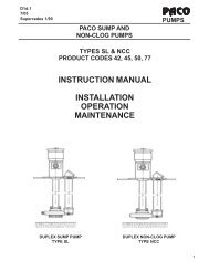
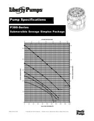
HEAD-METERS<br />
12<br />
9<br />
6<br />
3<br />
HEAD-FEET<br />
40<br />
30<br />
20<br />
10<br />
2. Impeller or volute openings<br />
may be plugged or partially<br />
plugged. Remove pump and<br />
clean out.<br />
3. <strong>Pump</strong> impeller may be partially<br />
clogged causing motor to<br />
run slow, resulting in motor<br />
overload. Clear impeller.<br />
4. Fuse size or circuit breaker is<br />
too small.<br />
5. Defective motor stator: return<br />
to authorized Hydromatic<br />
service center for verification.<br />
Motor runs for short time<br />
then stops. Then after short<br />
period starts again. Indicates<br />
tripping overload caused by<br />
symptom shown.<br />
1. Inlet in pump base may be<br />
clogged. Remove pump and<br />
clean out openings.<br />
2. Impeller or volute openings<br />
may be plugged or partially<br />
plugged. Remove pump and<br />
clean out.<br />
3. <strong>Pump</strong> impeller may be partially<br />
clogged causing motor to<br />
run slow, resulting in motor<br />
overload. Clear impeller.<br />
4. Defective motor stator: return<br />
to authorized Hydromatic<br />
service center.<br />
SKV50 PERFORMANCE CURVE<br />
1/2 HP<br />
0 0<br />
Capacity-U.S. G.P.M. 0 30 60 90 120 150 180<br />
Liters/Second 0 2 4 6 8 10<br />
6
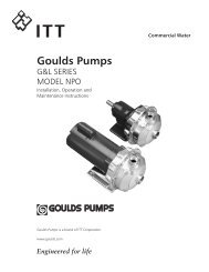
SKV50<br />
Parts List<br />
1 14<br />
3 2<br />
15<br />
19<br />
20<br />
18<br />
17<br />
4<br />
12<br />
7<br />
21<br />
8<br />
9<br />
6<br />
Refer to an authorized<br />
Hydromatic service<br />
center to order parts.<br />
11<br />
10<br />
Ref. No. Part No. Description Qty.<br />
1 60-000-5 Handle 1<br />
2 4580-001-1 Drive Screw 2<br />
3 13425-069-1 Nameplate 1<br />
4 56-036-2 Motor Housing 1<br />
6 14525A010 Seal Assy. 1<br />
7 19100A012 Capscrew 4<br />
8 77-003-1 Seal Ring 1<br />
9 6818-100-2 Volute 1<br />
10 6846-003-1 Seal Plate 1<br />
11 8498-006-1 Impeller 1<br />
12 13559-000-1 Stator & Shell 115V Motor 1<br />
12 13593-000-1 Stator & Shell 230V Motor 1<br />
14 14981-001-1 Pipe Plug 1<br />
15 14623-010-1 Cord Assy. *16-3, 10', 115V 1<br />
Ref. No. Part No. Description Qty.<br />
15 14623-020-1 Cord Assy. *16-3, 20', 115V 1<br />
15 14623-210-1 Cord Assy. *16-3, 10', 230V 1<br />
15 14623-220-1 Cord Assy. *16-3, 20', 230V 1<br />
17 6000-053-1 Wire with Terminal 1<br />
18 6000-061-1 Wire with Terminals 2<br />
19 75-005-1 Cord Nut 1<br />
20 139-014-1 Cord Grommet 1<br />
21 13666-000-1 Ground Strap 1<br />
FOR AUTOMATIC OPERATION<br />
Not 13967-011-5 Piggyback Switch, 115V-10' Cord 1<br />
Shown 13967-021-5 Piggyback Switch, 115V-20' Cord 1<br />
14974-008-5 D-Switch, 115V-10' Cord 1<br />
7
LIMITED WARRANTY<br />
HYDROMATIC warrants to the original consumer purchaser (“Purchaser” or “You”) of HYDROMATIC <strong>Sump</strong><br />
<strong>Pump</strong>s, Effluent <strong>Pump</strong>s, <strong>Sewage</strong> <strong>Pump</strong>s (other than 2-1/2"), and Package Systems, that they will be free from<br />
defects in material and workmanship for the Warranty Period of 36 months from date of manufacture.<br />
Our warranty will not apply to any product that, in our sole judgement, has been subject to negligence,<br />
misapplication, improper installation, or improper maintenance. Without limiting the foregoing, operating a<br />
three phase motor with single phase power through a phase converter will void the warranty. Note also that<br />
three phase motors must be protected by three-leg, ambient compensated, extra-quick trip overload relays of<br />
the recommended size or the warranty is void.<br />
Your only remedy, and HYDROMATIC’s only duty, is that HYDROMATIC repair or replace defective products<br />
(at HYDROMATIC’s choice). You must pay all labor and shipping charges associated with this warranty and<br />
must request warranty service through the installing dealer as soon as a problem is discovered. No request<br />
for service will be accepted if received after the Warranty Period has expired. This warranty is not transferable.<br />
EXCEPTIONS: Hydromatic Special Application <strong>Pump</strong>s, Battery Back-Up <strong>Sump</strong> <strong>Pump</strong>s, Filtered Effluent<br />
<strong>Pump</strong>s, Grinder <strong>Pump</strong>s, and 2-1/2" <strong>Sewage</strong> <strong>Pump</strong>s are warranted for a period of 12 months from date of<br />
purchase or 18 months from date of manufacture, whichever comes first.<br />
HYDROMATIC SHALL NOT BE LIABLE FOR ANY CONSEQUENTIAL, INCIDENTAL, OR CONTINGENT<br />
DAMAGES WHATSOEVER.<br />
THE FOREGOING WARRANTIES ARE EXCLUSIVE AND IN LIEU OF ALL OTHER EXPRESS AND<br />
IMPLIED WARRANTIES, INCLUDING BUT NOT LIMITED TO THE IMPLIED WARRANTIES OF<br />
MERCHANTABILITY AND FITNESS FOR A PARTICULAR PURPOSE. THE FOREGOING WARRANTIES<br />
SHALL NOT EXTEND BEYOND THE DURATION EXPRESSLY PROVIDED HEREIN.<br />
Some states do not allow the exclusion or limitation of incidental or consequential damages or limitations on<br />
the duration of an implied warranty, so the above limitations or exclusions may not apply to You. This warranty<br />
gives You specific legal rights and You may also have other rights which vary from state to state.<br />
This warranty supersedes and replaces all previous warranty publications.<br />
HYDROMATIC<br />
740 East 9th Street, Ashland, OH 44805<br />
Phone: 888-957-8677 • Fax: 888-840-7867 • Web Site: http://www.hydromatic.com<br />
– Your Authorized Local Distributor –<br />
USA<br />
740 East 9th Street, Ashland, Ohio 44805<br />
Tel: 888-957-8677 Fax: 888-840-7867<br />
© 2007 Hydromatic ® Ashland, Ohio. All Rights Reserved.<br />
www.hydromatic.com<br />
CANADA<br />
269 Trillium Drive, Kitchener, Ontario, Canada N2G 4W5<br />
Tel: 519-896-2163 Fax: 519-896-6337<br />
Part # 5625-364-1<br />
Item # W-03-364 Rev. 9/22/09