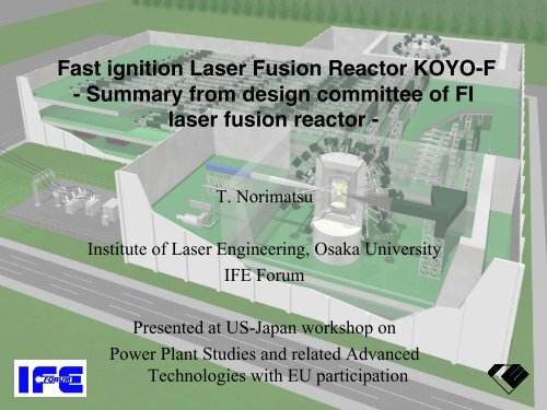
Fast ignition Laser Fusion Reactor KOYO-F - Summary from design ...
Fast ignition Laser Fusion Reactor KOYO-F - Summary from design ...
Fast ignition Laser Fusion Reactor KOYO-F - Summary from design ...

You also want an ePaper? Increase the reach of your titles
YUMPU automatically turns print PDFs into web optimized ePapers that Google loves.
<strong>Fast</strong> <strong>ignition</strong> <strong>Laser</strong> <strong>Fusion</strong> <strong>Reactor</strong> <strong>KOYO</strong>-F<br />
- <strong>Summary</strong> <strong>from</strong> <strong>design</strong> committee of FI<br />
laser fusion reactor -<br />
ILE, Osaka<br />
T. Norimatsu<br />
Institute of <strong>Laser</strong> Engineering, Osaka University<br />
IFE Forum<br />
Presented at US-Japan workshop on<br />
Power Plant Studies and related Advanced<br />
Technologies with EU participation
After the Roadmap committee, we organized a<br />
conceptual <strong>design</strong> committee to make the issue clear.<br />
In total, 34 working group meetings were held <strong>from</strong><br />
March 2004 to Sep. 2005.<br />
• Chair; A. Tomabechi<br />
• Co-chair; Y. Kozaki (IFE, Forum)<br />
T. Norimatsu (ILE, Osaka)<br />
ILE, Osaka<br />
Core plasma Working Group<br />
<strong>Laser</strong> Working Group<br />
Target Working Group<br />
Plant system Working Group<br />
H. Azechi (ILE, Osaka)<br />
N. Miyanaga (ILE, Osaka)<br />
T. Norimatsu (ILE, Osaka)<br />
Y. Kozaki (IFE, Forum)<br />
K. Mima (ILE, Osaka)<br />
K. Ueda (U. Elec.Com.)<br />
A. Iwamoto (NIFS)<br />
Y. Ueda (Osaka U.)<br />
Y. Nakao (Kyushu U.)<br />
Y. Owadano (Nat. I. Adv. Ind. Sci.)<br />
T. Endo (Hiroshima U.)<br />
K. Okano (Cent. Res. Ins.)<br />
H. Sakagami (Hyogo U.)<br />
M. Nakatsuka (ILE, Osaka.)<br />
H. Yoshida (Gifu U.)<br />
T. Kunugi (Kyoto U.)<br />
H. Shiraga (ILE, Osaka)<br />
K. Yoshida (Osaka)<br />
M. Nishikawa (Kyushu U.)<br />
Y. Sakawa (Nagoya U.)<br />
R. Kodama (ILE, Osaka)<br />
H. Nakano (Kinki U.)<br />
S. Konishi (Kyoto U.)<br />
H. Nakano (Kinki U.)<br />
H. Nagatomo (ILE, Osaka)<br />
H. Kubomura (Hamamatsu Co.)<br />
A. Sagara (NIFS)<br />
T. Jhozaki (ILE, Osaka)<br />
K. Kawashima (Hamamatsu Co)<br />
Y. Soman (Mitsubishi Co)<br />
Y. Suzuki (<strong>Laser</strong> Front Tech.)<br />
M. Nishikawa (Kyushu U.)<br />
T. Jitsuno (ILE, Osaka)<br />
Hayashi<br />
(JAERI)<br />
H. Fujita (ILE, Osaka)<br />
H. Furukawa (ILE, Osaka)<br />
J. Kawanaka (ILE, Osaka)<br />
M. Nakai (ILE, Osaka)<br />
T. Kanabe (Fukui U.)<br />
T. Kanabe (Fukui U.)<br />
Y. Fujimoto ( ILE, Osaka)<br />
Y. Fujimoto ( ILE, Osaka)<br />
K. Tsubakimoto (ILE, Osaka)<br />
K. Tsubakimoto (ILE, Osaka)<br />
Y. Furukawa (ILE, Osaka)<br />
Y. Furukawa (ILE, Osaka)<br />
The committee is supported by IFE Forum and ILE, Osaka Univ.
Outline<br />
• Introduction<br />
– <strong>Fast</strong> <strong>ignition</strong><br />
– Gain estimation and the emission<br />
• Chamber and plant system<br />
• <strong>Laser</strong> system<br />
• Fueling system<br />
ILE, Osaka
<strong>Fast</strong> <strong>ignition</strong> is attractive , because the gain<br />
is high with a small laser<br />
Processes for compression and <strong>ignition</strong> are separated.<br />
ILE, Osaka<br />
<strong>Laser</strong> irradiation Compression Ignition Burn<br />
Central <strong>ignition</strong><br />
100<br />
<strong>Fast</strong> Ignition<br />
Required gain for reactor<br />
<strong>KOYO</strong><br />
(Osaka <strong>design</strong>)<br />
<strong>Fusion</strong> Gain<br />
<strong>Fast</strong> <strong>ignition</strong><br />
10<br />
US-NIF<br />
r h<br />
ρ h < ρ c /4<br />
PW laser<br />
Central Ignition<br />
r c<br />
<strong>Fast</strong> heating of compressed fuel<br />
to create a hot spot at its edge<br />
1<br />
0.1 1<br />
<strong>Laser</strong> Energy<br />
(MJ)<br />
10<br />
<strong>Fast</strong> heating needs petawatt laser.<br />
r h < r c /4<br />
Critical issue is relativistic dense<br />
ρ h ~ ρ c electron dynamics.<br />
r c
5<br />
FIREX-1 project has been started to<br />
demonstrate Ti = 5 keV.<br />
ILE, Osaka<br />
Gekko XII laser<br />
LFEX laser
600 times liquid density and 1keV<br />
heating have been demonstrated<br />
ILE, Osaka<br />
Power required<br />
点 火 に 必 要 と<br />
for <strong>ignition</strong><br />
予 測 されるパワー<br />
0.8 keV<br />
DD Neutron Yield<br />
10 6<br />
0.4 keV<br />
10 4<br />
Heating<br />
efficiency 加 熱 効 率 30% 30%<br />
10 8 Heating 加 熱 効 率<br />
efficiency 15% 15%<br />
0.1 1<br />
Heating <strong>Laser</strong> Power (PW)<br />
H. Azechi, LPB 91<br />
R. Kodama, Nature 01&02
Two-D simulation checked by implosion experiments at<br />
Rochester 実 験 によりベンチマークされた2 Univ. indicated 次 元 シミュレーションにより,コーンターゲットに<br />
that high density compression of<br />
おいても 固 体 密 度 の2000 倍 以 上 の 圧 縮 が 予 測 されている.<br />
reactor-scale, cone target is possible.<br />
ILE, 阪 大 ーGA GA, 共 Rochester<br />
同 研 究<br />
collaboration<br />
ILE, Osaka<br />
S. Hatchet LLNL, APS/DPP '01<br />
One of key requirements to start<br />
FIREX-II is satisfied.<br />
したがってFIREXを 実 施 するキーディシジョン<br />
を 下 すことができる 段 階 に 入 ったと 思 われる.
Although dynamics of cone-guided implosion is quite different <strong>from</strong><br />
conventional spherical one, high ρR for <strong>ignition</strong> can be achieved<br />
ILE Osaka<br />
•existence of the cone causes<br />
non-symmetric<br />
slip boundary<br />
ablated plasma<br />
ILE, Osaka<br />
•implosion velocity<br />
•shock hits the surface<br />
of the cone<br />
•timing of maximum density<br />
•hot spot
High gain will be achieved by<br />
increasing the laser energy at the<br />
same intensity.<br />
FIREX-I Q~0.2 0.1<br />
Heating pulse<br />
ILE, Osaka<br />
FIREX-II Q~8<br />
0.35-PW<br />
Electron Beam<br />
Demo Q~150<br />
By increaseing the core<br />
size, high gain will be<br />
achieved.<br />
Johzaki 2003
<strong>Fast</strong> Ignition Gain Performance<br />
ρ = 300g/cc, α = 2 and 3<br />
Energy coupling; η imp = 5% for implosion & η heat = 30% for core heating<br />
ILE, Osaka<br />
In high gain region, target gain considerably decreases with increasing adiabat α.<br />
Wet wall<br />
reactor<br />
Gain, Q<br />
100<br />
10<br />
1<br />
FIREX-1<br />
α = 2<br />
Self-Ignition<br />
High-Gain<br />
FIREX-2<br />
Dry wall<br />
reactor<br />
α = 3<br />
Driven-Ignition<br />
0.1<br />
10 100 1000<br />
E Ltot [kJ]
Outline<br />
• Introduction<br />
• Chamber and plant system<br />
– Chamber structure<br />
– Pumping<br />
– Protection of final optics<br />
• <strong>Laser</strong> system<br />
• Fueling system<br />
ILE, Osaka
<strong>KOYO</strong>-F with 32 beams for<br />
compression and one heating beam<br />
• Vertically off-set<br />
irradiation<br />
ILE, Osaka<br />
• Cascade surface flow<br />
with mixing channel<br />
• SiC panels coated with<br />
wetable metal<br />
• Tilted first panels to<br />
make no stagnation<br />
point of ablated vapor<br />
• Compact rotary<br />
shutters with 3<br />
synchronized disks
The surface flow is mixed with inner<br />
cold flow step by step to reduce the<br />
surface temperature.<br />
ILE, Osaka<br />
LiPb flow<br />
Steel vessel
Thermal flow of <strong>KOYO</strong>-F<br />
( One module)<br />
ILE, Osaka<br />
300 MWe<br />
Water<br />
cycle<br />
300 ℃<br />
LiPb cycle<br />
300 ℃<br />
50MW<br />
Chamber<br />
70MW<br />
210MW<br />
Turbin<br />
SG<br />
904MW<br />
F2+F3 (80cm)<br />
12.84 ton/s<br />
Average flow 7.8 cm/s<br />
70MW<br />
F1 (20cm)<br />
8.56 ton/s<br />
Average flow 24.3 cm/s<br />
η ther-elec =30%<br />
500 ℃<br />
Flow rate 21.4 ton/s<br />
240MW<br />
500 ℃<br />
80MW<br />
80MW<br />
200MJ<br />
/shot<br />
x 4Hz
Specification of <strong>KOYO</strong>-F<br />
ILE, Osaka<br />
Net output 1200 MWe (300 MWe × 4 )<br />
<strong>Laser</strong> energy 1.1 MJ<br />
Target gain 165<br />
<strong>Fusion</strong> pulse out put 200 MJ<br />
<strong>Reactor</strong> pulse rep-rate 4 Hz<br />
Blanket energy multiplication 1.2<br />
<strong>Reactor</strong> thermal output 916 MWth<br />
Total plant thermal output 3664 MWth (916 MWth × 4 )<br />
Thermal electric efficiency 41.5 %(LiPb Temperature ~500 C)<br />
Total electric output 1519 MWe<br />
laser efficiency 11.4 % (implosion) , 4.2 % (heating), total 8%<br />
<strong>Laser</strong> pulse rep-rate 16 Hz<br />
<strong>Laser</strong> recirculating power 240 MWe(1.2 MJ × 16 Hz / 0.08)<br />
Yb-YAG laser operating 150K or 220K)<br />
Total plant efficiency 32.8 %( 1200 MWe/ 3664 MWth)
Estimation of Output Energy Structure<br />
200MJ output (~1.2MJ driver; 1.14MJ imp +<br />
71.5kJ heat) Case<br />
Core heating<br />
region<br />
400µm<br />
Z<br />
Simulation<br />
box<br />
89µm<br />
4<br />
1<br />
3<br />
r<br />
2<br />
ILE, Osaka<br />
(a) Output Power and Energy Spectrum of of<br />
α-particles leaking <strong>from</strong> each boundary<br />
( 1 ~ 4 )<br />
(b) Output Power of Radiation leaking <strong>from</strong><br />
each boundary ( 1 ~ 4 )<br />
(c) Output Power of Debris (thermal +<br />
Kinetic) leaking <strong>from</strong> each boundary ( 1 ~<br />
4 )<br />
Output Power [W]<br />
1E20<br />
1E19<br />
1E18<br />
1E17<br />
1E16<br />
<strong>Fusion</strong><br />
Neutron<br />
Alpha<br />
Radiation<br />
Debris<br />
200µm<br />
1E15<br />
0 50 100 150 200 250 300<br />
Time [ps]
<strong>Summary</strong> of Burn Properties<br />
Input and output energies [MJ] for ~ 200MJ output<br />
case<br />
ILE, Osaka<br />
Driver Energy ※1 1.12<br />
Implosion 1.14<br />
Heating 0.0715<br />
Energy [MJ] Heating side (1) Opposite side (4)<br />
<strong>Fusion</strong> [MJ] 200<br />
Carried out by<br />
Neutron ※2 160 (80.0%) 12.7 MJ/str 12.7 MJ/str<br />
Alpha ※3 11.8 ( 5.9%) 1.31 MJ/str 0.67 MJ/str<br />
Debris ※4 19.4 ( 9.7%) 2.26 MJ/str 1.34 MJ/str<br />
Radiation 1.85 ( 0.9%) 0.12 MJ/str 0.15 MJ/str<br />
error 6.9 ( 3.4%)<br />
Gain 165<br />
Z<br />
511µm<br />
4<br />
Simulation<br />
box<br />
117µm<br />
1<br />
3<br />
r<br />
2<br />
※1 The energy coupling efficiencies of 5% and 30% were assumed for implosion and<br />
core heating, respectively.<br />
※2 Neutrons were assumed to be freely and isotropically escaped <strong>from</strong> the core.<br />
※3 Alpha particle: Leakage/Source = 29.8% (70.2% is deposited inside the core.)<br />
※4 Constitution (energy D:35.5%, T:49.9%, α:14.3% / Number D:43.6%, T:44.5%, α:11.5%)<br />
258µm
The speed of ablated vapor 500 m/s at<br />
higher density region and 4000 m/s at the<br />
front.<br />
(This work is on the way. Depends on the model for stoping range.)<br />
ILE, Osaka<br />
Intensity (W/cm 2 )<br />
10 9 15<br />
R = 3 m<br />
10 8<br />
10 7<br />
Ablation Depth<br />
10<br />
10 6<br />
10 5<br />
tritium<br />
10 4<br />
5<br />
alfa<br />
10 3<br />
10 2<br />
0 500 1000 1500<br />
0<br />
2000<br />
Time (ns)<br />
Ablation Depth µ (m)<br />
- 3<br />
)<br />
10 23<br />
10 22<br />
Case 1 , R = 3 m<br />
Time = 2000 ns<br />
10 21<br />
Velocity<br />
V=500m/s<br />
10 20<br />
10 19<br />
Number Density<br />
10 18<br />
0<br />
-2 -1 0 1 2 3 4 5 6<br />
x (mm)<br />
5000<br />
4000<br />
3000<br />
Velocity (m/s)<br />
2000<br />
1000<br />
P 8
Total mass of ablated materials was 6.2<br />
kg/shot including oblique-incidence effect.<br />
ILE, Osaka<br />
6<br />
z(m)<br />
θ<br />
3<br />
4<br />
r(m)
Lot of 0.1 µm radius clusters are<br />
formed after adiabatic expansion.<br />
(Luk’yanchuk, Zeldovich-Raizer Model)<br />
ILE, Osaka
Future work: Hydrodynamic simulation including<br />
phase change is necessary to discuss the<br />
formation of aerosol.<br />
ILE, Osaka<br />
Jet formation<br />
t=2ms<br />
t=10ms<br />
70m/s<br />
140m/s<br />
250m/s<br />
Size of evaporated<br />
vapor in flight<br />
RT instabilities would form<br />
larger particles. -->
QuickTimeý Dz<br />
TIFFÅiLZWÅj êLí£ÉvÉçÉOÉâÉÄ<br />
ÇDZÇÃÉsÉNÉ`ÉÉǾå©ÇÈÇ…ÇÕïKóvÇ-ÇÅB<br />
Four Pb diffusion pumps will be used<br />
to keep the chamber less than 5 Pa<br />
Dry scroll pump unit<br />
~ 0.4 x 0.3 x 0.4m each<br />
~ 38 kg, 600 L/min<br />
1 unit = 10 pumps<br />
(Total size:~ 1x1x1m<br />
for a unit)<br />
Vacuum port<br />
Configuration of a vacuum pump set<br />
Pb diffusion pump<br />
0.9 m<br />
Φ 0.45m<br />
Pb vapor<br />
9.4m 3 /s<br />
for air<br />
Inside:<br />
1073K<br />
Pb liquid:673K<br />
Alumina vessel + metal jacket<br />
(Total size:~ Φ1x1m)<br />
ILE, Osaka<br />
Pb diffusion<br />
pump<br />
LiPb 上 部 ブランケット<br />
300 ℃<br />
A A’<br />
6m<br />
5m<br />
Φ 0.55m<br />
Dry scroll<br />
pump unit<br />
A<br />
10000.00<br />
A'<br />
φ6000.00<br />
To Tritium<br />
process system<br />
A-A' 断 面 図<br />
LiPb 液 体 壁 チェンバ- 概 念 図 1/100 単 位 mm<br />
<strong>Fusion</strong> output 200 MJ / pulse, 800 MW,Pulse rep-rate s 4 Hz<br />
Chamber inner radius 3.0 m, upper wall distance <strong>from</strong> burning center 10.0 m<br />
Pulse heat load max. 32 J / cm2 , upper wall 2.9 J / cm2<br />
average heat load max. 128 W / cm2 , upper wall 11.5 W / cm2<br />
Neutron wall load max. 5.6 MW / m2, upper wall 0.5 MW / m2<br />
Pb diffusion pump<br />
Dry scroll pump unit<br />
(1 x 1 x 1m)
A set of 3 rotary shutters and buffer<br />
gas will be used to protect the final<br />
optics <strong>from</strong> the bluster wave.<br />
ILE, Osaka<br />
2500<br />
32 Hz 16 Hz 4Hz<br />
Temperatrue<br />
of inner surface (K)<br />
2000<br />
1500<br />
1000<br />
Wall surface<br />
Gas temperature<br />
(Local peak)<br />
Hole on 3rd disk<br />
Hole on 2nd disk<br />
Hole on 1st disk<br />
Vapor<br />
500<br />
Blaster<br />
waves<br />
1st shutter<br />
32rps<br />
2nd shutter<br />
16rps<br />
3rd shutter<br />
4rps<br />
Open<br />
Open<br />
Open<br />
v=3,000m/s<br />
@20,000K<br />
1st bluster wave <strong>from</strong> the wall<br />
v=150 m/s<br />
10µ s 100µ s 1ms<br />
10ms 100ms<br />
1s<br />
Charged particlies <strong>from</strong> plasma 1 - 2 μ s<br />
alpha 0.2 - 0.4 μ s<br />
X-rays 10 ns<br />
Miss fired target<br />
Target injection<br />
2nd shot<br />
3rd shot<br />
4th shot
Vapor coming into the beam duct can be<br />
stopped with 0.1Torr D 2 buffer gas.<br />
ILE, Osaka<br />
0.5m<br />
100m/s<br />
• The speed of vapor is decelerated <strong>from</strong> 100 m/s to 30 m/s before the plume<br />
breaks due to RT instabilities.<br />
• Mass of Pb vapor coming into the beam duct is10mg/shot, that means 1<br />
ton/year! Periodic cleaning in necessary.
Outline<br />
• Introduction<br />
– <strong>Fast</strong> <strong>ignition</strong><br />
– Core plasma<br />
• Chamber and plant<br />
• <strong>Laser</strong> system<br />
– Cooled, ceramic Yb:YAG<br />
– Beam distributor<br />
• Fueling system<br />
ILE, Osaka
Key technologies of laser for FI fusion plant<br />
ILE, Osaka<br />
Foot pulse to form pre-plasma<br />
・32 beams<br />
Controlled focus pattern<br />
・2 ω<br />
・wide band<br />
・coherent during amplification<br />
in-coherent at focus point<br />
Main pulse for compression<br />
・32 beams<br />
Controlled focus pattern<br />
・3ω<br />
・ wide band<br />
・ coherent during amplification<br />
low-coherent at focus point<br />
<strong>Laser</strong>s<br />
16Hz<br />
Distributor<br />
Heating pulse<br />
・1beam<br />
coherently bundled<br />
・ω<br />
・wide band<br />
OPCPA<br />
・Pulse compression<br />
Grating<br />
Common technologies for compression and heating lasers<br />
・main amplifier<br />
laser material, LD<br />
Structure, optical shutter<br />
・beam switching<br />
<strong>Laser</strong>:16Hz, reactor:4Hz<br />
・Optics with multi-coating
Basic specification of lasers for reactor<br />
ILE, Osaka<br />
Wave length<br />
Energy/pulse<br />
Pulth width<br />
Pulse shape<br />
Beam number<br />
F number<br />
Uniformity<br />
Spot size<br />
Rep-rate<br />
Compression laser<br />
3ω<br />
1.1 MJ<br />
TBD<br />
Foot pulse + Main pulse<br />
32<br />
depends on plant <strong>design</strong><br />
1 %(foot pulse)<br />
Controlled focusing pattern<br />
16 Hz<br />
Heating laser<br />
ω<br />
100 kJ<br />
30 ps<br />
Flat top(2 ps reise time)<br />
1 bundle<br />
F/10〜20<br />
-----<br />
≤ 50 µm<br />
16 Hz
Cooled Yb:YAG was chosen for the laser<br />
material.<br />
ILE, Osaka<br />
Main pulse<br />
Compression laser<br />
Foot pulse<br />
Heating laser<br />
Wavelength<br />
UV (3ω) 343 nm<br />
Visible (2ω) 515 nm<br />
IR,1030 nm<br />
Bund width<br />
Narrow band<br />
Wide band<br />
1.6 THz<br />
Wide band (Flat top pulse)<br />
~3 nm<br />
Efficiency<br />
8 - 10 %<br />
Not so important<br />
~ 4%<br />
<strong>Laser</strong> material<br />
Cooled Yb:YAG ceramic<br />
Method for wide<br />
bund<br />
Arrayed beams with different wave<br />
length<br />
~0.1 nm@1030 nm<br />
(0.08 THz@343 nm)<br />
One beam of arrayed beams<br />
Wide band OPA<br />
pump light: 3w<br />
Wide band OPCPA<br />
Large KDP<br />
pump light: 2w<br />
band width≈100nm<br />
OPA: Optical Parametric Amplification<br />
OPCPA : Optical Parametric Chirp Pulse Amplification
Characteristics of Nd:YAG and Yb:YAG as<br />
materials for high power laser<br />
Advantage of Yb:YAG<br />
ILE, Osaka<br />
Life time<br />
Heat<br />
Life time<br />
Heat<br />
Close wavelength of oscillating light to<br />
pumping light<br />
⇒low heat generation<br />
Long fluorescent life time of upper level<br />
⇒easy to store energy<br />
Wide absorption spectrum<br />
⇒ easy to pump with LD<br />
Wide fluorescent spectrum<br />
⇒short pulse amplification<br />
Disadvantage<br />
re-absorption<br />
Small cross section for stimulated emission<br />
⇒high saturation flounce<br />
Quasi three level system<br />
⇒energy loss due to re-absorption
Why cooled Yb:YAG?<br />
Disadvantage<br />
Small cross section for stimulated<br />
emission<br />
⇒high saturation fluencies<br />
Quasi 3 level system<br />
⇒Gain loss due to reabsorption<br />
ILE, Osaka<br />
Larger cross section for stimulated<br />
emission<br />
⇒Lower saturation flounce<br />
Four level system<br />
⇒Higher efficiency with low<br />
pumping<br />
Higher thermal conductivity<br />
⇒Smaller thermal strength<br />
⇒Appropriate characteristics for high intensity,<br />
average power laser
Cooled Yb:YAG ceramic is promising<br />
as the laser driver material<br />
熱 Thermal ショックパラメーター<br />
shock parameter<br />
RT (W/cm)<br />
100<br />
10<br />
1<br />
Artificial control of<br />
emission cross section<br />
Parasitic osc. limit<br />
ceramics<br />
crystal<br />
寄 生 発 振 限 界<br />
Small<br />
module<br />
小 口 径<br />
モジュール<br />
Nd:YAG<br />
Nd:CNGG<br />
Disordered crystal<br />
Yb:S-FAP<br />
Crystal<br />
Damage threshold<br />
望 Optimal ましい 領 area 域<br />
Cooling<br />
Yb:YAG<br />
熱 Thermal 破 壊 fracture<br />
光 学 破 壊 限 界<br />
HAP4<br />
LSG-91H<br />
BK-7<br />
LHG-10<br />
LHG-8<br />
0.1<br />
0.1 1 10 100<br />
2<br />
Saturation 飽 和 パラメーター parameter hν/σ (J/cm2)<br />
Cooled Yb:YAG ceramic<br />
ceramics<br />
?<br />
crystal<br />
Nd:Y:CaF2<br />
Nd:SiO2<br />
Glass<br />
ILE, Osaka<br />
Practical use of<br />
ceramic technology
Demonstration of high<br />
efficiency by cooling<br />
LD for pumping LD<br />
940nm 580mW<br />
Yb:YAG <br />
10 180K<br />
Output<br />
<br />
coupler<br />
<br />
(ROC 40mm)<br />
0.8<br />
光 – 光 変 換 効 率<br />
スロープ 効 率<br />
74%<br />
90%<br />
Opt-Opt conversion efficiency 74%<br />
ILE, Osaka<br />
500<br />
Pumped area<br />
φ 230µ m<br />
1.4 kW/cm 2 30mm<br />
<br />
941 nm 1030 nm<br />
Quasi 3 level<br />
system<br />
3 <br />
941 nm 1030 nm<br />
Vacuum vessel<br />
4 level<br />
4 system <br />
Optical–optical efficiency<br />
0.6<br />
0.4<br />
0.2<br />
4 準 位 領 域<br />
4 level system<br />
400<br />
300<br />
200<br />
100<br />
Threshold power [mW]<br />
785 cm -1<br />
612<br />
565<br />
0<br />
Room Temp. <br />
We demonstrated high beam<br />
quality (M 2
Estimation of laser efficiency<br />
Implosion laser:<br />
Total efficiency:11.4%<br />
LD eff. = 60%, optical-optical eff. = 30%, (@160K)<br />
THG eff. = 70%, transfer eff. = 90%<br />
Heating laser:<br />
Total efficiency:4.2%<br />
LD eff. = 60%, optical-optical eff. = 30%, (@160K)<br />
SHG eff. = 80%, OPCPA eff. = 40%,<br />
compressor eff. 80%, transfer eff. = 90%<br />
ILE, Osaka<br />
Cooling of amplifier:<br />
Thermal load of 5% of electric input power to LD<br />
Cooling efficiency = 30% (safely assumed, 60%@160K)<br />
Total efficiency of laser system includig refriierator= 8.7%<br />
(9.2%)<br />
- Supplementary power supply (air conditioner, etc.) is excluded<br />
in this estimation.<br />
- Improvement of optical-optical eff. is needed.
Cooling efficiency of large,<br />
industrial refrigerator<br />
ILE, Osaka<br />
Cooling efficiency of 10kW-class refrigerator<br />
10<br />
Cooling efficiency<br />
1<br />
0.1<br />
0.01<br />
0.001<br />
0 50 100 150 200 250 300 350<br />
Temperature (K)
Cooled Yb:YAG has potential to<br />
achieve 20% in electricity to laser<br />
efficiency.<br />
Current <strong>design</strong> temperature<br />
ILE, Osaka<br />
1.2<br />
More explore is necessary in;<br />
Efficiency<br />
1.0<br />
0.8<br />
0.6<br />
0.4<br />
Opt-Opt, Yb:YAG<br />
Refrigerator<br />
efficiency of refrigerator,<br />
coolant,<br />
cross section for stimulated<br />
emission,<br />
δT/T<br />
total cost of optics.<br />
0.2<br />
Cooled Yb:YAG system<br />
0<br />
60 80 100 120 140 160 180<br />
Operation temperature (K)
Candidates for amplifier architecture<br />
Input 1J<br />
TFP<br />
ILE, Osaka<br />
TFP<br />
HWP<br />
<strong>Laser</strong> Diode<br />
FR<br />
TFP<br />
TFP<br />
SF<br />
QWP<br />
M<br />
Active mirror<br />
SF<br />
Output<br />
≧ 1kJ<br />
Yb:YAG<br />
Heatsink<br />
Cooling<br />
LD array<br />
Thin disk<br />
Yb:YAG Ceramics<br />
Pump diodes<br />
<strong>Laser</strong> slab<br />
Evanescent wave coating<br />
Pump diodes<br />
Zigzag slab<br />
Output<br />
Input<br />
Undoped endcap<br />
Liquid Nitrogen<br />
Heat sink<br />
Active mirror is practical for arrayed large-aperture amplifier.
Illustration of main amplifier using<br />
active mirror concept<br />
ILE, Osaka<br />
8 beams<br />
(1/4 of a plant)
Beam arrays of implosion and<br />
hearting lasers<br />
Compression laser beam<br />
(343 nm)<br />
∆λ = 0.1 nm<br />
@fundamental<br />
(∆ν = 0.08 THz)<br />
Absorber<br />
Heating laser beam (1030 nm)<br />
ILE, Osaka<br />
8x8 incoherent<br />
arrays<br />
80cm× 80cm,<br />
32 beams<br />
Foot pulse beam<br />
(515 nm)<br />
(DT = 10 J/cm 2 )<br />
Heating laser<br />
beam<br />
210cm× 210cm,<br />
21x21 coherent arrays or<br />
9 bundles of 7x7 coherent arrays<br />
(Grating DT = 3 J/cm 2 )
Beam distributor<br />
<strong>Laser</strong> beams will be distributed into 4 module reactors using either<br />
rotating corner cubes or plasma electorode optical switchs.<br />
ILE, Osaka<br />
回 転 コーナーキューブミラー<br />
(3 rpm)<br />
1<br />
入 射 ビーム<br />
回 転 軸<br />
2<br />
4<br />
蹴 り 出 しミラー<br />
3<br />
分 配 ビーム 配 置<br />
回 転 速 度 モニター<br />
平 行 度 < 10 µrad( 工 作 精 度 )<br />
→ ポインティング 精 度 * < 10 µrad<br />
( 歳 差 運 動 の 影 響 無 し)<br />
像 転 送<br />
→ センタリング 精 度 * < 1cm( 回 転 周 期 変 動 = 0.1%)<br />
* : 最 終 集 光 系 上 で<br />
・コーナーキューブミラー:<br />
既 設 激 光 XII 号 光 路 長 調 整 機 構 に 使 用<br />
・ハニカム 構 造 ミラーによる 軽 量 化<br />
( 試 作 段 階 完 了 )<br />
Plasma-electrode optical switch<br />
(LLNL)<br />
Rotating corner cube
Outline<br />
• Introduction<br />
• Chamber and plant<br />
• <strong>Laser</strong> system<br />
• Fueling system<br />
– Target <strong>design</strong><br />
– Status of fabrication<br />
– Batch process<br />
ILE, Osaka
Target for <strong>KOYO</strong>-F<br />
Basic specification<br />
Compression laser 1.1 MJ<br />
Heating laser 70kJ<br />
Gain 165<br />
<strong>Fusion</strong> yield 200MJ<br />
Fuel shell<br />
DT(gas) (
The cone works as a focusing<br />
device of the heating laser.<br />
・Heating laser must be focused on a 30µm diameter spot.<br />
・Heating laser<br />
Beam size:2 m×2 m<br />
Distance between target and focusing mirror ≈ 50 m<br />
・Accuracy of target injection is not known.<br />
ILE, Osaka<br />
→<br />
Assistant focusing mechanism is necessary.<br />
On コーン axis irradiation 軸 上 集 光 30 µm 集 shifted 光 点 30µmシフト irradiation<br />
100 µm<br />
パラボラコーン<br />
Parabola cone<br />
パラボラコーン<br />
Parabola cone<br />
0<br />
-100 µm<br />
スラブ 計 算
Mass production of target is<br />
remaining issue but the elemental<br />
researches are promising.<br />
ILE, Osaka<br />
W1<br />
XYZ stage<br />
(for 1st orifice)<br />
W2<br />
O<br />
1st orifice<br />
2nd orifice<br />
3rd orifice<br />
XY stage<br />
(for 3rd orifice)<br />
Gas barrier coating by<br />
interfacial polycondensation
Low density foam is the key of FI<br />
target.<br />
11 mm<br />
ILE, Osaka<br />
150<br />
Foam insulator<br />
Solid DT+Foam<br />
9 mm<br />
Plastic coating<br />
Prabolic mirror<br />
15 o<br />
Target Gain<br />
100<br />
50<br />
Pure DT<br />
10mg/cc Foam<br />
30mg/cc Foam<br />
4.0 mm<br />
3.9 mm<br />
3 mm<br />
5.4 mm<br />
• When the foam density is 10<br />
mg/cc, the energy of heating laser<br />
is increased <strong>from</strong> 50 kJ to 55 kJ.<br />
0<br />
40 60 80 100<br />
E dh<br />
[kJ]<br />
• Our final goal is to develop<br />
10mg/cc foam shells.<br />
(Our achieved data, 43 mg/cc for<br />
shell and 5 mg for block)<br />
Driver Energy for Core Heating,<br />
(By Dr. Johzaki et al)
Fuel loading system by thermal<br />
cavitation method.<br />
ILE, Osaka<br />
n=20 x 80 (for 13 min at 2 Hz)<br />
12 cm<br />
TRS<br />
IS &<br />
Strage<br />
Tirtium inventory<br />
100g<br />
Vacuum<br />
Pump<br />
Vacuum vessel<br />
Air lock<br />
Liquid N2<br />
2nd Tritium barrier<br />
3 hr<br />
DT<br />
Pump<br />
DT<br />
Pump<br />
Liquid He<br />
To injector<br />
Cooling zone<br />
20 K He<br />
100 torr<br />
Air lock<br />
Loading zone<br />
19 K DT<br />
128 torr<br />
Air lock<br />
Freezingzone<br />
19 K DT<br />
128 torr<br />
10 K DT<br />
1 torr<br />
<strong>Laser</strong><br />
Not to scale
Step 1 Saturation of foam with liquid DT<br />
ILE, Osaka
Step 2 Evacuation by laser heating<br />
ILE, Osaka
Step 3 Finish<br />
ILE, Osaka
Hybrid injector for <strong>KOYO</strong>-F<br />
ILE, Osaka<br />
Injection velocity 300+/-2 m/s<br />
Rep rate 2 Hz<br />
Pointing +/- 1 mm<br />
Operation power including freezer<br />
500 kW
Correlational detection by matched filter<br />
1460 5032 502 502<br />
Fourier conv. lens f=5000<br />
M<br />
Opt. Wedge<br />
Inv. Fourier conv. Lens f=500<br />
ILE, Osaka<br />
CCD camera<br />
BE<br />
Matched filter<br />
3572<br />
He-Ne laser<br />
2mm<br />
M<br />
5.8mm<br />
cone-target<br />
1mm
Accuracy of detection was 140 µm<br />
at 5 m apart.<br />
y out<br />
(mm)<br />
Detected position<br />
x out<br />
×10 (mm)<br />
4.0<br />
ILE, Osaka<br />
3.0<br />
Intensity (a.u.)<br />
Intensity (a.u.)<br />
0<br />
2.0<br />
1.0<br />
0.0<br />
- 4.0 - 3.0 - 2.0 - 1.0 0.0 1.0 2.0 3.0 4.0<br />
-1.0<br />
-2.0<br />
σ= 0.14mm<br />
Target position<br />
x (mm)<br />
0<br />
0.31<br />
x out<br />
(mm)<br />
-3.0<br />
-4.0<br />
The accuracy will be improved with<br />
uniform irradiation,<br />
f-number,<br />
linearity of film to make filter.
<strong>Summary</strong><br />
– 1) We have examined the <strong>design</strong> windows and the issues of the fast<br />
<strong>ignition</strong> laser fusion power plants. ~1200 MWe modular power plants<br />
driven at ~16 Hz<br />
– 2) For laser driver we have considered the DPSSL <strong>design</strong> using the<br />
Yb:YAG ceramic operating at low temperature (100~200K).<br />
– 3) We have proposed the free fall cascade liquid chamber for cooling<br />
surface quickly enough to several Hz pulses operation by short flow path.<br />
The chamber ceiling and laser beam port are protected <strong>from</strong> the thermal<br />
load by keeping the surface colder to enhance condensation of LiPb vapor.<br />
– 4)For exhausting DT gas mixed with LiPb vapor we have <strong>design</strong>ed<br />
diffusion pumps using Pb (or LiPb) vapor with effective exhaust velocity<br />
about 8 m 3 /s DT gas.<br />
– 5) For protecting final optics we have considered the combinations of<br />
rotary shutters for stopping neutral vapors and magnets for eliminating<br />
ions.<br />
ILE, Osaka
Future work<br />
• Core plasma<br />
– Specification for lasers<br />
– Control of isentrope<br />
• <strong>Laser</strong><br />
– Frequency conversion<br />
– Phase control<br />
• <strong>Reactor</strong> system<br />
– Stability of surface flow<br />
– Accuracy of injection<br />
– Tracking and beam steering<br />
– System integration<br />
• Target<br />
– Low density foam<br />
– Accuracy ±1%<br />
ILE, Osaka