ieee transactions on energy conversion, vol. 21, no - Richard J ...
ieee transactions on energy conversion, vol. 21, no - Richard J ...
ieee transactions on energy conversion, vol. 21, no - Richard J ...

Create successful ePaper yourself
Turn your PDF publications into a flip-book with our unique Google optimized e-Paper software.
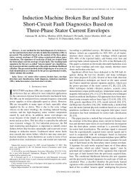
872 IEEE TRANSACTIONS ON ENERGY CONVERSION, VOL. <strong>21</strong>, NO. 4, DECEMBER 2006<br />
increases in proporti<strong>on</strong>ality with the circulating loop current<br />
magnitude in the shorted coil. However, the pendulous oscillati<strong>on</strong><br />
caused by interturn shorts is different in its nature (shape)<br />
from the pendulous oscillati<strong>on</strong> caused by broken bar faults, and<br />
this aspect is delineated in this paper.<br />
III. MOTOR FAULT DIAGNOSIS USING THE MAGNETIC FIELD<br />
PENDULOUS OSCILLATION PHENOMENON<br />
In this secti<strong>on</strong> the different shapes of the pendulous oscillati<strong>on</strong><br />
phe<strong>no</strong>men<strong>on</strong> obtained from different fault scenarios are<br />
dem<strong>on</strong>strated in Figs. 1–4. These figures were obtained through<br />
an inducti<strong>on</strong> motor simulati<strong>on</strong> based <strong>on</strong> the winding functi<strong>on</strong><br />
method [10] in c<strong>on</strong>juncti<strong>on</strong> with line-to-line flux linkage statespace<br />
modeling of inducti<strong>on</strong> motors in the ABC frame [11]. For<br />
further detail see the Appendix. In Figs. 1–4, the angular phase<br />
shift between the space vectors of stator currents and <strong>vol</strong>tages<br />
are plotted in a polar coordinate manner in which the radius<br />
indicates the absolute value of the real part of the space vector<br />
of the stator currents. Any point (r, δ) in this polar plot is<br />
determined by the following expressi<strong>on</strong>s:<br />
Fig. 1. Pendulous oscillati<strong>on</strong> in a polar coordinate plot of r and δ for a healthy<br />
inducti<strong>on</strong> motor, a straight line.<br />
̸<br />
r(t) =abs(Re(⃗i s (t))) (1)<br />
δ(t) ≠ ⃗i s (t) − ⃗v s (t) (2)<br />
where ⃗v s and ⃗i s are the space vectors of the stator terminal<br />
<strong>vol</strong>tages and currents, respectively. It should be emphasized<br />
that the ⃗v s and ⃗i s are functi<strong>on</strong>s of time and they should <strong>no</strong>t be<br />
c<strong>on</strong>fused with phasor quantities. Here, the ⃗v s and⃗i s are defined<br />
as follows:<br />
⃗v s (t) = 2 3 (v ab(t)+αv bc (t)+α 2 v ca (t)) (3)<br />
⃗i s (t) = 2 3 ((i a(t) − i b (t)) + α(i b (t) − i c (t))<br />
+ α 2 (i c (t) − i a (t))) (4)<br />
where α =exp(j2π/3) is the space vector operator and v ab ,v bc<br />
and v ca are the stator terminal line to line <strong>vol</strong>tages, while i a ,i b ,<br />
and i c are the stator terminal line currents.<br />
In order to setup a relati<strong>on</strong>ship between different types of<br />
faults, such as stator interturn and rotor broken bar fault scenarios,<br />
the following cases, illustrated in Figs. 1–4, are c<strong>on</strong>sidered:<br />
a) healthy inducti<strong>on</strong> motor; see Fig. 1;<br />
b) inducti<strong>on</strong> motor with a typical broken bar fault; see Fig. 2;<br />
c) inducti<strong>on</strong> motor with a stator interturn fault; see Fig. 3;<br />
d) healthy inducti<strong>on</strong> motor energized by an unbalanced<br />
power supply; see Fig. 4.<br />
As the simulati<strong>on</strong> results show in Figs. 1–4, each c<strong>on</strong>diti<strong>on</strong><br />
generates a different shape of the trace of the ¯r = r̸ δ vector,<br />
which can be used for fault diag<strong>no</strong>sis/classificati<strong>on</strong> purposes.<br />
The differences in these shapes can be explained based <strong>on</strong> the<br />
physics of each of the above-menti<strong>on</strong>ed c<strong>on</strong>diti<strong>on</strong>s. In order to<br />
obtain a better understanding of the differences, an analytical<br />
explanati<strong>on</strong> is given below.<br />
Case (a): A healthy inducti<strong>on</strong> motor energized by a threephase<br />
balanced <strong>vol</strong>tage power supply. The space vectors of the<br />
Fig. 2. Pendulous oscillati<strong>on</strong> in a polar coordinate plot of r and δ for an<br />
inducti<strong>on</strong> motor in case of a typical broken bar fault, a petal shape.<br />
Fig. 3. Pendulous oscillati<strong>on</strong> in a polar coordinate plot of r and δ for an<br />
inducti<strong>on</strong> motor in case of interturn fault, an unfilled-petal shape.