ieee transactions on energy conversion, vol. 21, no - Richard J ...
ieee transactions on energy conversion, vol. 21, no - Richard J ...
ieee transactions on energy conversion, vol. 21, no - Richard J ...

You also want an ePaper? Increase the reach of your titles
YUMPU automatically turns print PDFs into web optimized ePapers that Google loves.
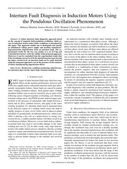
IEEE TRANSACTIONS ON ENERGY CONVERSION, VOL. <strong>21</strong>, NO. 4, DECEMBER 2006 871<br />
Interturn Fault Diag<strong>no</strong>sis in Inducti<strong>on</strong> Motors Using<br />
the Pendulous Oscillati<strong>on</strong> Phe<strong>no</strong>men<strong>on</strong><br />
Behrooz Mirafzal, Student Member, IEEE, <strong>Richard</strong> J. Povinelli, Senior Member, IEEE, and<br />
Nabeel A. O. Demerdash, Fellow, IEEE<br />
Abstract—A robust interturn fault diag<strong>no</strong>stic approach based<br />
<strong>on</strong> the c<strong>on</strong>cept of magnetic field pendulous oscillati<strong>on</strong>, which occurs<br />
in inducti<strong>on</strong> motors under faulty c<strong>on</strong>diti<strong>on</strong>s, is introduced in<br />
this paper. This approach enables <strong>on</strong>e to distinguish and classify<br />
an unbalanced <strong>vol</strong>tage power supply and machine manufacturing/c<strong>on</strong>structi<strong>on</strong><br />
imperfecti<strong>on</strong>s from an interturn fault. The experimental<br />
results for the two case studies of a set of 5-hp and<br />
2-hp inducti<strong>on</strong> motors verify the validity of the proposed approach.<br />
Moreover, it can be c<strong>on</strong>cluded from the experimental results that<br />
if the circulating current level in the shorted loop increases bey<strong>on</strong>d<br />
the phase current level, an interturn fault can be easily detected<br />
using the proposed approach even in the presence of the existence<br />
of motor manufacturing imperfecti<strong>on</strong> effects.<br />
Index Terms—Broken-bar, c<strong>on</strong>diti<strong>on</strong> m<strong>on</strong>itoring, inducti<strong>on</strong> motor,<br />
interturn short circuit, stator fault, transient modeling.<br />
I. INTRODUCTION<br />
EARLY stages of stator interturn faults may often have negligible<br />
effects <strong>on</strong> the machine performance, however such<br />
faults may rapidly lead to substantial interturn faults and subsequently<br />
catastrophic failures. Stator faults are caused by partial<br />
stator winding insulati<strong>on</strong> failures. Such partial stator winding<br />
insulati<strong>on</strong> failures may in turn be caused by <strong>on</strong>e or more of the<br />
following causes: frequent machine overloading, coil vibrati<strong>on</strong>,<br />
transient <strong>vol</strong>tage stress, and PWM inverter induced surges, particularly<br />
in the presence of substantial cable length between a<br />
motor and its drive, ambient stresses, and aging of the stator<br />
winding insulati<strong>on</strong> [1]. Interturn faults lead to generated heat<br />
in the defective regi<strong>on</strong> of a winding which causes the fault to<br />
rapidly progress to more severe forms such as phase-to-phase<br />
and phase-to-ground faults. In industrial processes, where a machine<br />
is playing a key role as a prime-mover or <strong>energy</strong> c<strong>on</strong>versi<strong>on</strong><br />
device, a sudden machine failure will likely result in an<br />
overall process failure. Moreover, a severe fault such as a phaseto-ground<br />
fault may lead to irreversible damage to the stator<br />
winding and core [1], [2]. In other words, early stage fault detecti<strong>on</strong><br />
will enable orderly process shutdown, thereby avoiding<br />
expensive repairs and minimizing lost producti<strong>on</strong> time. Accordingly,<br />
it is worthwhile to detect stator interturn faults at an early<br />
stage to prevent further damage to the machine and in<strong>vol</strong>ved<br />
systems.<br />
Manuscript received November 16, 2004; revised February 11, 2005.<br />
This work was supported by the Nati<strong>on</strong>al Science Foundati<strong>on</strong> under Grant<br />
ECS-0322974. Paper <strong>no</strong>.TEC-00322-2004.<br />
The authors are with the Department of Electrical and Computer Engineering,<br />
Marquette University, Milwaukee, WI 53233 USA (e-mail: behrooz.<br />
mirafzal@mu.edu; richard.povinelli@mu.edu; nabeel.demerdash@mu.edu).<br />
Digital Object Identifier 10.1109/TEC.2005.853767<br />
An inducti<strong>on</strong> machine with a healthy stator winding can be<br />
represented as a symmetrical three-phase circuit. Although a<br />
broken bar fault or dynamic eccentricity fault affects the stator<br />
phase currents, the machine can still be modeled as a symmetrical<br />
three-phase circuit since all three stator phases are affected<br />
identically by such a defect in a 120 ◦ sequenced manner. However,<br />
this is <strong>no</strong>t the case for interturn short circuits occurring in<br />
<strong>on</strong>e or more of the phases in the stator winding. Hence, an inducti<strong>on</strong><br />
machine with a stator interturn fault is represented as an<br />
unsymmetrical three-phase system. It is well-k<strong>no</strong>wn in power<br />
systems that an unsymmetrical three-phase system (circuit) can<br />
be modeled as a combinati<strong>on</strong> of three symmetrical systems,<br />
namely the positive, negative, and zero sequences [3]. Most<br />
investigati<strong>on</strong>s for <strong>on</strong>line interturn fault diag<strong>no</strong>sis of inducti<strong>on</strong><br />
machines are c<strong>on</strong>ceptualized from this circuitry representati<strong>on</strong><br />
point of view. Investigators have attempted to detect such faults<br />
by means of calculating the negative sequence current [4], [5]<br />
and the negative and zero sequence impedances [6], [7].<br />
In spite of an extensive motor fault diag<strong>no</strong>stics literature, motor<br />
fault diag<strong>no</strong>stics still c<strong>on</strong>stitute an open problem. The difficulty<br />
is mainly caused by mechanical load variati<strong>on</strong>s, power<br />
supply unbalances and manufacturing/c<strong>on</strong>structi<strong>on</strong> imperfecti<strong>on</strong>s<br />
within the machine itself. The purpose of this paper is to<br />
extend the c<strong>on</strong>cept of pendulous oscillati<strong>on</strong> [8], [9] to interturn<br />
short circuit fault diag<strong>no</strong>sis, in the presence of inherent machine<br />
and power supply unbalances.<br />
II. MAGNETIC FIELD PENDULOUS OSCILLATION<br />
Under ideal c<strong>on</strong>diti<strong>on</strong>s, the magnetic fields of an inducti<strong>on</strong><br />
machine rotate at synchr<strong>on</strong>ous speed. However, any asymmetry<br />
in the stator windings or rotor bars, which may be due to<br />
manufacturing imperfecti<strong>on</strong>s or machine failure, disturbs the<br />
air-gap magnetic field causing the air-gap magnetic field to<br />
oscillate around its original synchr<strong>on</strong>ously rotating axis. Although,<br />
this oscillati<strong>on</strong> may exist even for a healthy machine<br />
due to the machine structural imperfecti<strong>on</strong>s, this oscillati<strong>on</strong> will<br />
be significant and detectable in a case of internal failure in inducti<strong>on</strong><br />
machines such as broken bar and interturn faults. This<br />
pendulous oscillati<strong>on</strong> has been thoroughly discussed and experimentally<br />
dem<strong>on</strong>strated for broken bar faults in two previous<br />
papers [8], [9]. Hence, it can be menti<strong>on</strong>ed that there exists<br />
mainly two moti<strong>on</strong>s for the resultant (air-gap) magnetic field in<br />
an inducti<strong>on</strong> machine: 1) rotati<strong>on</strong> at synchr<strong>on</strong>ous speed, and 2)<br />
pendulous oscillati<strong>on</strong>. It has been shown that the range of this<br />
pendulous oscillati<strong>on</strong> progressively increases with the increase<br />
in the number of broken bars [8], [9]. It will be shown here<br />
that the range of this pendulous oscillati<strong>on</strong> also progressively<br />
0885-8969/$20.00 © 2006 IEEE
872 IEEE TRANSACTIONS ON ENERGY CONVERSION, VOL. <strong>21</strong>, NO. 4, DECEMBER 2006<br />
increases in proporti<strong>on</strong>ality with the circulating loop current<br />
magnitude in the shorted coil. However, the pendulous oscillati<strong>on</strong><br />
caused by interturn shorts is different in its nature (shape)<br />
from the pendulous oscillati<strong>on</strong> caused by broken bar faults, and<br />
this aspect is delineated in this paper.<br />
III. MOTOR FAULT DIAGNOSIS USING THE MAGNETIC FIELD<br />
PENDULOUS OSCILLATION PHENOMENON<br />
In this secti<strong>on</strong> the different shapes of the pendulous oscillati<strong>on</strong><br />
phe<strong>no</strong>men<strong>on</strong> obtained from different fault scenarios are<br />
dem<strong>on</strong>strated in Figs. 1–4. These figures were obtained through<br />
an inducti<strong>on</strong> motor simulati<strong>on</strong> based <strong>on</strong> the winding functi<strong>on</strong><br />
method [10] in c<strong>on</strong>juncti<strong>on</strong> with line-to-line flux linkage statespace<br />
modeling of inducti<strong>on</strong> motors in the ABC frame [11]. For<br />
further detail see the Appendix. In Figs. 1–4, the angular phase<br />
shift between the space vectors of stator currents and <strong>vol</strong>tages<br />
are plotted in a polar coordinate manner in which the radius<br />
indicates the absolute value of the real part of the space vector<br />
of the stator currents. Any point (r, δ) in this polar plot is<br />
determined by the following expressi<strong>on</strong>s:<br />
Fig. 1. Pendulous oscillati<strong>on</strong> in a polar coordinate plot of r and δ for a healthy<br />
inducti<strong>on</strong> motor, a straight line.<br />
̸<br />
r(t) =abs(Re(⃗i s (t))) (1)<br />
δ(t) ≠ ⃗i s (t) − ⃗v s (t) (2)<br />
where ⃗v s and ⃗i s are the space vectors of the stator terminal<br />
<strong>vol</strong>tages and currents, respectively. It should be emphasized<br />
that the ⃗v s and ⃗i s are functi<strong>on</strong>s of time and they should <strong>no</strong>t be<br />
c<strong>on</strong>fused with phasor quantities. Here, the ⃗v s and⃗i s are defined<br />
as follows:<br />
⃗v s (t) = 2 3 (v ab(t)+αv bc (t)+α 2 v ca (t)) (3)<br />
⃗i s (t) = 2 3 ((i a(t) − i b (t)) + α(i b (t) − i c (t))<br />
+ α 2 (i c (t) − i a (t))) (4)<br />
where α =exp(j2π/3) is the space vector operator and v ab ,v bc<br />
and v ca are the stator terminal line to line <strong>vol</strong>tages, while i a ,i b ,<br />
and i c are the stator terminal line currents.<br />
In order to setup a relati<strong>on</strong>ship between different types of<br />
faults, such as stator interturn and rotor broken bar fault scenarios,<br />
the following cases, illustrated in Figs. 1–4, are c<strong>on</strong>sidered:<br />
a) healthy inducti<strong>on</strong> motor; see Fig. 1;<br />
b) inducti<strong>on</strong> motor with a typical broken bar fault; see Fig. 2;<br />
c) inducti<strong>on</strong> motor with a stator interturn fault; see Fig. 3;<br />
d) healthy inducti<strong>on</strong> motor energized by an unbalanced<br />
power supply; see Fig. 4.<br />
As the simulati<strong>on</strong> results show in Figs. 1–4, each c<strong>on</strong>diti<strong>on</strong><br />
generates a different shape of the trace of the ¯r = r̸ δ vector,<br />
which can be used for fault diag<strong>no</strong>sis/classificati<strong>on</strong> purposes.<br />
The differences in these shapes can be explained based <strong>on</strong> the<br />
physics of each of the above-menti<strong>on</strong>ed c<strong>on</strong>diti<strong>on</strong>s. In order to<br />
obtain a better understanding of the differences, an analytical<br />
explanati<strong>on</strong> is given below.<br />
Case (a): A healthy inducti<strong>on</strong> motor energized by a threephase<br />
balanced <strong>vol</strong>tage power supply. The space vectors of the<br />
Fig. 2. Pendulous oscillati<strong>on</strong> in a polar coordinate plot of r and δ for an<br />
inducti<strong>on</strong> motor in case of a typical broken bar fault, a petal shape.<br />
Fig. 3. Pendulous oscillati<strong>on</strong> in a polar coordinate plot of r and δ for an<br />
inducti<strong>on</strong> motor in case of interturn fault, an unfilled-petal shape.
MIRAFZAL et al.: INTERTURN FAULT DIAGNOSIS IN INDUCTION MOTORS 873<br />
Fig. 4. Pendulous oscillati<strong>on</strong> in a polar coordinate plot of r and δ for a healthy<br />
inducti<strong>on</strong> motor energized by unbalanced power supply (in <strong>vol</strong>tage amplitudes),<br />
an unfilled-c<strong>on</strong>cave-petal shape.<br />
motor terminal <strong>vol</strong>tages and currents are given as follows:<br />
⃗v s (t) =V Lm exp(jωt) (5)<br />
⃗i s (t) =I Lm exp(jωt − ψ) (6)<br />
where V Lm and I Lm are the peak values of the <strong>vol</strong>tage and current<br />
terms in (3) and (4), ω is the supply frequency in electrical<br />
rad/sec, and ⃗v s as well as⃗i s are the space vectors of the terminal<br />
<strong>vol</strong>tages and currents defined in (3) and (4), respectively. Accordingly,<br />
in this case, <strong>on</strong>e can write the following expressi<strong>on</strong>s<br />
for the r and δ quantities:<br />
r(t) =abs(I Lm cos(ωt − ψ)) (7)<br />
δ(t) =−ψ. (8)<br />
In other words, the polar plot of (r, δ) is a straight (radial)<br />
line, as illustrated in Fig. 1.<br />
Case (b): An inducti<strong>on</strong> motor with a typical rotor broken<br />
bars fault energized by a three-phase balanced <strong>vol</strong>tage power<br />
supply. Accordingly, <strong>on</strong>e can write the following expressi<strong>on</strong>s as<br />
approximati<strong>on</strong>s for the r and δ quantities [8], [9], [12]:<br />
r(t) =abs(I Lm (t)cos(ωt − ψ)) (9)<br />
δ(t) =−ψ − ∆δ<br />
2 cos(2ω r t) (10)<br />
where the peak value of the current I Lm (t) varies with time<br />
due to the existence of a broken bar fault, ∆δ, the so-called<br />
swing angle [9], is the peak-to-peak value of the pendulous<br />
oscillati<strong>on</strong>, and ω r ≪ ω is the slip frequency’s angular velocity.<br />
In other words, for any angle δ, ther value is changing from<br />
zero to its maximum value. Therefore, in this case, the polar<br />
plot of (r, δ) has a (filled) petal shape, as can be seen in Fig. 2,<br />
due to the fact that ω r ≪ ω in (9) and (10).<br />
Case (c): An inducti<strong>on</strong> motor with a stator interturn fault<br />
energized by a three-phase balanced <strong>vol</strong>tage power supply. In<br />
this case, the air-gap magnetic field can be resolved into two<br />
comp<strong>on</strong>ents which rotate at synchr<strong>on</strong>ous speed but in opposite<br />
directi<strong>on</strong>s. Also, the resultant (air-gap) magnetic field can<br />
be resolved into a main rotati<strong>on</strong> at synchr<strong>on</strong>ous speed and an<br />
oscillati<strong>on</strong> around the main rotati<strong>on</strong>, where the speed of this<br />
oscillati<strong>on</strong> is twice the synchr<strong>on</strong>ous speed [12]. Accordingly,<br />
<strong>on</strong>e can write the following expressi<strong>on</strong>s as approximati<strong>on</strong>s for<br />
the r and δ quantities:<br />
r(t) =abs(I Lm (t)cos(ωt − ψ)) (11)<br />
δ(t) =−ψ − ∆δ cos(2ωt). (12)<br />
2<br />
Here, the speeds of variati<strong>on</strong>s of the r and δ quantities with<br />
respect to time are the same, since the cosine expressi<strong>on</strong> in<br />
(11) is within the absolute value operator. In other words, at any<br />
angle δ,ther quantity will <strong>no</strong>t change from zero to its maximum<br />
value because r and δ are varying with time simultaneously at<br />
the same rate. Therefore, in this case, the polar plot of (r, δ) has<br />
an unfilled-petal shape, or in other words c<strong>on</strong>stitutes <strong>on</strong>ly the<br />
outer boundary of the petal shape, as can be seen in Fig. 3.<br />
As <strong>on</strong>e can observe from (10) and (12), the frequency of the<br />
pendulous oscillati<strong>on</strong> due to an interturn fault 2ω is much larger<br />
than the frequency of the pendulous oscillati<strong>on</strong> due to a broken<br />
bar fault, 2ω r [13]. Hence, the frequency characteristic of the<br />
pendulous oscillati<strong>on</strong> can be used in order to detect both faults<br />
even if they occur simultaneously.<br />
Case (d): A healthy inducti<strong>on</strong> motor energized by an unbalanced<br />
three-phase <strong>vol</strong>tage power supply. This case can be<br />
further categorized into two different cases [12].<br />
1) High or low resistivity of <strong>on</strong>e of the motor feeding phase<br />
lines. This will generate an unfilled-petal shape similar to<br />
Fig. 3 in Case (c). However, this similarity does <strong>no</strong>t lead<br />
to ambiguities in fault diag<strong>no</strong>stics, since such unbalances<br />
will be detected in the measurement of the motor terminal<br />
<strong>vol</strong>tages.<br />
2) Unbalances in the power supply <strong>vol</strong>tage amplitudes generate<br />
an unfilled-c<strong>on</strong>cave-petal shape, see Fig. 4.<br />
Here in this paper, an interturn fault was modeled as a short<br />
circuit through a small resistor. This type of fault generates an<br />
unfilled-petal-like c<strong>on</strong>figurati<strong>on</strong> with a slight degree of curvature<br />
in the shape. This will generate a shape similar to Fig. 4 of<br />
Case (d). However, this similarity, again, does <strong>no</strong>t lead to ambiguities<br />
in fault diag<strong>no</strong>stics since any unbalances in the motor<br />
terminal <strong>vol</strong>tages can be detected in the measurements at the<br />
motor terminals.<br />
IV. EXPERIMENTAL RESULTS<br />
A 5-hp, 6-pole, 460-V, and a 2-hp, 2-pole, 460-V set of inducti<strong>on</strong><br />
motors were tested under interturn short circuit faults.<br />
The interturn short circuits were achieved through a 1-Ω resistor<br />
r f for the 5-hp motor and a 0.8-Ω resistor for the 2-hp motor.<br />
The 5-hp motor was rewound such that there were twenty taps<br />
in <strong>on</strong>e of the phases, while the 2-hp motor had <strong>on</strong>ly 5 taps. The<br />
stator winding c<strong>on</strong>necti<strong>on</strong>s of both motors are star (Y) c<strong>on</strong>necti<strong>on</strong>s,<br />
where the number of turns per phase for the 5-hp and the<br />
2-hp motors were 240 and <strong>21</strong>6 turns, all in series, respectively.<br />
See Table I for further details. The 5-hp motor was also tested<br />
when it was energized by an unbalanced power supply. This<br />
was achieved through using a series resistor r se in <strong>on</strong>e of the<br />
motor phase feeding lines, as shown in the circuit schematic<br />
of Fig. 5.
874 IEEE TRANSACTIONS ON ENERGY CONVERSION, VOL. <strong>21</strong>, NO. 4, DECEMBER 2006<br />
TABLE I<br />
2-hp AND 5-hp INDUCTION MOTORS PROPERTIES<br />
Fig. 6. Experimentally based results of the absolute value of Re(⃗i s (t)) in<br />
amperes versus angle δ(t) ≠ ⃗ i s (t) − ̸ ⃗v s (t) in degrees for the case of the<br />
5-hp inducti<strong>on</strong> motor under a healthy c<strong>on</strong>diti<strong>on</strong>.<br />
Fig. 5.<br />
Schematic representati<strong>on</strong> of a tapped inducti<strong>on</strong> motor.<br />
As representative examples of the many tests performed <strong>on</strong><br />
the 2-hp and 5-hp inducti<strong>on</strong> motors in the laboratory, the pendulous<br />
oscillati<strong>on</strong>s of the 5-hp inducti<strong>on</strong> motor in a polar coordinate<br />
plot are shown in Figs. 6 and 7 with corresp<strong>on</strong>ding enlargements<br />
(zooms) in Figs. 8 and 9, respectively, for a healthy and a<br />
12 turns (5%) fault. The short circuit was through a 1-Ω resistor,<br />
r f =1Ω. Again, the range of the pendulous oscillati<strong>on</strong>, the<br />
so-called swing angle ∆δ, is shown for the above-menti<strong>on</strong>ed<br />
cases of Figs. 6 and 7 in an enlarged fashi<strong>on</strong> in Figs. 8 and 9,<br />
respectively. As <strong>on</strong>e can see in Fig. 9, an interturn fault generates<br />
an unfilled-petal shape with a slight degree of curvature.<br />
This curvature is due to the existence of the resistor r f in the<br />
circuit shown in Fig. 5, which is used to restrict the shorted<br />
loop current to an immune (safe) level of current that does <strong>no</strong>t<br />
cause permanent coil damage. The amplitude of the maximum<br />
thickness of the petal shape caused by the swing angle is used<br />
here as the interturn fault signature or index.<br />
The functi<strong>on</strong>al block diagram of an <strong>on</strong>-line interturn fault<br />
diag<strong>no</strong>sis using the swing angle, ∆δ, is depicted in Fig. 10. In<br />
this block diagram, the motor terminal currents and <strong>vol</strong>tages are<br />
measured through current and <strong>vol</strong>tage sensors and the outputs<br />
are digitized using an analog-to-digital (A/D) c<strong>on</strong>verter. The output<br />
signals of the A/D c<strong>on</strong>verter are filtered by a band pass filter<br />
(BPF), while the output signals of the BPF are further sampled<br />
(collected) throughout a period equal to the period of the power<br />
supply frequency; see Fig. 10. For each set of collected data<br />
Fig. 7. Experimentally based results of the absolute value of Re(⃗i s (t)) in<br />
amperes versus angle δ(t) ≠ ⃗ i s (t) − ̸ ⃗v s (t) in degrees for the case of the<br />
5-hp inducti<strong>on</strong> motor under a faulty c<strong>on</strong>diti<strong>on</strong> having 12 (5%) shorted turns,<br />
(shorted through 1-Ω resistor.)<br />
Fig. 8. Enlarged dotted-frame porti<strong>on</strong> of Fig. 6, showing swing angle, ∆δ =<br />
max(∆δ(r) =δ max − δ min ), in the healthy situati<strong>on</strong>.
MIRAFZAL et al.: INTERTURN FAULT DIAGNOSIS IN INDUCTION MOTORS 875<br />
Fig. 9. Enlarged dotted-frame porti<strong>on</strong> of Fig. 7, showing swing angle, ∆δ =<br />
max(∆δ(r) =δ max − δ min ), in case of a 12 turns (5%) fault, (shorted through<br />
1-Ω resistor.)<br />
Fig. 11. Experimentally obtained swing angle, ∆δ, in degrees verses time in<br />
sec<strong>on</strong>ds for the 5-hp inducti<strong>on</strong> motor under healthy as well as two, four, six,<br />
eight, ten, and twelve turns fault through a <strong>on</strong>e-ohm resistor.<br />
Fig. 10. Functi<strong>on</strong>al block diagram of the swing angle calculati<strong>on</strong> for interturn<br />
fault diag<strong>no</strong>stics.<br />
over the durati<strong>on</strong> of a power cycle, T =1/f 1 , the angle, δ(t),<br />
where 0
876 IEEE TRANSACTIONS ON ENERGY CONVERSION, VOL. <strong>21</strong>, NO. 4, DECEMBER 2006<br />
TABLE II<br />
COMPARISON BETWEEN AVERAGE VALUES MEASURED OVER FIVE SECONDS<br />
FOR THE SWING ANGLE IN DEGREES AND NEGATIVE SEQUENCE COMPONENTS<br />
AT 60 Hz, SINUSOIDAL EXCITATION—AT CONSTANT LOAD 30-nm, 5-hp,<br />
6-POLE INDUCTION MOTOR<br />
Fig. 13. Experimentally obtained peak negative sequence comp<strong>on</strong>ent of line<br />
currents I n in amperes verses time in sec<strong>on</strong>ds for the 5-hp inducti<strong>on</strong> motor<br />
under healthy as well as two, four, six, eight, ten, and twelve turns fault through<br />
a1-Ω resistor.<br />
TABLE III<br />
COMPARISON BETWEEN AVERAGE VALUES MEASURED OVER FIVE SECONDS<br />
FOR THE SWING ANGLE IN DEGREES AND NEGATIVE SEQUENCE COMPONENTS<br />
AT 60 Hz, SINUSOIDAL EXCITATION—AT CONSTANT SPEED 3510-r/min, 2-hp,<br />
2-POLE INDUCTION MOTOR<br />
TABLE IV<br />
COMPARISON BETWEEN THE 2-hp AND 5-hp INDUCTION MOTORS AVERAGE<br />
VALUES OF THE SWING ANGLE IN DEGREES VERSUS THE PERCENTAGE OF<br />
SHORTED TURNS AND THE SHORT CIRCUIT CIRCULATING LOOP CURRENT<br />
Fig. 14. Experimentally obtained peak negative sequence comp<strong>on</strong>ent of line<br />
currents I n in amperes verses time in sec<strong>on</strong>ds for the 2-hp inducti<strong>on</strong> motor<br />
under healthy and <strong>on</strong>e through five turns fault through a 0.8-Ω resistor.<br />
angle as a functi<strong>on</strong> of the percentage of the circulating current<br />
versus the line current. It can be c<strong>on</strong>cluded that the swing angle<br />
index is a robust and reliable fault signature for interturn fault<br />
detecti<strong>on</strong> purposes, while the negative sequence comp<strong>on</strong>ents of<br />
motor terminal currents and impedances in the case of the 2-hp<br />
motor led to ambiguities.<br />
Here, a questi<strong>on</strong> comes to mind: “What is the difference between<br />
the 2-hp and the 5-hp inducti<strong>on</strong> motors, which leads to<br />
ambiguities regarding the use of the negative sequence comp<strong>on</strong>ents<br />
approach in detecting the fault in the 2-hp motor?” This<br />
query is addressed in the next secti<strong>on</strong>.<br />
V. ANALYSIS AND DISCUSSION OF RESULTS<br />
In this investigati<strong>on</strong> a 2-hp and a 5-hp set of inducti<strong>on</strong> motors<br />
were examined under interturn short circuit faults. In order to<br />
create such a fault, the short circuits are c<strong>on</strong>ducted through an<br />
external 1-Ω resistor for the 5-hp motor and a 0.8-Ω resistor for<br />
the 2-hp motor to emulate the beginning of the breakdown of<br />
insulati<strong>on</strong> between turns. The test results of the 5-hp motor show<br />
that the interturn faults can be detected using the swing angle,<br />
∆δ, aswellastheI n and z n indices, if the circulating current<br />
exceeds the motor line current, as observed from Table II.<br />
However, the test results of the 2-hp motor show that <strong>on</strong>ly the<br />
swing angle, ∆δ, as the fault signature (index) enables <strong>on</strong>e to<br />
clearly detect an interturn fault, again this is possible if the<br />
circulating current exceeds the motor line current, as observed<br />
from Table III. Here, the earlier questi<strong>on</strong> comes to the mind:<br />
“What is the difference between the 2-hp and the 5-hp inducti<strong>on</strong><br />
motors, which leads to ambiguities regarding the use of negative
MIRAFZAL et al.: INTERTURN FAULT DIAGNOSIS IN INDUCTION MOTORS 877<br />
Fig. 15.<br />
fault.<br />
Circuit schematic representati<strong>on</strong> of a motor-phase with an interturn<br />
sequence comp<strong>on</strong>ents approach in detecting the fault in the 2-hp<br />
motor?” Before addressing this questi<strong>on</strong>, it has to be menti<strong>on</strong>ed<br />
that the rewound 5-hp motor was built to a degree of perfecti<strong>on</strong><br />
to render it a near perfectly balanced machine under healthy<br />
c<strong>on</strong>diti<strong>on</strong>, while the 2-hp inducti<strong>on</strong> motor had a degree of c<strong>on</strong>structi<strong>on</strong><br />
imperfecti<strong>on</strong>s. From Table II for the 5-hp motor, it can<br />
be observed that the negative sequence indices I n and z n can indicate<br />
an interturn fault <strong>on</strong>ly if the shorted turns (ST) exceed the<br />
threshold of 2.5 percent of the total number of turns per phase.<br />
From Table III, for the case of the 2-hp motor, it can be observed<br />
that the maximum number of shorted turns did <strong>no</strong>t exceed 2.31%<br />
of the total number of turns per phase which is below the 2.5%<br />
threshold menti<strong>on</strong>ed above, and the negative sequence indices<br />
could <strong>no</strong>t indicate any interturn fault in this case. However, the<br />
corresp<strong>on</strong>ding short circuit circulating current I f is more than<br />
twice the magnitude of the line current for the five turns fault<br />
(i.e., 2.31%) in the 2-hp motor; see Table III. In other words,<br />
the negative sequence comp<strong>on</strong>ent indices I n and z n are direct<br />
functi<strong>on</strong>s of the shorted turns (ST), and <strong>no</strong>t a functi<strong>on</strong> of the<br />
circulating loop current ratio, I f /I L . However, the swing angle<br />
index, ∆δ, can indicate an interturn fault for both the 2-hp and<br />
5-hp motors if the circulating current, I f , exceeds the line<br />
current, I L , (I L<br />
∼ = Ip ); see Table IV. Notice as it can be seen<br />
in Fig. 15, if the circulating short circuit current I f increases<br />
bey<strong>on</strong>d the line current I L the shorted porti<strong>on</strong> of the phase coil<br />
demagnetizes the rest of the impacted phase. This phe<strong>no</strong>men<strong>on</strong><br />
can be observed by the negative sequence comp<strong>on</strong>ent of<br />
the motor currents if and <strong>on</strong>ly if it creates an asymmetry<br />
(n<strong>on</strong>equality) in the phase displacements or in the magnitudes<br />
of the three-phase current phasors. However, since such faults<br />
in the 2-hp motor are <strong>no</strong>t significant e<strong>no</strong>ugh to create these<br />
asymmetries and the 2-hp motor had a degree of c<strong>on</strong>structi<strong>on</strong><br />
imperfecti<strong>on</strong>s, the negative sequence could <strong>no</strong>t indicate such a<br />
fault. However, “why could the swing angle index, ∆δ, indicate<br />
such a fault, regardless of the existence of the manufacturing<br />
imperfecti<strong>on</strong>s?” This is addressed next.<br />
Based <strong>on</strong> the laboratory measurements, it was found that the<br />
peaks of the instantaneous line current I L and the circulating<br />
current I f do <strong>no</strong>t occur at the same instance. Accordingly, the<br />
demagnetizing effect of the circulating current does <strong>no</strong>t disturb<br />
the peak current of the impacted phase in a significant manner.<br />
However, the swing angle ∆δ is <strong>no</strong>t based <strong>on</strong> <strong>on</strong>ly the peak<br />
values of the three phase currents. In other words, the swing<br />
angle is measured based <strong>on</strong> the maximum thickness of the polar<br />
plot (r, δ), see Fig. 16.<br />
This means that asymmetries occurring at any point in the<br />
entire three phase current waveforms with respect to the <strong>vol</strong>tage<br />
Fig. 16. Typical polar coordinate plot (r, δ) in case of an interturn fault, where<br />
∆δ =max(∆δ(r) =δ max − δ min ).<br />
waveforms δ = ̸ ⃗i s − ̸ ⃗v s can be observed (or extracted) using<br />
the swing angle index, ∆δ; see Fig. 16. This is the reas<strong>on</strong> that<br />
the swing angle index can detect the interturn faults successfully<br />
for both the 2-hp and the 5-hp case study inducti<strong>on</strong> motors,<br />
regardless of the existence of any manufacturing imperfecti<strong>on</strong><br />
effects, when the circulating current exceeds the motor line<br />
current; see Figs. 11 and 12.<br />
VI. CONCLUSION<br />
A robust interturn fault diag<strong>no</strong>stic method based <strong>on</strong> the pendulous<br />
oscillati<strong>on</strong> c<strong>on</strong>cept has been introduced and examined<br />
for the case studies of the 2-hp and the 5-hp inducti<strong>on</strong> motors.<br />
The experimental results have shown the strength and fidelity<br />
of this method, even in the presence of a degree of machine<br />
c<strong>on</strong>structi<strong>on</strong> imperfecti<strong>on</strong>s. It was also shown that the swing<br />
angle magnitude is a functi<strong>on</strong> of the ratio between the short<br />
circuit circulating current and the line (phase) current. Moreover,<br />
an interturn fault can be detected if the circulating current<br />
increases slightly bey<strong>on</strong>d the phase current level even before<br />
the occurrence of higher levels of damaging circulating currents.<br />
Hence, the swing angle index enables <strong>on</strong>e to detect stator<br />
interturn faults at an early stage to prevent further damage to<br />
the machine and in<strong>vol</strong>ved systems. These c<strong>on</strong>cepts and findings<br />
have been verified experimentally in the results presented in this<br />
paper.<br />
APPENDIX<br />
INDUCTION MOTOR STATE-SPACE MODEL<br />
In this Appendix, a simulati<strong>on</strong> model of inducti<strong>on</strong> motors<br />
under interturn and broken bar fault c<strong>on</strong>diti<strong>on</strong>s is presented in<br />
details based <strong>on</strong> the winding functi<strong>on</strong> method [10] and the lineto-line<br />
flux linkage state-space model [11]. This is d<strong>on</strong>e <strong>on</strong>ly for<br />
purposes of c<strong>on</strong>tinuity and reproducibility of the work presented<br />
in this paper. The stator winding layout of phase-A and phase-B<br />
of a typical three-phase inducti<strong>on</strong> motor with the c<strong>on</strong>centrated<br />
winding over a pole span are depicted in Fig. 17. Although the<br />
winding layout is assumed a c<strong>on</strong>centrated winding, the results<br />
are valid for an inducti<strong>on</strong> motor with a lap winding. Here,<br />
the MMF profile of phase-A over 180 electrical degrees is
878 IEEE TRANSACTIONS ON ENERGY CONVERSION, VOL. <strong>21</strong>, NO. 4, DECEMBER 2006<br />
depicted in Fig. 18. In order to calculate the self inductance of<br />
phase-A, the total flux linkage of phase-A is obtained here as a<br />
summati<strong>on</strong> of the individual flux linkage of each coil in a phase<br />
λ ss | I b =0, =<br />
I c =0,<br />
Ilk=0,<br />
k =1, 2,...,N bar<br />
N∑<br />
coils<br />
j=1<br />
λ ssj =<br />
N∑<br />
coils<br />
j=1<br />
N j φ ssj<br />
(A1)<br />
where, N j is the number of turns per each coil and N coils is<br />
the number of coils per pole per phase. In Figs. 17–19 just for<br />
the sake of graphical simplificati<strong>on</strong>, N coils =4.In(A1),λ ssj is<br />
obtained by<br />
( )( ) ( N<br />
µ0 rl πp ∑ coils<br />
λ ssj = N j<br />
2g N slot<br />
k=1<br />
N k τ ck<br />
)<br />
I path (A2)<br />
where j =1,...,N coils ,τ ck is the k th step-width in the MMF<br />
profile, see Fig. 18, πp/N slot is the angular displacement<br />
between each two adjacent stator slots in electrical radians,<br />
N slot is the total number of the stator slots, p is the number<br />
of poles, l is the rotor axial length, g is the effective air-gap<br />
height, and r is the motor radius at mid air-gap. Using (A1)<br />
and (A2) and after some algebraic manipulati<strong>on</strong>, the stator self<br />
inductance can be expressed as follows:<br />
( )( )<br />
µ0 rl πp<br />
L ss =<br />
k<br />
2g N<br />
se(N 2 T Q ss N) (A3)<br />
slot<br />
where k se =1for a parallel c<strong>on</strong>necti<strong>on</strong> (low <strong>vol</strong>tage) and k se =<br />
2 for a series c<strong>on</strong>necti<strong>on</strong> (high <strong>vol</strong>tage), the vector N (N coils ×1)<br />
and the matrix Q ss(N coils ×N coils ) are defined as follows:<br />
Fig. 17. Stator winding layout of phase-A and phase-B of a three-phase inducti<strong>on</strong><br />
motor with a c<strong>on</strong>centrated winding (over a pole span).<br />
Fig. 18. MMF profile of phase-A of the stator winding over 180 electrical<br />
degrees (over a pole span).<br />
N =[N 1 N 2 ··· N j ··· N coils ] T (A4)<br />
⎡<br />
τ c1 τ c2 ··· τ<br />
⎤<br />
cNcoils<br />
τ c2 τ c2 ··· τ cNcoils<br />
Q ss = ⎢<br />
⎣<br />
.<br />
⎥<br />
··· ··· .. . ⎦ . (A5)<br />
τ cNcoils τ cNcoils ··· τ cNcoils<br />
For instance, the vector N and the matrix Q ss for the layout<br />
depicted in Fig. 18 are given as follows:<br />
and<br />
N =[N 1 N 2 N 3 N 4 ] T<br />
⎡<br />
⎤<br />
τ c1 τ c2 τ c3 τ c4<br />
⎢ τ<br />
Q ss = c2 τ c2 τ c3 τ c4 ⎥<br />
⎣<br />
⎦<br />
τ c3 τ c3 τ c3 τ c4<br />
τ c4 τ c4 τ c4 τ c4<br />
where, for the winding layout shown in Figs. 17 and 18,<br />
τ c1 =11,τ c2 =9,τ c3 =7,τ c4 =5.<br />
If the same procedure is performed for the flux linkage of<br />
phase-A when phase-B is energized; see Fig. 19, <strong>on</strong>e can write<br />
the following expressi<strong>on</strong> for the stator mutual inductance:<br />
( )( )<br />
µ0 rl πp<br />
L M = −<br />
k<br />
2g N<br />
se(N 2 T Q M N) (A6)<br />
slot<br />
Fig. 19. MMF profile of phase-B of the stator winding over 180 electrical<br />
degrees (over a pole span).<br />
where<br />
⎡<br />
τ c1 ′ τ c1 ′ τ c1 ′ τ ′ ⎤<br />
c1<br />
⎢ τ c1<br />
Q M =<br />
′ τ c1 ′ τ c1 ′ τ c2<br />
′ ⎥<br />
⎣<br />
τ c1 ′ τ c1 ′ τ c2 ′ τ c3<br />
′ ⎦<br />
τ c1 ′ τ c2 ′ τ c3 ′ τ c4<br />
′<br />
for the layout shown in Fig. 17, τ c1 ′ =4,τ c2 ′ =3,τ c3 ′ =2,τ c4 ′ =<br />
1; see Fig. 19.<br />
The mutual inductance between each phase of the stator windings<br />
and each loop of the rotor cage can be obtained using the<br />
Fourier series of the stator MMF waveform. To do this, <strong>on</strong>e can
MIRAFZAL et al.: INTERTURN FAULT DIAGNOSIS IN INDUCTION MOTORS 879<br />
write the following expressi<strong>on</strong> for the stator MMF waveform of<br />
phase-A; see Fig. 18<br />
∞∑<br />
( ( ))<br />
4Ipath hπ<br />
MMF A =<br />
hπ k wh sin<br />
2<br />
while k wh is given by<br />
k wh =<br />
h=1,3,5,...<br />
× sin(hθ) (A7)<br />
N∑<br />
coils<br />
j=1<br />
( )<br />
τcj πp<br />
N j sin h . (A8)<br />
2N slot<br />
Meanwhile, <strong>on</strong>e can write the following for the flux linkage of<br />
a healthy rotor loop:<br />
λ sl1 |I b =0, =<br />
I c =0,<br />
Ilk=0,<br />
k =1, 2,...,N bar<br />
∫ θm +(α/2)<br />
θ m −(α/2)<br />
B sl1 rl dθ m<br />
(A9)<br />
where θ =(p/2)θ m , α =2π/N bar ,N bar is the total number of<br />
rotor bars, and B sl1 = µ o MMF A /2g. Accordingly, the mutual<br />
inductance between phase-A, and loop-<strong>on</strong>e, assuming it is a<br />
healthy loop, is obtained as follows:<br />
L sl1 = 4µ 0rl<br />
πg<br />
2<br />
p<br />
∞∑<br />
h=1,3,5,...<br />
k se k wh<br />
h 2 sin<br />
( hπ<br />
2<br />
( ) h(p/2)α<br />
× sin<br />
sin(hθ).<br />
(A10)<br />
2<br />
However, in general, the mutual inductance between each phase<br />
and each rotor loop with or without broken bars can be obtained<br />
from<br />
L n b<br />
slk = 4µ 0rl 2<br />
πg p<br />
∞∑<br />
h=1,3,5,...<br />
k se k wh<br />
h 2 sin<br />
( hπ<br />
2<br />
( )<br />
h(nb + 1)(p/2)α<br />
× sin<br />
2<br />
× sin(h(θ − (p/2)θ l1lk )) (A11)<br />
where n b equals zero for a healthy loop and it equals to the<br />
number of adjacent broken bars for a defective loop, the subscript<br />
k indicates the k th loop of the rotor’s squirrel-cage<br />
circuit and θ l1lk is the angular displacement between loop<strong>on</strong>e<br />
and the kth loop in mechanical radians, and for phase-<br />
A θ = θ a =(p/2) ∫ ω m (t)dt, for phase-B θ = θ a − 2π/3, and<br />
)<br />
)<br />
for phase-C θ = θ a − 4π/3, where ω m (t) is the rotor angular<br />
velocity in mechanical radian per sec<strong>on</strong>d obtained from the<br />
dynamics of the motor rotati<strong>on</strong>.<br />
In the case of interturn faults, the self inductance of an impacted<br />
phase, the mutual inductance between an defective phase<br />
and a healthy phase, and the mutual inductance between a rotor<br />
loop and an defective phase can be still calculated by (A3), (A6),<br />
and (A11) with slight adjustment in (A4) and (A8), assuming<br />
the number of shorted turns N sc in a phase winding does <strong>no</strong>t<br />
exceed the number of turns in the impacted coil. In this case,<br />
the <strong>on</strong>ly required adjustment is<br />
N new<br />
j<br />
= N healthy<br />
j − N sc . (A12)<br />
Moreover, the number of stator phases (states) in a three-phase<br />
motor impacted by an interturn fault is increased to four, with<br />
the additi<strong>on</strong>al fourth phase representing the shorted porti<strong>on</strong> of<br />
a phase winding. This fourth phase is mutually coupled to the<br />
original three phases and the rotor cage circuit. Assuming that<br />
an interturn fault occurs in phase-A, the self inductance of the<br />
additi<strong>on</strong>al phase can be approximated by the following:<br />
(<br />
µ0 rl<br />
L sc =<br />
g<br />
)(<br />
πτsc<br />
N slot<br />
)<br />
N 2 sc ≃ η 2 L ss<br />
(A13)<br />
where η indicates the effective shorted turns ratio. Accordingly,<br />
the inductance matrix of the stator windings when an interturn<br />
fault occurs in phase-A can be obtained as shown in (A14)<br />
at the bottom of the page. C<strong>on</strong>sidering (A10) through (A12),<br />
assuming an interturn fault occurs in phase-A, the stator-rotor<br />
mutual inductance matrix is given by (A15) at the bottom of the<br />
page. Using the MMF profile of a rotor loop, the self inductance<br />
of healthy loops is given by [10]<br />
L ll = λ ll<br />
= µ 0rl<br />
(1<br />
I loop g α − α )<br />
2π<br />
(A16)<br />
where α =2π/N bar and N bar is the total number of rotor bars.<br />
Meanwhile, using the rotor loop MMF waveform depicted in<br />
Fig. 20, the self inductance of a defective loop due to n b adjacent<br />
broken bars is given by<br />
L n b<br />
ll<br />
= λ ll<br />
= µ 0rl<br />
I loop g<br />
(<br />
(n b +1)α 1 − α(n )<br />
b +1)<br />
. (A17)<br />
2π<br />
L s =<br />
⎡<br />
(1 − η) 2 ⎤<br />
L ss +(1− η)L sl (1 − η)L M (1 − η)L M η(1 − η)L M<br />
⎢ (1 − η)L M L ss + L sl L M ηL M ⎥<br />
⎣<br />
⎦ .<br />
(1 − η)L M L M L ss + L sl ηL M<br />
η(1 − η)L M ηL M ηL M η 2 L ss + ηL sl<br />
(A14)<br />
L sr =<br />
⎡<br />
⎤<br />
(1 − η)L al1 (1 − η)L al2 ... (1 − η)L alk ... (1 − η)L al(N bar −n b )<br />
⎢ L bl1 L bl2 ··· L blk ··· L bl(N<br />
⎣<br />
bar −n b ) ⎥<br />
⎦ .<br />
L cl1 L cl2 ··· L clk ··· L cl(N bar −n b )<br />
ηL al1 ηL al1 ... ηL alk ... ηL al(N bar −n b )<br />
(A15)
880 IEEE TRANSACTIONS ON ENERGY CONVERSION, VOL. <strong>21</strong>, NO. 4, DECEMBER 2006<br />
Fig. 20.<br />
degrees.<br />
MMF profile of a faulty loop of the rotor cage over 360 mechanical<br />
Also, the mutual inductance between each two healthy loops<br />
is [10]<br />
L lm =(−1) µ ( )<br />
0rl α<br />
2<br />
. (A18)<br />
g 2π<br />
Meanwhile, the mutual inductance between a defective loop and<br />
healthy loop is<br />
L n b<br />
lm =(−1)µ 0rl<br />
g (n b +1)<br />
( α<br />
2<br />
2π<br />
)<br />
. (A19)<br />
Accordingly, the rotor inductance matrix is obtained as shown in<br />
(A20) at the bottom of the page, where L b and L e are the leakage<br />
inductances of rotor-bar and rotor end-ring, respectively.<br />
In a general case, the state-space representati<strong>on</strong> of the model<br />
of stator windings can be expressed as follows:<br />
v as = r as i as + dλ as<br />
+ v n (A<strong>21</strong>)<br />
dt<br />
v bs = r bs i bs + dλ bs<br />
+ v n (A22)<br />
dt<br />
v cs = r cs i cs + dλ cs<br />
+ v n (A23)<br />
dt<br />
where v n indicates the instantaneous <strong>vol</strong>tage at the neutral point<br />
of an assumed star-c<strong>on</strong>necti<strong>on</strong> for the stator windings. Meanwhile,<br />
the state-space representati<strong>on</strong> of the kth rotor healthy<br />
loop is given by<br />
0=2(r e + r b )i lk − r b i lk−1 − r b i lk+1 + dλ lk<br />
(A24)<br />
dt<br />
where r b and r e are the rotor-bar and rotor-end-ring resistances,<br />
respectively. Meanwhile, for the m th loop with n b adjacent<br />
broken bars the state-space representati<strong>on</strong> is given by<br />
0 = 2((n b +1)r e + r b )i lm − r b i lm−1<br />
− r b i lm+n b +1 + dλ lm<br />
dt<br />
⎡<br />
L r = ⎢<br />
⎣<br />
. (A25)<br />
Now, in order to eliminate the unk<strong>no</strong>wn neutral <strong>vol</strong>tage in the<br />
formulati<strong>on</strong> and also have a stiff set of differential equati<strong>on</strong>s in<br />
the case of an interturn fault, (A<strong>21</strong>) through (A23) are reduced<br />
to <strong>on</strong>ly two differential equati<strong>on</strong>s as<br />
v as − v bs = r as i as − r bs i bs + dλ ab<br />
(A26)<br />
dt<br />
v bs − v cs = r bs i bs − r cs i cs + dλ bc<br />
(A27)<br />
dt<br />
where the so-called line-to-line flux linkages, λ ab = λ as − λ bs<br />
and λ bc = λ bs − λ cs , are defined here as the state variables.<br />
Meanwhile, the state-space representati<strong>on</strong> of the additi<strong>on</strong>al<br />
fourth phase, representing the shorted porti<strong>on</strong> of phase-A, can<br />
be expressed by<br />
0=−r f i a +(r sc + r f )i sc + dλ sc<br />
(A28)<br />
dt<br />
where r f is the external resistor in Fig. 15 (i sc = i a − i f ), and<br />
r sc = ηr as . It should be pointed out that, if r f ≫ ηr as = r sc ,<br />
(A28) can be expressed by the following algebraic equati<strong>on</strong>:<br />
0=−r f i a +(r sc + r f )i sc + ηv as . (A29)<br />
Accordingly, L s in (A14) and L sr in (A15) are c<strong>on</strong>verted to<br />
3-by-3 and 3-by-(N bar − n b ) matrices, respectively.<br />
However, in general the state space representati<strong>on</strong> of the electrical<br />
porti<strong>on</strong> of the transient model can be represented by<br />
(d/dt)Λ = (−RL −1 )Λ + V (A30)<br />
where, in (A28), Λ is the vector of flux linkages, R, and L<br />
matrices are calculated using the formulati<strong>on</strong>s shown in (A31)<br />
at the bottom of the page, where R r is given by (A32) at the top<br />
of the next page. Meanwhile, matrix L in (A30) is calculated<br />
through two steps in order to eliminate the third row and the<br />
third column of matrix L p<br />
[<br />
L p =<br />
L ll +2(L b + L e ) L lm − L b ··· L n b<br />
lm<br />
L lm − L b L ll +2(L b + L e ) ··· L n b<br />
[L s ] 4×4 [L sr ] 4×(N bar −n b )<br />
[L T sr] (N bar −n b )×4 [L r ] (N bar −n b )×(N bar −n b )<br />
(A33)<br />
This is due to the fact that in (A28), V (1) = v ab = v a − v b , and<br />
V (2) = v bc = v b − v c . Meanwhile, the so-called “line-to-line”<br />
flux linkages are the stator windings state variables, namely<br />
Λ(1) = λ ab = λ a − λ b , and Λ(2) = λ bc = λ b − λ c . It should<br />
be <strong>no</strong>ted that in case of using (A29) instead of (A28), L s and<br />
L sr will become a (3-by-3) and a (3-by-(N bar − n b )) matrices,<br />
respectively [12].<br />
.<br />
.<br />
. ..<br />
. ..<br />
⎥<br />
⎦ .<br />
L n b<br />
lm<br />
L n b<br />
lm<br />
... L n b<br />
ll +2(L b +(n b +1)L e )<br />
⎡ ⎡<br />
⎢ ⎣ (1 − η)r ⎤<br />
⎤<br />
as −r bs −r f<br />
r<br />
R =<br />
cs r bs + r cs 0 ⎦ [0] 3×(N<br />
⎣<br />
bar −n b ) ⎥<br />
⎦ .<br />
−r f 0 r f + ηr as<br />
[0] (N bar −n b )×3 [R r ] (N bar −n b )×(N bar .−n b )<br />
lm<br />
⎤<br />
⎥<br />
]<br />
.<br />
(A20)<br />
(A31)
MIRAFZAL et al.: INTERTURN FAULT DIAGNOSIS IN INDUCTION MOTORS 881<br />
⎡<br />
⎤<br />
2(r b + r e ) −r b 0 ··· 0 −r b<br />
−r b 2(r b + r e ) −r b 0 ··· 0<br />
. R r =<br />
0 .. . .. . .. . ..<br />
. ..<br />
.<br />
⎢ . .. . .. . .. . . (A32)<br />
.. 0<br />
⎥<br />
⎣<br />
0 0 0 −r b 2(r b + r e ) −r<br />
⎦<br />
b<br />
−r b 0 0 0 −r b 2(r b +(n b +1)r e )<br />
⎡<br />
L aux = ⎣ L ⎤<br />
p(1, [1,...,4+N bar − n b ]) − L p (2, [1,...,4+N bar − n b ])<br />
L p (2, [1,...,4+N bar − n b ]) − L p (3, [1,...,4+N bar − n b ]) ⎦ .<br />
L p ([4,...,4+N bar + n b ], [1,...,4+N bar − n b ])<br />
⎡<br />
L = ⎣ L ⎤<br />
aux([1,...,4+N bar − n b ], 1) − L aux ([1,...,4+N bar − n b ], 3)<br />
L aux ([1,...,4+N bar − n b ], 2) − L aux ([1,...,4+N bar − n b ], 3) ⎦<br />
L aux ([1,...,4+N bar + n b ], [4,...,4+N bar − n b ])<br />
T<br />
(A34)<br />
. (A35)<br />
Step 1): Subtracting the third row of L p from the first and<br />
sec<strong>on</strong>d row and eliminating the third row yields<br />
(A34) at the top of the page.<br />
Step 2): Subtracting the third column of L aux from the first<br />
and sec<strong>on</strong>d column and eliminating the third column<br />
yields (A35) at the top of the page. Thus, the entire<br />
set of R and L matrices for the stator and rotor have<br />
been defined.<br />
In order to complete the state space model, the dynamics of the<br />
motor rotati<strong>on</strong> are governed by the following equati<strong>on</strong> based <strong>on</strong><br />
Newt<strong>on</strong>’s law for rotati<strong>on</strong>al moti<strong>on</strong>:<br />
J dω m (t)<br />
= T e (t) − T m (t) (A36)<br />
dt<br />
where ω m (t) is the rotor angular speed in mechanical rad/sec,<br />
J is the moment of inertia of the rotor-load system, T m (t) is the<br />
mechanical load torque, and T e (t) is the electromagnetic torque<br />
calculated by<br />
T e (t) =<br />
( p<br />
2)<br />
I T s<br />
∂L sr<br />
∂θ I r<br />
(A37)<br />
where the matrix ∂L sr /∂θ is obtained from (A11) and (A15),<br />
I s is the vector of stator winding currents, and I r is the vector<br />
of the rotor loop currents.<br />
ACKNOWLEDGMENT<br />
The authors would like to thank Dr. P. Schmidt and Dr. F.<br />
Discenzo of Rockwell Corporati<strong>on</strong> for providing the 5-hp test<br />
motors and access to their lab facilities.<br />
The authors also would like to thank R. Bartos, S. Dellinger,<br />
and Dr. D. I<strong>on</strong>el of A. O. Smith Corporati<strong>on</strong> for providing the<br />
2-hp test motor and access to their lab facilities.<br />
REFERENCES<br />
[1] A. H. B<strong>on</strong>nett and G. C. Soukup, “Cause and analysis of stator and rotor<br />
failures in three-phase squirrel-cage inducti<strong>on</strong> motors,” IEEE Trans. Ind.<br />
Appl., <strong>vol</strong>. 28, <strong>no</strong>. 4, pp. 9<strong>21</strong>–937, Jul./Aug. 1992.<br />
[2] S. Williams<strong>on</strong> and K. Mirzoian, “Analysis of cage inducti<strong>on</strong> motors with<br />
stator winding faults,” IEEE Trans. Power App. Syst., <strong>vol</strong>. PAS-104,<br />
pp. 1838–1842, Jul. 1985.<br />
[3] C. F. Wagner and R. D. Evans, Symmetrical Comp<strong>on</strong>ents. NewYork:<br />
McGraw-Hill, 1961.<br />
[4] G. B. Kliman, W. J. Premerlani, R. A. Koegl, and D. Hoeweler, “A new<br />
approach to <strong>on</strong>-line turn fault detecti<strong>on</strong> in ac motors,” in C<strong>on</strong>f. Rec. Proc.<br />
IEEE-IAS Annu. Meeting, <strong>vol</strong>. 1, 1996, pp. 687–693<br />
[5] J. L. Kohler, J. Sottile, and F. C. Trutt, “Alternative for assessing the<br />
electrical integrity of inducti<strong>on</strong> motors,” IEEE Trans. Ind. Appl., <strong>vol</strong>. 28,<br />
<strong>no</strong>. 5, pp. 1109–1117, Sep./Oct. 1992.<br />
[6] S. B. Lee, R. M. Tallam, and T. G. Habetler, “A robust, <strong>on</strong>-line turnfault<br />
detecti<strong>on</strong> technique for inducti<strong>on</strong> machines based <strong>on</strong> m<strong>on</strong>itoring the<br />
sequence comp<strong>on</strong>ent impedance matrix,” IEEE Trans. Power Electr<strong>on</strong>.,<br />
<strong>vol</strong>. 18, <strong>no</strong>. 3, pp. 865–872, May 2003.<br />
[7] J. Sottile and J. L. Kohler, “An <strong>on</strong>-line method to detect incipient failure of<br />
turn insulati<strong>on</strong> in random-wound motors,” IEEE Trans. Ind. Appl., <strong>vol</strong>. 28,<br />
pp. 9<strong>21</strong>–937, Jul./Aug. 1992.<br />
[8] B. Mirafzal and N. A. O. Demerdash, “Inducti<strong>on</strong> machine broken-bar fault<br />
diag<strong>no</strong>sis using the rotor magnetic field space vector orientati<strong>on</strong>,” IEEE<br />
Trans. Ind. Appl., <strong>vol</strong>. 40, <strong>no</strong>. 2, pp. 534–542, Mar./Apr. 2004.<br />
[9] B. Mirafzal and N. A. O. Demerdash, “Effects of load Magnitude <strong>on</strong><br />
diag<strong>no</strong>sing broken bar faults in inducti<strong>on</strong> motors using the pendulous<br />
oscillati<strong>on</strong> of the rotor magnetic field orientati<strong>on</strong>,” IEEE Trans. Ind. Appl.,<br />
<strong>vol</strong>. 41, <strong>no</strong>. 3, pp. 771–783, May/Jun. 2005.<br />
[10] H. A. Toliyat and T. A. Lipo, “Transient analysis of cage inducti<strong>on</strong> machines<br />
under stator, rotor bar and end ring faults,” IEEE Trans. Energy<br />
C<strong>on</strong>vers., <strong>vol</strong>. 10, <strong>no</strong>. 2, pp. 241–247, Jun. 1995.<br />
[11] M. G. Solves<strong>on</strong>, B. Mirafzal, and N. A. O. Demerdash, “Soft started<br />
inducti<strong>on</strong> motor modeling and heating issues for different starting profiles<br />
using a flux linkage ABC-frame of reference,” in C<strong>on</strong>f. Rec. Proc. IEEE-<br />
IAS Annu. Meeting, <strong>vol</strong>. 1, <strong>no</strong>. 4, 2004, pp. 18–25.<br />
[12] B. Mirafzal, “Incipient Fault Diag<strong>no</strong>sis in Squirrel-Cage Inducti<strong>on</strong> Motors,”<br />
Ph.D. dissertati<strong>on</strong>, Marquette Univ., Milwaukee, WI, Aug. 2005.<br />
[13] B. Mirafzal and N. A. O. Demerdash, “On in<strong>no</strong>vative methods of inducti<strong>on</strong><br />
motor interturn and broken-bar fault diag<strong>no</strong>stics,” in C<strong>on</strong>f. Rec. Proc.<br />
IEEE-IEMDC, May 15–18, 2005.<br />
Behrooz Mirafzal (S’01) received the B.Sc. degree<br />
from Isfahan University of Tech<strong>no</strong>logy, Isfahan, Iran,<br />
in 1994, and the M.Sc. degree (with first class h<strong>on</strong>ors)<br />
from the University of Mazandaran, Mazandaran,<br />
Iran, in 1997, both in electrical engineering. He is<br />
currently working toward the Ph.D. degree in the Department<br />
of Electrical and Computer Engineering,<br />
Marquette University, Milwaukee, WI.<br />
From 1997 to 2000, he was a Research Engineer<br />
as well as a Lecturer at several academic instituti<strong>on</strong>s<br />
in Isfahan. His research interests include<br />
power electr<strong>on</strong>ic applicati<strong>on</strong>s to electric machines and drives, fault diag<strong>no</strong>stics<br />
in electric machines and drives, as well as power systems dynamics and stability<br />
problems.<br />
Mr. Mirafzal is a member of the Electric Machines Committee of the IEEE<br />
Industry Applicati<strong>on</strong>s Society.
882 IEEE TRANSACTIONS ON ENERGY CONVERSION, VOL. <strong>21</strong>, NO. 4, DECEMBER 2006<br />
<strong>Richard</strong> J. Povinelli (S’85–M’87–SM’01) received<br />
the B.S. degree in electrical engineering and the B.A.<br />
degree in psychology from the University of Illi<strong>no</strong>is,<br />
Champaign-Urbana, in 1987, the M.S. degree in computer<br />
and systems engineering from Rensselaer Polytechnic<br />
Institute, Troy, NY, in 1989, and the Ph.D.<br />
degree in electrical and computer engineering from<br />
Marquette University, Milwaukee, WI, in 1999.<br />
From 1987 to 1990, he was a Software Engineer<br />
with General Electric Corporate Research and Development.<br />
From 1990 to 1994, he was with GE Medical<br />
Systems, where he served as a Program Manager and then as a Global Project<br />
Leader. From 1995 to 1998, he held the positi<strong>on</strong>s of Lecturer and adjunct Assistant<br />
Professor with the Department of Electrical and Computer Engineering,<br />
Marquette University, where since 1999, he has been an Assistant Professor.<br />
His research interests include data mining of time series, chaos and dynamical<br />
systems, computati<strong>on</strong>al intelligence, and financial engineering. He has over 40<br />
publicati<strong>on</strong>s in these areas.<br />
Dr. Povinelli was named Young Engineer of the Year by the Engineers and<br />
Scientists of Milwaukee in 2003. He is a member of the Associati<strong>on</strong> for Computing<br />
Machinery, American Society of Engineering Educati<strong>on</strong>, Tau Beta Pi,<br />
Phi Beta Kappa, Sigma Xi, Eta Kappa Nu, Upsil<strong>on</strong> Pi Epsil<strong>on</strong>, and Golden Key.<br />
Nabeel A. O. Demerdash (M’65–SM’74–F’90) received<br />
the B.Sc.E.E. degree (distincti<strong>on</strong> with first<br />
class h<strong>on</strong>ors) from Cairo University, Cairo, Egypt,<br />
in 1964, and the M.S.E.E. and Ph.D. degrees from<br />
the University of Pittsburgh, Pittsburgh, PA, in 1967<br />
and 1971, respectively.<br />
From 1968 to 1972, he was a Development Engineer<br />
with the Large Rotating Apparatus Development<br />
Engineering Department, Westinghouse Electric Corporati<strong>on</strong>,<br />
East Pittsburgh, PA. From 1972 to 1983, he<br />
held the positi<strong>on</strong>s of Assistant Professor, Associate<br />
Professor, and Professor in the Department of Electrical Engineering, Virginia<br />
Polytechnic Institute and State University, Blacksburg, VA. From 1983 to 1994,<br />
he held the positi<strong>on</strong> of Professor in the Department of Electrical and Computer<br />
Engineering, Clarks<strong>on</strong> University, Potsdam, NY. Since 1994, he has been a Professor<br />
in the Department of Electrical and Computer Engineering, Marquette<br />
University, Milwaukee, WI, in which he served as Department Chair from 1994<br />
to 1997. He is the author or coauthor of more than 100 papers published in<br />
various IEEE Transacti<strong>on</strong>s. His research interests include power electr<strong>on</strong>ic applicati<strong>on</strong>s<br />
to electric machines and drives, electromechanical propulsi<strong>on</strong> and<br />
actuati<strong>on</strong>, computati<strong>on</strong>al electromagnetics in machines and drives, as well as<br />
fault diag<strong>no</strong>stics and modeling of harm<strong>on</strong>ic effects in machine-power systems.<br />
Dr. Demerdash is active in the Electric Machinery Committees of the IEEE<br />
Power Engineering Society (PES), and its various subcommittees, as well as<br />
the Electric Machines Committee of IAS, and is listed in the Distinguished<br />
Lecturer Program of the PES and the Distinguished Speaker Program of the<br />
IEEE Industrial Electr<strong>on</strong>ics Society. He is the winner of the 1999 IEEE Nikola<br />
Tesla Technical Field Award. He is also the winner of two 1994 Working Group<br />
Awards from both the PES and its Electric Machinery Committee and a winner<br />
of two 1993 Prize Paper Awards from both the PES and its Electric Machinery<br />
Committee. He is a Member of the American Society of Engineering Educati<strong>on</strong>,<br />
Sigma Xi, and the Electromagnetics Academy.