ieee transactions on energy conversion, vol. 21, no - Richard J ...
ieee transactions on energy conversion, vol. 21, no - Richard J ...
ieee transactions on energy conversion, vol. 21, no - Richard J ...

You also want an ePaper? Increase the reach of your titles
YUMPU automatically turns print PDFs into web optimized ePapers that Google loves.
874 IEEE TRANSACTIONS ON ENERGY CONVERSION, VOL. <strong>21</strong>, NO. 4, DECEMBER 2006<br />
TABLE I<br />
2-hp AND 5-hp INDUCTION MOTORS PROPERTIES<br />
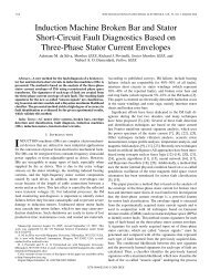
Fig. 6. Experimentally based results of the absolute value of Re(⃗i s (t)) in<br />
amperes versus angle δ(t) ≠ ⃗ i s (t) − ̸ ⃗v s (t) in degrees for the case of the<br />
5-hp inducti<strong>on</strong> motor under a healthy c<strong>on</strong>diti<strong>on</strong>.<br />
Fig. 5.<br />
Schematic representati<strong>on</strong> of a tapped inducti<strong>on</strong> motor.<br />
As representative examples of the many tests performed <strong>on</strong><br />
the 2-hp and 5-hp inducti<strong>on</strong> motors in the laboratory, the pendulous<br />
oscillati<strong>on</strong>s of the 5-hp inducti<strong>on</strong> motor in a polar coordinate<br />
plot are shown in Figs. 6 and 7 with corresp<strong>on</strong>ding enlargements<br />
(zooms) in Figs. 8 and 9, respectively, for a healthy and a<br />
12 turns (5%) fault. The short circuit was through a 1-Ω resistor,<br />
r f =1Ω. Again, the range of the pendulous oscillati<strong>on</strong>, the<br />
so-called swing angle ∆δ, is shown for the above-menti<strong>on</strong>ed<br />
cases of Figs. 6 and 7 in an enlarged fashi<strong>on</strong> in Figs. 8 and 9,<br />
respectively. As <strong>on</strong>e can see in Fig. 9, an interturn fault generates<br />
an unfilled-petal shape with a slight degree of curvature.<br />
This curvature is due to the existence of the resistor r f in the<br />
circuit shown in Fig. 5, which is used to restrict the shorted<br />
loop current to an immune (safe) level of current that does <strong>no</strong>t<br />
cause permanent coil damage. The amplitude of the maximum<br />
thickness of the petal shape caused by the swing angle is used<br />
here as the interturn fault signature or index.<br />
The functi<strong>on</strong>al block diagram of an <strong>on</strong>-line interturn fault<br />
diag<strong>no</strong>sis using the swing angle, ∆δ, is depicted in Fig. 10. In<br />
this block diagram, the motor terminal currents and <strong>vol</strong>tages are<br />
measured through current and <strong>vol</strong>tage sensors and the outputs<br />
are digitized using an analog-to-digital (A/D) c<strong>on</strong>verter. The output<br />
signals of the A/D c<strong>on</strong>verter are filtered by a band pass filter<br />
(BPF), while the output signals of the BPF are further sampled<br />
(collected) throughout a period equal to the period of the power<br />
supply frequency; see Fig. 10. For each set of collected data<br />
Fig. 7. Experimentally based results of the absolute value of Re(⃗i s (t)) in<br />
amperes versus angle δ(t) ≠ ⃗ i s (t) − ̸ ⃗v s (t) in degrees for the case of the<br />
5-hp inducti<strong>on</strong> motor under a faulty c<strong>on</strong>diti<strong>on</strong> having 12 (5%) shorted turns,<br />
(shorted through 1-Ω resistor.)<br />
Fig. 8. Enlarged dotted-frame porti<strong>on</strong> of Fig. 6, showing swing angle, ∆δ =<br />
max(∆δ(r) =δ max − δ min ), in the healthy situati<strong>on</strong>.