Crosshole Sonic Logging - Olson Instruments, Inc.
Crosshole Sonic Logging - Olson Instruments, Inc.
Crosshole Sonic Logging - Olson Instruments, Inc.

Create successful ePaper yourself
Turn your PDF publications into a flip-book with our unique Google optimized e-Paper software.
CSL Method<br />
N D E<br />
C ROSSHOLE S ONIC L OGGING<br />
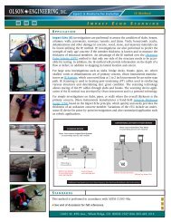
A PPLICATION<br />
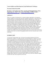
<strong>Olson</strong> Engineering is a pioneer in the instrumentation and use of CSL tests for<br />
checking the integrity of newly placed drilled shafts, seal footings, and slurry or<br />
diaphragm walls. The CSL test relies on propagation of ultrasonic waves between<br />
two or more access tubes to measure the velocity and signal strength of the propagated<br />
waves. The testing can be performed on any concrete foundation provided<br />
two or more access tubes or coreholes capable of holding water are present in the<br />
foundation. CSL can also be used to check the integrity of underwater concrete piers<br />
and foundations by strapping access tubes to the sides. <strong>Crosshole</strong> Tomography can<br />
be performed to image critical anomalies found in CSL tests as discussed below.<br />
A companion of the CSL test is the Singlehole <strong>Sonic</strong> <strong>Logging</strong> (SSL) test, which can be<br />
performed in one access tube or corehole to check the integrity of the concrete foundation<br />
around the tube in a fashion similar to Gamma-Gamma nuclear density tests.<br />
CSL tests are typically performed on concrete, particularly concrete drilled shafts.<br />
Other materials, which support transmission of ultrasonic waves, can be tested, such<br />
as slurry, rock, grout, water-saturated media, and cemented radioactive wastes.<br />
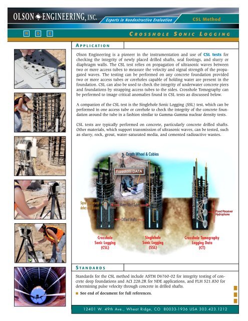
Depth Wheel & Cables<br />
Freedom DATA<br />
Signal goes around<br />
defect or is blocked<br />
Water Filled Tubes<br />
Drilled Shafts<br />
Travel Path<br />
Moving Source Hydrophone<br />
Fixed Receiver<br />
Hydrophone<br />
<strong>Crosshole</strong><br />
<strong>Sonic</strong> <strong>Logging</strong><br />
(CSL)<br />
Singlehole<br />
<strong>Sonic</strong> <strong>Logging</strong><br />
(SSL)<br />
<strong>Crosshole</strong> Tomography<br />
<strong>Logging</strong> Data<br />
(CT)<br />
S TANDARDS<br />
Standards for the CSL method include ASTM D6760-02 for integrity testing of concrete<br />
deep foundations and ACI 228.2R for NDE applications, and FLH 521.830 for<br />
determining pulse velocity through concrete in drilled shafts.<br />
■ See end of document for full references.<br />
12401 W. 49th Ave., Wheat Ridge, CO 80033-1936 USA 303.423.1212
CSL N D E<br />
GPR<br />
C ROSSHOLE S ONIC L OGGING<br />
F IELD<br />
I NVESTIGATION<br />
ACCESS<br />
Access tubes must be installed before the construction<br />
of the drilled shaft for quality assurance purposes,<br />
unless coreholes are to be drilled in a forensic case.<br />
PVC or black steel tubes (U.S. schedule 40) are typically<br />
used. The tubes are 1.5 (steel tubes only) to 2<br />
inches (38 to 50 mm) in diameter, and are typically<br />
tied to the inside of the rebar cage to ensure close to<br />
vertical positions of the tubes. The tubes must extend<br />
about 3 feet (1 m) above the top of the shaft to compensate<br />
for the water displaced by the source, receiver,<br />
and cables and to allow for easy access. Tubes must<br />
be bonded to the concrete for good test results. In<br />
order to minimize debonding of tubes, water should<br />
be added immediately prior to or after concrete placement<br />
and the tubes should not be mechanically disturbed.<br />
At least two tubes are needed to perform the CSL test. For good coverage of the test shaft,<br />
we recommend the following number of tubes be installed:<br />
SHAFT DIAMETER RECOMMENDED NUMBER OF TUBES TUBE SPACING<br />
D < 2.5 ft (0.75m) 2 minimum 180 Degree<br />
2.5 < D < 3.5 ft (1.0 m) 3 minimum 120 Degrees<br />
3.5 < D < 5.0 ft (1.5 m) 4 minimum 90 Degrees<br />
5.0 < D < 8.0 ft (2.5 m) 6 minimum 60 Degrees<br />
8.0 < D < 8 minimum 45 Degrees<br />
The concrete in the shaft should normally be<br />
allowed at least 1-2 days to cure to hardened concrete<br />
prior to testing. If PVC tubes are used, testing<br />
should be done within 10 days after the placement<br />
of concrete due to possible tube-concrete debonding.<br />
If steel tubes are used, the testing can be done<br />
within 45 days after concrete placement as the<br />
steel tubes bond better than PVC tubes over a<br />
longer time.<br />
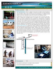
COLLECTION OF DATA<br />
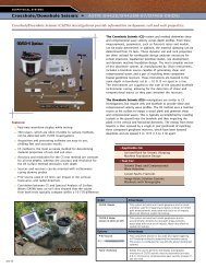
In a CSL test, the source is lowered to the bottom of<br />
one of the tubes and the receiver is lowered to the<br />
bottom of another tube. The source and receiver are<br />
hydrophones<br />
CSL-1 SYSTEM: <strong>Inc</strong>ludes components shown above.<br />
CSL-2 SYSTEM: <strong>Inc</strong>ludes components shown above with an<br />
additional hydrophone.<br />
pulled simultaneously to allow the horizontal<br />
ultrasonic pulse velocity to be measured. A depth<br />
wheel controls the resolution of the collected data.<br />
Typically, the source is excited every 0.2 ft (6 cm)<br />
vertically and a measurement is taken. The source<br />
and receiver are pulled to the top of each shaft, thus<br />
giving a complete assessment of the concrete quality<br />
between the two tubes. CSL tests are typically<br />
performed between all the perimeter tubes to check<br />
the perimeter of the shaft. Additional opposing<br />
diagonal CSL tests are also performed to check the<br />
integrity of the inner core of the shaft. If there are<br />
more than 4 tubes and an anomaly is identified,<br />
CSL tests may be performed of subdiagonal tube<br />
pairs to further define an anomaly. A pair of tubes<br />
can be logged and the results displayed in less than<br />
approximately 5 minutes. <strong>Olson</strong> Engineering uses<br />
the <strong>Olson</strong> <strong>Instruments</strong> Freedom Data PC with the<br />
<strong>Crosshole</strong> and Singlehole <strong>Sonic</strong> <strong>Logging</strong> System<br />
(CSL-1 & CSL-2) for collection and analysis of CSL<br />
or SSL data.<br />
[ Page 2 ]<br />
OLSON ENGINEERING, INC., 12401 W. 49th Ave., Wheat Ridge, CO 80033-1936 USA 303.423.1212
CSL N D E<br />
C ROSSHOLE S ONIC L OGGING<br />
D ATA<br />
R EDUCTION<br />
P ROCESSING T ECHNIQUES<br />
The collected data from CSL measurements<br />
between two tubes at all depths are saved in<br />
one file. The file is scanned to determine first<br />
wave arrival times and energy levels at all<br />
depths. A CSL log shows both the arrival time<br />
(or velocity) and signal energy plots vs. depth<br />
(see next page).<br />
I NTERPRETATION O F D ATA<br />
In uniform, good quality concrete, the travel<br />
time between vertical equi-distant tubes will be<br />
relatively constant and correspond to a reasonable<br />
concrete pulse velocity from the bottom to<br />
the top of the foundation. The CSL test will also<br />
produce records with good signal amplitude<br />
and energy in good quality concrete. Longer<br />
travel times and lower amplitude/energy<br />
signals indicate the presence of irregularities<br />
such as poor quality concrete, void, honeycomb<br />
and soil intrusions. In some severe defects, the<br />
signal may be completely lost.<br />
E FFECTIVENESS<br />
The access tubes must be installed prior to concrete<br />
placement to perform CSL tests. For existing shafts or<br />
other concrete members, coreholes or drill holes must<br />
be drilled to allow access for the source and receiver<br />
hydrophones. CSL is best used for quality assurance.<br />
Tubes must be bonded to the concrete for good test<br />
results. In order to minimize debonding of tubes,<br />
water should be added immediately prior to or after<br />
concrete placement and the tubes should not be<br />
mechanically disturbed.<br />
The CSL method is the most accurate quality assurance<br />
method for defect identification in drilled shafts.<br />
CSL testing provides assurance that the foundation<br />
concrete is sound and also hardened as velocity to<br />
the 4 th power is proportional to concrete strength.<br />
In areas where defects are identified in the CSL<br />
results, additional tests can be performed to better<br />
define the defect. The additional tests include angled<br />
CSL tests, Singlehole <strong>Sonic</strong> <strong>Logging</strong> (SSL) tests, and<br />
<strong>Crosshole</strong> Tomography (CT) analyses. Our CSL system<br />
is used to collect the tomography data. The data is<br />
subsequently analyzed to develop a velocity tomogram<br />
(an image) with better characterization of the<br />
defect in terms of its size and location. For forensic<br />
purposes, another test which can be used for condition<br />
evaluation is <strong>Sonic</strong> Echo/Impulse Response.<br />
CSL VS SE/IR CSL VS G AMMA-GAMMA<br />
One of the advantages of the CSL method over the<br />
surface <strong>Sonic</strong> Echo/Impulse Response method is<br />
that multiple defects can be identified in the same<br />
shaft using CSL, which may not be possible with<br />
the SE/IR method. In addition, the extent, nature,<br />
and the location of the defect can be determined<br />
with the CSL method as compared to only the<br />
depth of the defect from the SE/IR method. Finally,<br />
the CSL method is sensitive to smaller defects and<br />
yields more accurate depth information.<br />
When compared to Gamma-Gamma tests, the primary<br />
advantage of the CSL method is that CSL can locate<br />
defects that exist between tubes, which cannot be<br />
done with Gamma-Gamma tests. CSL testing is also<br />
much quicker, cheaper, and safer than Gamma-<br />
Gamma, and requires no special precautions which<br />
are required for the Gamma-Gamma tests. Also,<br />
Gamma-Gamma tests will falsely indicate sound<br />
concrete placement in terms of density when concrete<br />
is not cured if it is dense. The CSL test will indicate<br />
uncured or slow curing concrete as being a no<br />
signal to low velocity condition.<br />
OLSON ENGINEERING, INC., 12401 W. 49th Ave., Wheat Ridge, CO 80033-1936 USA 303.423.1212<br />
[ Page 3 ]
CSL CSL N N D D E E<br />
C ROSSHOLE S ONIC L OGGING<br />
E XAMPLE<br />
R ESULTS<br />
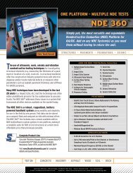
CSL LOG - PIER<br />
The image below shows a more minor defect at<br />
about 30 ft. The ultrasonic signals (time vs. voltage)<br />
show sound, major defect and minor defect results.<br />
CSL LOG - SOUND SHAFT<br />
The image to the right<br />
shows a typical CSL log for<br />
what is known as a sound<br />
shaft. A consistent signal<br />
arrival time and signal energy<br />
level can be seen for the<br />
entire tested length of the<br />
shaft.<br />
[ Page 4 ]<br />
OLSON ENGINEERING, INC., 12401 W. 49th Ave., Wheat Ridge, CO 80033-1936 USA 303.423.1212
CSL N D E<br />
C ROSSHOLE S ONIC L OGGING<br />
R EFERENCES<br />
Standards and<br />
Governmental Reports<br />
■ ACI 228.2R, “Nondestructive Test Methods for<br />
Evaluation of Concrete in Structures”, ACI<br />
Manual of Concrete Practice, Part 2,<br />
Construction Practices and Inspection,<br />
Pavements, ACI International.<br />
■ ASTM D6760-02, “Standard Test Method for<br />
Integrity Testing of Concrete Deep<br />
Foundations by Ultrasonic <strong>Crosshole</strong><br />
Testing”, Book of Standards Volume 04.09,<br />
ASTM International.<br />
■ FLH 521.830, “Standard Method for Determining<br />
Pulse Velocity Through Concrete in Drilled<br />
Shafts”, Federal Lands Highway Division,<br />
Federal Highway Administration.<br />
OLSON ENGINEERING P UBLICATIONS<br />
■ “<strong>Crosshole</strong> <strong>Sonic</strong> <strong>Logging</strong> and Tomographic<br />
Velocity Imaging of a New Drilled Shaft Bridge<br />
Foundation”, Larry D. <strong>Olson</strong>, P.E., David A.<br />
Hollema, Structural Materials Technology<br />
Topical Conference, Cincinnati, Ohio,<br />
September 10-13, 2002.<br />
■ “Drilled Shaft Defect Detection and Resolution”,<br />
Larry D. <strong>Olson</strong>, P.E., Association of Drilled Shafts<br />
Contractors Drilled Shaft Foundation Symposium,<br />
Austin, Texas, January 30, 1998.<br />
■ “NDT Diagnosis of Drilled Shaft Foundations”,<br />
Larry D. <strong>Olson</strong>, P.E., Marwan F. Aouad, Ph.D.,<br />
and Dennis A. Sack, Transportation Research<br />
Board, 77 th Annual Meeting, Washington, D.C.,<br />
January 11-15, 1998.<br />
■ “Quality Assurance of Drilled Shaft Foundations with<br />
Nondestructive Testing”, Larry D. <strong>Olson</strong>, Marshall<br />
Lew, Greg C. Phelps, K.N. Murthy, B.M. Ghadiali,<br />
Proceedings Federal Highway Administration<br />
Conference on Deep Foundations, Orlando,<br />
Florida, December 1994.<br />
■ “Nondestructive Testing of Deep Foundations with<br />
<strong>Sonic</strong> Methods”, Larry D. <strong>Olson</strong>, Clifford C.<br />
Wright, ASCE Geotechnical And Construction<br />
Divisions - Foundation Engineering Conference,<br />
Northwestern University, Evanston, Illinois,<br />
June 1989.<br />
OLSON ENGINEERING, INC.<br />
Corporate Headquarters:<br />
12401 W. 49th Ave.<br />
Wheat Ridge, CO 80033-1936 USA<br />
Phone: 303.423.1212<br />
Fax: 303.423.6071<br />
■ ldolson@olsonengineering.com<br />
www.olsonengineering.com<br />
www.olsoninstruments.com