TDA8947J anfi devresi (2x25w 1x50w) - 320Volt
TDA8947J anfi devresi (2x25w 1x50w) - 320Volt
TDA8947J anfi devresi (2x25w 1x50w) - 320Volt

Create successful ePaper yourself
Turn your PDF publications into a flip-book with our unique Google optimized e-Paper software.
Philips Semiconductors<br />
<strong>TDA8947J</strong><br />
4-channel audio amplifier<br />
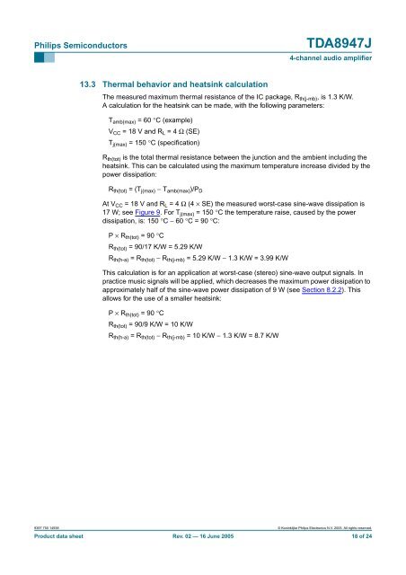
13.3 Thermal behavior and heatsink calculation<br />
The measured maximum thermal resistance of the IC package, R th(j-mb) , is 1.3 K/W.<br />
A calculation for the heatsink can be made, with the following parameters:<br />
T amb(max) =60°C (example)<br />
V CC = 18 V and R L =4Ω (SE)<br />
T j(max) = 150 °C (specification)<br />
R th(tot) is the total thermal resistance between the junction and the ambient including the<br />
heatsink. This can be calculated using the maximum temperature increase divided by the<br />
power dissipation:<br />
R th(tot) =(T j(max) − T amb(max) )/P D<br />
At V CC = 18 V and R L =4Ω (4 × SE) the measured worst-case sine-wave dissipation is<br />
17 W; see Figure 9. For T j(max) = 150 °C the temperature raise, caused by the power<br />
dissipation, is: 150 °C − 60 °C =90°C:<br />
P × R th(tot) =90°C<br />
R th(tot) = 90/17 K/W = 5.29 K/W<br />
R th(h-a) =R th(tot) − R th(j-mb) = 5.29 K/W − 1.3 K/W = 3.99 K/W<br />
This calculation is for an application at worst-case (stereo) sine-wave output signals. In<br />
practice music signals will be applied, which decreases the maximum power dissipation to<br />
approximately half of the sine-wave power dissipation of 9 W (see Section 8.2.2). This<br />
allows for the use of a smaller heatsink:<br />
P × R th(tot) =90°C<br />
R th(tot) = 90/9 K/W = 10 K/W<br />
R th(h-a) =R th(tot) − R th(j-mb) = 10 K/W − 1.3 K/W = 8.7 K/W<br />
9397 750 14938 © Koninklijke Philips Electronics N.V. 2005. All rights reserved.<br />
Product data sheet Rev. 02 — 16 June 2005 18 of 24