APPLICATION NOTE: Laser Triangulation Sensors - MTI Instruments ...
APPLICATION NOTE: Laser Triangulation Sensors - MTI Instruments ...
APPLICATION NOTE: Laser Triangulation Sensors - MTI Instruments ...

You also want an ePaper? Increase the reach of your titles
YUMPU automatically turns print PDFs into web optimized ePapers that Google loves.
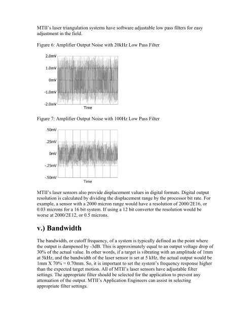
<strong>MTI</strong>I’s laser triangulation systems have software adjustable low pass filters for easy<br />
adjustment in the field.<br />
Figure 6: Amplifier Output Noise with 20kHz Low Pass Filter<br />
Figure 7: Amplifier Output Noise with 100Hz Low Pass Filter<br />
<strong>MTI</strong>I’s laser sensors also provide displacement values in digital formats. Digital output<br />
resolution is calculated by dividing the displacement range by the processor bit rate. For<br />
example, a sensor with a 2000 micron range would have a resolution of 2000/2E16, or<br />
0.03 microns for a 16 bit system. If using a 12 bit converter the resolution would be<br />
worse at 2000/2E12, or 0.5 microns.<br />
v.) Bandwidth<br />
The bandwidth, or cutoff frequency, of a system is typically defined as the point where<br />
the output is dampened by -3dB. This is approximately equal to an output voltage drop of<br />
30% of the actual value. In other words, if a target is vibrating with an amplitude of 1mm<br />
at 5kHz, and the bandwidth of the laser sensor is set at 5 kHz, the actual output would be<br />
1mm X 70% = 0.70mm. So, it is important to set the system’s frequency response higher<br />
than the expected target motion. All of <strong>MTI</strong>I’s laser sensors have adjustable filter<br />
settings. The appropriate filter should be selected for the application to prevent any<br />
attenuation of the output. <strong>MTI</strong>I’s Application Engineers can assist in selecting<br />
appropriate filter settings.