APPLICATION NOTE: Laser Triangulation Sensors - MTI Instruments ...
APPLICATION NOTE: Laser Triangulation Sensors - MTI Instruments ...
APPLICATION NOTE: Laser Triangulation Sensors - MTI Instruments ...

Create successful ePaper yourself
Turn your PDF publications into a flip-book with our unique Google optimized e-Paper software.
<strong>Laser</strong> <strong>Triangulation</strong> <strong>Sensors</strong><br />
1) Introduction<br />
<strong>APPLICATION</strong> <strong>NOTE</strong>:<br />
<strong>Laser</strong> triangulation sensors can be divided into two categories based upon their<br />
performance and intended use. High resolution lasers are typically used in displacement<br />
and position monitoring applications where high accuracy, stability and low temperature<br />
drift are required. Quite frequently these sensors are used in process monitoring and<br />
closed-loop feedback control systems. Proximity type laser triangulation sensors are<br />
much less expensive and are typically used to detect the presence of a part, or used in<br />
counting applications. The following paper describes characteristics of high resolution<br />
systems, their operating principle, advantages/disadvantages and how to successfully<br />
apply them.<br />
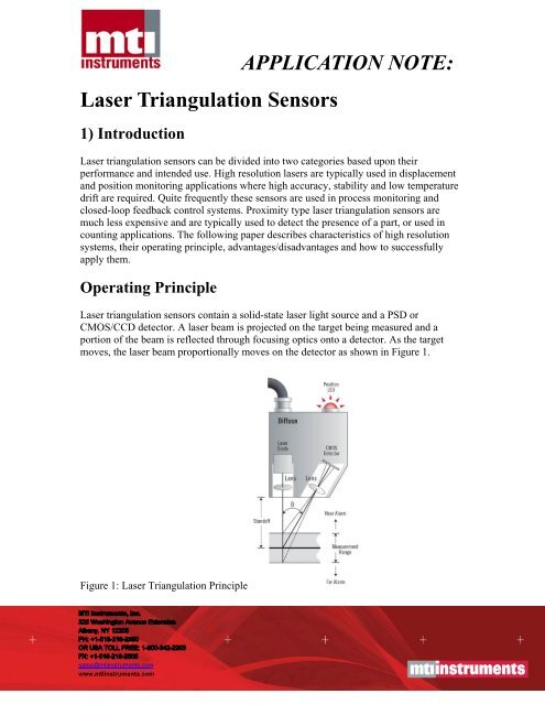
Operating Principle<br />
<strong>Laser</strong> triangulation sensors contain a solid-state laser light source and a PSD or<br />
CMOS/CCD detector. A laser beam is projected on the target being measured and a<br />
portion of the beam is reflected through focusing optics onto a detector. As the target<br />
moves, the laser beam proportionally moves on the detector as shown in Figure 1.<br />
Figure 1: <strong>Laser</strong> <strong>Triangulation</strong> Principle<br />
sales@mtiinstruments.com<br />
www.mtiinstruments.com
The signal from the detector is used to determine the relative distance to the target. This<br />
information is then typically available through an analog output, a digital (binary)<br />
interface or a digital display for processing.<br />
CMOS and CCD type sensors detect the peak distribution of light quantity on a sensor<br />
pixel array to identify target position, whereas, PSD type sensors calculate the beam<br />
centroid based upon the entire reflected spot on an array. Because of this, PSD type<br />
sensors are more susceptible to spurious reflections from changing surface conditions,<br />
which can reduce their accuracy. However, when measuring to ideal matte finishes or<br />
specular targets their resolution is unmatched. CCD and CMOS systems are typically<br />
more accurate over a wider variety of surfaces because only the highest charged pixels<br />
from the reflected beam are used to calculate position. The lower charged pixels are<br />
usually energized by unwanted reflections from changing optical properties of the surface<br />
being measured and can easily be ignored during signal processing. This allows them to<br />
be used in a wider variety of applications. Figure 2 show the signal distribution difference<br />
between CMOS and PSD technology, highlighting the potential accuracy problem<br />
associated with PSD type sensors.<br />
Figure 2: Potential Errors Induced by PSD Type <strong>Laser</strong> Sensor<br />
<strong>Laser</strong> triangulation sensors can also be used on highly reflective or mirror surfaces,<br />
commonly referred to as specular. With these surfaces the typical triangulation sensor, as<br />
shown in Figure 1, can’t be used because the laser light would bounce directly back into<br />
itself. For these cases it is necessary to direct the beam to the target at an angle. The beam<br />
will reflect from the target at an equal but opposite angle and focus onto the detector.<br />
<strong>MTI</strong>I manufactures laser heads specifically designed for specular surfaces or any of our<br />
lasers can be mounted at an angle and operated in the “specular mode” if necessary.<br />
Figure 3 shows the operating principle of a specular laser head.
Figure 3: Specular <strong>Laser</strong> <strong>Triangulation</strong> Principle<br />
2) Characteristics of <strong>Laser</strong> <strong>Sensors</strong><br />
i.) Non Contact<br />
<strong>Laser</strong> displacement sensors are non contact by design. That is, they are able to precisely<br />
measure the position or displacement of an object without touching it. Because of this the<br />
object being measured will not be distorted or damaged and target motions will not be<br />
dampened. Additionally, they can measure high frequency motions because no part of the<br />
sensor needs to stay in contact with the object, making them ideal for vibration<br />
measurements or high speed production line applications.<br />
ii.) Range/Standoff Distance<br />
As shown in Figure 1, laser triangulation systems have an ideal operating point which is<br />
sometimes referred to as the standoff distance. At this point the laser is at its sharpest<br />
focal point and the reflected spot is in the center of the detector. As the target moves the<br />
spot will move toward the ends of the detector allowing for measurements over a specific<br />
range. Both the range and standoff of a sensor are determined by its optical design.<br />
Optimal performance is obtained at the standoff distance because the spot is smallest at<br />
its focal point and highly concentrated on the detector. Detection algorithms correct for
any inaccuracies caused when operating slightly out of focus and most manufacturers<br />
specify performance over the complete measurement range.<br />
For a given length detector a smaller acceptance angle offers a larger measurement range<br />
and operating distance. A larger angle provides the opposite, however, higher sensitivity<br />
can be obtained because of optical leveraging. Figure 4 is a simplified diagram that<br />
visualizes the difference between two different acceptance angle sensors.<br />
Figure 4: <strong>Laser</strong> Acceptance Angle Dictates the Sensitivity and Measurement Range<br />
iii.) Sensitivity<br />
In measurement systems sensitivity is usually defined by how much displacement occurs<br />
per unit of measurement, typically expressed in microns/milli-volt. The “higher” the<br />
sensitivity (actually the smaller the number) the better in most cases because greater<br />
resolution may be obtained. To achieve the highest sensitivity it is desired to have the<br />
laser beam traverse across the complete detector length over the application measurement
ange. Figure 5 shows the output of two sensors with different sensitivities. Please note<br />
that the slope of each curve represents the respective sensitivity factor with Curve A<br />
being twice as sensitive.<br />
Figure 5: Sensitivity is Determined by the Slope of the Sensor Output Response<br />
iv.) Resolution<br />
The resolution of a displacement sensor is defined as the smallest amount of distance<br />
change that can be reliably measured. When properly designed, laser triangulation<br />
sensors offer extremely high resolution and stability, often approaching that of expensive<br />
and complex laser interferometer systems. Because of their ability to detect such small<br />
motions they have been successfully used in many demanding, high-precision<br />
measurement applications.<br />
The primary factor in determining resolution is the system’s electrical noise. If the<br />
distance between the sensor and target is constant, the output will still fluctuate slightly<br />
due to the “white” noise of the system. It is assumed that, without external signal<br />
processing, one cannot detect a shift in the output of less than the random noise of the<br />
instrument. Because of this most resolution values are presented based on the peak-topeak<br />
value of noise and can be represented by the following formula:<br />
Resolution = Sensitivity X Noise<br />
From the formula you can see that for a fixed sensitivity the resolution is solely<br />
dependent upon the noise of the system. The lower the noise the better the resolution!<br />
It is important to note that some manufacturers specify resolution based on peak or rms<br />
noise, resulting in claims that are 2x and 6x respectively better than peak-to-peak.<br />
Although an acceptable method, it is somewhat misleading as most users do not have the<br />
ability to decipher voltages changes less than the peak-to-peak noise value.<br />
The amount of noise depends on the system bandwidth. This is because noise is generally<br />
randomly distributed over a wide range of frequencies and limiting the bandwidth with<br />
filtering will remove some unwanted higher frequency fluctuations. Figures 6 and 7 show<br />
the difference in the output of two identical systems with different low pass filters. All of
<strong>MTI</strong>I’s laser triangulation systems have software adjustable low pass filters for easy<br />
adjustment in the field.<br />
Figure 6: Amplifier Output Noise with 20kHz Low Pass Filter<br />
Figure 7: Amplifier Output Noise with 100Hz Low Pass Filter<br />
<strong>MTI</strong>I’s laser sensors also provide displacement values in digital formats. Digital output<br />
resolution is calculated by dividing the displacement range by the processor bit rate. For<br />
example, a sensor with a 2000 micron range would have a resolution of 2000/2E16, or<br />
0.03 microns for a 16 bit system. If using a 12 bit converter the resolution would be<br />
worse at 2000/2E12, or 0.5 microns.<br />
v.) Bandwidth<br />
The bandwidth, or cutoff frequency, of a system is typically defined as the point where<br />
the output is dampened by -3dB. This is approximately equal to an output voltage drop of<br />
30% of the actual value. In other words, if a target is vibrating with an amplitude of 1mm<br />
at 5kHz, and the bandwidth of the laser sensor is set at 5 kHz, the actual output would be<br />
1mm X 70% = 0.70mm. So, it is important to set the system’s frequency response higher<br />
than the expected target motion. All of <strong>MTI</strong>I’s laser sensors have adjustable filter<br />
settings. The appropriate filter should be selected for the application to prevent any<br />
attenuation of the output. <strong>MTI</strong>I’s Application Engineers can assist in selecting<br />
appropriate filter settings.
vi.) Spatial Resolution<br />
When taking measurements, laser sensors provide a distance approximately equal to the<br />
average surface location within the laser spot. They are not capable of accurately<br />
detecting the position of features smaller than the size of the spot, however, they can<br />
repeatably measure to rough surfaces. Because of this the laser spot should always be<br />
approximately 25% smaller than the smallest feature you are trying to measure. Smaller<br />
spots can distinguish smaller features on an object.<br />
vii.) Linearity<br />
In an ideal world the output from any sensor would be perfectly linear and not deviate<br />
from a straight line at any point. However, in reality there will be slight deviations from<br />
this line which define the system linearity. Typically, linearity is specified as a<br />
percentage of the Full Scale Measurement Range (FSR). During calibration the output<br />
from the laser head is compared to the output of a highly precise standard and differences<br />
are noted. These differences are automatically corrected for; through the use of look up<br />
tables. <strong>MTI</strong>I’s Microtrak II laser sensors offer the highest linearity available today. Most<br />
systems exceed +/-0.05% FSR with some achieving +/-0.01% or better.<br />
Accuracy is a function of linearity, resolution, temperature stability and drift, with<br />
linearity being the majority contributor. Fortunately, the linear response of <strong>MTI</strong>I’s<br />
sensors is very repeatable. Calibration reports provide data that can be used to correct<br />
additionally for the non-linearity of a system with inexpensive computers and correction<br />
software, resulting in improved accuracy if needed.<br />
3) Applying <strong>Laser</strong> <strong>Sensors</strong><br />
i.) Material and Finish<br />
In Section 1 we briefly mentioned the difference between a specular and diffuse laser<br />
head. When applying a laser sensor it is first necessary to determine the surface<br />
reflectivity. A consistent matte finish is desirable for best performance when using<br />
diffuse heads. If a highly polished or mirror finish will be used it is strongly<br />
recommended to use a specular laser head.<br />
ii.) Target Shape<br />
For ideal performance the target should be positioned normal (90 degrees) to the laser<br />
head to prevent tilt errors. The influence from tilt will be dependent on the surface<br />
reflective properties. An ideally diffuse target will allow proper operation on surfaces<br />
tilted 30 degrees or more from normal. However, a mirror target will produce errors if the<br />
tilt changes by as little as 1 degree. Care should be taken during fixture design and<br />
operation to minimize any target tilt.<br />
<strong>Laser</strong> sensors can also be used to measure curved targets. For best results the beam<br />
should be positioned facing directly toward the center of curvature. This will virtually<br />
eliminate any “tilt” seen by the laser. In addition, the orientation of the head should be
such that the curved surface does not skew the laser triangulation angle. Figure 8 shows<br />
the proper orientation for a system to reduce tilt effects.<br />
Figure 8: Note how the <strong>Laser</strong> Beam may be Deflected by Target Shape<br />
Care should also be taken to ensure the laser return light is not blocked by some feature<br />
on the target being measured. Figure 9 shows the right and wrong way to orientate a laser<br />
sensor.<br />
Figure 9: Note how the <strong>Laser</strong> Beam may be Obstructed by Target Features
iii.) Environmental Conditions<br />
Because laser triangulation systems are optical type sensors it is important to keep the<br />
optical path clean and free from obstructions or foreign materials. Dirt, dust and smoke<br />
can affect the measurement results or even render sensors completely useless. Care<br />
should be taken to eliminate such contamination and clean air purge systems should be<br />
used when required. If this type of system is not possible it is important to regularly clean<br />
the outer lenses to avoid problems.<br />
The most common environmental problem that can affect the accuracy of a laser sensor is<br />
temperature. Not only do the electronics exhibit temperature drift, but also expansion and<br />
contraction of mechanical components and fixturing can physically change the sensor<br />
gap. All of <strong>MTI</strong>I’s Microtrak II sensors have a temperature stability of less than +/-0.05%<br />
of the full scale measurement range over a temperature change of 0 to 40ºC.<br />
iv.) Fixturing<br />
It is important that the fixture holding a laser triangulation sensor is stable. As mentioned<br />
above, temperature changes can cause expansion and contraction, resulting in a distance<br />
change to the target. Fixtures should be made of the appropriate material to minimize this<br />
effect. The fixture supports should also be as short as possible and long cantilevers<br />
should be avoided to minimize not only temperature issues but to also reduce vibration.
<strong>MTI</strong>I’s laser sensors have through holes that can be used to mount and secure the laser<br />
heads. Fixtures should be made to match the location of these holes and maintain the<br />
laser head perpendicular to the target of interest.<br />
v.) Synchronization<br />
When making differential thickness measurements with 2 laser heads it is important to<br />
take and process measurements from both heads at the exact same time. This is to<br />
eliminate the effects due to vibration. If the target is moving, and measurements are taken<br />
at slightly different times, the processed results may report a slightly thinner or thicker<br />
target. <strong>MTI</strong>I’s Microtrak II line of laser sensors have provisions to synchronize heads<br />
eliminating this problem.<br />
4) Advantages and Disadvantages<br />
i.) Advantages<br />
As with any sensing technology, laser systems have both advantages and disadvantages.<br />
Perhaps their greatest attribute is their ability to resolve measurements below one micron<br />
at a fraction of the cost of other high performance technologies. In addition, their<br />
measurement range is large allowing them to fulfill a variety of application requirements.<br />
The large operating distance provides sufficient standoff to reduce possible damage from<br />
contacting the moving target.<br />
ii.) Disdvantages<br />
As mentioned above, laser sensors should be kept clean. Dirt or other foreign debris can<br />
affect accuracy so frequent cleaning may be required. Because laser heads have sensitive<br />
electronic components their operating temperature is limited and vacuum installations are<br />
not recommended without external cooling.<br />
5) Applications<br />
i.) Position Sensing<br />
General positioning is probably the most common application for laser sensors. Their<br />
fast, highly linear response makes them ideally suited to be applied in both static and<br />
active feedback positioning applications. Large operating distance and measurement<br />
range provides the flexibility for process and quality control monitoring. Typical<br />
applications include:<br />
• Pavement and concrete road profiling<br />
• Railroad track alignment<br />
• Robot location<br />
• Welding head position
Figure 10: Lead Position and Pitch on Integrated Circuits<br />
Figure 11: Closed Loop Control of Robotic and Positioning Systems<br />
ii.) Dynamic Measurements<br />
Non-contact sensors are ideal for measuring moving targets because they have high<br />
frequency response and do not dampen target motions by adding mass. <strong>MTI</strong>I’s laser<br />
sensors are designed with a 40 kHz sampling frequency and a true 20 kHz frequency<br />
response, making them ideal for high speed applications such as:<br />
• Spindle runout analysis<br />
• Piezoelectric characterization<br />
• Ultrasonic vibration measurements<br />
• In-line process monitoring
Figure 12: Vacuum Seal Integrity for Canning Industry<br />
Figure 13: Surface Profile of a Wide Variety of Materials<br />
iii.) Thickness and Dimensional Measurements<br />
On-line production thickness measurements have conventionally been made using direct<br />
contact type measurement systems. <strong>Sensors</strong>, such as LVDT’s, are positioned above and<br />
below the material being measured to track surface position. The sensor outputs are<br />
combined through software or a summing device and thickness is determined.<br />
Unfortunately, contact type methods cause measurement problems. Not only can the<br />
material being measured be damaged but sensor wear also occurs. In addition, contact<br />
sensors are slow and may not properly track targets that may move or vibrate, making<br />
these applications ideal for <strong>MTI</strong>I’s laser systems.<br />
Single sided thickness measurements are possible if one side of the material can be held<br />
constant against a fixed reference plane, however, for best results, two sided<br />
measurements are preferred. This is because a two sided approach eliminates any errors<br />
that might be introduced from the material moving or vibrating. <strong>MTI</strong>I’s two sensor<br />
approach synchronizes the data sampling for both sensors which ensures a correct
thickness reading. This type of system provides both analog (0-10V), (4-20 ma) and<br />
digital outputs (RS-485 binary format). Either can be used to provide thickness results,<br />
but analog is the preferred choice if high frequency (>100Hz) thickness is required.<br />
Successful applications include:<br />
• Process monitoring of wood thickness<br />
• Quality control during concrete block manufacturing<br />
• Separation distance between rollers<br />
• Brake rotor thickness<br />
Figure 14: Sheet and Web Thickness<br />
<strong>MTI</strong> <strong>Instruments</strong> Inc.<br />
325 Washington Avenue Extension<br />
Albany, NY 12205-5505 USA<br />
Phone: 518-218-2550<br />
Toll Free (US): 800-342-2203<br />
Fax: 518-218-2506<br />
E-mail: sales@mtiinstruments.com