Planet Hunter - Exoplanet Exploration Program - NASA
Planet Hunter - Exoplanet Exploration Program - NASA
Planet Hunter - Exoplanet Exploration Program - NASA
You also want an ePaper? Increase the reach of your titles
YUMPU automatically turns print PDFs into web optimized ePapers that Google loves.
PLANET HUNTER<br />
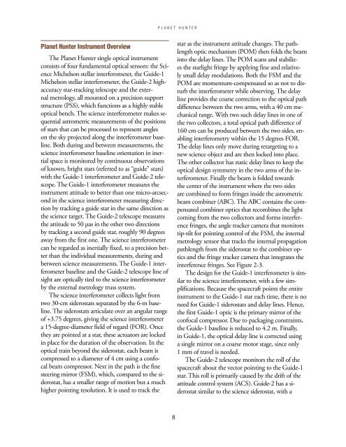
<strong>Planet</strong> <strong>Hunter</strong> Instrument Overview<br />
The <strong>Planet</strong> <strong>Hunter</strong> single optical instrument<br />
consists of four fundamental optical sensors: the Science<br />
Michelson stellar interferometer, the Guide-1<br />
Michelson stellar interferometer, the Guide-2 highaccuracy<br />
star-tracking telescope and the external<br />
metrology, all mounted on a precision support<br />
structure (PSS), which functions as a highly stable<br />
optical bench. The science interferometer makes sequential<br />
astrometric measurements of the positions<br />
of stars that can be processed to represent angles<br />
on the sky projected along the interferometer baseline.<br />
Both during and between measurements, the<br />
science interferometer baseline orientation in inertial<br />
space is monitored by continuous observations<br />
of known, bright stars (referred to as “guide” stars)<br />
with the Guide-1 interferometer and Guide-2 telescope.<br />
The Guide-1 interferometer measures the<br />
instrument attitude to better than one micro-arcsecond<br />
in the science interferometer measuring direction<br />
by tracking a guide star in the same direction as<br />
the science target. The Guide-2 telescope measures<br />
the attitude to 50 µas in the other two directions<br />
by tracking a second guide star, roughly 90 degrees<br />
away from the first one. The science interferometer<br />
can be regarded as inertially fixed, to a precision better<br />
than the individual measurements, during and<br />
between science measurements. The Guide-1 interferometer<br />
baseline and the Guide-2 telescope line of<br />
sight are optically tied to the science interferometer<br />
by the external metrology truss system.<br />
The science interferometer collects light from<br />
two 30-cm siderostats separated by the 6-m baseline.<br />
The siderostats articulate over an angular range<br />
of +3.75 degrees, giving the science interferometer<br />
a 15-degree-diameter field of regard (FOR). Once<br />
they are pointed at a star, these actuators are locked<br />
in place for the duration of the observation. In the<br />
optical train beyond the siderostat, each beam is<br />
compressed to a diameter of 4 cm using a confocal<br />
beam compressor. Next in the path is the fine<br />
steering mirror (FSM), which, compared to the siderostat,<br />
has a smaller range of motion but a much<br />
higher pointing resolution. It is used to track the<br />
star as the instrument attitude changes. The pathlength<br />
optic mechanism (POM) then folds the beam<br />
into the delay lines. The POM scans and stabilizes<br />
the starlight fringe by applying fine and relatively<br />
small delay modulations. Both the FSM and the<br />
POM are momentum-compensated so as not to disturb<br />
the interferometer while observing. The delay<br />
line provides the coarse correction to the optical path<br />
difference between the two arms, with a 40 cm mechanical<br />
range. With two such delay lines in one of<br />
the two collectors, a total optical path difference of<br />
160 cm can be produced between the two sides, enabling<br />
interferometry within the 15 degrees FOR.<br />
The delay lines only move during retargeting to a<br />
new science object and are then locked into place.<br />
The other collector has static delay lines to keep the<br />
optical design symmetry in the two arms of the interferometer.<br />
Finally the beam is folded towards<br />
the center of the instrument where the two sides<br />
are combined to form fringes inside the astrometric<br />
beam combiner (ABC). The ABC contains the compensated<br />
combiner optics that recombines the light<br />
coming from the two collectors and forms interference<br />
fringes, the angle tracker camera that monitors<br />
tip-tilt for pointing control of the FSM, the internal<br />
metrology sensor that tracks the internal propagation<br />
pathlength from the siderostat to the combiner optics<br />
and the fringe tracker camera that integrates the<br />
interference fringes. See Figure 2-3.<br />
The design for the Guide-1 interferometer is similar<br />
to the science interferometer, with a few simplifications.<br />
Because the spacecraft points the entire<br />
instrument to the Guide-1 star each time, there is no<br />
need for Guide-1 siderostats and delay lines. Hence,<br />
the first Guide-1 optic is the primary mirror of the<br />
confocal compressor. Due to packaging constraints,<br />
the Guide-1 baseline is reduced to 4.2 m. Finally,<br />
in Guide-1, the optical delay line is corrected using<br />
a single mirror on a coarse motor stage, since only<br />
1 mm of travel is needed.<br />
The Guide-2 telescope monitors the roll of the<br />
spacecraft about the vector pointing to the Guide-1<br />
star. This roll is primarily caused by the drift of the<br />
attitude control system (ACS). Guide-2 has a siderostat<br />
similar to the science siderostat, with a<br />
8


