

Lyot Coronagraphs with Band-Limited Masks - Exoplanet ...
Lyot Coronagraphs with Band-Limited Masks - Exoplanet ...
Lyot Coronagraphs with Band-Limited Masks - Exoplanet ...

You also want an ePaper? Increase the reach of your titles
YUMPU automatically turns print PDFs into web optimized ePapers that Google loves.
<strong>Lyot</strong> <strong>Coronagraphs</strong> <strong>with</strong> <strong>Band</strong>-<strong>Limited</strong> <strong>Masks</strong> <strong>Exoplanet</strong> Detection <strong>with</strong> <strong>Coronagraphs</strong> 2006<br />
<strong>Lyot</strong> <strong>Coronagraphs</strong> <strong>with</strong> <strong>Band</strong>-<strong>Limited</strong> <strong>Masks</strong><br />
Brian Kern<br />
Jet Propulsion Laboratory, California Institute of Technology<br />
INTRODUCTION<br />
<strong>Band</strong>-limited masks in <strong>Lyot</strong> coronagraphs have received more theoretical and experimental attention than any<br />
other coronagraph design under consideration for TPF-C, and 8 th -order band-limited masks were the assumed<br />
architecture for Flight Baseline 1. The best contrast achieved to date has been <strong>with</strong> band-limited masks, on JPL’s<br />
High Contrast Imaging Testbed (HCIT) (see Trauger, these proceedings). This paper will attempt to illustrate the<br />
advantages and disadvantages of band-limited masks, compared to the other potential TPF-C coronagraph<br />
architectures; the primary disadvantage is modest throughput and point-spread function (PSF) width, the primary<br />
advantages are robustness to aberrations, mechanical simplicity, and maturity.<br />
INNER WORKING ANGLE AND THROUGHPUT<br />
<strong>Band</strong>-limited masks for coronagraphs have been proposed in Kuchner & Traub (2002) and Kuchner, Crepp &<br />
Ge (2005). The fundamental feature of these coronagraphs is a mask that absorbs much of the on-axis light,<br />
diffracting the rest to an opaque <strong>Lyot</strong> stop. This gives zero on-axis transmission, <strong>with</strong> modest transmission offaxis.<br />
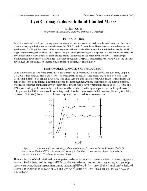
Most of the band-limited attention has gone to linear occulters, whose transmission is a function of only<br />
one spatial variable; coronagraphs <strong>with</strong> linear band-limited masks have typical transmissions of ~ 30–45% at 4<br />
λ/D, shown in Figure 1. Because the <strong>Lyot</strong> stop must be smaller than the system pupil, the resulting off-axis PSF<br />
is larger than the PSF incident on the occulting mask. It is this transmission and diffractive efficiency (a relative<br />
measure of PSF size) that determine the total exposure time needed for an observation.<br />
0.6<br />
0.5<br />
0.4<br />
T<br />
0.3<br />
0.2<br />
0.1<br />
0.0<br />
0 5 10 15 20<br />
x[λ/D]<br />
Figure 1: Transmission (T) versus image plane position (x) for sample linear 4 th -order (1-sinc 2 )<br />
mask (solid line) and 8 th -order m=1, l=3 mask (dashed line). Each mask is chosen to maximize<br />
transmission at 4 λ/D (shown as vertical line).<br />
The combination of mask width and <strong>Lyot</strong> stop size can be varied to optimize transmission at a given image plane<br />
location. Smaller inner working angles (IWAs) can be reached using narrower occulting masks, but <strong>Lyot</strong> stops<br />
become narrower, decreasing transmission and increasing PSF width. A 4 th -order (1-sinc 2 ) mask can be designed<br />
to give 0.45 transmission at 4 λ/D, or 0.16 at 2 λ/D. An 8 th -order m = 1, l = 3 mask can give 0.30 at 4 λ/D, or<br />
0.03 at 2 λ/D.<br />
142
<strong>Exoplanet</strong> Detection <strong>with</strong> <strong>Coronagraphs</strong> 2006<br />
<strong>Lyot</strong> <strong>Coronagraphs</strong> <strong>with</strong> <strong>Band</strong>-<strong>Limited</strong> <strong>Masks</strong><br />
Since the release of the TPF-C FB1 specifics, there has been a drive to reconsider smaller telescopes, and<br />
coronagraph architectures that accommodate smaller IWAs. As mentioned above, a 4 th -order mask operating at 2<br />
λ/D can give 0.16 transmission. However, other concerns arise when decreasing the IWA. One that has received<br />
little attention is the contrast degradation due to finite stellar size, shown graphically in Figure 2. Because stars<br />
appear as incoherently illuminated discs, the stellar limb passes through the coronagraph off-axis, and leaves<br />
residual light in the image plane. This effect is more troubling at smaller IWAs or <strong>with</strong> narrower masks (neither<br />
shown in Fig. 2). Already at 4 λ/D, a 4 th -order mask can observe only 66 of the TPF-C top 100 stars to a contrast<br />
of 10 -11 ; going to smaller IWAs decreases this number further. By contrast, the 8 th -order mask can observe all<br />
100 stars to 10 -11 , because it is less sensitive to light at very small off-axis angles. Other 4 th - and 8 th -order<br />
coronagraph architectures, such as the optical vortex or visible nuller, should show similar sensitivities to stellar<br />
size.<br />
M6 V<br />
F0 V<br />
TPF-C Stellar Size Sensitivity<br />
10<br />
-5<br />
A5 III<br />
B3 III<br />
O5 Iab<br />
Contrast at 4 λ<br />
max / D<br />
10<br />
-6<br />
10<br />
-7<br />
10<br />
-8<br />
10<br />
-9<br />
10<br />
-10<br />
10<br />
-11<br />
Detection<br />
Threshold<br />
Smallest TPF-C Top 100<br />
Median TPF-C Top 100<br />
4th-order<br />
Largest TPF-C Top 100<br />
8th-order<br />
12thorder<br />
R Doradus = 57 ± 5 mas<br />
10 10 -1 10 0 10 1 10 2<br />
Angular Diameter / mas<br />
Figure 2: Limiting contrast versus stellar angular diameter, for 4 th -order (circles), 8 th -order (triangles), and<br />
12 th -order (squares) masks, from Crepp (2006). Also shown are the 10 -11 assumed detection threshold<br />
(horizontal line), and the smallest, median, and largest diameters of the TPF-C top 100 stars (vertical lines).<br />
Representative spectral types are shown along the top, at their angular diameters at 10 pc. An 8 m telescope is<br />
assumed.<br />
REQUIREMENTS / SENSITIVITY TO ABERRATIONS<br />
The TPF-C dynamics error budget (Shaklan et al. 2005) and optical surface requirements (Shaklan, Green &<br />
Palacios 2006) establish the baseline requirements for 10 -10 contrast measurements. The dynamics error budget,<br />
in particular, assumes an 8 th -order linear occulter, which was chosen because its insensitivity to low-order<br />
aberrations (see Shaklan and Green 2005) allows a significant relaxation in pointing and rigid-body<br />
requirements. A sampling of the relative requirements of 4 th - and 8 th -order masks is shown in Table 1, taken<br />
from the TPF-C STDT. To first order, this table also represents the comparison between band-limited masks and<br />
other 4 th - and 8 th -order architectures, such as the optical vortex and visible nuller.<br />
143
<strong>Lyot</strong> <strong>Coronagraphs</strong> <strong>with</strong> <strong>Band</strong>-<strong>Limited</strong> <strong>Masks</strong> <strong>Exoplanet</strong> Detection <strong>with</strong> <strong>Coronagraphs</strong> 2006<br />
Table 1: Maximum allowed dynamic RMS wave front errors to maintain 10 -12 contrast per error<br />
term, for 4th- and 8 th -order masks, in units of 550 nm waves. The relaxation ratio is the ratio of<br />
the requirements for 4 th and 8 th -order masks, showing that 8 th order masks allow a significant<br />
(i.e., orders of magnitude) relaxation in pointing / stability requirements.<br />
Aberration<br />
8th<br />
order<br />
4th<br />
order relaxation ratio<br />
Tilt 4.3e-2 2.7e-3 16<br />
Focus 3.8e-3 2.9e-5 132<br />
Astigmatism 5.3e-3 4.0e-5 132<br />
Coma 1.0e-3 5.6e-5 185<br />
Trefoil 2.3e-3 1.7e-5 132<br />
Spherical 3.5e-5 4.9e-6 7.2<br />
Separate from the dynamic wavefront errors, elliptical polarization induced by reflection of flat wavefronts off<br />
curved mirror surfaces (or by reflection of a curved wavefront off flat mirror surfaces) results in low-order<br />
spatially varying phase differences between orthogonal polarizations. The resulting wavefront errors in<br />
orthogonal polarizations differ, and DM corrections cannot separately correct the two polarizations; corrections<br />
applied to one polarization will worsen the other. This has been characterized for TPF-C in Balasubramanian<br />
et al. (2005). Downstream from the primary mirror, two separate polarization channels can be constructed, each<br />
<strong>with</strong> its own coronagraph, to separately correct the two polarizations. This construction allows for independent<br />
correction of orthogonal polarizations, and so allows the two co-polarized wavefronts to be independently<br />
corrected; however, when observing an un- or partially-polarized thermal source, the cross-polarized wavefronts<br />
cannot be separately corrected (<strong>with</strong>out installing separate polarization channels upstream of the primary mirror).<br />
In all cases, the aberrations introduced between polarizations are low-order, and 8th-order masks are therefore<br />
much less sensitive to these terms than are 4th-order masks. The net result is that 4th-order coronagraphs require<br />
either separate polarization channels or specialized mirror coatings (that minimize the polarization signature) to<br />
achieve 10 -10 contrast, while 8th-order coronagraphs require neither. As <strong>with</strong> the dynamic requirements, the<br />
selection of an 8th-order architecture (whether band-limited mask or optical vortex) significantly relaxes the<br />
polarization requirements.<br />
The bandwidth of band-limited mask coronagraphs is limited by either occulting mask errors or the broadband<br />
behavior of wavefront correction. Any wavefront correction using DMs has a limited bandwidth, as considered<br />
in Shaklan, Green & Palacios (2006). In the absence of wavefront errors, there is no inherent bandwidth limit to<br />
band-limited masks. The masks themselves will be chromatic at some level, <strong>with</strong> both the modulus and phase of<br />
the complex amplitude transmission profile varying <strong>with</strong> wavelength. This will be discussed further in Sections 4<br />
and 5. But aside from the mask transmission, there is no aspect of these coronagraphs that imposes any<br />
additional bandwidth constraints beyond the need to make wavefront corrections using DMs.<br />
MODELING / MODEL VALIDATION<br />
Detailed optical broadband modeling, simulating the contrast performance of band-limited masks, has been done<br />
in four different contexts at JPL:<br />
• PROPER, an IDL-based library (Krist)<br />
• MACOS + proprietary Matlab code (Sidick)<br />
• Python proprietary code (Moody)<br />
• Fortran proprietary code (Hoppe)<br />
The Fortran models used by Dan Hoppe were generated specifically to explore the unusual waveguiding effects<br />
of metallic binary occulting masks (Kuchner and Spergel 2003), and incorporated a more complicated EM<br />
propagation analysis to address those issues. The other three models vary in the specifics of their optical<br />
propagation techniques (although all include full Fresnel propagation to all intermediate optics), specification of<br />
surface figure errors, and computational optimization. The full diffraction calculations performed by the models<br />
avoid the limitations present in semi-analytic approximations; for example, the derivation of optical surface<br />
144
<strong>Exoplanet</strong> Detection <strong>with</strong> <strong>Coronagraphs</strong> 2006<br />
<strong>Lyot</strong> <strong>Coronagraphs</strong> <strong>with</strong> <strong>Band</strong>-<strong>Limited</strong> <strong>Masks</strong><br />
requirements for TPF-C (Shaklan, Green & Palacios 2006; Shaklan & Green 2006) uses 2nd-order Taylor<br />
expansions to approximate wavefront behavior, an approximation that is avoided in these models.<br />
The most meaningful application of these models is in conjunction <strong>with</strong> the High Contrast Imaging Testbed<br />
(HCIT) at JPL. HCIT is a <strong>Lyot</strong> coronagraph <strong>with</strong> a DM for wavefront correction, enclosed in a vacuum chamber,<br />
currently using (but not restricted to) band-limited masks. The purpose of HCIT is to validate model predictions<br />
and demonstrate the key technologies required for TPF-C. The level of maturity of this model-to-experiment<br />
connection, and the depth of experience <strong>with</strong> band-limited masks, make band-limited masks stand apart from<br />
other coronagraph architectures.<br />
An excellent example of the interplay between modeling and experiment is the analysis of polarization<br />
properties of binary band-limited masks. These binary masks were constructed of aluminum on glass, <strong>with</strong> a<br />
variable transmission profile formed by varying the duty-cycle of a high-frequency (smaller than Fλ) on-off<br />
pattern (aluminized to bare glass), as shown in Figure 3. The anisotropic nature of the high-frequency structure<br />
of the mask causes different phase shifts for orthogonal linear polarizations, <strong>with</strong> the relative phase shift varying<br />
<strong>with</strong> transmission. This is tested by correcting one polarization, and measuring the contrast in the orthogonal<br />
polarization, as shown in Figure 4. The experiment clearly validates the prediction that the orthogonal<br />
polarization will have significantly worse contrast, above 10 -7 .<br />
Figure 3: Continuous and binary representation of 1-sinc 2 4 th -order band-limited mask. Left panel is<br />
measured transmission of continuous, analog band-limited mask, right panels are SEM images of continuous<br />
and stepwise varying binary masks. Black areas of the right panels are aluminized.<br />
Data<br />
Models<br />
Nulled<br />
polarization<br />
Orthogonal<br />
polarization<br />
< 10 -8<br />
> 10 -7<br />
Figure 4: Coronagraph image plane in binary mask polarization experiment and model. Each<br />
panel is the coronagraph image plane, <strong>with</strong> occulted source at the center, after creating a dark<br />
hole using a DM. Only one linear polarization was used for correction, and the contrast in the<br />
orthogonal polarization was measured. The character of the agreement <strong>with</strong> the model, that the<br />
contrast differed between polarizations by >10×, gives confidence that the binary mask modeling<br />
captured the pertinent physical effects.<br />
145
<strong>Lyot</strong> <strong>Coronagraphs</strong> <strong>with</strong> <strong>Band</strong>-<strong>Limited</strong> <strong>Masks</strong> <strong>Exoplanet</strong> Detection <strong>with</strong> <strong>Coronagraphs</strong> 2006<br />
A significant amount of modeling goes toward understanding the effects of imperfect mask materials, and<br />
identifying mitigation strategies. For example, the analog masks in use on HCIT are written on High Energy<br />
Beam Sensitive (HEBS) glass. An occulting mask is written on HEBS glass by exposing it 100 keV electrons,<br />
<strong>with</strong> the total electron dose varying <strong>with</strong> position to give the desired absorption pattern. The transmitted phase<br />
varies <strong>with</strong> the optical density (OD) written (i.e., phase as well as OD varies <strong>with</strong> electron exposure), and<br />
because the OD varies spatially, the transmitted phase has spatial structure. This is reported in Halverson et al.<br />
(2005), and shown in Figure 5. The complex-valued nature of the occulter transmission means that the patterns<br />
intended to be band-limited in the absence of varying phase, are not band-limited when written on HEBS. The<br />
optical consequence of this is that in the <strong>Lyot</strong> plane, where a band-limited mask in a perfect coronagraph would<br />
produce diffracted light only near the edge of the pupil image and no light inside the <strong>Lyot</strong> stop, some amount of<br />
light is distributed throughout the <strong>Lyot</strong> plane when the occulter is not band-limited. This extra light is not<br />
distributed uniformly, but is brightest near the edges of the pupil and fainter near the center of the pupil. A <strong>Lyot</strong><br />
stop <strong>with</strong> a smaller opening will reject more of this light. Wavefront correction can also redistribute this light, so<br />
that a dark hole can be created in the image plane. Predicting the ultimate contrast behavior using different <strong>Lyot</strong><br />
stop sizes and wavefront correction requires detailed modeling.<br />
A further complication arises in that the relationships<br />
of both OD and phase to electron exposure vary <strong>with</strong><br />
wavelength. An occulter written to provide the<br />
correct OD at one wavelength will have a different<br />
OD profile at another wavelength, as well as a<br />
different phase profile. The models employed here<br />
predict the ability of wavefront control to maintain<br />
good broadband contrast in the presence of these<br />
variations.<br />
MASK FABRICATION<br />
As described in Section 4 above, one of the<br />
challenges of mask fabrication is finding a material<br />
(or a combination of materials) that allows sufficient<br />
control of OD and phase as a function of wavelength,<br />
so that a mask may be close enough to band-limited<br />
to achieve a target contrast. Two technologies have<br />
been tested at a significant level in the context of<br />
TPF-C and HCIT. The first is binary masks (see<br />
Fig. 3), <strong>with</strong> alternating areas of opaque and<br />
transparent areas, having a duty cycle that determines<br />
effective transmission on diffraction-sized spatial<br />
scales. The second is HEBS glass exposed by<br />
Figure 5: Phase versus optical density of HEBS glass, at<br />
4 wavelengths, from Halverson et al. (2005). When an<br />
occulting mask is written to have a band-limited<br />
absorption profile, the resulting variations in<br />
transmitted phase cause the mask not to be band-limited.<br />
electron beams, to give a continuous analog absorption profile. Neither of these technologies are expected to<br />
deliver broadband (δλ/λ ~ 10% or wider) contrast at the 10 -10 level, based on detailed modeling (and supported<br />
by experiments on HCIT).<br />
Current mask investigations are exploring continuous analog metallic occulters as well as combined metallic and<br />
dielectric occulters. The modeling of these occulters, whose materials should be readily manufacturable,<br />
currently predict contrast values between 10 -10 and 10 -9 , for δλ/λ = 10%. Further improvements, to the 10 -10 level,<br />
are anticipated <strong>with</strong> additional investigations into metallic properties, currently underway.<br />
Tolerances on random occulting mask errors (or any other image-plane errors) have been calculated by Lay et al.<br />
(2005) for contrast levels appropriate to TPF-C. These requirements are consistent <strong>with</strong> the current limits of<br />
superpolished surfaces.<br />
146
<strong>Exoplanet</strong> Detection <strong>with</strong> <strong>Coronagraphs</strong> 2006<br />
<strong>Lyot</strong> <strong>Coronagraphs</strong> <strong>with</strong> <strong>Band</strong>-<strong>Limited</strong> <strong>Masks</strong><br />
DISCUSSION<br />
Relative to other coronagraph architectures, band-limited masks offer modest throughput, excellent robustness to<br />
dynamic aberrations, low optical complexity, and unrivaled experimental verification. The experimental<br />
verification, and the maturity of the models that accompany band-limited masks, make this approach relatively<br />
low-risk compared to other architectures, at their current state of development.<br />
The theoretical band-limited mask throughput is better than that of shaped pupils, similar to that of the visible<br />
nuller, and worse than those of optical vortices, phase-induced amplitude apodization, or external occulters. The<br />
diffractive efficiency (PSF width) compares in the same ways <strong>with</strong> other architectures.<br />
The construction of occulting masks accurate enough in phase and OD for broadband performance at TPF-C<br />
levels has not been demonstrated, but is not expected to lie outside of current state-of-the-art. Current bandlimited<br />
masks have achieved the best experimental contrast to date, below 10 -9 monochromatically. The<br />
requirements on other optics are the same as for other coronagraph architectures, <strong>with</strong> the exception of the<br />
external occulter (which has very different optical requirements).<br />
To summarize, band-limited masks have modest theoretical performance, but offer the most evidence of any<br />
architecture to date that they will ultimately be capable of delivering TPF-C performance, a challenging task.<br />
REFERENCES<br />
Balasubramanian, K., Hoppe, D.J., Mouroulis, P.Z., Marchen, L.F., Shaklan, S.B. 2005, “Polarization<br />
compensating protective coatings for TPF-Coronagraph optics to control contrast degrading cross<br />
polarization leakage,” Proc. SPIE 5905.<br />
Crepp, J. 2006 in prep.<br />
Halverson, P.G., Ftaclas, M.Z., Balasubramanian, K., Hoppe, D.J., Wilson, D.W. 2005, “Measurement of<br />
wavefront phase delay and optical density in apodized coronagraphic mask materials,” Proc. SPIE 5905.<br />
Kuchner, M.J., Traub, W.A. 2002, “A coronagraph <strong>with</strong> a band-limited mask for finding terrestrial planets,” ApJ<br />
570, 900-908.<br />
Kuchner, M.J., Spergel, D.N. 2003, “Notch-filter masks: practical image masks for planet-finding<br />
coronagraphs,” ApJ 594, 617-626.<br />
Kuchner, M.J., Crepp, J., Ge, J. 2005, “Eighth-order image masks for terrestrial planet finding,” ApJ 628, 466-<br />
473.<br />
Lay, O.P., Green, J.J., Hoppe, D.J., Shaklan, S.B. 2005, “Coronagraphic mask tolerances for exo-Earth<br />
detection,” Proc. SPIE 5905.<br />
Shaklan, S.B., Green, J.J. 2005, “Low-order aberration sensitivity of eighth-order coronagraph masks,” ApJ 628,<br />
474-477.<br />
Shaklan, S.B., Marchen, L., Green, J.J., Lay, O.P. 2005, “The Terrestrial Planet Finder Coronagraph dynamics<br />
error budget,” Proc. SPIE 5905.<br />
Shaklan, S.B., Green, J.J. 2006, “Reflectivity and optical surface height requirements in a broadband<br />
coronagraph. 1. Contrast floor due to controllable spatial frequencies,” Appl. Opt. 45, 5143-5153.<br />
Shaklan, S.B., Green, J.J., Palacios, D.M. 2006, “The Terrestrial Planet Finder Coronagraph optical surface<br />
requirements,” Proc. SPIE 6265.<br />
Sivaramakrishnan, A., Koresko, C.D., Makidon, R.B., Berkefeld, T., Kuchner, M.J. 2001, “Ground-based<br />
coronagraphy <strong>with</strong> high-order adaptive optics,” ApJ 552, 397-408.<br />
147


