

Shaped Pupil Coronagraph: State of the Art and Projections for TPF ...
Shaped Pupil Coronagraph: State of the Art and Projections for TPF ...
Shaped Pupil Coronagraph: State of the Art and Projections for TPF ...

Create successful ePaper yourself
Turn your PDF publications into a flip-book with our unique Google optimized e-Paper software.
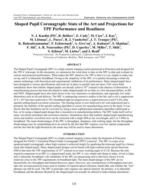
<strong>Shaped</strong> <strong>Pupil</strong> <strong>Coronagraph</strong>: <strong>State</strong> <strong>of</strong> <strong>the</strong> <strong>Art</strong> <strong>and</strong> <strong>Projections</strong><strong>for</strong> <strong>TPF</strong> Per<strong>for</strong>mance <strong>and</strong> Readiness Exoplanet Detection with <strong>Coronagraph</strong>s 2006<strong>Shaped</strong> <strong>Pupil</strong> <strong>Coronagraph</strong>: <strong>State</strong> <strong>of</strong> <strong>the</strong> <strong>Art</strong> <strong>and</strong> <strong>Projections</strong> <strong>for</strong><strong>TPF</strong> Per<strong>for</strong>mance <strong>and</strong> ReadinessN. J. Kasdin (PI) 1 , R. Belikov 1 , E. Cady 1 , M. Carr 1 , J. Kay 1 ,M. Littman 1 , L. Pueyo 1 , R. J. V<strong>and</strong>erbei 1 , J. T. Trauger (PI) 2 ,K. Balasubramanian 2 , P. Echternach 2 , A. Give’on 2 , A. Kuhnert 2 , S. Shaklan 2 ,F. Shi 2 , A. R. Neureu<strong>the</strong>r (PI) 3 , D. Ceperley 3 , M. Miller 3 , T. Shih 3 ,S. Kilston 4 , M. Lieber 4 , <strong>and</strong> J. Beall 51 Princeton University, 2 Jet Propulsion Laboratory, Cali<strong>for</strong>nia Instiute <strong>of</strong> Technology,3 Univeristy <strong>of</strong> Cali<strong>for</strong>nia, Berkeley, 4 Ball Aerospace, <strong>and</strong> 5 NISTABSTRACTThe <strong>Shaped</strong> <strong>Pupil</strong> <strong>Coronagraph</strong> (SPC) is a high-contrast imaging system pioneered at Princeton <strong>and</strong> designed <strong>for</strong><strong>the</strong> <strong>TPF</strong>-C telescope. In this document, we summarize <strong>the</strong> work done to date on <strong>the</strong> SPC to date <strong>and</strong> evaluate itscurrent <strong>and</strong> projected per<strong>for</strong>mance. What makes <strong>the</strong> SPC attractive <strong>for</strong> <strong>TPF</strong> is that it is very simple to make <strong>and</strong>set up, <strong>and</strong> it is inherently broadb<strong>and</strong>. Owing to <strong>the</strong> simplicity <strong>of</strong> <strong>the</strong> SPC, it is quickly becoming a relativelymature technology with <strong>the</strong>oretical <strong>and</strong> experimental validations <strong>of</strong> its per<strong>for</strong>mance. Many shaped pupils havebeen designed to various specifications <strong>and</strong> tools are in place to quickly turn out more. Full vector-fieldsimulations show that realistic shaped pupils can already achieve 10 10 contrast in <strong>the</strong> absence <strong>of</strong> aberrations. Amanufacturing process has been developed to make shaped pupils <strong>for</strong> as little as a few thous<strong>and</strong> dollars, at JPL<strong>and</strong> NIST. <strong>Shaped</strong> pupils have also been shown to be very insensitive to aberrations, <strong>and</strong> especially low orderaberrations such as tilt <strong>and</strong> defocus. The SPC is undergoing extensive studies in <strong>the</strong> lab, <strong>and</strong> so far a suppression<strong>of</strong> 4 × 10 -8 has been achieved in 10% broadb<strong>and</strong> light (averaged across a region between 4 <strong>and</strong> 9 λ/D), afterspeckle-nulling-based wavefront correction. The limiting factor is now believed to be well-understood <strong>and</strong> isprimarily <strong>the</strong> inability <strong>of</strong> <strong>the</strong> speckle nulling algorithm to correct <strong>for</strong> manufacturing errors in <strong>the</strong> mask. It wasshown that this limitation can be overcome by using a more sophisticated estimation algorithm called peak-aboo,or by using a shaped pupil design that is insensitive to manufacturing defects. The SPC lends itself well tomany wavefront estimation <strong>and</strong> correction schemes. Simulations show that realistic shaped pupil manufacturingerrors <strong>and</strong> realistic wavefront error can be corrected with a single DM at one wavelength, <strong>and</strong> 2 or 3 DMs inbroadb<strong>and</strong>. The main disadvantages <strong>of</strong> <strong>the</strong> SPC is throughput, sharpness, <strong>and</strong> working angle, but <strong>the</strong> throughputdisadvantage may be counterbalanced to an extent by <strong>the</strong> fact that SPC requires very few optical components<strong>and</strong> <strong>the</strong> fact that <strong>the</strong> light blocked by <strong>the</strong> mask may still be used to sense aberrations.INTRODUCTIONThe <strong>Shaped</strong> <strong>Pupil</strong> <strong>Coronagraph</strong> (SPC) is a high-contrast imaging system under development at Princeton,designed <strong>for</strong> NASA’s Terrestrial Planet Finder <strong>Coronagraph</strong> (<strong>TPF</strong>-C) mission 1 . The SPC is a type <strong>of</strong> anapodized-pupil coronagraph, where high contrast is achieved simply by apodizing <strong>the</strong> telescope pupil by a binarymask (<strong>the</strong> shaped pupil). Many shaped pupil designs can be found with high-contrast point spread functions(PSFs) that meet <strong>the</strong> <strong>TPF</strong> requirements <strong>of</strong> 10 10 contrast at an inner working angle <strong>of</strong> 4 λ/D. Because <strong>the</strong> onlyrequired component in an SPC is a shaped pupil mask, <strong>the</strong> SPC is very simple <strong>and</strong> cheap to make, trivial to align,<strong>and</strong> is inherently broadb<strong>and</strong>. Lab validations <strong>of</strong> <strong>the</strong> SPC are progressing <strong>and</strong> to date have shown it to berelatively close to <strong>the</strong> <strong>TPF</strong> requirements in broadb<strong>and</strong> light. The main disadvantages <strong>of</strong> <strong>the</strong> SPC are its<strong>the</strong>oretically low throughput <strong>and</strong> limited discovery space. However, any considerations <strong>of</strong> throughput must alsotake into account practical issues such as number <strong>of</strong> required optical elements, b<strong>and</strong>width, <strong>and</strong> whe<strong>the</strong>r <strong>the</strong> “lost”photons can still be used. The SPC in principle only requires one optical element: <strong>the</strong> primary, it is inherentlybroadb<strong>and</strong>, <strong>and</strong> <strong>the</strong> photons blocked by <strong>the</strong> shaped pupil can actually be utilized to help estimate aberrations.126
Exoplanet Detection with <strong>Coronagraph</strong>s 2006<strong>Shaped</strong> <strong>Pupil</strong> <strong>Coronagraph</strong>: <strong>State</strong> <strong>of</strong> <strong>the</strong> <strong>Art</strong> <strong>and</strong> <strong>Projections</strong><strong>for</strong> <strong>TPF</strong> Per<strong>for</strong>mance <strong>and</strong> ReadinessThere<strong>for</strong>e, <strong>the</strong> SPC’s low <strong>the</strong>oretical throughput may in fact be counterbalanced by gains in this practicalthroughput.A rough schematic <strong>of</strong> <strong>the</strong> baseline option <strong>of</strong> <strong>the</strong> <strong>TPF</strong>-C telescope with an SPC <strong>and</strong> a wavefront correction systemis shown in Figure 1. The system consists <strong>of</strong> <strong>the</strong> <strong>TPF</strong> telescope, followed by <strong>the</strong> wavefront correction system <strong>and</strong><strong>the</strong> SPC. The wavefront correction system can be designed to a large extent independently <strong>of</strong> <strong>the</strong> SPC, so we donot show its details here. The SPC consists <strong>of</strong> <strong>the</strong> shaped pupil at a reimaged pupil plane, <strong>and</strong> <strong>the</strong> science camerawith an optional star occulter if <strong>the</strong> camera itself is incapable <strong>of</strong> properly accepting light intensity with a 10 10dynamic range. The star occulter is a hard-edged mask designed to block <strong>the</strong> brightest portions <strong>of</strong> <strong>the</strong> PSF. If <strong>the</strong>star occulter cannot be placed very close to <strong>the</strong> chip, <strong>the</strong> science camera can be placed at a reimaged image planedownstream from <strong>the</strong> star occulter. Aside from imaging planets, <strong>the</strong> science camera will also be used to estimateaberrations <strong>and</strong> feed this estimation data back to <strong>the</strong> wavefront correction system (additional cameras can also beused <strong>for</strong> this purpose).Figure 1: Simplified schematic diagram <strong>of</strong> <strong>the</strong> <strong>TPF</strong> telescope with ashaped pupil coronagraph. The shaped pupil can be placed invirtually any "pupil" planeEven though our baseline position <strong>for</strong><strong>the</strong> shaped pupil is as shown by <strong>the</strong>solid line in Figure 1, <strong>the</strong> shaped pupilcan be located in many o<strong>the</strong>r planes,such as those indicated by <strong>the</strong> dottedlines. In fact, one attractive design is asingle-mirror prime-focus telescopewith a shaped pupil ei<strong>the</strong>r in front <strong>of</strong> <strong>the</strong>primary or along <strong>the</strong> converging beamdownstream. Such a prime-focus designis attractive not only because it is sosimple, but also because it eliminateslight losses <strong>and</strong> aberrations introducedby all optics except <strong>for</strong> <strong>the</strong> primary. (Infact, this design has no phase-inducedamplitude or similar aberrations.) However, <strong>the</strong> prime-focus design may not be practical because it requires <strong>the</strong>ability to shape <strong>the</strong> primary to be free <strong>of</strong> aberrations <strong>and</strong> a few o<strong>the</strong>r technical challenges.SHAPED PUPIL DESIGN AND MANUFACTURE<strong>Shaped</strong> pupils are designed by specifying contrast as well as <strong>the</strong> areas in <strong>the</strong> PSF where this contrast is to beachieved (dark zones), <strong>and</strong> running nonlinear optimization techniques on <strong>the</strong> pupil shapes to optimizethroughput 2 . Many pupil designs <strong>and</strong> design types were created over <strong>the</strong> years (see, e.g., V<strong>and</strong>erbei et al. 2004 3 ),but we have identified <strong>the</strong> so-called “ripple” design type as being <strong>the</strong> easiest to manufacture as a free-st<strong>and</strong>ingmask. Some <strong>of</strong> <strong>the</strong> designs we manufactured (by NIST <strong>and</strong>/or JPL 4 ) are shown in Figure 2. The manufacturingprocess was deep reactive ion etching <strong>of</strong> silicon wafers. Mask were manufactured in both 10 <strong>and</strong> 25mmdiameters. Ripple 1 was designed <strong>for</strong> <strong>the</strong> elliptical shape <strong>of</strong> <strong>TPF</strong>-C while ripple 3 was designed <strong>for</strong> a circularpupil. As could be seen by <strong>the</strong> horizontal cross-sections in <strong>the</strong> bottom row <strong>of</strong> Figure 2, both were designed toachieve better than 10 -9 contrast at an inner working angle <strong>of</strong> 4λ/D. Both have about 10% Airy throughput (i.e.,<strong>the</strong> fraction <strong>of</strong> <strong>the</strong> input beam power that falls in <strong>the</strong> main lobe <strong>of</strong> <strong>the</strong> PSF). As could be seen from <strong>the</strong> PSFs inFigure 2, <strong>the</strong> dark zone <strong>for</strong> ripple 1 has 45° openings on two sides <strong>of</strong> <strong>the</strong> main lobe, <strong>and</strong> ripple 3 has 90°openings. As mentioned be<strong>for</strong>e, <strong>the</strong> <strong>the</strong>oretically low throughput <strong>of</strong> <strong>the</strong> shaped pupils can be compensated <strong>for</strong> tosome extent by <strong>the</strong> fact that <strong>the</strong> SPC does not require any optics in addition to <strong>the</strong> shaped pupil, which eliminateslosses due to reflections; <strong>and</strong> <strong>the</strong> fact that <strong>the</strong> SCP is inherently broadb<strong>and</strong>, so that any photon losses due tonarrow-b<strong>and</strong> filtering are eliminated.127
<strong>Shaped</strong> <strong>Pupil</strong> <strong>Coronagraph</strong>: <strong>State</strong> <strong>of</strong> <strong>the</strong> <strong>Art</strong> <strong>and</strong> <strong>Projections</strong><strong>for</strong> <strong>TPF</strong> Per<strong>for</strong>mance <strong>and</strong> Readiness Exoplanet Detection with <strong>Coronagraph</strong>s 2006Ripple 1Ripple 3Manufacturing-500-500-2-20-4-60-4-6-8-850 -10-50 0 5050 -10-50 0 5010 010 010 -510 -510 -1010 -1010 -150 10 20 30 40 5010 -150 10 20 30 40 50Figure 2: Left two columns: examples <strong>of</strong> shaped pupil designs. Top row is <strong>the</strong> shaped pupil(white is transmissive); second row is <strong>the</strong> PSF, showing <strong>the</strong> high-contrast regions in blue; <strong>and</strong>third row is <strong>the</strong> horizontal slice through <strong>the</strong> PSF. All axes are in units <strong>of</strong> λ/D. Right column:microscope pictures <strong>of</strong> a manufactured mask.MASK SIMULATIONSThe shaped pupils are designed assuming that <strong>the</strong> masks will be ideal <strong>and</strong> that <strong>the</strong> image plane is an exactFourier Trans<strong>for</strong>m <strong>of</strong> <strong>the</strong> pupil plane. One important question is whe<strong>the</strong>r <strong>the</strong>se assumptions are valid in practice.In this section, we present <strong>the</strong> results <strong>of</strong> full vector simulations that show that in most cases <strong>of</strong> interest, <strong>the</strong>seassumptions are indeed valid.Ceperly et al. 5 have per<strong>for</strong>med finite-difference-time-domain simulations <strong>of</strong> <strong>the</strong> interactions between <strong>the</strong> vectorelectro-magnetic fields <strong>and</strong> <strong>the</strong> edges <strong>of</strong> a realistic mask (i.e., real material, non-0 thickness) <strong>and</strong> compared <strong>the</strong>results to <strong>the</strong> assumption <strong>of</strong> an ideal mask (i.e., ideal apodization, 0 thickness). The main results are summarizedin Figure 3. The left column specifies various cases that were simulated <strong>and</strong> <strong>the</strong> right column shows <strong>the</strong>magnitude <strong>of</strong> <strong>the</strong> difference between a real <strong>and</strong> an ideal mask (taking <strong>the</strong> worst case <strong>for</strong> <strong>the</strong> last 5 rows). By“vertical sidewalls”, we mean <strong>the</strong> case where <strong>the</strong> edges <strong>of</strong> <strong>the</strong> mask have walls that <strong>for</strong>m a 90 degree angle withrespect to <strong>the</strong> substrate. By “20° undercut”, we mean that this angle is 90°–20° (with <strong>the</strong> mask opening beingnarrower on <strong>the</strong> illuminated side <strong>of</strong> <strong>the</strong> mask). “Xμm opening” refers to <strong>the</strong> width <strong>of</strong> <strong>the</strong> mask opening in crosssection. The value <strong>of</strong> <strong>the</strong> parameter on <strong>the</strong> right column (severity) corresponds to <strong>the</strong> width along <strong>the</strong> edge <strong>of</strong> <strong>the</strong>ideal mask that contains <strong>the</strong> same amount <strong>of</strong> energy as <strong>the</strong> perturbation due to <strong>the</strong> effect on <strong>the</strong> left column. Themain conclusions <strong>of</strong> <strong>the</strong>se simulations are that vertical sidewalls are to be avoided, <strong>and</strong> that small mask tilts,changes <strong>of</strong> polarization <strong>and</strong> wavelengths, <strong>and</strong> metal coatings are <strong>the</strong> least significant.128
Exoplanet Detection with <strong>Coronagraph</strong>s 2006<strong>Shaped</strong> <strong>Pupil</strong> <strong>Coronagraph</strong>: <strong>State</strong> <strong>of</strong> <strong>the</strong> <strong>Art</strong> <strong>and</strong> <strong>Projections</strong><strong>for</strong> <strong>TPF</strong> Per<strong>for</strong>mance <strong>and</strong> ReadinessMask Structure:Severity:Vertical sidewalls, Off-axis illumination, 10um Opening, 100um Thick7 λVertical sidewalls, Off-axis illumination, 10um Opening, 50um Thick4 λVertical sidewalls, On-axis illumination, 10um Opening, 100um Thick3–4 λVertical sidewalls, On-axis illumination, 10um Opening, 50um Thick3 λVertical sidewalls, On-axis illumination, 48um Opening, 50um Thick3 λVertical sidewalls, On-axis illumination, 48um Opening, 50um Thick2–3 λ20° undercut sidewalls, On-axis illumination, 48um Opening, 50um Thick λ / 4Physical effects on 50um thick Si masks with 48um openings at 630nm:Worst case:Undercut angle3 λSmall mask tiltλ / 2 per degree tiltPolarization λ / 4Wavelength (630nm to 785nm) λ / 4200nm Cr top-coat λ / 100Figure 3: Extent <strong>of</strong> different effects on <strong>the</strong> fields around <strong>the</strong> edges.This data was used to study how vector interactions with <strong>the</strong> real mask affect <strong>the</strong> PSF <strong>of</strong> <strong>the</strong> real mask (Lieber etal 6 ). The main conclusions were that severities <strong>of</strong> less than λ/4 do not degrade <strong>the</strong> 10 10 contrast <strong>for</strong> mask sizes10 cm <strong>and</strong> larger. There<strong>for</strong>e, with a properly undercut mask, <strong>the</strong> mask can be assumed ideal <strong>and</strong> insensitive topolarization, wavelength changes, or coatings. For masks that are not undercut, <strong>the</strong> degradation depends on <strong>the</strong>mask type <strong>and</strong> size. In a 10 cm ripple mask, contrast is degraded to 10 9 , while <strong>for</strong> a 10 cm checkerboard mask,contrast is not degraded. All such effects will be insignificant compared to wavefront error. One importantcorollary to this work is that manufacturing error or imprecision <strong>of</strong> <strong>the</strong> edges as large as λ/4 is insignificant (atleast to <strong>the</strong> extent that manufacturing errors along <strong>the</strong> edges are similar to effective errors due to vector effects).Such an error is well within modern manufacturing tolerances. The results presented in this section indicate thatreal masks can be manufactured today which, in <strong>the</strong> absence <strong>of</strong> wavefront aberrations, will achieve <strong>the</strong> 10 10contrast required by <strong>TPF</strong> (except <strong>for</strong> <strong>the</strong> trimming limitation discussed later, which can be overcome byspecialized mask designs).SENSITIVITY TO WAVEFRONT ABERRATIONSIn order to assess <strong>the</strong> sensitivity <strong>of</strong> shaped pupils to wavefront aberrations, we simulated different Zernikeaberrations at <strong>the</strong> pupil plane <strong>and</strong> studied <strong>the</strong>ir effects at <strong>the</strong> image plane 7,8 . Some <strong>of</strong> <strong>the</strong>se results aresummarized in Figure 4. For <strong>the</strong>se simulations, we assumed a circular concentric ring shaped pupil. Each subplotcorresponds to a different Zernike (starting from tilt, defocus, etc.), <strong>and</strong> shows <strong>the</strong> contrast in <strong>the</strong> image plane ata particular working angle (4 or 8 λ/D) as a function <strong>of</strong> RMS <strong>of</strong> aberration. Just as with many o<strong>the</strong>rcoronagraphs, <strong>the</strong> sensitivity is more pronounced at lower inner working angles <strong>and</strong> higher Zernike orders. Themain conclusion <strong>of</strong> this work, however, is that <strong>the</strong> SPC is very insensitive to aberrations (especially to pointingerror or o<strong>the</strong>r <strong>for</strong>ms <strong>of</strong> tilt, defocus, <strong>and</strong> astigmatism). The wavefront flatness requirement depends on <strong>the</strong>aberration, but assuming typical power spectral density fall-<strong>of</strong>f such as 1/f 3 , <strong>the</strong> total flatness requirement needsto be on <strong>the</strong> order <strong>of</strong> λ/10,000.129
<strong>Shaped</strong> <strong>Pupil</strong> <strong>Coronagraph</strong>: <strong>State</strong> <strong>of</strong> <strong>the</strong> <strong>Art</strong> <strong>and</strong> <strong>Projections</strong><strong>for</strong> <strong>TPF</strong> Per<strong>for</strong>mance <strong>and</strong> Readiness Exoplanet Detection with <strong>Coronagraph</strong>s 20064 λ /D10 -5 (1,1)10 -5 (2,0)8 λ .D10 -1010 -1010 -4 10 -3 10 -2 10 -110 -4 10 -3 10 -2 10 -110 -5(2,2)10 -5 (3,1)10 -5 (3,3)Contrast10 -1010 -1010 -1010 -4 10 -3 10 -2 10 -110 -4 10 -3 10 -2 10 -110 -4 10 -3 10 -2 10 -110 -5 (4,0)(4,2)10 -5 (4,4)10 -1010 -1010 -4 10 -3 10 -2 10 -110 -1010 -4 10 -3 10 -2 10 -110 -5 RM S <strong>of</strong> aberration in units <strong>of</strong> wave10 -4 10 -3 10 -2 10 -1Figure 4: Sensitivity to different Zernike aberrations <strong>for</strong> a concentric ring shaped pupil mask asa function <strong>of</strong> RMS <strong>of</strong> aberrations, at inner working angles <strong>of</strong> 4 <strong>and</strong> 8 λ/D. The title <strong>of</strong> each graphis <strong>the</strong> Zernike radial <strong>and</strong> azimuthal index.LABORATORY RESULTSExperimental validation <strong>of</strong> shaped pupils is currently under way at Princeton <strong>and</strong> JPL 9,10 . The Princeton testbedis relatively new <strong>and</strong> low cost, consisting <strong>of</strong> an optical bench with an enclosure in a semi-clean room, <strong>and</strong> 2recently acquired Boston Micromachines DMs. We are currently getting contrast levels <strong>of</strong> about 10 5 withoutwavefront correction <strong>and</strong> about 10 6 with wavefront correction. Both values hold <strong>for</strong> <strong>the</strong> largest b<strong>and</strong>width wetried, ~450–750 nm, demonstrating <strong>the</strong> broadb<strong>and</strong> advantage <strong>of</strong> shaped pupils. Simulations indicate that <strong>the</strong>contrast-limiting factor <strong>for</strong> us is tw<strong>of</strong>old. One, we are using a small mask (10 mm) because <strong>of</strong> <strong>the</strong> small size <strong>of</strong>our DM. Any manufacturing errors are proportionately greater <strong>for</strong> smaller masks, <strong>and</strong> in our case <strong>the</strong>y appear atabout 10 -6 level. Two, <strong>the</strong> correction algorithm we are currently using, speckle nulling, is incapable <strong>of</strong> correcting<strong>for</strong> errors <strong>of</strong> this kind. Hence, we expect to be able to reach much better contrast if we ei<strong>the</strong>r (a) adopt our setupto be able to accommodate a larger mask given <strong>the</strong> small DM without degrading contrast; (b) design a maskmore tolerant to manufacturing limitations, or (c) use a more sophisticated correction algorithm such as peak-aboo11 . We are currently pursuing all three, with a focus on (c). Simulations show that peak-a-boo is capable <strong>of</strong>correcting <strong>for</strong> errors due to manufacturing defects which are beyond <strong>the</strong> ability <strong>of</strong> speckle nulling.130
Exoplanet Detection with <strong>Coronagraph</strong>s 2006<strong>Shaped</strong> <strong>Pupil</strong> <strong>Coronagraph</strong>: <strong>State</strong> <strong>of</strong> <strong>the</strong> <strong>Art</strong> <strong>and</strong> <strong>Projections</strong><strong>for</strong> <strong>TPF</strong> Per<strong>for</strong>mance <strong>and</strong> ReadinessFigure 5: Contrast plots from tests at <strong>the</strong> HCIT. Top left: one <strong>of</strong> <strong>the</strong> starting speckle nulling iterations (iteration4) at 785 nm. Top right: one <strong>of</strong> <strong>the</strong> final iterations (iteration 452). The higher amount <strong>of</strong> noise in <strong>the</strong> image <strong>of</strong>iteration 4 is due to lower exposure time. Middle left: horizontal traces through <strong>the</strong> centers. Middle right: scatterplots in <strong>the</strong> dark region. Bottom left: after changing from 785- to 836-nm light. Bottom right: after changing tobroadb<strong>and</strong> light. For <strong>the</strong> λ/D scale, λ = 785 nm <strong>and</strong> D = 25 mm.JPL’s testbed (HCIT), on <strong>the</strong> o<strong>the</strong>r h<strong>and</strong>, is somewhat more sophisticated than <strong>the</strong> one at Princeton, consisting <strong>of</strong>a vacuum chamber in a clean room <strong>and</strong> a having a large DM 12 . Owing to this, our best results to date are from anexperiment per<strong>for</strong>med at HCIT with a 25-mm shaped pupil, where we have achieved suppression <strong>of</strong> 4 × 10 -8with speckle nulling. Simulations show that this is about <strong>the</strong> level <strong>of</strong> contrast due to manufacturing limitations(trimming) <strong>for</strong> <strong>the</strong> particular shaped pupil we used. Work is progressing on a design <strong>and</strong> manufacturing processcapable <strong>of</strong> yielding a mask with no significant manufacturing defects.131
<strong>Shaped</strong> <strong>Pupil</strong> <strong>Coronagraph</strong>: <strong>State</strong> <strong>of</strong> <strong>the</strong> <strong>Art</strong> <strong>and</strong> <strong>Projections</strong><strong>for</strong> <strong>TPF</strong> Per<strong>for</strong>mance <strong>and</strong> Readiness Exoplanet Detection with <strong>Coronagraph</strong>s 2006Our experimental setup at HCIT was designed to take an image <strong>of</strong> <strong>the</strong> PSF <strong>of</strong> <strong>the</strong> shaped pupil. A DM waspresent in a pupil plane upstream <strong>of</strong> <strong>the</strong> shaped pupil to correct <strong>for</strong> aberrations. A bowtie-shaped star occulterwas used in an image plane upstream <strong>of</strong> <strong>the</strong> camera to prevent a lot <strong>of</strong> bright light hitting <strong>the</strong> CCD. Specklenulling was per<strong>for</strong>med at 785 nm <strong>and</strong> <strong>the</strong>n <strong>the</strong> wavelength was switched to 836nm <strong>and</strong> to 760–840 nmbroadb<strong>and</strong> light. The results are shown in Figure 5. Without any corrections, <strong>the</strong> contrast on <strong>the</strong> HCIT testbed issimilar to <strong>the</strong> Princeton testbed, or 10 5 at 4 λ/D (<strong>the</strong> HCIT system was already slightly corrected when westarted, so that <strong>the</strong> starting point is closer to 10 6 ). After wavefront correction, <strong>the</strong> suppression is 4 × 10 -8 between4 <strong>and</strong> 9 λ/D (averaged across <strong>the</strong> dark region). As can be seen from Figure 5, this contrast is maintained afterswitching to ei<strong>the</strong>r 836nm or broadb<strong>and</strong> light, once again demonstrating achromaticity <strong>of</strong> shaped pupils.WAVEFRONT SENSING AND CONTROLSpeckle nulling is a very robust <strong>and</strong> simple method <strong>of</strong> wavefront correction, but it has certain limitations,notably speed <strong>and</strong> inability to correct <strong>for</strong> certain kinds <strong>of</strong> aberrations. More sophisticated methods are necessary<strong>for</strong> use in space. Many correction methods are being developed <strong>for</strong> or can be adopted <strong>for</strong> use with <strong>the</strong> SPC. Thehardware necessary <strong>for</strong> various methods is outlined in Figure 6, along with a few notes on each method. Thesimplest methods are those that involve <strong>the</strong> use <strong>of</strong> <strong>the</strong> science camera, in conjunction with algorithms such asPeak-a-boo 11 or Borde <strong>and</strong> Traub’s method 13 . One disadvantage <strong>of</strong> <strong>the</strong>se, however, is that speckles in <strong>the</strong> imageplane are blurred in broadb<strong>and</strong> light, <strong>and</strong> hence <strong>the</strong> per<strong>for</strong>mance suffers with b<strong>and</strong>width. An alternative that isnot sensitive to b<strong>and</strong>width is to image <strong>the</strong> pupil plane after <strong>the</strong> star occulter. The price is additional complexity<strong>and</strong> possible slight loss <strong>of</strong> throughput. However, both <strong>of</strong> <strong>the</strong>se methods work with light after <strong>the</strong> star occulter<strong>and</strong>, <strong>the</strong>re<strong>for</strong>e, do not get a lot <strong>of</strong> photons. Guyon proposed that light blocked by <strong>the</strong> star occulter can be used toestimate low-order aberrations. A variation on this <strong>the</strong>me is to use <strong>the</strong> light reflected <strong>of</strong>f <strong>the</strong> shaped pupil. Both<strong>of</strong> <strong>the</strong>se schemes can be used in addition to <strong>the</strong> first two mentioned.Figure 6: Schematic diagram <strong>of</strong> wavefront sensing options.132
Exoplanet Detection with <strong>Coronagraph</strong>s 2006<strong>Shaped</strong> <strong>Pupil</strong> <strong>Coronagraph</strong>: <strong>State</strong> <strong>of</strong> <strong>the</strong> <strong>Art</strong> <strong>and</strong> <strong>Projections</strong><strong>for</strong> <strong>TPF</strong> Per<strong>for</strong>mance <strong>and</strong> ReadinessThe ability to sense <strong>and</strong> correct <strong>for</strong> aberrations all <strong>the</strong> way to 10 10 contrast in a SPC system that has real maskslike those already manufactured today has already been shown <strong>the</strong>oretically in monochromatic light. Figure 7shows a simulation <strong>of</strong> Peak-a-boo estimation <strong>and</strong> subsequent correction (assuming an ideal DM), in a systemhaving phase <strong>and</strong> amplitude errors as well as <strong>the</strong> observed manufacturing errors (trimming) on <strong>the</strong> mask.Such corrections work well <strong>for</strong> monochromatic light, or even in polychromatic light assuming no wavelengthdependence <strong>of</strong> aberrations. However, in reality, both phase <strong>and</strong> amplitude error will have a non-negligibledependency on wavelength, due to a variety <strong>of</strong> mechanisms 15 , severely limiting <strong>the</strong> b<strong>and</strong>width across whichaberrations can be fully corrected. None<strong>the</strong>less, in such cases, <strong>the</strong> required 10 10 contrast can still be achievedwith <strong>the</strong> SPC if one uses more than 1 DM <strong>for</strong> correction. Figure 8 shows some possible configurations <strong>of</strong> 2 <strong>and</strong> 3DMs designed to correct <strong>for</strong> wavelength-dependent errors along with a simulation <strong>of</strong> correcting <strong>for</strong> such errorswith a 3-DM correction system.Figure 7: Demonstration <strong>of</strong> Peak-a-boosensing <strong>and</strong> correction with a realisticshaped pupil having manufacturingdefects (trimming), in monochromaticlight.Figure 8: Top: Multi-DMconfigurations that allowcorrections <strong>for</strong> realisticwavelength-dependent errors.Bottom: Even a severe case wherewavelength-dependent aberrationslimit <strong>the</strong> contrast to 10 3 can befully corrected by a system <strong>of</strong> 3DMs. In this simulation, perfectestimation <strong>of</strong> <strong>the</strong> aberrations isassumed.133
Exoplanet Detection with <strong>Coronagraph</strong>s 2006ACKNOWLEDGEMENTSThe Princeton group gratefully acknowledges <strong>the</strong> support <strong>of</strong> <strong>the</strong> National Aeronautics <strong>and</strong> Space Administrationthrough <strong>the</strong> Jet Propulsion Laboratory, as well as <strong>the</strong> Michelson Science Center, Cali<strong>for</strong>nia Institute <strong>of</strong>Technology <strong>for</strong> this work.REFERENCES1. Kasdin, N. J., Belikov, R., Beall, J., V<strong>and</strong>erbei, R. J., Littman, M. G., Carr, M., & Give'on, A., "<strong>Shaped</strong><strong>Pupil</strong> <strong>Coronagraph</strong>s <strong>for</strong> Planet Finding: Optimization, Manufacturing, <strong>and</strong> Experimental Results," Proc. <strong>of</strong>SPIE 5905, G1-G8, (2005).2. Kasdin, N. J., V<strong>and</strong>erbei, R. J., Spergel, D. N., & Littman, M. G., "Extrasolar Planet Finding via OptimalApodized <strong>and</strong> <strong>Shaped</strong> <strong>Pupil</strong> <strong>Coronagraph</strong>s," Astrophysical Journal 582, 1147-1161, (2003).3. V<strong>and</strong>erbei, R. J., Kasdin, N. J., & Spergel, D. N., "Checkerboard-Mask <strong>Coronagraph</strong>s <strong>for</strong> High-ContrastImaging," Astrophysical Journal 615(2004).4. Balasubramanian, K., et al., "Fabrication <strong>and</strong> Characteristics <strong>of</strong> Free St<strong>and</strong>ing <strong>Shaped</strong> <strong>Pupil</strong> Masks <strong>for</strong> <strong>TPF</strong>-<strong>Coronagraph</strong>," Proc. <strong>of</strong> SPIE, 6265 (2006).5. Ceperley, Daniel; Neureu<strong>the</strong>r, Andrew; Miller, Marshall; Lieber, Michael; Kasdin, Jeremy, "Stray-lightsources from pupil mask edges <strong>and</strong> mitigation techniques <strong>for</strong> <strong>the</strong> <strong>TPF</strong> <strong>Coronagraph</strong>," Proc. <strong>of</strong> SPIE,6271(2006).6. Lieber, Mike; Neureu<strong>the</strong>r, Andrew R.; Ceperley, Dan; Kasdin, Jeremy; Hoppe, Dan; Eisenman, Allan, "Evaluating <strong>the</strong> end-to-end per<strong>for</strong>mance <strong>of</strong> <strong>TPF</strong>-C with vector propagation models: Part I. <strong>Pupil</strong> maskeffects," Proc. <strong>of</strong> SPIE, 5906 (2005).7. Belikov, R., Kasdin, N. J., V<strong>and</strong>erbei, R. J., "Diffraction-based Sensitivity Analysis <strong>of</strong> Apodized <strong>Pupil</strong>mappingSystems," Astrophysical Journal 652 (2006).8. Shaklan, Stuart B.; Green, Joseph J., "Low-Order Aberration Sensitivity <strong>of</strong> Eighth-Order <strong>Coronagraph</strong>Masks," Astrophyciscal Journal 628 (2005).9. Belikov, Ruslan; Give'on, Amir; Trauger, John T.; Carr, Michael; Kasdin, N. J.; V<strong>and</strong>erbei, Robert J.; Shi,Fang; Balasubramanian, Kunjithapatham; Kuhnert, Andreas, "Toward 10 10 contrast <strong>for</strong> terrestrial exoplanetdetection: demonstration <strong>of</strong> wavefront correction in a shaped-pupil coronagraph," Proc. <strong>of</strong> SPIE, 6265(2006).10. Belikov, Ruslan; Beall, James; Carr, Michael; Give'On, Amir; Kay, Jason; Kolade, Ta<strong>of</strong>ik; Littman,Michael; Mycr<strong>of</strong>t, Frank; Pueyo, Laurent; V<strong>and</strong>erbei, Robert J.; Kasdin, N. Jeremy, " Towards 10 10 Contrast<strong>for</strong> NASA's Terrestrial Planet Finder Mission: Demonstration <strong>of</strong> High Contrast in a <strong>Shaped</strong>-<strong>Pupil</strong><strong>Coronagraph</strong> at Princeton," Proceedings <strong>of</strong> <strong>the</strong> IAU Colloquium #200, pp. 415-420, 2006.11. Give'On, Amir; Kasdin, N. Jeremy; V<strong>and</strong>erbei, Robert J., "Closed-loop Wavefront Correction <strong>for</strong> HighContrast Imaging: The ``peak-a-boo'' Algorithm," Proceedings <strong>of</strong> <strong>the</strong> IAU Colloquium #200, pp. 541-546,2006.12. Trauger, J., et al., "<strong>Coronagraph</strong> Contrast Demonstrations with <strong>the</strong> High Contrast Imaging Testbed," Proc. <strong>of</strong>SPIE 5487, 1330-1336, (2004).13. Bordé, Pascal J.; Traub, Wesley A., “High-Contrast Imaging from Space: Speckle Nulling in a Low-Aberration Regime,” Astrophysical Journal, 638 (2006).14. Guyon, O.; Pluzhnik, E. A.; Kuchner, M. J.; Collins, B.; Ridgway, S. T., “Theoretical Limits on ExtrasolarTerrestrial Planet Detection with <strong>Coronagraph</strong>s,” Astrophysical Journal Supplement Series, 167, (2006).15. Shaklan, Stuart B.; Green, Joseph J.; Palacios, David M., “The terrestrial planet finder coronagraph opticalsurface requirements,” Proc. <strong>of</strong> SPIE, 6265 (2006).134


