Von Duprin CS 98 9949 Installation Instructions - Access Hardware ...
Von Duprin CS 98 9949 Installation Instructions - Access Hardware ...
Von Duprin CS 98 9949 Installation Instructions - Access Hardware ...

Create successful ePaper yourself
Turn your PDF publications into a flip-book with our unique Google optimized e-Paper software.
23970734<br />
<strong>98</strong>/<strong>9949</strong><br />
<strong>CS</strong> <strong>98</strong>/<strong>9949</strong><br />
<strong>Installation</strong> <strong>Instructions</strong><br />
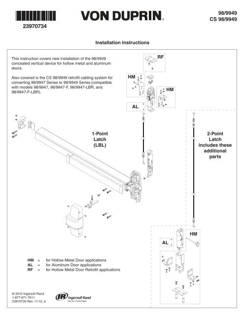
This instruction covers new installation of the <strong>98</strong>/<strong>9949</strong><br />
concealed vertical device for hollow metal and aluminum<br />
doors.<br />
RF<br />
Also covered is the <strong>CS</strong> <strong>98</strong>/<strong>9949</strong> retrofit cabling system for<br />
converting <strong>98</strong>/9947 Series to <strong>98</strong>/<strong>9949</strong> Series (compatible<br />
with models <strong>98</strong>/9947, <strong>98</strong>/9947-F, <strong>98</strong>/9947-LBR, and<br />
<strong>98</strong>/9947-F-LBR).<br />
HM<br />
HM<br />
AL<br />
1-Point<br />
Latch<br />
(LBL)<br />
2-Point<br />
Latch<br />
includes these<br />
additional<br />
parts<br />
HM<br />
AL<br />
HM<br />
AL<br />
RF<br />
= for Hollow Metal Door applications<br />
= for Aluminum Door applications<br />
= for Hollow Metal Door Retrofit applications<br />
© 2012 Ingersoll Rand<br />
1-877-671-7011<br />
23970734 Rev. 11/12_d
1 Identify Cable Sizes and Locations.<br />
(if not preinstalled in door)<br />
A<br />
!<br />
NOTE: For retrofit installations,<br />
begin at Step 5.<br />
For easy identification, each<br />
cable is labeled with door<br />
opening height and location.<br />
B<br />
CABLE IDENTIFICATION<br />
(STANDARD SIZES)<br />
HOLLOW METAL AND ALUMINUM DOORS<br />
Door Opening<br />
Height<br />
6' 8"<br />
7' 0"<br />
8' 0"<br />
9' 0"<br />
10' 0"<br />
A<br />
(Red Cable)<br />
80" Top<br />
84" Top<br />
96" Top<br />
108" Top<br />
120" Top<br />
B<br />
(White Cable)<br />
80" Bottom<br />
84" Bottom<br />
96" Bottom<br />
108" Bottom<br />
120" Bottom<br />
2 Install Cable(s).<br />
For 2-Point Latch Only<br />
a. Position red cable end to clip on center slide<br />
a<br />
clip<br />
Red<br />
b. Pull cable into clip to snap it into place<br />
c. Push cable snap against center slide to secure cable<br />
b<br />
c<br />
cable snap<br />
d. In the same way, install opposite end of red cable to top latch in the<br />
position marked red<br />
!<br />
IMPORTANT:<br />
Ensure cable end is<br />
fully seated in clip<br />
e. There is an adjuster on one end of the white cable. Install this end to the<br />
remaining top latch position (marked as white)<br />
! IMPORTANT:<br />
adjuster<br />
White<br />
f. Install opposite end of white cable to bottom latch<br />
e<br />
f<br />
Ensure cable end is<br />
fully seated in clip<br />
d<br />
CABLE REMOVAL<br />
A cable removal tool has been provided. Slot in tool fits over cable,<br />
holding tabs down. Pull on cable snap to loosen cable for removal.<br />
slot<br />
a<br />
cable<br />
snap<br />
b<br />
2
3 Determine if Bottom Latch Retraction Adjustment is<br />
Required.<br />
For 2-Point Latch Only<br />
4 Adjust Bottom Latch Retraction (if necessary).<br />
For 2-Point Latch Only<br />
a. Throughout this<br />
adjustment<br />
process, hold<br />
bottom latch<br />
alongside top<br />
latch to simulate<br />
the installed<br />
condition of the<br />
latches.<br />
b. To determine whether an<br />
adjustment is required, actuate<br />
the top latch to the hold-open<br />
position by pressing down on the<br />
connecting rod. Bottom latch<br />
should retract to within ¹⁄₁₆" of<br />
flush. If it does not, an adjustment<br />
is necessary.<br />
press<br />
If no adjustment is<br />
needed, proceed<br />
to Step 5.<br />
¹⁄₁₆"<br />
a. Before proceeding,<br />
return the top latch to<br />
the latched position by<br />
pulling in the direction<br />
shown.<br />
b. Secure the snap-fitting with a<br />
³⁄₈" wrench while loosening the<br />
locknut with a 10mm wrench.<br />
³⁄₈"<br />
top latch<br />
e. While securing the snap-fitting<br />
with a ³⁄₈" wrench, continue to<br />
tighten the locknut until it is<br />
secure.<br />
10mm<br />
snapfitting<br />
³⁄₈"<br />
flush<br />
top latch<br />
(hold-open<br />
position)<br />
bottom latch<br />
(retracted)<br />
lock nut<br />
10mm<br />
f. Actuate the top latch to the<br />
hold-open position to confirm<br />
that the bottom latch is secure<br />
and now retracts to within ¹⁄₁₆"<br />
of flush.<br />
c. Rotate the snap-fitting by hand<br />
until the slack is taken up. Do<br />
not overtighten.<br />
press<br />
¹⁄₁₆"<br />
flush<br />
snap-fitting<br />
top latch<br />
(hold-open<br />
position)<br />
bottom latch<br />
(retracted)<br />
d. Close the gap between the<br />
locknut and snap-fitting by<br />
turning the locknut in a<br />
clockwise direction using a<br />
10mm wrench while holding the<br />
conduit cap with the ³⁄₈" wrench.<br />
Stop when the gap is closed<br />
and the snap-fitting begins to<br />
turn with the locknut.<br />
10mm<br />
conduit<br />
cap<br />
³⁄₈"<br />
3
5 If Retrofit <strong>Installation</strong><br />
8 If Necessary, Prepare Door Cutouts.<br />
a. Remove device<br />
from existing<br />
door.<br />
b. Remove and<br />
discard existing<br />
door.<br />
c. Remove and<br />
discard existing<br />
strikes.<br />
6 With Door Laying Flat, Draw Horizontal Device<br />
Center Line ( ).<br />
RHR<br />
LHR<br />
RHR shown<br />
(LHR uses same<br />
cutout and hole<br />
orientation)<br />
Latch<br />
C L aligns with<br />
center of hole<br />
¹³⁄₁₆"<br />
1⁵⁄₈"<br />
⁷⁄₈"<br />
5⁷⁄₈"<br />
1³⁄₄"<br />
Device<br />
!<br />
NOTE: Centerline is predetermined by cutout. If no<br />
cutout exists, refer to Step 8 to determine centerline.<br />
7 Align Plastic Template and Mark Door.<br />
2¹⁵⁄₁₆"<br />
¹⁄₂" Dia.<br />
(Omit for<br />
EO, DT, & TL)<br />
3³⁄₄"<br />
39⁵⁄₈"<br />
to finished<br />
floor<br />
!<br />
NOTE: This hole is to be ¹⁄₂" diameter<br />
(disregard larger center hole of plastic<br />
template).<br />
¹⁄₂"<br />
1"<br />
2³⁄₄" Backset<br />
4¹⁄₄"<br />
Min. Stile<br />
Push side of door, RHR shown<br />
2³⁄₄"<br />
Backset<br />
Plastic<br />
Template<br />
4
9 If Necessary, Prepare 2 Center Slide Holes.<br />
10 Prepare 4 Holes per Plastic Template.<br />
RHR<br />
LHR<br />
¹⁄₄" Dia.<br />
82° Csk to ³⁄₈" Dia.<br />
Push Side Only<br />
(this hole is positioned<br />
to the left of centerline<br />
for both RHR and<br />
LHR)<br />
Latch<br />
¹⁄₄" Dia.<br />
#25<br />
Surface Mount<br />
(metal doors only)<br />
#10-24<br />
OR<br />
Sex Bolts or 990 Trims<br />
¹⁄₄" (device side)<br />
¹³⁄₃₂" (trim side)<br />
3¹⁄₂"<br />
⁹⁄₁₆"<br />
Device<br />
11 If Necessary, Prepare Door for Top Strike Cutout.<br />
⁹⁄₃₂"<br />
1¹⁄₄"<br />
Cut out material<br />
this side only<br />
⁹⁄₁₆"<br />
Latch<br />
Push side of door, RHR shown<br />
Push side of door, RHR shown<br />
12 Prepare <strong>Access</strong> Hole for Bottom Latch Adjustment Pin.<br />
Hollow Metal For 2-Point Latch Only<br />
³⁄₄" Dia. hole<br />
4¹⁄₄" depth<br />
clearance<br />
required<br />
Door<br />
Door<br />
3¹⁵⁄₁₆"<br />
⁵⁄₈" from<br />
push side<br />
of door<br />
⁵⁄₈" from<br />
push side<br />
of door<br />
Bottom of Door<br />
Door Edge<br />
RHR<br />
Door Edge<br />
LHR<br />
5
13 Assemble Latch Mounting Brackets.<br />
Hollow Metal<br />
Top<br />
3/4" 1/4"<br />
³⁄₄" mounting<br />
shown<br />
15 Prepare Bottom of Door for Latch Mounting.<br />
Aluminum For 2-Point Latch Only<br />
Latch<br />
3/4"<br />
1/4"<br />
3/4"<br />
1/4"<br />
Top Door Channel<br />
⁷⁄₃₂" Dia. x2<br />
82˚ Csk to ³⁄₈" Dia.<br />
2¹⁄₄"<br />
1¹⁄₂"<br />
Push Side of Door<br />
Bottom<br />
For 2-Point Latch Only<br />
16 If Using 696/697 Trim, Remove Center Slide<br />
Mounting Nut.<br />
14 Prepare Top of Door for Latch Mounting.<br />
Aluminum<br />
Latch<br />
center slide<br />
mounting nut<br />
³⁄₈" socket<br />
with ¹⁄₄" drive<br />
⁷⁄₃₂" Dia. x2<br />
82˚ Csk to ³⁄₈" Dia.<br />
3⁷⁄₁₆"<br />
1¹⁄₂"<br />
mounting nut has<br />
left-handed<br />
threading<br />
Push Side of Door<br />
17 Slide Latch and Center Slide Assembly thru Door.<br />
Top<br />
!<br />
NOTE: Confirm top latch (and bottom latch, if applicable) is in correct orientation before proceeding.<br />
1-Point Latch (LBL)<br />
Holes should face<br />
push side of door<br />
2-Point Latch<br />
Holes should face<br />
push side of door<br />
Holes should face<br />
push side of door<br />
Top<br />
6<br />
Hollow Metal Door application shown
18 Secure Center Slide to Door.<br />
19 Align Bottom Latch and Install Mounting Screws.<br />
Aluminum For 2-Point Latch Only<br />
Secure center slide to<br />
door by lightly<br />
tightening lower screw<br />
a<br />
Align upper hole<br />
visually<br />
b<br />
20 Secure Top Latch with 2 Screws.<br />
Aluminum<br />
Insert small screwdriver<br />
into upper hole to<br />
prevent center slide<br />
from rotating<br />
c<br />
Fully tighten lower<br />
screw<br />
d<br />
21 Install Bottom Latch Mounting Bracket Assembly.<br />
Hollow Metal For 2-Point Latch Only<br />
#25<br />
!<br />
NOTE: Confirm correct orientation of assembly<br />
before proceeding. Open side of housing<br />
should face pull side of door.<br />
#10-24 Push Side<br />
of Door<br />
If using<br />
³⁄₄" undercut door<br />
!<br />
NOTE: Use 2 screws per<br />
bracket (center hole not<br />
used for this application).<br />
spacer blocks (2)<br />
are required<br />
Spacer Block Kit<br />
(24231516)<br />
purchased separately<br />
7
22 Insert Latch Adjustment Pin to Hold Bottom Latch<br />
in Place.<br />
Hollow Metal For 2-Point Latch Only<br />
Pin must go thru<br />
both sides of<br />
bracket<br />
25 If Necessary, Remove NL Drive Screw.<br />
NL drive screw<br />
Factory installed on<br />
back of center case<br />
With the NL drive screw removed, key locks and unlocks lever, knob, or<br />
thumb piece. For the trims listed below, remove NL drive screw.<br />
996L *996L-BE 696TP *696TP-BE<br />
996K *996K-BE 697TP *697TP-BE<br />
990TP *990TP-BE<br />
With the NL drive screw installed, key retracts latch bolt. DO NOT remove<br />
NL drive screw for the following applications:<br />
NL, EO, DT, TP-2, L-2, and K-2 trims or with <strong>98</strong>/99-2 (double<br />
cylinder).<br />
Bottom edge of<br />
latch housing should<br />
be flush with bottom of door<br />
(for ³⁄₈" standard undercut)<br />
* If the trim being installed is "BE" (i.e. 996L-BE), the trim lock tumbler<br />
on the back of the device must be in the UP position before device<br />
is installed. This allows the trim to be unlocked at all times.<br />
Squeeze tabs on<br />
cap, then insert pin<br />
trim lock tumbler in<br />
UP position<br />
If necessary,<br />
rotate cam<br />
until trim lock<br />
tumbler is in<br />
UP position<br />
360˚<br />
23 Secure Top Latch Mounting Bracket.<br />
#25<br />
Hollow Metal<br />
Correct Orientation<br />
(RHR shown)<br />
Incorrect Orientation<br />
#10-24<br />
26 If Necessary, Cut Device.<br />
Door<br />
!<br />
NOTE: Use 2 screws per bracket<br />
(center hole not used for this<br />
application).<br />
Jamb<br />
1¹⁄₂" (38 mm)<br />
Recommended<br />
Jamb<br />
Temporarily Remove<br />
Anti-Rattle Clip<br />
24 Hang Door on Frame.<br />
Cover Plate<br />
Flush<br />
!<br />
CAUTION: For 2-point latches, bottom latch cannot be in locked<br />
position while hanging door on frame. Latch must be retracted.<br />
8
27 Install Top Center Slide Screw.<br />
29 Mark and Prepare 2 Holes.<br />
b<br />
a<br />
c<br />
Surface Mount (metal doors only)<br />
#25 #10-24<br />
¹⁄₄" (device side)<br />
OR<br />
Sex Bolts<br />
!<br />
NOTE: If using 696/697 trim, this screw<br />
will pass thru top center slide hole and<br />
secure directly into trim during Step 28.<br />
¹³⁄₃₂" (trim side)<br />
28 Attach Center Case to Door.<br />
Thru-bolting Trim<br />
30 Install End Cap Bracket and End Cap.<br />
(1³⁄₄" door)<br />
OR<br />
(2¹⁄₄" door)<br />
Surface Mount<br />
(metal doors only)<br />
Sex Bolts<br />
Surface Mount or Sex Bolts<br />
(1³⁄₄" door)<br />
(1³⁄₄" door)<br />
Sex Bolts<br />
(2¹⁄₄" door)<br />
(2¹⁄₄" door)<br />
9
31 If New <strong>Installation</strong>, Prepare Door Frame for Top<br />
Strike.<br />
34 Prepare Floor for Bottom Strike.<br />
Hollow Metal For 2-Point Latch Only<br />
Pull Side<br />
Latch<br />
Edge of stop<br />
Chisel out pocket<br />
¹⁄₂" Deep<br />
Latch<br />
⁷⁄₈"<br />
¹⁄₂"<br />
¹⁄₂"<br />
Use strike to mark<br />
location of 2 holes<br />
#25 x ¹⁄₂" Deep x2<br />
#10-24<br />
⁷⁄₈" 1" 1"<br />
³⁄₈" Dia. x 1¹⁄₄" Deep<br />
2 places<br />
Push Side<br />
32 If Retrofit <strong>Installation</strong>, Install Steel Cover Plate to<br />
Cover Existing 338 Strike Opening in Accordance<br />
with the Frame Manufacturer’s Fire Listing.<br />
35 Install Bottom Strike.<br />
Hollow Metal For 2-Point Latch Only<br />
Clear holes of debris, then<br />
drop in anchors (slotted end<br />
first)<br />
Secure the anchors using a<br />
hammer and punch<br />
a<br />
b<br />
a<br />
b<br />
!<br />
IMPORTANT:<br />
Anchors must<br />
be below flush.<br />
33 Install 2 Top Strike Screws Using the Slot Features<br />
on the Strike.<br />
Install strike plate and secure<br />
with 2 screws<br />
c<br />
249 Top Strike<br />
349 Bottom Strike<br />
10<br />
Retrofit installation
36 Prepare Threshold.<br />
Aluminum For 2-Point Latch Only<br />
a. After closing door with bottom latch installed, mark the location the<br />
bottom latch bolt is contacting the threshold.<br />
b. Drill a ³⁄₄" diameter hole in the threshold.<br />
38 Adjust Lift Finger.<br />
Loosen retainer clip<br />
screw<br />
a<br />
b<br />
Loosen adjustment<br />
screw until the lift<br />
finger drops and<br />
you feel contact<br />
with the center<br />
slide<br />
Latch bolt<br />
³⁄₄" Dia.<br />
Latch<br />
Stop<br />
Tighten retainer clip<br />
screw<br />
c<br />
37 Install Lift Finger and Retainer Clip.<br />
Slide L-shaped lift finger thru block in device<br />
center case and then into center slide<br />
For 2-Point Latch Only<br />
Push cable to the side<br />
so it does not interfere<br />
with lift finger.<br />
a<br />
Insert adjustment screw and<br />
rotate with screwdriver to<br />
raise lift finger until it is snug<br />
against block<br />
d<br />
39 Perform Functional Test of Door.<br />
a. Depress pushbar. Door should begin to open with pushbar depressed<br />
halfway. If necessary, refer to Step 38 to readjust lift finger.<br />
b. With door closed, top latch should be secure.<br />
For 2-Point Latch Only<br />
c. With door closed, bottom latch should be secure.<br />
b<br />
Lift finger must pass<br />
below locking tumbler<br />
(back of center case<br />
shown for clarity)<br />
c<br />
Lift finger must insert<br />
into center slide here<br />
d. Confirm that bottom latch does not drag against floor when door is<br />
opened.<br />
Hollow Metal For 2-Point Latch Only<br />
If this occurs, remove latch adjustment pin and raise latch, then reinsert<br />
pin in next notch.<br />
Pin must go thru<br />
both sides of bracket<br />
Install retainer clip against<br />
lift finger, snapping it into<br />
the slot of the adjustment<br />
screw<br />
e<br />
Secure lift finger<br />
and retainer clip<br />
with screw<br />
f<br />
Squeeze tabs on cap<br />
before reinserting pin<br />
To remove pin, slide a<br />
screwdriver beneath the<br />
latch adjustment pin cap<br />
slot<br />
11
40 Adjust Top Strike as Necessary, then Install the<br />
Third Strike Screw to Fix the Strike Position.<br />
41 Install Center Case Cover.<br />
Remove protective film<br />
from pushbar<br />
#25 x ³⁄₈" Deep<br />
#10-24<br />
OPTIONAL EQUIPMENT<br />
CD (CYLINDER DOGGING)<br />
1. Remove mortise cylinder cam and reinstall in reverse (Figure 1).<br />
2. Insert key and rotate cam to install the cylinder to the cover plate (Figure 2).<br />
3. Remove key to slide cover plate in position in the mechanism case.<br />
Std. mortise<br />
cylinder<br />
CD function conversion<br />
Std. mortise<br />
cylinder<br />
Std. mortise<br />
cylinder<br />
Dogging plate<br />
cover<br />
Offset toward<br />
pushbar<br />
Cylinder collar<br />
Mortise<br />
cylinder cam<br />
Mortise<br />
cylinder cam<br />
Dogging procedure<br />
Figure 1<br />
Cylinder<br />
locking washer<br />
Cylinder<br />
locking nut<br />
Mechanism<br />
case<br />
Turn cylinder key approximately ¹⁄₈<br />
turn for standard dogging<br />
Depress pushbar<br />
12<br />
Figure 2