Perfect wafers - Arnold Gruppe
Perfect wafers - Arnold Gruppe
Perfect wafers - Arnold Gruppe

Create successful ePaper yourself
Turn your PDF publications into a flip-book with our unique Google optimized e-Paper software.
Industry & Suppliers<br />
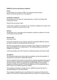
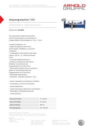
Photo: Intego GmbH<br />
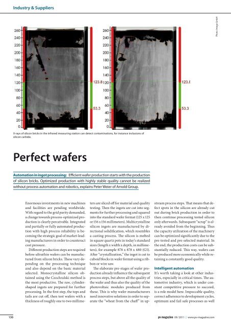
X-rays of silicon bricks in the infrared measuring station can detect contaminations, for instance inclusions of<br />
silicon carbide.<br />
<strong>Perfect</strong> <strong>wafers</strong><br />
Automation in ingot processing: Efficient wafer production starts with the production<br />
of silicon bricks. Optimized production with highly stable quality cannot be realized<br />
without process automation and robotics, explains Peter Weier of <strong>Arnold</strong> Group.<br />
Enormous investments in new machines<br />
and facilities are pending worldwide.<br />
With regard to the grid parity demanded,<br />
a change towards process-optimized production<br />
is clearly perceivable. Integrated<br />
and partially or fully automated production<br />
with high process reliability is becoming<br />
the strategic goal of market-leading<br />
manufacturers in order to counteract<br />
cost pressure.<br />
Different production steps are required<br />
before ultrathin <strong>wafers</strong> can be manufactured<br />
from silicon bricks. These vary depending<br />
on the processing technique<br />
and also depend on the basic material<br />
selected. Monocrystalline silicon obtained<br />
using the Czochralski method is<br />
the most productive. The raw, cylindershaped<br />
ingots are prepared for further<br />
processing. In the first step, the tops and<br />
tails are cut off, then test <strong>wafers</strong> with a<br />
thickness of roughly one to two millimeters<br />
are sliced off for material and quality<br />
testing. Then the ingots are cut into segments<br />
for further processing and squared<br />
into the standard wafer format (125 x 125<br />
or 156 x 156 millimeters). Multicrystalline<br />
silicon ingots are manufactured by directional<br />
solidification, which resembles<br />
a casting process. The silicon is melted<br />
in square quartz pots in today’s standard<br />
sizes (length x width x depth, in millimeters),<br />
for example 878 x 878 x 480 (G5).<br />
After “crystallization,” the ingot is cut to<br />
cuboid blocks in wafer format using a ribbon<br />
or wire saw.<br />
The elaborate pre-stages of wafer production<br />
already influence the subsequent<br />
process steps, but above all the quality of<br />
the wafer and thus also the quality of the<br />
photovoltaic modules produced from<br />
these. This is why wafer manufacturers<br />
need innovative solutions in order to separate<br />
the “wheat from the chaff” in upstream<br />
process steps. That means that defect<br />
spots in the silicon are already cut<br />
out during brick production in order to<br />
then continue processing tested silicon<br />
only afterwards. Subsequent “scrap” is already<br />
avoided from the beginning. Thus<br />
the capacity utilization of the machinery<br />
can be optimized significantly due to the<br />
pre-tested and pre-selected material. In<br />
the end, the production costs can be substantially<br />
reduced. This way, <strong>wafers</strong> can<br />
be produced more economically while retaining<br />
a constantly good quality.<br />
Intelligent automation<br />
It’s worth taking a look at other industries,<br />
especially in critical times. The automotive<br />
industry, which is under constant<br />
competitive pressure to succeed,<br />
is a role model here. Impeccable quality,<br />
correct adherence to development cycles,<br />
optimum and fail safe processes as well<br />
130<br />
09 / 2011 | www.pv-magazine.com
Industry & Suppliers<br />
as punctual delivery in accordance with<br />
the “just in time” principles guarantee<br />
the success. Suppliers are demanded to<br />
offer “zero error” strategies.<br />
Back to photovoltaics. Without a similar<br />
high degree of automation, comparable<br />
goals cannot be achieved in this industry.<br />
However, automation not only<br />
means including robots in partial processes,<br />
but much more. Each machine<br />
must not only provide high process reliability,<br />
but also a sophisticated sensor<br />
technology, highly intelligent control<br />
technology and interfaces to the periphery,<br />
as for example to the manufacturing<br />
execution system (MES).<br />
The substantial advantages for brick<br />
manufacturers become apparent when<br />
we take the example of a fully automated<br />
production line involving cutting (sawing)<br />
and gluing multi-crystalline bricks.<br />
Three centers aligned in series are connected<br />
with a conveyor belt. An industrial<br />
robot is placed centrally in each<br />
center. The communication between<br />
the machine control and the robot takes<br />
place via a superordinate production and<br />
quality control system (PQS).<br />
Before a brick is processed through<br />
the fully automated production line, it<br />
receives an identification number. This<br />
makes it possible to allocate each produced<br />
brick the corresponding process<br />
and measuring data.<br />
Efficient grinding<br />
The grinding center features surface<br />
grinding and chamfering machines<br />
aligned in a semicircle towards the conveyor.<br />
The robot takes the brick off the<br />
conveyor belt and places it into an available<br />
surface grinding machine. The centering<br />
device integrated in the machine<br />
centers the workpiece axis automatically<br />
to the machine axis. The workpiece is<br />
clamped and measured by a laser system.<br />
The grinding disks are paced automatically<br />
on the basis of the recorded measuring<br />
data. After simultaneous course<br />
grinding of two facing sides of the brick,<br />
the same sides pass through fine grinding.<br />
Then the bricks are measured for a<br />
second time for immediate inspection<br />
and documentation of the production<br />
quality. Turned by the robot, the workpiece<br />
is also course and fine ground on<br />
the other two sides using the previously<br />
described work steps. After the grinding<br />
work on the parallel surfaces is finished,<br />
the robot picks up the brick and inserts it<br />
in the chamfering machine. With a 45 degree<br />
turn, it puts the brick into the right<br />
position for chamfering. First, two 45 degree<br />
edges are chamfered, and after a 90<br />
degree angle turn by the robot the other<br />
two edges. The production quality prior<br />
and after processing is completely documented<br />
by measuring systems located inside<br />
the machine.<br />
Constant tracing<br />
Once the grinding process is completed,<br />
the robot transports the brick to the infrared<br />
(IR) measuring station. Every single<br />
brick is x-rayed in order to detect<br />
contamination like inclusions of silicon<br />
carbide, for example, at this time already.<br />
Directly after IR measuring, integrated<br />
service life and resistance measurement<br />
takes place on the conveyor belt. The<br />
quality of the bricks is checked extensively<br />
at this point. Any contamination<br />
reduces the service life of the semicon-
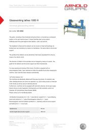
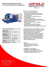
Industry & Suppliers<br />
A fully automated production line for multicrystalline silicon bricks, with grinding, cutting (sawing) and gluing center.<br />
ductor material silicon. The applied microwave<br />
PCD technology (µ-PCD measuring<br />
technique) operates at very high<br />
injections with a very short light pulse<br />
of approximately 200 nanoseconds.<br />
The photoconductivity is detected with<br />
the reflection of a microwave. Bricks in<br />
which, for example, no inclusions were<br />
detected in infrared measuring may still<br />
contain contamination in the form of<br />
heavy metals, crystallization effects and/<br />
or concentrations of iron. The quality of<br />
the affected brick is only partially impeccable<br />
in case of detected damage.<br />
Based on the results of all previous geometry<br />
and quality tests, the system automatically<br />
calculates which parts are flawless<br />
and which will have to be cut out in<br />
the downstream cropping center. This<br />
way, only the “good parts” of the brick<br />
are processed further.<br />
That leads to a substantial improvement<br />
of the material balance due to savings<br />
in silicon consumption. If such extensive<br />
measuring operations are not<br />
performed, possible wire cracks and<br />
substantial quality problems with a high<br />
scrap rate are inevitable.<br />
Photo: <strong>Arnold</strong> Group<br />
Precise cut<br />
Back to the production line. Before the<br />
brick enters the cutting center via the<br />
conveyor, the identification number is<br />
scanned again in order to record the subsequent<br />
steps comprehensively. The automatically<br />
generated calculations of the<br />
previous geometry, infrared and µ-PCD<br />
technique measurements are also used for<br />
cutting via the identification number.<br />
In the fully automatic cutting center,<br />
the brick is cut using the single-cut<br />
method based on the previous calculations.<br />
This gives the robot the chance to<br />
position each brick exactly as specified for<br />
the individual cutting steps. The cutting<br />
saws are aligned longitudinal to a linear<br />
traverse axis in the cutting center. The<br />
robot takes the individually transported<br />
bricks off the conveyor belt and places<br />
them directly in one of the outer diameter<br />
(OD) saws for cutting (also called cropping<br />
or cap cut). This denotes the cutting<br />
off of the top and bottom layer and/or the<br />
cutting of SIC (silicon carbide) inclusions<br />
in the silicon material of the bricks. The<br />
robot takes the sections out of the saw<br />
and gives them a consecutive identification<br />
number. While each part has its<br />
own identification number in the automotive<br />
industry, for example, the identification<br />
number of a brick remains with<br />
the corresponding additional characters<br />
in brick production, independent of how<br />
many individual parts are produced from<br />
a brick. This allows later continuous tracing<br />
of which part belongs to what brick.<br />
The brick is taken out of the saw and the<br />
“good parts” placed on the conveyor belt.<br />
End pieces or sections are placed separately<br />
on a lateral conveyor belt system.<br />
Due to contamination or reduced conductivity,<br />
the end pieces are not directly<br />
suited for further processing into <strong>wafers</strong>,<br />
but may partially be added to the crystallization<br />
process again after a recycling<br />
process. This efficient use of the material<br />
leads to substantial savings in the overall<br />
material balance.<br />
The applied thin blade cutting technique<br />
is based on the traditional circular<br />
OD sawing blade technology. In contrast<br />
to the standard blade strengths of<br />
3.5 millimeters, however, these saws are<br />
equipped with slim 1.5 millimeter saw<br />
blades for approximately 10,000 to 15,000<br />
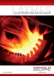
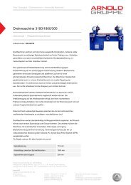
Photo: <strong>Arnold</strong> Group Photo: <strong>Arnold</strong> Group<br />
Measuring protocol (grinding) without process optimization (left) and with process optimization (right).<br />
132<br />
09 / 2011 | www.pv-magazine.com
Industry & Suppliers<br />
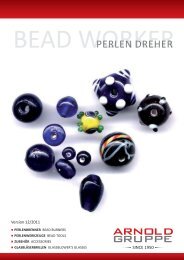
Photo: <strong>Arnold</strong> Group<br />
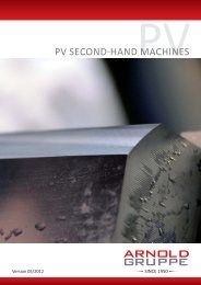
Sawing: a fluid-borne cutting disk in thin sheet technology.<br />
cuts. The silicon loss is thus reduced by<br />
around 50 percent. Among the advantages<br />
of this sawing technique are not<br />
only low consumption, maintenance and<br />
repair costs, but also an extremely high<br />
process stability and a just as high machine<br />
availability. The savings potential<br />
compared to other sawing techniques is<br />
around 80 percent.<br />
Exact gluing<br />
In the gluing center, the robot picks the<br />
silicon bricks off the conveyor belt and<br />
places them in the storing shelf. For optimized<br />
wire field utilization, the PQS system<br />
has already automatically calculated<br />
the individual brick lengths to a gluing<br />
batch. In the next step, the robot prepares<br />
the gluing process. First, the workpiece<br />
carriers are placed on a work slab; then<br />
glue is applied to the glass plates by the<br />
dosage system and these are then placed<br />
on the metal workpiece carriers. Now<br />
the robot gets the brick off the shelf and<br />
cleans it in the cleaning facility. Then the<br />
brick receives a strand of glue and placed<br />
on the glass plate.<br />
Gluing as a preliminary stage in wafer<br />
production is highly important. Around<br />
90 percent of this gluing work is still performed<br />
manually in the industry. This<br />
individualized process thus greatly depends<br />
on the individual worker. The glue<br />
demand in the automated gluing process<br />
can be reduced by at least 30 percent compared<br />
to the manual one. When using<br />
larger containers instead of smaller cartridges,<br />
further substantial savings are<br />
possible in the fully automated gluing<br />
section. Many manufacturers are still far<br />
from standardization. This is why there is<br />
still a very high error quota, especially in<br />
this sector. Every small error can drastically<br />
increase the break rate, whether<br />
during wafering or subsequent degluing.<br />
Some manufacturers try to achieve a certain<br />
uniformity in the gluing process by<br />
limiting the staff to just a few. But only<br />
the standardization of the gluing process<br />
through automation can perceivably<br />
lower the break rate of <strong>wafers</strong> and the associated<br />
costs.<br />
High availability<br />
All the cells of the production line each<br />
have their own safety zone. In the grinding<br />
and cutting center, only the work radius<br />
of the robot is surrounded by a safety<br />
fence. This way, all grinding, chamfering<br />
and cutting machines are located outside<br />
of the safety fence and are equipped with<br />
an additional safety gate. Maintenance<br />
and repair work like tool exchanges can<br />
therefore be performed at any time after<br />
closing the respective safety gate and access<br />
to the facility is unrestricted. All<br />
other machines are still in fully automatic<br />
operation in the entire process<br />
chain. This ensures the high availability<br />
of the production line.<br />
The author<br />
Peter Weier heads the Business Unit Silicon of <strong>Arnold</strong> Group,<br />
Weilburg, Germany. <strong>Arnold</strong> Group offers process and automation<br />
technology for the broad spectrum of silicon brick processing by<br />
one source with the core competencies mechanical cutting, grinding<br />
and polishing. Weier has over 20 years of international project<br />
experience in the quartz glass and glass fiber industry. As of 1995,<br />
his focus has been on photovoltaics. He is substantially involved in<br />
the conceptual design, development and distribution of machines<br />
for glass, quartz glass and silicon processing.<br />
www.arnold-gruppe.de<br />
Photo: <strong>Arnold</strong> Group<br />
Continuous optimization<br />
There is a manual inspection place between<br />
the grinding/polishing center<br />
and the cropping center of the line. This<br />
is equipped with three monitors. From<br />
there, operators can access the individual<br />
process data and machine parameters<br />
of the entire line and make changes in<br />
line with quality demands. Arpat, a process<br />
analysis tool of the grinding and cutting<br />
machines with open interface to the<br />
superordinate MES, provides all machine<br />
134<br />
09 / 2011 | www.pv-magazine.com
Industry & Suppliers<br />
data. The tool records, analyses, saves and<br />
visualizes the individual processes and<br />
settings. Data from the service life and<br />
resistance measurements can be viewed<br />
on the second and third monitor.<br />
Fully automatic process cycles<br />
The core of the fully automated line is the<br />
internally developed process automation<br />
system of the grinding and cutting machines.<br />
The term “close loop process development”<br />
was created with the aim of<br />
securing and raising the high process<br />
stability. It means that current production<br />
and process data is collected, visualized<br />
and analyzed. Process parameters<br />
are changed with the help of this data in<br />
order to perform optimizations.<br />
Equipped with the process analysis<br />
tool, it is possible to collect and log data in<br />
the current process of the individual machines.<br />
Amongst other things, geometrical<br />
workpiece data, general customerrelated<br />
workpiece information, process<br />
parameters, machine status according to<br />
SEMI E10, and so on, is recorded and analyzed.<br />
With the help of intelligent software,<br />
the machines are capable of making<br />
automatic corrections like adjusting<br />
the grinding wheel. In case of deviations<br />
from measurements, e.g. due to external<br />
temperature influences, the process<br />
error compensation is performed automatically.<br />
With this extensive data recording, it<br />
is possible to achieve and maintain a very<br />
good process capability in the grinding<br />
process of less than 1.67 CpK with a tolerance<br />
of +/- 0.05 milimeters. The “zero<br />
error” strategy, meaning “almost zero<br />
scrap” can already be accommodated<br />
with these values.<br />
For the user, this systematic data analysis<br />
option is an excellent tool in order to<br />
continuously optimize and improve the<br />
process to increase his advantages over<br />
the competitor. Stable processes are also<br />
a requirement for a high degree of automation,<br />
but also for reproducible production<br />
quality.<br />
Securing competitiveness<br />
A manufacturer with a 250-megawatt capacity<br />
produces around 67,570,000 <strong>wafers</strong><br />
annually in a 24-hour operation. If for example<br />
the break rate is reduced from five<br />
to four percent through process automation<br />
and automatic handling, the scrap<br />
rate of around 3,380,000 <strong>wafers</strong> reduces<br />
by 680,000 to approximately 2,700,000<br />
<strong>wafers</strong> – an enormous saving every<br />
year, taking a unit price of roughly 2.00<br />
U.S. dollars per multi-crystalline wafer:<br />
around 1,360,000 U.S. dollars.<br />
Decisions for investment are foresighted<br />
corporate decisions. Not the individual<br />
investment price of a machine<br />
is decisive here, but the cost package of<br />
the entire investment and, above all, the<br />
total cost of ownership (TCO). Criteria of<br />
a well-adjusted overall package are technically<br />
well-engineered machines with<br />
fully automated processes, an automatic<br />
handling system and a quality data recording<br />
system. This creates equal, reproducible<br />
prerequisites with continuous<br />
repeat accuracy, standardization<br />
without manual influences and one hundred<br />
percent quality control in all production<br />
steps. The advantages of automation<br />
are only achieved with the decision<br />
for the right concept with the right manufacturing<br />
equipment that enables stable<br />
processing. u