Sustainability of Constructions - Towards a Better Built Environment
Sustainability of Constructions - Towards a Better Built Environment
Sustainability of Constructions - Towards a Better Built Environment

You also want an ePaper? Increase the reach of your titles
YUMPU automatically turns print PDFs into web optimized ePapers that Google loves.
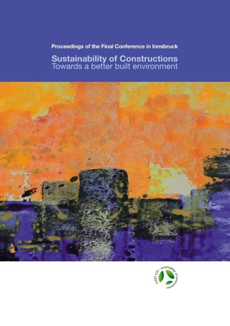
<strong>Sustainability</strong> <strong>of</strong> <strong>Constructions</strong><br />
<strong>Towards</strong> a <strong>Better</strong> <strong>Built</strong> <strong>Environment</strong><br />
Proceedings <strong>of</strong> the<br />
International Conference<br />
<strong>Sustainability</strong> <strong>of</strong> <strong>Constructions</strong><br />
<strong>Towards</strong> a <strong>Better</strong> <strong>Built</strong> <strong>Environment</strong><br />
Final Conference <strong>of</strong> the COST Action C25<br />
Innsbruck, 3-5 February 2011<br />
Editors:<br />
L. Bragança, H. Koukkari, R. Blok, H. Gervásio, M. Veljkovic,<br />
R.P. Borg, R. Landolfo, V. Ungureanu, C. Schaur<br />
COST is supported by the EU RTD Framework Programme and ESF provides the COST Office through an EC contract
COST - the acronym for European COoperation in Science and Technology - is the oldest and<br />
widest European intergovernmental network for cooperation in research. Established by the<br />
Ministerial Conference in November 1971, COST is presently used by the scientific<br />
communities <strong>of</strong> 36 European countries to cooperate in common research projects supported by<br />
national funds.<br />
The funds provided by COST - less than 1% <strong>of</strong> the total value <strong>of</strong> the projects - support the COST<br />
cooperation networks, COST Actions, through which, with only around € 20 million per year,<br />
more than 30.000 European scientists are involved in research having a total value which<br />
exceeds € 2 billion per year. This is the financial worth <strong>of</strong> the European added value which<br />
COST achieves.<br />
A “bottom up approach” (the initiative <strong>of</strong> launching a COST Action comes from the European<br />
scientists themselves), “à la carte participation” (only countries interested in the Action<br />
participate), “equality <strong>of</strong> access” (participation is open also to the scientific communities <strong>of</strong><br />
countries not belonging to the European Union) and “flexible structure” (easy implementation<br />
and light management <strong>of</strong> the research initiatives) are the main characteristics <strong>of</strong> COST.<br />
As precursor <strong>of</strong> advanced multidisciplinary research COST has a very important role for the<br />
realisation <strong>of</strong> the European Research Area (ERA) anticipating and complementing the activities<br />
<strong>of</strong> the Framework Programmes, constituting a “bridge” towards the scientific communities <strong>of</strong><br />
emerging countries, increasing the mobility <strong>of</strong> researchers across Europe and fostering the<br />
establishment <strong>of</strong> “Networks <strong>of</strong> Excellence” in many key scientific domains such as: Biomedicine<br />
and Molecular Biosciences; Food and Agriculture; Forests, their Products and Services;<br />
Materials, Physics and Nanosciences; Chemistry and Molecular Sciences and Technologies;<br />
Earth System Science and <strong>Environment</strong>al Management; Information and Communication<br />
Technologies; Transport and Urban Development; Individuals, Societies, Cultures and Health. It<br />
covers basic and more applied research and also addresses issues <strong>of</strong> pre-normative nature or <strong>of</strong><br />
societal importance.<br />
Proceedings <strong>of</strong> the International Conference<br />
<strong>Sustainability</strong> <strong>of</strong> <strong>Constructions</strong> - <strong>Towards</strong> a <strong>Better</strong> <strong>Built</strong> <strong>Environment</strong><br />
Final Conference <strong>of</strong> the COST Action C25<br />
<strong>Sustainability</strong> <strong>of</strong> <strong>Constructions</strong> - Integrated Approach to Life-time Structural Engineering<br />
Innsbruck, 3-5 February 2011<br />
Editors: Luís Bragança, Heli Koukkari, Rijk Blok, Helena Gervásio, Milan Veljkovic,<br />
Ruben Paul Borg, Raffaele Landolfo, Viorel Ungureanu, Christian Schaur<br />
Cover Design: Bogdan Oprescu<br />
Cover illustration is based on a painting <strong>of</strong> Gerda Medinaceli.<br />
The production <strong>of</strong> this publication was supported by COST: www.cost.eu<br />
ISBN: 978-99957-816-0-6<br />
© 2011 The authors and the Editors<br />
All rights reserved. No part <strong>of</strong> this book may be reproduced, stored in a retrieval system, or transmitted, in any form<br />
or by any means, without prior written permission from the publisher.<br />
LEGAL NOTICE<br />
The Editors, the Authors and the publisher are not responsible for the use which might be made <strong>of</strong> the following<br />
information.<br />
Published by: Department <strong>of</strong> Civil & Structural Engineering,<br />
Faculty for the <strong>Built</strong> <strong>Environment</strong>,<br />
University <strong>of</strong> Malta, Malta.<br />
Printed by Gutenberg Press Ltd, Malta.<br />
February 2011
Contents<br />
Foreword<br />
Luís Bragança, Heli Koukkari, Rijk Blok, Helena Gervásio, Milan Veljkovic,<br />
Ruben Paul Borg, Raffaele Landolfo, Viorel Ungureanu, Christian Schaur<br />
ix<br />
European Lead Market Initiative and Sustainable Construction 1<br />
Frank Schultmann, Michael Hiete and Anna Kühlen<br />
Politics for sustainable development – key documents 9<br />
Daniel Grecea and Mirela Szitar<br />
<strong>Sustainability</strong> <strong>of</strong> the urban planning <strong>of</strong> the Fortress (Cetate) neighborhood<br />
from Timisoara - how can 3D models help us to understand the historic<br />
evolution <strong>of</strong> the City 17<br />
Valentin Capotescu<br />
<strong>Sustainability</strong>: The new principle <strong>of</strong> Urban Rehabilitation in Portugal 25<br />
Ana Lídia Virtudes<br />
Mechanical Behaviour and Life Cycle Assessment <strong>of</strong> Fibre-Reinforced Timber Pr<strong>of</strong>iles 29<br />
Andreas Heiduschke, Peer Haller, Christian Manthey<br />
and Edeltraud Günther<br />
Effect <strong>of</strong> Mineral Admixtures on the Compressive Strength <strong>of</strong> Green Concrete with<br />
Coarse Recycled Aggregate 37<br />
Mirjana Malesev, Vlastimir Radonjanin, Snezana Marinkovic<br />
and Ali Emhemd Saed Al Malty<br />
Utilization <strong>of</strong> subtle structures from high performance concrete - contribution to<br />
sustainable building 45<br />
P. Hájek, M. Kynčlová and C. Fiala<br />
Wood Wool Cement Boards – solutions for sustainable buildings 53<br />
Peter E. Leewis<br />
Recycled Materials for Technical-Artistic Applications obtained with Tungsten<br />
Mine Coarse Wastes 63<br />
João Castro-Gomes, Abílio P. Silva, Rafael P. Cano and A. Durán Suarez<br />
Eco-Efficient Ternary Mixtures Incorporating Fly Ash and Metakaolin 71<br />
Rui Reis and Aires Camões<br />
Spent Catalyst Cracking Waste: pozzolanic activity and its influence on cement<br />
paste and mortars properties 79<br />
Sayonara Maria de Moraes Pinheiro and Gladis Camarini<br />
Formulation <strong>of</strong> Efficient Silicate Disperse Paints 87<br />
Marijonas Daunoravičius, Edita Smetonaitė and Rosita Norvaišienė<br />
Iron, Steel and Stainless Steel, from the Point <strong>of</strong> Eco-Efficient Materials and Technologies 97<br />
Yesim Kamile Aktuglu<br />
iii
Earth material and buildings: sustainable constructions techniques 103<br />
Silvia Briccoli Bati and Elena Cinquina<br />
Properties <strong>of</strong> Geopolymeric Artificial Aggregates obtained from Tungsten Mine<br />
Waste Mud, for Wastewater Treatment Processes 111<br />
Isabel Silva, João Castro-Gomes and António Albuquerque<br />
Embodied energy optimization by innovative structural systems 117<br />
Matthias Braun, Oliver Hechler, Gunter Hauf and Ulrike Kuhlmann<br />
Development <strong>of</strong> a Universal Scissor Component (USC) for Temporary Structures 125<br />
Lara Alegria Mira and Niels De Temmerman<br />
Aiming at <strong>Sustainability</strong> through Multi-layering for the Cyprus News Agency<br />
Building Proposal 133<br />
Paris Fokaides, Marios C. Phocas and Nadia Charalambous<br />
Improving the seismic behavior <strong>of</strong> architectural glazing 141<br />
Roham Afghanikhorasgani, Tiziana Poli and Maria Adelaide Parisi<br />
Innovative Technologies for Sustainable Houses with Steel 147<br />
Yesim Kamile Aktuglu<br />
Sustainable building assessment tools and the quality <strong>of</strong> the built environment 155<br />
Mirela Szitar and Daniel Grecea<br />
Analysis <strong>of</strong> the impacts <strong>of</strong> economic and social indicators to sustainability assessment 163<br />
Joana B. Andrade and Luís Bragança<br />
Examination <strong>of</strong> Turkish House in the Context <strong>of</strong> <strong>Sustainability</strong> 169<br />
Mine Tanaç Zeren<br />
Role <strong>of</strong> Codes for <strong>Sustainability</strong> Assessment <strong>of</strong> <strong>Constructions</strong> 175<br />
Violeta Nushi and Ferhat Bejtullahu<br />
How Durability is considered in <strong>Sustainability</strong> Codes 183<br />
Bruno Daniotti and Reza Raeis Samiei<br />
Standards for <strong>Sustainability</strong> Assessment <strong>of</strong> Construction Works 189<br />
António Baio Dias and Ari Ilomäki<br />
Improving the Design <strong>of</strong> a Residential Building Using the Portuguese Rating<br />
System SBToolPT 197<br />
Luis Bragança and Ricardo Mateus<br />
Development <strong>of</strong> a sustainability assessment tool for <strong>of</strong>fice buildings 205<br />
José Amarilio Barbosa, Ricardo Mateus and Luís Bragança<br />
Selecting <strong>Environment</strong>al Friendly Alternatives in Infrastructure Projects 215<br />
Fernando Rodríguez López and Gonzalo Fernández Sánchez<br />
Czech assessment system SBToolCZ 221<br />
Antonín Lupíšek, Martin Vonka and Petr Hájek<br />
iv
<strong>Sustainability</strong> assessment <strong>of</strong> buildings and needs <strong>of</strong> stakeholders 225<br />
Antonín Lupíšek, Tarja Häkkinen, Petr Hájek and Tereza Pavlů<br />
Comparison <strong>of</strong> Eco-Office Buildings from the Viewpoint <strong>of</strong> <strong>Sustainability</strong> <strong>of</strong><br />
<strong>Constructions</strong> 229<br />
A. Vefa Orhon and Mujde Altin<br />
Integrated design <strong>of</strong> buildings 235<br />
Adrian Ciutina, Viorel Ungureanu, Dan Dubina and Florea Dinu<br />
Building sustainability theory meets practice; Opportunities and gaps: the case <strong>of</strong> GPP<br />
and examples from Slovenia and Greece 247<br />
M. Sijanec-Zavrl and C. Giarma<br />
Life-Cycle Assessment <strong>of</strong> Residential Buildings 255<br />
Ricardo Mateus and Luís Bragança<br />
LCA <strong>of</strong> building envelope components - Part 1. A database for Greece 263<br />
C. Giarma, D. Bikas and K. J. Kontoleon<br />
LCA <strong>of</strong> building envelope components - Part 2. The computational tool BEnICa 271<br />
C. Giarma, D. Bikas and K. J. Kontoleon<br />
Life Cycle Impacts Assessment <strong>of</strong><br />
Steel, Composite, Concrete and Wooden Columns 277<br />
Barbara Rossi, Ivan Lukic, Naveed Iqbal, GuangLi Du, Diarmuid Cregg<br />
Ruben Paul Borg and Peer Haller<br />
<strong>Environment</strong>al Performance <strong>of</strong> Contemporary Multi-storey Timber Buildings 285<br />
Yu-hsiang Yeh and Peer Haller<br />
Comparative Study <strong>of</strong> the Life Cycle Pr<strong>of</strong>ile <strong>of</strong> Residential Masonry and Steel<br />
Framed Buildings in Belgium 295<br />
Ligia Massetto de Aquino, Sigrid Reiter and Barbara Rossi<br />
Life-cycle assessment <strong>of</strong> thermal insulation materials for external walls <strong>of</strong> buildings 303<br />
J. D. Silvestre, J. de Brito and M. D. Pinheiro<br />
Life Cycle Assessment <strong>of</strong> building structure 311<br />
Michele Paleari, Andrea Campioli and Monica Lavagna<br />
Life cycle inventory (LCI) <strong>of</strong> cold-formed hollow structural steel sections for the<br />
sustainability assessment <strong>of</strong> metal structures 317<br />
Iordanis Zygomalas, Evangelos Efthymiou and<br />
Charalambos C. Baniotopoulos<br />
The use <strong>of</strong> cold formed steel systems for sustainable emergency housing:<br />
Application <strong>of</strong> LCA methodology to a modular construction 325<br />
Ornella Iuorio, Caterina Antonia Dattilo, Gianmaria Di Lorenzo and<br />
Raffaele Landolfo<br />
<strong>Environment</strong>al impact assessment <strong>of</strong> steel residential buildings 333<br />
Öget N. Cöcen, Iordanis Zygomalas and Evangelos Efthymiou<br />
v
Life cycle analysis <strong>of</strong> a steel framed building in Romania 341<br />
Viorel Ungureanu, Adrian Ciutina and Dan Dubina<br />
<strong>Environment</strong>al Product Declaration for structural steel as basis for sustainability<br />
assessment <strong>of</strong> constructions 351<br />
Bernhard Hauke, Oliver Hechler, Georges Axmann and Diana Fischer<br />
Life Cycle Assessment <strong>of</strong> Composite Bridges 361<br />
Anne-Laure Hettinger, Jean-Sebastien Thomas, Oliver Hechler and Yves Conan<br />
Sustainable Steel-Composite Bridges 373<br />
Ulrike Kuhlmann and Philippa Maier<br />
Life cycle assessment for railway bridge infrastructure:<br />
a case study <strong>of</strong> Bollstaån Bridge 381<br />
Guangli Du<br />
Adaptation to Climate Change in Finnish Concrete Buildings - Preliminary Study 387<br />
Jukka Lahdensivu and Hanna Tietäväinen<br />
Climate change effects on the robustness <strong>of</strong> building stock 395<br />
Dan Dubina and Florea Dinu<br />
<strong>Environment</strong>al expenditures <strong>of</strong> households 401<br />
M. Broniewicz and Y. K. Aktuglu<br />
Effects <strong>of</strong> wall’s masonry-density on decrement factor & time lag 409<br />
Karolos J. Kontoleon, Dimitrios K. Bikas and Christina St. Giarma<br />
Examination <strong>of</strong> Shading-Photovoltaic Building Components from the Viewpoint <strong>of</strong><br />
<strong>Sustainability</strong> 417<br />
Mujde Altin<br />
Façade Modules for Eco-Efficient Refurbishment <strong>of</strong> Buildings: Glazing Thermal<br />
Performance to Guimarães Climate 423<br />
Helenice M. Sacht, Luís Bragança and Manuela Almeida<br />
Energy Efficient Design Support Systems: a case-based probabilistic approach 431<br />
Alberto Giretti, Roberta Ansuini, Massimo Lemma and Roberto Larghetti<br />
The Requirements and Testing <strong>of</strong> Frost Durability <strong>of</strong> ETICS 439<br />
Toni Pakkala, Jommi Suonketo and Jukka Lahdensivu<br />
Converting a conventional residential building into a sustainable one 447<br />
Niki Asimi, Artemis Safouri and Georgia Safouri<br />
From the Traditional Architecture, throughout the Formula, to the Design Guidelines:<br />
the Wind Tower Tradition 455<br />
Cristina Benedetti, Giuliana Leone, Marco Baratieri and Ilaria Brauer<br />
Evaluation <strong>of</strong> the impact <strong>of</strong> some Portuguese thermal regulation parameters<br />
on the buildings energy performance 463<br />
Catarina Araújo, Manuela Almeida and Luís Bragança<br />
vi
New Performing Art Centers <strong>of</strong> the World and <strong>Sustainability</strong> Concept 471<br />
Ozgul Yilmaz Karaman<br />
Monitoring <strong>of</strong> a close-to-zero energy building 477<br />
Tamás Csoknyai and Attila Talamon<br />
<strong>Sustainability</strong> Assessment <strong>of</strong> a Multistorey Steel Structure Located in a Seismic Area 485<br />
Mircea Georgescu and Viorel Ungureanu<br />
A new approach to energetic requalification <strong>of</strong> existing buildings 493<br />
Cristina Benedetti, Martina Demattio and Maria Teresa Girasoli<br />
Renovation <strong>of</strong> façades: environmental and energy issues 501<br />
Leonardo Marques Monteiro and Anésia Barros Frota<br />
Solutions for thermal renovation <strong>of</strong> precast concrete wall panels – Case study 509<br />
Iulia Tuca, Dan Dubina, Adrian Ciutina and Viorel Ungureanu<br />
Maintenance and retr<strong>of</strong>itting measures for a monumental building in the Vesuvius area 519<br />
Gilda Florio, Raffaele Landolfo, Antonio Formisano and Federico M. Mazzolani<br />
Sustainable Conservation Methods <strong>of</strong> Improvement and Structural<br />
Strengthening <strong>of</strong> Old Timber Elements <strong>of</strong> Traditional Turkish Houses 527<br />
Mine Tanaç Zeren<br />
Sustainable Restoration <strong>of</strong> the Ro<strong>of</strong> <strong>of</strong> a Large Indoor Pool 535<br />
Hartmut Pasternak<br />
Building envelope rehabilitation costs variability 543<br />
Carina Sousa and João Lanzinha<br />
Rehabilitation Strategy: Sustainable Development Centre, Malta 551<br />
Ruben Paul Borg and Cyril Spiteri Staines<br />
The engineering <strong>of</strong> the prehistoric megalithic temples in Malta 559<br />
Alex Torpiano<br />
Scenarios for our common built environment 571<br />
Heli Koukkari<br />
Author Index 581<br />
vii
viii
Foreword<br />
The built environment has evolved to frame and facilitate nearly all human activities.<br />
Simultaneously, its constant expansion has become more and more harmful to the natural<br />
environment. In order to turn the global trends toward the optimistic transition scenario <strong>of</strong> the<br />
sustainable development, the built environment needs to be rethought. The construction and<br />
building sector play a key role in creation the better future.<br />
In 1999, CIB - International Council for Research and Innovation in Building and Construction,<br />
adopted the goal <strong>of</strong> sustainable construction as “…creating and operating a healthy built<br />
environment based on resource efficiency and ecological principles” and later on articulated the<br />
7 Principles <strong>of</strong> Sustainable Construction: 1) Reduce resource consumption; 2) Reuse resources;<br />
3) Use recyclable resources; 4) Protect nature; 5) Eliminate toxics; 6) Apply life-cycle costing<br />
and 7) Focus on quality. The sustainable construction involves ways and means to implement<br />
life-cycle thinking in the built environment. In the early stages <strong>of</strong> the concept development, the<br />
environmental impacts were emphasised but the social, economic and cultural aspects <strong>of</strong><br />
sustainable development are regarded as important nowadays.<br />
This publication is the Proceedings <strong>of</strong> the Final Conference <strong>of</strong> the COST Action C25, opened to<br />
the public under the theme “<strong>Sustainability</strong> <strong>of</strong> <strong>Constructions</strong> - <strong>Towards</strong> a better built<br />
environment”. The Action C25 “<strong>Sustainability</strong> <strong>of</strong> <strong>Constructions</strong> - Integrated Approach to Lifetime<br />
Structural Engineering” was established to promote science- and research-based<br />
approaches for life-cycle building technologies. It is one prominent landmark <strong>of</strong> a worldwide<br />
movement aiming at knowledge creation and dissemination in the field <strong>of</strong> sustainable<br />
construction. The amount <strong>of</strong> researchers, stakeholders and practitioners conscious <strong>of</strong><br />
sustainability has grown from some tens <strong>of</strong> pioneers to tens <strong>of</strong> thousands. The methods <strong>of</strong><br />
sustainable architecture and life-time engineering are been developed and implemented more<br />
<strong>of</strong>ten as a part <strong>of</strong> everyday practices. Several international networks and organisations have<br />
been organised in order to promote the sustainable construction like e.g. the International<br />
Initiative for a Sustainable <strong>Built</strong> <strong>Environment</strong> (iiSBE) and the International Association for Life<br />
Cycle Civil Engineering (IALCCE).<br />
The Kick-<strong>of</strong>f Meeting <strong>of</strong> the Action C25 was held on the 3 rd <strong>of</strong> October 2006 in Brussels. In<br />
total, 28 countries (Austria, Belgium, Bulgaria, Croatia, Czech Republic, Cyprus, Denmark,<br />
Finland, fyr Macedonia, Germany, Greece, Hungary, Italy, Latvia, Lithuania, Luxembourg,<br />
Malta, The Netherlands, Norway, Poland, Portugal, Romania, Serbia, Slovenia, Sweden,<br />
Switzerland, Turkey and The United Kingdom) and one EC Joint Research Centre joined this<br />
network. The participating countries nominated almost one hundred Management Committee<br />
(MC) delegates and Working Group (WG) members, which represent different fields <strong>of</strong><br />
expertise, different cultures, different approaches and different visions <strong>of</strong> the society and the<br />
world. Ten Management Committee meetings have been organised in nine COST countries<br />
during the course <strong>of</strong> four years that the Action was active.<br />
These Proceedings cover a wide range <strong>of</strong> up-to-date issues that reflect research in the<br />
participating countries in the field <strong>of</strong> sustainable constructions. The issues presented include:<br />
Eco-efficient materials and technologies<br />
Innovative construction systems<br />
<strong>Sustainability</strong> Assessment <strong>of</strong> <strong>Constructions</strong><br />
Adaptation to Climate Change<br />
Design and Technologies for Energy Efficiency<br />
Life-time structural engineering<br />
Maintenance and Monitoring<br />
Renovation and Retr<strong>of</strong>itting<br />
Policy for sustainable development<br />
ix
The Organizing Committee wants to warmly thank all the keynote speakers and authors <strong>of</strong><br />
conference papers. Their efforts reflect their commitment and dedication to Science and<br />
Sustainable Construction. The conference received more than one hundred abstracts and after<br />
the revision process about 75% were accepted to be published. About half <strong>of</strong> the papers are<br />
from non-C25 members which denote the public interest on the conference.<br />
A special gratitude is also addressed to Dr. Thierry Goger and Ms. Carmencita Malimban from<br />
COST Office and ESF (European Science Foundation) for their support and help in<br />
administrative matters.<br />
This publication represents one more important milestone in fulfilment <strong>of</strong> the main aims <strong>of</strong> the<br />
COST Action C25. The organisers <strong>of</strong> the conference hope that it will inspire all participants to<br />
work for changing the trends <strong>of</strong> construction sector and use <strong>of</strong> the built environment.<br />
The Action Chairs and Proceedings Editors<br />
Luís Bragança (University <strong>of</strong> Minho, Portugal)<br />
Heli Koukkari (VTT Technical Research Centre, Finland)<br />
Rijk Blok (University <strong>of</strong> Technology Eindhoven, The Netherlands)<br />
Helena Gervásio (University <strong>of</strong> Coimbra, Portugal)<br />
Milan Veljkovic (Luleå University <strong>of</strong> Technology, Sweden)<br />
Zbigniew Plewako (Rzeszów University <strong>of</strong> Technology, Poland)<br />
Raffaele Landolfo (University <strong>of</strong> Naples “Federico II”, Italy)<br />
Viorel Ungureanu (Politehnica University <strong>of</strong> Timisoara, Romania)<br />
Ruben Paul Borg (University <strong>of</strong> Malta, Malta)<br />
Christian Schaur (Schaur ZTGmbH)<br />
COST Action C25 Webpage: www.cmm.pt/costc25/<br />
x
International Conference <strong>Sustainability</strong> <strong>of</strong> <strong>Constructions</strong> - <strong>Towards</strong> a better built environment<br />
______________________________________________________________________________________________________<br />
European Lead Market Initiative and Sustainable Construction<br />
Frank Schultmann<br />
KIT - Karlsruhe Institute <strong>of</strong> Technology, Institute for Industrial Production (IIP) & French-German<br />
Institute for <strong>Environment</strong>al Research (DFIU), Karlsruhe, Germany<br />
frank.schultmann@kit.edu<br />
Michael Hiete<br />
KIT - Karlsruhe Institute <strong>of</strong> Technology, French-German Institute for <strong>Environment</strong>al Research (DFIU),<br />
Karlsruhe, Germany<br />
michael.hiete@kit.edu<br />
Anna Kühlen<br />
KIT - Karlsruhe Institute <strong>of</strong> Technology, French-German Institute for <strong>Environment</strong>al Research (DFIU),<br />
Karlsruhe, Germany<br />
anna.kuehlen@kit.edu<br />
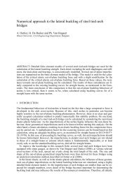
ABSTRACT: Sustainable Construction (SC) is one <strong>of</strong> six lead markets in the EU which have<br />
been selected for their high potential <strong>of</strong> innovation and market growth. Within the lead market<br />
initiative (LMI) for Europe individual action plans <strong>of</strong> 3-5 years were developed to support the<br />
lead markets by innovation-friendly and barrier-reducing policy instruments. One barrier is the<br />
high market fragmentation and high administrative costs due to uncoordinated regulation on<br />
different levels. Taking Germany as an example the framework for SC is analyzed with respect<br />
to public and private measures and initiatives. The establishment <strong>of</strong> a national strategy for SC<br />
coordinated on national level by a public central body is determined as one central element to<br />
reduce administrative burdens and to optimize and communicate initiatives and public research<br />
activities. To support SC a consistent national regulatory framework is essential, including<br />
functional, performance-based building related regulations, concentrating on certain objectives<br />
through the optimization <strong>of</strong> the planning process and by looking at the structure as a whole. A<br />
widening <strong>of</strong> the current approach which focuses strongly on energy efficiency, technical issues<br />
and construction products by social, cultural and aesthetic aspects and a more integrated approach<br />
are requested. A single national building evaluation system including LCA is been figured<br />
out as an important driving force for SC.<br />
1 INTRODUCTION<br />
Since the UN Conference on <strong>Environment</strong> and Development (UNCED) in Rio de Janeiro in<br />
1992, sustainable development has become popular worldwide with inter- and intragenerational<br />
equity (WCED 1987) and the simultaneous pursuit <strong>of</strong> economic, ecologic and social goals—<br />
<strong>of</strong>ten entitled as dimensions <strong>of</strong> sustainability—being the core <strong>of</strong> the concept. Buildings and<br />
construction play a key role in sustainable development for several reasons. Buildings have a<br />
service lifetime <strong>of</strong> <strong>of</strong>ten more than 100 years touching per se intergenerational aspect and<br />
throughout their entire lifecycle they show strong impacts and relationship with respect to all<br />
dimensions <strong>of</strong> sustainability. Consequently, interest in Sustainable Construction (SC) has increased<br />
considerably in recent years.<br />
The European Commission (EC) identified SC as one <strong>of</strong> six lead markets in the EU with high<br />
innovative and growth potential in the coming years. Through its lead market initiative (LMI)<br />
decided in 2007 the Commission intends to foster SC by a thematic and demand driven approach<br />
implementing a process to better streamline the legal and regulatory framework and to<br />
accelerate the growth in demand (EC 2007a). Faced challenges include the operationalization<br />
<strong>of</strong> SC and in particular the complexity <strong>of</strong> the topic. The rather recent concept <strong>of</strong> SC addresses<br />
numerous aspects <strong>of</strong> construction in an integrated way already covered before but under a different<br />
heading and in an isolated way leading to a highly complex and uncoordinated or even<br />
contradictory legal and regulatory framework at the regional, national and EU level. Furthermore,<br />
numerous public and private sector activities and initiatives have emerged.<br />
1
COST Action C25 - Final Conference<br />
______________________________________________________________________________________________________<br />
This contribution aims at providing an overview <strong>of</strong> the LMI and the existing framework for<br />
SC in the EU taking Germany as an example. A focus lies on regulation and standards as well<br />
as effective measures and initiatives for SC on national and EU level.<br />
2 THE EUROPEAN LEAD MARKET INITIATIVE<br />
2.1 The Initiative and the Lead Markets<br />
The lead market initiative (LMI) for Europe was developed by the European Commission (EC),<br />
the executive body <strong>of</strong> the EU, to enhance and secure the economic strength and competitiveness<br />
<strong>of</strong> the EU in emerging markets with a high innovative potential. In 2007 this broad innovationstrategy<br />
was decided with the aim to double the total volume <strong>of</strong> identified lead markets and to<br />
create one million new jobs in the EU by 2020 (EC 2007a). With the help <strong>of</strong> various policy instruments<br />
and measures, being the body <strong>of</strong> the LMI, the Commission wants to stimulate economic<br />
growth, to facilitate access to better goods and services and to increase employment (EC<br />
2007a). Overall six promising emerging markets were identified by the Commission as lead<br />
markets taking into account inter alia the market potential in the EU and worldwide on the<br />
short-term, the number and broadness <strong>of</strong> <strong>of</strong>fered products and services, benefits for the society,<br />
effectiveness <strong>of</strong> policy instruments and the risk <strong>of</strong> disturbing fair market competition (cf. EC<br />
2007c for details). This analysis and stakeholder consultations led to the identification <strong>of</strong> SC as<br />
well as eHealth, protective textiles, recycling, bio-based products and renewable energies as<br />
lead markets. For each lead market a 3 to 5 years action plan was developed comprising four<br />
groups <strong>of</strong> policy instruments/measures: i) legislation, ii) public procurement to increase demand,<br />
iii) standardization, certification, labeling and certification, and iv) complementary actions<br />
such as promotion, exchanges, and qualification etc. (EC 2007b).<br />
2.2 The EU Lead Market SC<br />
2.2.1 Characteristics <strong>of</strong> the EU Construction Sector<br />
The construction sector is <strong>of</strong> high economic relevance in the EU. It counted 3.1 million enterprises<br />
in the 27 member states in 2007 that together generated a combined value added <strong>of</strong> EUR<br />
562 billion (EUROSTAT 2010). This corresponds to 10.7% <strong>of</strong> the GDP and 51.5% <strong>of</strong> Gross<br />
Fixed Capital formation. With 14.8 million people employed it is also the largest industrial employer<br />
in the EU, providing 30% <strong>of</strong> the industrial employment. Among this workforce, only<br />
81.1% were paid employees, which reveals a relatively high rate <strong>of</strong> self-employment in the constructions<br />
sector. 92% <strong>of</strong> the EU construction enterprises were micro organizations, 7% small<br />
organizations with 10 to 49 employees, 1% with 50 to 249 employees, and only 0.2% large organizations.<br />
The construction sector and buildings account also for major environmental impacts in the<br />
EU. They demand for 42% <strong>of</strong> the total final energy and 50 wt. % <strong>of</strong> extracted materials (EC<br />
2007a; ECTP 2005). Furthermore, 35% <strong>of</strong> greenhouse emissions are connected to buildings and<br />
22 wt. % <strong>of</strong> waste generation.<br />
2.2.2 Sustainable Construction (SC)<br />
In SC all construction processes and products are regarded taking the three pillars <strong>of</strong> sustainability<br />
representing environmental, economical and socio-cultural issues into account. The longterm<br />
perspective <strong>of</strong> sustainability requires accounting for life-cycle aspects <strong>of</strong> buildings. The<br />
different aspects covered by SC like environmental impacts (e.g. emissions, resource consumption),<br />
health (e.g. in-door air-quality), well-being and comfort (e.g. accessibility for elderly<br />
people), life-cycle- and living-costs are not new. However, SC introduces an integrated and<br />
long-term point <strong>of</strong> view accounting for all the aspects simultaneously in a balanced way. All<br />
this makes SC a rather broad concept which is in practice difficult to tackle, as grown structures<br />
addressing different, sometimes inconsistent and fragmented areas each with its specific stakeholders<br />
have to be brought together and amended by missing parts to form the balanced and integrated<br />
point <strong>of</strong> view in line with SC.<br />
2
International Conference <strong>Sustainability</strong> <strong>of</strong> <strong>Constructions</strong> - <strong>Towards</strong> a better built environment<br />
______________________________________________________________________________________________________<br />
2.2.3 The Lead Market Initiative for SC<br />
In the EU the construction sector is typically characterized by predominantly local SMEs as<br />
well as various and diverse stakeholders. The local company structure in combination with extensive<br />
but at the same time fragmented and insufficiently coordinated national regulations<br />
leads to administrative burdens and a highly fragmented market structure hindering the development<br />
and diffusion <strong>of</strong> innovate solutions (EC 2007c).<br />
Within the LMI an action plan was developed and three working groups (WG) were installed:<br />
WG-1 for regulatory and standardisation framework, WG-2 for life cycle costing and<br />
public procurement, WG-3 for strategies for SC. Due to thematic overlap, WG-2 was closed<br />
meanwhile. The action plan comprises 11 fields <strong>of</strong> actions under 4 policy instruments (legislation,<br />
public procurement, standardization, labeling and certification as well as complementary<br />
actions) for the period 2008 to 2011. The actions include (EC 2007c; cf. EC 2009a for a midterm<br />
report): An analysis <strong>of</strong> the existing national legal frameworks aims at including building<br />
performance targets and standards in the frameworks and improving conditions for innovative<br />
solutions in the future. Guidance documents and pilot schemes are developed to strengthen life<br />
cycle costing in procurement. In the area standardization, labeling and certification, a framework<br />
for sustainability assessment <strong>of</strong> buildings is foreseen to make sustainable performance<br />
measurable on a voluntary basis, new standards are developed to integrate sustainability aspects<br />
in the design phase and getting European Technical Approval for innovative products is facilitated.<br />
Complementary actions aim at facilitating collaborative working, reducing liability barriers<br />
for innovative products and determining future qualification needs.<br />
3 FRAMEWORK FOR SC IN GERMANY<br />
3.1 General Legal Framework<br />
The legal framework for SC in Germany is rather complex for mainly two reasons. First, the<br />
concept <strong>of</strong> SC with its three pillars itself is broad and the number <strong>of</strong> addressed issues is high.<br />
Secondly, the legal framework for SC encompasses several levels: from the international and<br />
EU level, over the national and the federal state level down to the local level.<br />
International treaties like the UN Framework Convention on Climate Change (UNFCCC)<br />
(1992) with the Kyoto Protocol (1997) give a framework for national policy but are nonbinding<br />
for citizens or companies. Also directives like the Energy Performance <strong>of</strong> Buildings Directive<br />
(EPBD) must be implemented by national legislation. The advantage is that flexibility<br />
exists for the member states to integrate it in the best way into their legal framework, this, however,<br />
at the expense <strong>of</strong> differences in implementation between EU member states. EU regulations<br />
on the other hand are directly binding. In some areas like urban planning both a national<br />
law and a federal state ordinance for detailing exist. Another prominent example is the use <strong>of</strong><br />
renewable heat in buildings. The Renewable Energy Directive (2009/28/EC) was anticipated by<br />
the federal Renewable Energy Heat Act (REHA or EEWärmeG) which itself had a predecessor,<br />
the Renewable Heat Act (RHA or EWärmeG) <strong>of</strong> the federal state <strong>of</strong> Baden-Württemberg. RHA<br />
required both a minimum share <strong>of</strong> renewable heat in new and in existing buildings in case that<br />
the heating is exchanged. As federal law beats state law and REHA sets only minimum shares<br />
for new buildings, RHA is replaced by REHA for new buildings in the State <strong>of</strong> Baden-<br />
Württemberg but is still valid for existing ones. The legal framework is complemented by a<br />
number <strong>of</strong> technical standards and norms which can become compulsory if regulation refers to<br />
them.<br />
3.2 Laws, Regulations and Standards<br />
In June 2006 the European Council, i.e. the heads <strong>of</strong> state or government <strong>of</strong> EU member states<br />
along with the EU President and the President <strong>of</strong> the EC, adopted the Renewed Sustainable Development<br />
Strategy as an overall strategy for and a fundamental objective <strong>of</strong> EU policy. One<br />
key element <strong>of</strong> the strategy is sustainable consumption and production. The EC presented the<br />
corresponding action plan (SCP/SIP) in July 2008. The focus lies on the environmental performance<br />
<strong>of</strong> products and production technologies as well as on green public procurement (GPP),<br />
which has a great impact on activities within the construction industry (EC 2009b). The key EU<br />
3
COST Action C25 - Final Conference<br />
______________________________________________________________________________________________________<br />
directives for SC are the Construction Products Directive (CPD, 89/106/EEC) introducing European<br />
Technical Approval (ETA), i.e. a technical assessment <strong>of</strong> the fitness <strong>of</strong> a construction<br />
product for an intended use, and the Energy Performance <strong>of</strong> Buildings Directive (EPBD,<br />
2002/91/EC). The EPBD obliges member states to enhance their building regulations by energy<br />
efficiency requirements, to introduce energy certification schemes for buildings and to have inspections<br />
<strong>of</strong> boilers and air-conditioners. In general, EU legislation focuses on energy efficiency,<br />
whereas sustainability issues such as integrated planning, award <strong>of</strong> the most sustainable<br />
proposal, urban development and efficient land use, optimization during the use phase <strong>of</strong> a<br />
building, accessibility as well as deconstruction and recycling are little or not accounted for.<br />
In contrast, the German legal framework focuses on environmental aspects such as energy efficiency,<br />
renewable energies, environmental impacts, including emissions, waste generation and<br />
life cycle assessment <strong>of</strong> construction products as well as on social aspects, including barrierfree<br />
construction and thermal comfort. The focal life-cycle phases within the legal framework<br />
are the design and planning phase and the use phase. Integral planning and awarding based on<br />
sustainability criteria are, however, not and the construction and deconstruction phases barely<br />
covered.<br />
3.3 Measures and Initiatives<br />
3.3.1 National Strategy and Coordination<br />
The German federal government supports SC in various ways. A national strategy for SC was<br />
defined, coordinated centrally by the Federal Ministry <strong>of</strong> Transport, Building and Urban Development<br />
(BMVBS). The strategy is linked to the Integrated Energy and Climate Protection Program<br />
(IEKP) decided in 2007 by the German government and addresses renewable energy,<br />
energy efficiency, energy refurbishment, measurement and control <strong>of</strong> power consumption and<br />
calculation <strong>of</strong> operating costs <strong>of</strong> a building.<br />
3.3.2 Public Initiatives<br />
BMVBS established a national information platform for SC to publish and spread information<br />
about national and European measures and initiatives. Especially the activities <strong>of</strong> the LMI and<br />
<strong>of</strong> the round table for SC - an advisory board for the BMVBS with representatives <strong>of</strong> construction<br />
industry, associations, public authorities and research institutes - are presented. Additionally,<br />
guidelines for SC are downloadable which are compulsory for federal authorities.<br />
A national system for integrated assessment <strong>of</strong> building performance (BNB) was developed.<br />
It aims at measuring the sustainable performance <strong>of</strong> existing and planned buildings in an easy<br />
and transparent way. The system addresses all aspects <strong>of</strong> SC, such as environmental, economic,<br />
social-cultural, functional, technical, processes and location quality and with a special focus on<br />
life-cycle-assessment (LCA). The system - originally developed for <strong>of</strong>fice and administrative<br />
buildings - is further developed for other constructions. The system will become obligatory for<br />
the construction <strong>of</strong> federal buildings in mid 2010 in order to make them a model for SC<br />
(BMVBS 2010).<br />
3.3.3 Private Initiatives<br />
Besides public initiatives also industry supports research, development and the dissemination <strong>of</strong><br />
SC and related products, for instance the steel and concrete industry. Initiatives <strong>of</strong> manufacturers<br />
<strong>of</strong> construction products promote and develop environmental product declarations (EPD)<br />
for building materials and products (IBU 2010).<br />
Besides the governmental building evaluation system (BNB), also private building certification<br />
systems are developed, such as the Certification system <strong>of</strong> the German Sustainable Building<br />
Council (DGBN 2009).<br />
Furthermore, a range <strong>of</strong> databases had been established, for instance with data <strong>of</strong> LCAs <strong>of</strong><br />
construction materials and complex structures, to make those aspects <strong>of</strong> SC more transparent<br />
and easier to calculate and to support collaboration between experts (BMVBS 2010).<br />
4
International Conference <strong>Sustainability</strong> <strong>of</strong> <strong>Constructions</strong> - <strong>Towards</strong> a better built environment<br />
______________________________________________________________________________________________________<br />
3.3.4 Financial Incentives<br />
Financial incentives are <strong>of</strong>fered by the federal government for private and public new and old<br />
buildings to encourage activities with regard to energy efficiency and barrier-free design <strong>of</strong><br />
buildings. Social and esthetic aspects with regards to urban development and integration in the<br />
local environment are also supported (BAFA 2010; BINE 2010). Other financial incentives are<br />
provided by federal states, regions or municipalities. The main focus is on energy efficiency,<br />
renewable energies and reduction <strong>of</strong> greenhouse gas emissions.<br />
Incentives are provided as subsidies and low-interest loans. The use <strong>of</strong> renewable energies<br />
(biomass, geothermal and solar thermal heating in buildings) is supported by a special governmental<br />
program which amounted to 256 Mio. € in 2010. Furthermore, energy saving consultancy<br />
for buildings is subsidized.<br />
3.3.5 Publicly Funded Research<br />
In 2006 the research initiative „Future Building‟ was launched to overcome technical, cultural<br />
and organizational deficits in the construction sector and to strengthen the competitiveness <strong>of</strong><br />
the national industry on a European level by stimulating and supporting innovations. The research<br />
plan encompasses allocations and contracts touching diverse topics related to SC, such<br />
as LCA, market transparency, architectural, technological, ecological, functional and economic<br />
quality <strong>of</strong> a building, general technical and legal conditions within the construction sector, as<br />
well as new materials, techniques and procedures (ZB 2010). Another research focus is on tools<br />
to evaluate the sustainable performance <strong>of</strong> buildings like BNB.<br />
4 DRIVING FORCES AND SUPPORTIVE ACTIONS FOR SC IN GERMANY<br />
In addition to the literature study expert phone interviews were conducted in order to get a clear<br />
picture about SC in practice and its perception by experts. Special interest was paid to possible<br />
improvements with respect to SC. Interviewed experts represent the main stakeholder groups <strong>of</strong><br />
construction:<br />
• Civil engineers<br />
• Architects<br />
• Construction companies<br />
• Construction product manufacturer<br />
• Facility managers<br />
• Real estate industry<br />
• Consultants in construction issues.<br />
(Schultmann et al. 2010)<br />
4.1 National Strategy and Coordination<br />
The central coordination <strong>of</strong> SC by BMVBS and the role <strong>of</strong> public authorities as a model (guidelines<br />
for public buildings and green public procurement) were appreciated. Some experts called<br />
for a long-term and all-encompassing approach which includes socio-cultural aspects such as<br />
urban development and esthetics. Strategic considerations need to be made within an European<br />
context.<br />
4.2 Legal Framework for SC<br />
Experts agree that the legal framework for SC should be target oriented and not fix the means to<br />
achieve the targets. This implies a move away from focussing on the construction material to<br />
the planning process. The supportive framework needs to be consistent and transparent and<br />
should allow for long-term planning. At present, regulation addresses mainly the use phase and<br />
energy efficiency. Hence experts require taking also other aspects <strong>of</strong> SC into account, such as<br />
water consumption and waste management. For instance, wood-based heating is legally fostered<br />
in REHA but no legislation stimulates the use <strong>of</strong> wood as construction material. Experts demanded<br />
also for regulation for the design and evaluation <strong>of</strong> tender documents making use <strong>of</strong><br />
5
COST Action C25 - Final Conference<br />
______________________________________________________________________________________________________<br />
LCA as well as for the selection <strong>of</strong> the most sustainable proposal. Finally, the question <strong>of</strong> liability<br />
in case <strong>of</strong> innovative solutions needs to be resolved.<br />
4.3 Effective Measures and Initiatives<br />
First <strong>of</strong> all experts called for a clear, EU wide accepted and known definition for SC.<br />
4.3.1 Central Coordination and Communication<br />
Overall, experts favored central coordination, communication and consulting <strong>of</strong> SC bringing all<br />
levels from the European down to the local together. A central national body for all issues related<br />
to SC but also LMI was therefore considered as beneficial. The importance <strong>of</strong> a central,<br />
public information platform for communication and information transfer was also stressed by<br />
most experts. The existing platform and other media provided by BMVBS were considered as<br />
steps in the right direction. Especially, publicly accessible, reliable, up-to-date, transparent and<br />
easy understandable data, information and tools to calculate LCC and LCA are required. Communication<br />
<strong>of</strong> available incentives and critical evaluation <strong>of</strong> existing best practice is helpful to<br />
increase the awareness and to reduce barriers restraining SC. Additionally, articles and statements<br />
in national and international pr<strong>of</strong>essional journals need to be published to communicate<br />
SC on a wide basis and to reach experts as well.<br />
4.3.2 Financial Incentives<br />
Not surprisingly, experts demanded financial incentives in addition to legal requirements to<br />
support SC. But also the design <strong>of</strong> the incentives was a topic. Different types <strong>of</strong> incentives such<br />
as subsidies, tax reduction and better insurance conditions were asked. Like legislation, incentives<br />
should be functional, i.e. aiming at targets instead <strong>of</strong> focusing on means, and should not<br />
only account for energy efficiency but all aspects <strong>of</strong> SC, preferably in an integrated manner.<br />
4.3.3 Building Evaluation/Certification Systems<br />
Building evaluation/certification systems are regarded as effective measures when they are in<br />
agreement with EU and national regulations and obligatory for public buildings. Currently,<br />
there are two building evaluation systems in Germany, the governmental BNB and a privately<br />
organized, so-called DGNB system, with the possibility that further private building certification<br />
systems can be approved by the government. However, experts prefer to have only one certification<br />
system in Germany for reasons <strong>of</strong> transparency and reliability. An EU wide system<br />
was considered as favourable by some experts but also judged difficult due to different climate<br />
and political conditions. Also consensus reaching was expected to be problematic but if possible<br />
as very useful.<br />
There is disagreement about whether such a system should be obligatory or voluntary for the<br />
private sector. On the one hand the system is only successfully applied, if there are certain incentives<br />
and also obligations. Experts expressed their wish that only aspects which do not cause<br />
additional costs and time effort should be compulsory. An obligatory system was considered by<br />
some experts as less flexible and as hindering innovation and even SC as SC might loose its<br />
distinctiveness.<br />
The optimum complexity is another controversial point. Some experts state that focusing on<br />
essential criteria is associated with lower effort and costs and is easier to communicate and can<br />
inspire design quality. Others argue a large integrated set <strong>of</strong> criteria represents the idea <strong>of</strong> SC<br />
best and allows optimizing the structure including all life-cycle-phases and increasing the technical<br />
quality.<br />
For the present BNB system experts expressed their wish to extend it to other building types<br />
and infrastructure and to make it compulsory for all public buildings, not just the federal ones.<br />
Also assistance for single life-cycle-phases in addition to LCC and LCA, and for all actors in<br />
construction was desired.<br />
4.3.4 Publicly Funded Research<br />
According to the experts interviewed, research cooperation between public and private actors is<br />
important. Private actors have the knowledge and resources and the public sector can act as a<br />
model and can communicate SC to the general public.<br />
6
International Conference <strong>Sustainability</strong> <strong>of</strong> <strong>Constructions</strong> - <strong>Towards</strong> a better built environment<br />
______________________________________________________________________________________________________<br />
The research perspective should change from focusing on primarily technical issues and construction<br />
products to an integrated approach which includes social, cultural and esthetic aspects<br />
and looks at the whole structure and its sustainable performance as a complete system. Given<br />
the importance <strong>of</strong> the reduction <strong>of</strong> GHG emissions, research on renewables in buildings should<br />
be further strengthened. Furthermore, research funding for creativity, art and diversity in design<br />
practice should be increased.<br />
4.3.5 Other Measures<br />
Interviewed experts consider qualification <strong>of</strong> actors as highly important for the future development<br />
in SC. Therefore, consistent and uniform benchmarks for education and training are<br />
needed.<br />
5 CONCLUSIONS<br />
The analysis <strong>of</strong> the present framework for SC in Germany and its integration in the European<br />
context allowed identifying major supportive actions and driving forces for SC.<br />
The establishment <strong>of</strong> a national strategy for SC coordinated on national level by a public central<br />
body is determined as one central element to reduce administrative burdens and to optimize<br />
and communicate initiatives and public research activities in this field.<br />
To support and push the national strategy for SC a consistent national regulatory framework<br />
including functional, performance-based building related regulations are essential, which focus<br />
on certain objectives through the optimization <strong>of</strong> the planning process and by looking at the<br />
structure as a whole. In compliance with this set national regulatory framework a single national<br />
building evaluation system including LCA is been figured out as an important driving force<br />
for SC. The system should include different versions, applicable for different construction<br />
types, such as residential, non-residential, private, public buildings and infrastructure as well as<br />
for different levels, such as on the level <strong>of</strong> a single structure, on quarters, town and regional<br />
level. Definite statements about the degree <strong>of</strong> complexity and the dimensions <strong>of</strong> obligatory and<br />
voluntary aspects within these systems ask for further research and analysis.<br />
The overall approach and a functional orientation have been identified as major characteristics<br />
<strong>of</strong> effective incentives for SC. For the communication <strong>of</strong> these incentives and for further<br />
dissemination one central, neutral and newsworthy national information platform is beneficial<br />
to enhance awareness and acceptance <strong>of</strong> SC in society.<br />
Though the interviewed experts are selected to be representative for the different stakeholder<br />
groups in construction in Germany, bias cannot be excluded. Nevertheless, we are confident<br />
that findings provide a good snapshot <strong>of</strong> the framework <strong>of</strong> SC in Germany and possible improvements<br />
which are also <strong>of</strong> interest for other countries.<br />
ACKNOWLEDGMENTS<br />
Part <strong>of</strong> this work uses results <strong>of</strong> a project on behalf <strong>of</strong> the Federal Institute for Research on<br />
Building, Urban Affairs and Spatial Development (BBSR).<br />
REFERENCES<br />
BINE (2010). „News zur Energieförderung.“ , (May.15, 2010).<br />
BAFA (Bundesamt für Wirtschaft und Ausfuhrkontrolle) (2010). „Erneuerbare Energien.“<br />
, (May.15, 2010).<br />
BMVBS (Bundesministerium für Verkehr, Bau und Stadtentwicklung) (2010). „Informationsportal<br />
Nachhaltiges Bauen.“ , (May.17, 2010).<br />
DGNB (Deutsche Gesellschaft für Nachhaltiges Bauen) (2009). Das Deutsche Gütesiegel Nachhaltiges<br />
Bauen – Aufbau-Anwendung-Kriterien. 2nd Ed..<br />
EBC (European Builders Confederation annual congress) (2008). Handout for the lead market initiative<br />
and sustainable construction, Bucarest, (Jun.20, 2008).<br />
7
COST Action C25 - Final Conference<br />
______________________________________________________________________________________________________<br />
EC (European Commission) (2007a). A lead market initiative for Europe, COM(2007) 860 final.<br />
EC (European Commission) (2007b). Annex I to A lead market initiative for Europe, COM(2007) 860 final<br />
SEC(2007) 1729.<br />
EC (European Commission) (2007c). Annex II to A lead market initiative for Europe - Explanatory paper<br />
on the European lead market approach: methodology and rationale, COM(2007) 860 final<br />
SEC(2007) 1730.<br />
EC (European Commission) (2009a). Lead Market Initiative for Europe, Mid-Term Progress Report, SEC<br />
(2009) 1198 final.<br />
EC (European Commission) (2009b). “Sustainable Development.”<br />
, (Dec.15, 2009);<br />
, (Jan.28, 2010).<br />
ECTP (European Construction Technology Platform) (2005). “Strategic Research Agenda for the European<br />
Construction Sector, achieving a sustainable and competitive construction sector by 2030.”<br />
, (Apr.9, 2010).<br />
EUROSTAT (2010). “Structural business statistics (SBS).”<br />
, (May.25, 2010).<br />
IBU (Institut Bauen und Umwelt) (2010). „Umwelt-Deklarationen (EPD).“ ,<br />
(May.14, 2010).<br />
KfW Bankengruppe (KfW) (2010). „Förderprogramme.“ , (May.15, 2010).<br />
Schultmann et al. (2010). Initiativen auf Nationaler Ebene im Bereich des Nachhaltigen Bauens,<br />
Research Report (in preparation), 2010.<br />
WCED (1987). Our Common Future. Report <strong>of</strong> the World Commission on <strong>Environment</strong> and Development<br />
(Brundtland report), A/42/427.<br />
ZB (Forschungsinitiative Zukunft Bau) (2010). , (May.15, 2010).<br />
8
International Conference <strong>Sustainability</strong> <strong>of</strong> <strong>Constructions</strong> - <strong>Towards</strong> a better built environment<br />
______________________________________________________________________________________________________<br />
Politics for sustainable development – key documents<br />
Daniel Grecea<br />
“Politehnica” University <strong>of</strong> Timisoara, Civil Engineering Faculty, Department <strong>of</strong> Steel Structures and<br />
Structural Mechanics, Timisoara, Romania<br />
daniel.grecea@ct.upt.ro<br />
Mirela Szitar<br />
“Politehnica” University <strong>of</strong> Timisoara, Faculty <strong>of</strong> Architecture, Department <strong>of</strong> Architecture, Timisoara,<br />
Romania<br />
mirela_szitar@yahoo.com<br />
ABSTRACT: Sustainable development became in the last twenty years the main conceptual<br />
framework for the world politics. Being an evolving concept, the possibility <strong>of</strong> incorporating<br />
new elements proved to be one <strong>of</strong> its most important strengths. This paper aims to examine the<br />
main political documents at global and European level regarding sustainable development. The<br />
analysis highlights the changes made to the concept over time and what are the innovations introduced<br />
by each <strong>of</strong> the main political documents. As specialists in different fields it is important<br />
to fully understand all the aspects and the dynamics <strong>of</strong> the problem in order to identify the<br />
real opportunities <strong>of</strong> research related to sustainability issues. It is also important to be aware <strong>of</strong><br />
the need <strong>of</strong> cooperation between various disciplines in order to produce a viable result.<br />
1 INTRODUCTION<br />
The definition <strong>of</strong> sustainable development was given by Brundtland Report in 1987: "development<br />
that meets the needs <strong>of</strong> the present without compromising the ability <strong>of</strong> future generations<br />
to meet their own needs." The definition was later criticized because <strong>of</strong> insufficient clarity <strong>of</strong> the<br />
concept. Since then sustainability has been an evolving concept and constantly subjected to<br />
changes (as we will present in the second chapter <strong>of</strong> this paper).<br />
As can be seen from a closer analysis, the possibility <strong>of</strong> incorporating new elements in this<br />
conceptual framework is in fact one <strong>of</strong> the most important strengths <strong>of</strong> sustainable development<br />
as a key concept in current world politics. The tendency is to let the freedom to continuously redefine<br />
this concept, which involves a reflexive and critical thinking at each level (globally, regionally,<br />
nationally and locally and finally at individual level). Aspirations <strong>of</strong> sustainable development<br />
can not be achieved without understanding the problem and require the active<br />
participation <strong>of</strong> all. Sustainable development is not one <strong>of</strong> the options, it is the only one. Hence<br />
the cultural dimension, because it implies a paradigm shift.<br />
The paper is divided into chapters, as follows. First chapter presents a short introduction. The<br />
second chapter examines the key moments and the main documents about sustainability as conceptual<br />
framework in the world politics. The third chapter presents sustainable development in<br />
European politics, the main anchor <strong>of</strong> European legislation - the Sustainable Development<br />
Strategy <strong>of</strong> the EU (2006) and a brief review <strong>of</strong> the National Strategy for Sustainable Development<br />
<strong>of</strong> Romania (2008). The fourth chapter presents the conclusions <strong>of</strong> this analysis.<br />
2 SUSTAINABLE DEVELOPMENT AND THE WORLD POLICY – KEY MOMENTS<br />
This chapter examines the key moments and the main documents about sustainability as<br />
conceptual framework in the international politics. The analysis highlights the changes<br />
made to the concept <strong>of</strong> sustainable development over time and what are the innovations introduced<br />
by each <strong>of</strong> the main political documents.<br />
9
COST Action C25 - Final Conference<br />
______________________________________________________________________________________________________<br />
2.1 United Nations Conference on the Human <strong>Environment</strong>, Stockholm, 1972<br />
The first United Nations Conference on the Human <strong>Environment</strong> was held in 1972. The main<br />
document <strong>of</strong> this conference is known as "Stockholm Declaration." This is the first document<br />
which introduces the idea <strong>of</strong> environment as one <strong>of</strong> the essential dimensions <strong>of</strong> human development.<br />
In the first part <strong>of</strong> the document is a statement <strong>of</strong> crucial importance: man is both active<br />
and passive subject <strong>of</strong> the environment (in the sense that he creates it and he is a product <strong>of</strong> the<br />
environment at the same time) and he is responsible for the living environment not only in the<br />
present, but also for the future.<br />
2.2 Meadows Report – “The Limits to Growth”, 1972<br />
In the same year the Club <strong>of</strong> Rome presents Meadows Report "The Limits to Growth" entered<br />
into history for its global vision <strong>of</strong> interdependence between the various components <strong>of</strong> the environment.<br />
The document has a descriptive nature, not a legal one. Given the continuing deterioration<br />
<strong>of</strong> environmental conditions, the report proposes that the new term the idea <strong>of</strong> "zero<br />
growth" in the two fundamental variables: population and investment, considering it as an opportunity<br />
to reach a global equilibrium state. The purpose <strong>of</strong> the report was not to make specific<br />
predictions, but to explore how exponential growth interacts with finite resources. It attracted<br />
controversy as soon as it was published, but its relevance is that it represents a pioneering<br />
report.<br />
It should be noted that 1972 corresponds to the first major economic crisis after World War<br />
II, an important moment to introduce such ideas on the world political scene. During those years<br />
many countries started the environmental research. Unfortunately, after the end <strong>of</strong> the crisis, the<br />
issue was forgotten for over a decade, global development policies becoming increasingly unsustainable.<br />
2.3 Brundtland Report – “Our Common Future”, 1987<br />
Another important moment is the presentation <strong>of</strong> the Brundtland Report "Our Common Future"<br />
in 1987 by the World Commission on <strong>Environment</strong> and Development (WCED), founded in<br />
1983 and representing 21 countries. The aim <strong>of</strong> the paper was to redefine the relationship between<br />
development and environment, focusing on a vision <strong>of</strong> a more rational development.<br />
From this moment the concept <strong>of</strong> sustainable development became the framework for the<br />
global political agenda. The fundamental definition <strong>of</strong> sustainable development as a "development<br />
that meets the needs <strong>of</strong> present without compromising the ability <strong>of</strong> future generations to<br />
meet their own needs" (dating from 1987) has not changed for over two decades.<br />
According to the Brundtland Report, the main characteristics <strong>of</strong> sustainable development are:<br />
- it has a spatial dimension - global policy;<br />
- it has a long-term temporal dimension;<br />
- its purpose is to support the progress <strong>of</strong> humanity;<br />
- it refers to inter-generational equity;<br />
- it doesn’t have absolute limits (as Meadows Report claimed in 1972);<br />
- it must meet the basic needs <strong>of</strong> all inhabitants <strong>of</strong> Earth so that everyone can cultivate their aspiration<br />
for a better life;<br />
- it must harmonize the relationship between man and nature.<br />
The principles <strong>of</strong> sustainable development and the definition <strong>of</strong> the term cited above have become<br />
the standard formulas in politics and international law. In reality there is no single definition<br />
<strong>of</strong> sustainable development, since, as it can be seen, the concept has a multidimensional nature.<br />
The report also defined the three pillars <strong>of</strong> sustainable development: environmental, social<br />
and economic.<br />
2.4 The United Nations Conference on <strong>Environment</strong> and Development, Rio de Janeiro, 1992<br />
The UN Conference on <strong>Environment</strong> and Development (UNCED) known as “The First Earth<br />
Summit” aimed to define more precisely sustainable development and to establish it as a fun-<br />
10
International Conference <strong>Sustainability</strong> <strong>of</strong> <strong>Constructions</strong> - <strong>Towards</strong> a better built environment<br />
______________________________________________________________________________________________________<br />
damental principle <strong>of</strong> all international environmental policies. Among the documents <strong>of</strong> the<br />
Conference, the most important were “Rio Declaration on <strong>Environment</strong> and Development” and<br />
“Agenda 21” – an instrument <strong>of</strong> great importance, used as a base for the action plans <strong>of</strong> the governments,<br />
municipalities and environmental agencies. Through its documents mentioned above,<br />
the Rio Summit makes a number <strong>of</strong> clarifications and updates regarding the vision:<br />
- the anthropocentric, yet holistic approach, based on unity and global interdependence;<br />
- every sovereign state can exploit their own resources;<br />
- the principle <strong>of</strong> common but differentiated responsibility (depending on the conditions <strong>of</strong> each<br />
state);<br />
- another important principle is that <strong>of</strong> equity and it refers to access at the natural resources and<br />
the preservation <strong>of</strong> the natural and cultural heritage; therefore the principle <strong>of</strong> fairness is a<br />
common assumption, but differentiated between countries;<br />
- the fight against poverty is integrated for the first time at international level as a fundamental<br />
requirement for sustainable development;<br />
- cultural development <strong>of</strong> people is the fundamental instrument in the fight against poverty, so it<br />
is the main instrument for achieving a truly sustainable development.<br />
As we can see, one <strong>of</strong> the most important ideas is the emphasis on culture as a key element to<br />
a truly sustainable development. This was the moment when culture became to be recognized as<br />
the fourth pillar <strong>of</strong> the sustainability issues.<br />
2.5 The Kyoto Protocol, 1997<br />
The Kyoto Protocol is an international environmental treaty aimed at fighting global warming.<br />
The Protocol was negotiated in December 1997 by 160 countries. The Agreement provides for<br />
industrialized countries a reduction in emissions by 5.2% in 2008-2012 compared with 1990. To<br />
enter into force, it had to be ratified by at least 55 nations <strong>of</strong> those that produce 55% <strong>of</strong> global<br />
emissions <strong>of</strong> carbon dioxide. The first condition was met in 2002, when the EU Members States<br />
ratified the protocol, but the second one was met only in October 2004 with the ratification <strong>of</strong><br />
the protocol by Russia, responsible for 17.4% <strong>of</strong> the greenhouse gas emissions. The Kyoto Protocol<br />
entered into force only in February 2005, after eight years <strong>of</strong> negotiations. At the end <strong>of</strong><br />
2004 there were 127 countries who have signed the Protocol, including EU members, Romania<br />
and Bulgaria, Russia, Japan, India, China.<br />
The most notable non-party to the Protocol is the Unites States, which was responsible for<br />
36.1% <strong>of</strong> the 1990 emissions level <strong>of</strong> the Annex 1 UNFCCC countries (United Nations<br />
Framework Convention on Climate Change). At the end <strong>of</strong> 2009, 187 countries and one<br />
regional economic organization (the EC) have ratified the agreement, representing over 63.9%<br />
<strong>of</strong> the 1990 emissions from Annex I countries.<br />
2.6 The World Summit on Sustainable Development (WSSD), Johannesburg, 2002<br />
The Second Earth Summit was held ten years after the first one (The Rio Summit). Of the two<br />
major documents <strong>of</strong> the Summit, The Johannesburg Declaration and The Johannesburg Plan <strong>of</strong><br />
Implementation (the action plan), the most important is the second one. It is a programmatic<br />
document (in the category considered "s<strong>of</strong>t laws"), referring to concrete actions in order to<br />
achieve sustainable development. The Action Plan which comes in addition to the United Nations<br />
Millennium Declaration (2000) asserts the need to consider the issue <strong>of</strong> sustainable development<br />
as one <strong>of</strong> the basic and fundamental values <strong>of</strong> international relations in the 21st century.<br />
The main innovative aspects <strong>of</strong> these documents are:<br />
- strengthening the multidimensional vision <strong>of</strong> sustainable development;<br />
- ecosystem approach to environmental issues, which are no longer considered a fragmented<br />
manner, but in a uniform manner with respect to ecosystems;<br />
- positive side <strong>of</strong> globalization is first outlined in a document related to international environmental<br />
problems; because globalization is possible to create a system <strong>of</strong> rules with the participation<br />
<strong>of</strong> countries in a system <strong>of</strong> free trade benefits all, the emphasis is on participation <strong>of</strong> the developed<br />
countries;<br />
- principle <strong>of</strong> shared, but differentiated responsibilities reiterates the idea that each state has a<br />
responsibility for its own development, while developed countries have a higher responsibility;<br />
11
COST Action C25 - Final Conference<br />
______________________________________________________________________________________________________<br />
- declaring the need to develop a multilateral institutional structures, based on democracy, peace<br />
and security within each state to achieve a truly sustainable development; in fact once again after<br />
the Rio Summit (1992) and the Millennium Declaration (2000), the Johannesburg Summit<br />
has pointed the trinomial idea <strong>of</strong> peace - development - environment as interlinked elements.<br />
2.7 The Copenhagen Climate Summit COP 15, Copenhagen, 2009<br />
The United Nations Conference on Climate Change held in Copenhagen in 2009 was considered<br />
by some political analysts as potentially the most important event since Yalta, in terms <strong>of</strong> consequences<br />
over time. But the conference was a failure due to inability <strong>of</strong> the 193 participating<br />
countries to create a clear document to be ratified. The agreement is rather a statement <strong>of</strong> intentions,<br />
mainly due to negotiations between the few key players (US, China, EU).<br />
Among the important points <strong>of</strong> the agreement may be mentioned the following:<br />
- the global limits for the emissions are not clearly established, even though each participating<br />
country is invited to set their own target;<br />
- large amounts <strong>of</strong> money are provided for vulnerable states ($ 30 billion over the next three<br />
years, an amount expected to reach 100 billion by 2020 – amounts that will be paid by developed<br />
countries which already have high costs for reducing their own emissions);<br />
- nothing is mentioned about alternative energy sources or the current unsustainable model <strong>of</strong><br />
economic development.<br />
Given the competitive climate <strong>of</strong> international markets and the increasing <strong>of</strong> the greenhouse<br />
emissions globally since the Kyoto Protocol (instead <strong>of</strong> reducing them), one can say that the<br />
ideas set out in Copenhagen remain rather utopian. But at the same time a global agreement is<br />
desired, since 55 states have signed the agreement by the end <strong>of</strong> January 2010, representing<br />
80% <strong>of</strong> the global polluters.<br />
In this context EU position is salutary, as it keeps a common and consistent position on the<br />
issues concerning sustainable development, with clear objectives and a pragmatic approach in<br />
order to achieve its goals.<br />
3 SUSTAINABLE DEVELOPMENT IN EUROPEAN POLITICS<br />
3.1 Short history <strong>of</strong> sustainable development in European politics<br />
The process <strong>of</strong> introducing the idea <strong>of</strong> sustainable development in the European policy has been<br />
slow and clearly subordinate to world politics.<br />
In Europe we can talk about the foundation <strong>of</strong> such a concept in the Treaty <strong>of</strong> Rome (1957) -<br />
15 years before the Stockholm Declaration and the Meadows Report. The main objective <strong>of</strong> the<br />
Treaty <strong>of</strong> Rome, which established the European Economic Community, is the harmonious development<br />
<strong>of</strong> economic activities <strong>of</strong> the Member States, ensuring a continuous and balanced expansion.<br />
Sustainable development became one <strong>of</strong> the fundamental values <strong>of</strong> the EU policy since 1993,<br />
through its inclusion in the Maastricht Treaty. Other important moments concerning European<br />
politics are the Treaty <strong>of</strong> Amsterdam (1997, came into force in 1999) and the Nice Treaty (2001,<br />
came into force in 2003), which bring to the fore the need for a harmonious, balanced and sustainable<br />
economic activity in relation to a high level <strong>of</strong> environmental protection.<br />
The Treaty <strong>of</strong> Rome (2004), which adopted the European Constitution, states that sustainable<br />
development must be regarded as a general goal whose components (economic, social and environmental)<br />
should be treated equally.<br />
Finally, the Treaty <strong>of</strong> Lisbon (2007, came into force in 2009) states that one <strong>of</strong> the Union’s<br />
objectives is to work for the sustainable development <strong>of</strong> Europe based, in particular, on a high<br />
level <strong>of</strong> protection and improvement <strong>of</strong> the quality <strong>of</strong> the environment. Although the idea <strong>of</strong><br />
sustainable development was included in the existing treaties, the Treaty <strong>of</strong> Lisbon reinforces<br />
and better defines this objective. Sustainable development became the framework for all the<br />
European policies and the basis for the relations with the other states <strong>of</strong> the world. This common<br />
and consistent position was underlined at COP 15.<br />
12
International Conference <strong>Sustainability</strong> <strong>of</strong> <strong>Constructions</strong> - <strong>Towards</strong> a better built environment<br />
______________________________________________________________________________________________________<br />
3.2 European national policies and strategies for sustainable development (1989-2002)<br />
In the 1990s many developed countries have initiated the creation <strong>of</strong> national policies for sustainable<br />
development, with common goals and an integrated and long-term approach. Despite<br />
the fact that there are some common features <strong>of</strong> these strategies, they were in fact very different.<br />
Because <strong>of</strong> this, Sustainable Development Strategy <strong>of</strong> the European Union created in 2002, subsequently<br />
revised in 2006 became later the reference point for all the national strategies.<br />
In Europe, among the first countries that have formulated a national strategy were Netherlands<br />
with NEPP - The Nederland’s National <strong>Environment</strong>al Policy Plan (1989) and UK with<br />
This Common Inheritance: Britain's <strong>Environment</strong>al Strategy (1990), and the National Strategy<br />
for Sustainable Development (1994).<br />
In the mid 90s almost all Western European countries had formulated their own national<br />
strategy. There are a number <strong>of</strong> common features <strong>of</strong> these national strategies (Meadowcr<strong>of</strong>t,<br />
1999):<br />
- a broader and inclusive vision <strong>of</strong> all environmental issues;<br />
- integrative ambitions: to emphasize the idea <strong>of</strong> interdependence between biophysical and social<br />
factors and to propose regulatory and remedial strategies based on cross-disciplinary actions;<br />
- a long-term approach, focusing directly on the next five years, but based on a script for 20-30-<br />
50 years;<br />
- the idea <strong>of</strong> sustainable development is a conceptual framework for these strategies, providing a<br />
context for decisions about the integration <strong>of</strong> the economic environment.<br />
Despite the common title and form, there are notable differences between these strategies:<br />
- some <strong>of</strong> them are focused on overall objectives (UK, France), while others have specific objectives,<br />
including strict deadlines for solving the problems (Netherlands, Austria);<br />
- some have been developed based on cooperation between different ministries (Austria), while<br />
others have suffered from a lack <strong>of</strong> coordination between them (France);<br />
- some have proved their viability in short term, while others have formed the basis <strong>of</strong> a process<br />
which is reviewed periodically.<br />
Even today there are countries where such plans remain at a symbolic level in the sense <strong>of</strong><br />
imposing national standards under the pressure <strong>of</strong> international politics, which are not well understood,<br />
and as such, nor implemented. This is usual in the case <strong>of</strong> some developing country.<br />
3.3 The renewed EU Sustainable Development Strategy, 2006<br />
In 2001 the European Council adopted the EU Sustainable Development Strategy in Gothenburg.<br />
An external dimension was added in 2002 in Barcelona, after the Johannesburg Summit.<br />
In 2005, the European Council launched a review <strong>of</strong> the Strategy, after a critical assessment <strong>of</strong><br />
progress since 2001. The document also pointed to some unsustainable trends, with negative<br />
environmental impacts that could affect the future development <strong>of</strong> the European Union. After<br />
wide consultation, the European Council presented on 13 December 2005 a proposal for revision<br />
<strong>of</strong> the Gothenburg strategy.<br />
The renewed Sustainable Development Strategy for an enlarged Europe was adopted on June<br />
9, 2006. The document presents a coherent and unified strategic vision. It aims at the continuous<br />
improvement <strong>of</strong> the quality <strong>of</strong> life and well-being on Earth for present and future generations.<br />
To that end it promotes a dynamic economy with full employment and a high level <strong>of</strong> education,<br />
health protection, social and territorial cohesion and environmental protection in a peaceful and<br />
secure world, respecting cultural diversity.<br />
EU and its Member States are responsible for implementing the strategy, involving all components<br />
<strong>of</strong> the EU and national institutions. The strategy emphasizes the importance <strong>of</strong> close<br />
cooperation with civil society, social partners, local communities and citizens to achieve sustainable<br />
development goals.<br />
The strategy defines the four key objectives and the policy guiding principles. The key objectives<br />
are:<br />
- environmental protection;<br />
- social equity and cohesion;<br />
13
COST Action C25 - Final Conference<br />
______________________________________________________________________________________________________<br />
- economic prosperity;<br />
- meeting the international responsibilities <strong>of</strong> EU.<br />
The policy guiding principles <strong>of</strong> EU SDS are: promotion and protection <strong>of</strong> fundamental<br />
rights, solidarity within and between generations, open and democratic society, involvement <strong>of</strong><br />
citizens, involvement <strong>of</strong> business and social partners, policy coherence and governance, policy<br />
integration, use the best available knowledge, precautionary principle, polluters pay principle.<br />
The EU SDS identifies seven key challenges and corresponding targets, operational objectives<br />
and actions and two cross cutting policies concerning education and research. The seven<br />
key challenges are:<br />
- climate change and clean energy;<br />
- sustainable transport;<br />
- sustainable consumption and production;<br />
- conservation and management <strong>of</strong> natural resources;<br />
- public health;<br />
- social inclusion, demography and migration;<br />
- global poverty and sustainable development challenges.<br />
Every key challenge has an overall objective clearly defined, operational objectives and targets<br />
and proposed actions. Many <strong>of</strong> the targets are set in percentage or numerical expression,<br />
with strict deadlines for implementation and they are mandatory for all Member States. Important<br />
issues in order to achieve the goals <strong>of</strong> the strategy are:<br />
- the cross cutting policies contributing to the knowledge society: education and research;<br />
- finding the proper financing and economic instruments;<br />
- communication, mobilizing actors and multiplying success;<br />
- monitoring the implementation <strong>of</strong> the SDS.<br />
3.4 Cross cutting policies in EU SDS: education and research<br />
The two cross cutting themes contributing to the knowledge society are: education and training<br />
– on one hand and scientific research, innovation and technological development – on the other<br />
hand.<br />
Education is a precondition for promoting changes in behavior and in the unsustainable lifestyle<br />
patterns and thus, providing all citizens the key skills necessary for achieving sustainable<br />
development. Education can contribute to greater social cohesion and well-being through investment<br />
in equity and ensuring equal opportunities, participation <strong>of</strong> citizens to gain a greater<br />
awareness and understanding <strong>of</strong> the complexities and interdependencies in the world today. In<br />
the context <strong>of</strong> the United Nations Decade for Education for Sustainable Development (2005 -<br />
2014), Member States could further develop their national action plans, especially using the<br />
Program "Education and training 2010". Some <strong>of</strong> key areas are: construction, energy and transportation.<br />
Research projects for sustainable development should include support for short-term decisions<br />
and long-term vision concepts, and must address issues <strong>of</strong> regional and global perspective.<br />
Approaches need to promote inter-and trans-disciplinary involving social and natural sciences<br />
and also to make the connection between science, policy making and implementation. The positive<br />
role <strong>of</strong> technology for smart growth needs to be developed further. There is still a great<br />
need for thorough investigation <strong>of</strong> the connections between social systems, economic and ecological<br />
methodologies and tools for risk analysis, systems <strong>of</strong> prevention, diagnosis and prognosis.<br />
Universities, research institutes and private enterprises have an essential role in promoting<br />
research for sustainable development.<br />
3.5 National Sustainable Development Strategies, 2002-2008<br />
After the first EU SDS adopted in 2002, the Member States <strong>of</strong> EU redefined their strategies according<br />
to it, in order to have a common working frame. Between 2005 and 2007 all the National<br />
Strategies have been updated. The Eastern European countries adopted their National<br />
Strategies in 2007 and 2008.<br />
14
International Conference <strong>Sustainability</strong> <strong>of</strong> <strong>Constructions</strong> - <strong>Towards</strong> a better built environment<br />
______________________________________________________________________________________________________<br />
Although the EU SDS provides a common platform for all these documents, they are very<br />
different, as they reflect the countries present position in implementing the principles <strong>of</strong> sustainable<br />
development. The most developed European states have already implemented for some<br />
years the actions proposed by EU SDS and have monitored the process. For the developing<br />
countries the process is slow. There are states where the strategies remain at a symbolic level<br />
because they are not fully understood by the actors involved (firstly the governments and municipalities<br />
and secondly by the civil society), and as such, nor implemented.<br />
3.6 The National Sustainable Development Strategy <strong>of</strong> Romania 2013-2020-2030, 2008<br />
The National Sustainable Development Strategy <strong>of</strong> Romania (SNDDR) was adopted in 2008.<br />
This National Strategy aims to connect Romania to a new philosophy <strong>of</strong> development, adopted<br />
by the EU and widely shared globally - that <strong>of</strong> sustainable development.<br />
In 2010, after a long transition to pluralistic democracy and a market economy, Romania still<br />
needs to overcome significant gaps relative to the other Member States <strong>of</strong> the EU, while seeking<br />
to absorb and implement the principles and practice <strong>of</strong> sustainable development in the context <strong>of</strong><br />
globalization. Despite the notable progress it has made in recent years, it is a fact that Romania’s<br />
economy still relies on intensive consumption <strong>of</strong> resources. Society and the administration<br />
have not developed yet a shared vision about the future.<br />
The Strategy sets specific objectives for moving, within a reasonable and realistic timeframe,<br />
toward a new model <strong>of</strong> development. In terms <strong>of</strong> general orientation, this document addresses<br />
the following strategic objectives for the short, medium and long run:<br />
- horizon 2013: to incorporate the principles and practices <strong>of</strong> sustainable development in all the<br />
programs and public policies <strong>of</strong> Romania as an EU Member State;<br />
- horizon 2020: to reach the current average level <strong>of</strong> the EU countries for the main indicators <strong>of</strong><br />
sustainable development;<br />
- horizon 2030: to get significantly close to the average performance <strong>of</strong> the EU Member States<br />
in that year in terms <strong>of</strong> sustainable development indicators.<br />
The text <strong>of</strong> SNDDR is structured in five parts:<br />
- the first part presents the conceptual framework, defines the notions with which it operates,<br />
describes the main parts <strong>of</strong> the renewed EU SDS (2006), the current status <strong>of</strong> the development<br />
<strong>of</strong> basic indicators <strong>of</strong> sustainable development and relevant measures taken by Romania during<br />
the pre-and post-accession to EU;<br />
- the second part contains an assessment <strong>of</strong> the current natural and human capital and the social<br />
situation in Romania;<br />
- the third part presents a perspective view, setting clear targets for the three time horizons, following<br />
the strict logic <strong>of</strong> the key challenges and cross cutting themes;<br />
- the fourth part analyzes the specific problems faced by Romania and set targets for accelerating<br />
the process <strong>of</strong> transition to sustainable development model, while reducing and eliminating<br />
gaps in relation to the average performance <strong>of</strong> other Member States <strong>of</strong> the European Union;<br />
- last part contains concrete recommendations for the institutional arrangements in order to assure<br />
implementation, monitoring and reporting on results SNDDR.<br />
As a general remark, the analysis <strong>of</strong> the current situation <strong>of</strong> Romania is realistic and most <strong>of</strong><br />
the proposed targets (short, medium and long term) are attainable in conditions <strong>of</strong> normal development.<br />
But the deep economic and social crisis which marked Romania in the last two years<br />
has undermined the implementation <strong>of</strong> short-term measures defined by SNDDR. For this reason<br />
we can say that short-term goals (2013) tend to be unrealistic, considering the present situation.<br />
4 CONCLUSIONS<br />
In the past two decades sustainable development has become the anchor <strong>of</strong> an integrative approach<br />
to global policy. Over time, the concept was dilated, the environmental policies including<br />
economic and social dimensions. In recent years the focus was mainly on the cultural and<br />
15
COST Action C25 - Final Conference<br />
______________________________________________________________________________________________________<br />
educational aspects <strong>of</strong> sustainable development. In Europe policies and strategies for sustainability<br />
are rapidly advancing in all areas, as sustainable development is regarded as one <strong>of</strong> the<br />
fundamental values promoted by the EU in its relations with the rest <strong>of</strong> the world (EU declared<br />
the intention to become a leader in this effect).<br />
As specialists in different fields, why is it important to know and understand how the concept<br />
<strong>of</strong> sustainable development evolved on the political scene Because without a deep and complete<br />
understanding <strong>of</strong> this integrative approach:<br />
- sustainability tends to remain only a fashionable topic (especially in the developing countries),<br />
instead <strong>of</strong> being understood as the only solution to the global crisis;<br />
- we will not understand that the crisis <strong>of</strong> contemporary society requires a paradigm shift;<br />
- we will continue to think and work in an analytical manner, instead <strong>of</strong> making the first steps<br />
towards a holistic and systemic approach;<br />
- we will not understand the real opportunities <strong>of</strong> research in all the fields related to sustainable<br />
development and neither the importance <strong>of</strong> cooperation between various fields.<br />
In addition, all construction-related policies are founded on general policies for sustainable<br />
development. Without a knowledge base about this subject, we can not understand neither the<br />
dynamics in the field <strong>of</strong> building legislation and nor the importance <strong>of</strong> these changes.<br />
5 REFERENCES<br />
Brundtland, G. 1987. Our Common Future: The World Commission on <strong>Environment</strong> and Development.<br />
Oxford: Oxford University Press. http://www.un-documents.net/ocf-ov.htm.<br />
EUSSD. 2006. Renewed EU Sustainable Development Strategy. http://ec.europa.eu/environment/eussd/,<br />
http://register.consilium.europa.eu/pdf/en/06/st10/st10917.en06.pdf.<br />
Mancarella M. 2006. Il principio dello sviluppo sostenibile: tra politiche mondiali, diritto internazionale e<br />
Costituzioni nazionali, Enciclopedia di Bioetica e Scienza giuridica. Napoli: Associazione Juristi<br />
Ambientali.<br />
Meadowcr<strong>of</strong>t, J. 1999. The Politics <strong>of</strong> Sustainable Development: Emergent Arenas and Challenges for<br />
Political Science. International Political Science Review 20(2): 219-237.<br />
SDNP. 2008. National Sustainable Development Strategy. Romania 2013-2020-2030. Bucharest.<br />
http://www.sdnp.ro/national_sustainable_development_strategy.html.<br />
UN. 2005. Johannesburg Plan <strong>of</strong> Implementation. UN Department <strong>of</strong> Economic and Social Affairs.<br />
http://www.un.org/esa/sustdev/documents/WSSD_POI_PD/English/POIToc.htm.<br />
UNEP. 1972. Report <strong>of</strong> the United Nations Conference on the Human <strong>Environment</strong>, Stockholm, 1972.<br />
http://www.unep.org/Documents.Multilingual/Default.aspdocumentid=97&articleid=1503.<br />
UNEP. 1992. Rio Declaration on <strong>Environment</strong> and Development.<br />
http://www.unep.org/Documents.Multilingual/Default.aspdocumentid=78&articleid=1163.<br />
UNFCCC. 1997. Kyoto Protocol to the United Nations Framework Convention on Climate Change.<br />
http://unfccc.int/essential_background/kyoto_protocol/items/1678.php.<br />
UNFCCC. 2009. COP 15 Decisions.<br />
http://unfccc.int/documentation/decisions/items/3597.phpsuch=j&volltext=/CP.15#beg.<br />
16
International Conference <strong>Sustainability</strong> <strong>of</strong> <strong>Constructions</strong> - <strong>Towards</strong> a better built environment<br />
______________________________________________________________________________________________________<br />
<strong>Sustainability</strong> <strong>of</strong> the urban planning <strong>of</strong> the Fortress (Cetate)<br />
neighborhood from Timisoara – how can 3D models help us to<br />
understand the historic evolution <strong>of</strong> the city<br />
Valentin Capotescu<br />
“Politehnica” University <strong>of</strong> Timisoara, Faculty <strong>of</strong> Architecture, Timisoara, Romania<br />
capotescuvalentin@yahoo.com<br />
ABSTRACT: <strong>Sustainability</strong> <strong>of</strong> the urban planning, by comparing the old historic city plans and<br />
overlapping them with today satellite views <strong>of</strong> the city is used. In this paper the experimental<br />
studies on Timisoara and the old bastioned fortress, using 3D restorations and detailed means <strong>of</strong><br />
constructions are presented. All the theoretical work has been performed by the author having as<br />
a basis the various studies <strong>of</strong> Military Architecture Theory. In the first part <strong>of</strong> the article are described<br />
the various plans <strong>of</strong> the city before the year 1716 (Hapsburg siege) and the siege. The<br />
second part is dedicated to the new city, the ideal planning <strong>of</strong> the Austrian citadel with its three<br />
belts <strong>of</strong> city walls fortifications. In the final part the conclusion and our day’s studies, according<br />
with the current situation <strong>of</strong> the fortress are presented.<br />
1 INTRODUCTION<br />
The urban history <strong>of</strong> Timisoara was always a subject <strong>of</strong> debate between scientists, architects and<br />
urbanists. There was a lack <strong>of</strong> information in this matter till now. The new 3D virtual reality<br />
programs, capable to restore the old view <strong>of</strong> the city allow us to see, analysis and compare the<br />
most important stages in city evolution. During this experiment have been analyses several historical<br />
stages in the evolution <strong>of</strong> Timisoara city and its fortification, beginning with de IX-th<br />
century till modern era. The particular stages subjects for study were: IX-th - XI-th century,<br />
1240, 1300, 1350, 1450-1500, 1660-1716, 1716 (see Figures 3 to 8). For the first time is presented<br />
the overlap <strong>of</strong> the Turkish city over the actual city. The square area, perimeter, <strong>of</strong> the<br />
Turkish city is compared and overlap on the actual city map (see Figure 1 and Figure 2).<br />
Figure 1. Overlap <strong>of</strong> the Turkish city.<br />
Figure 2. Area and perimeter <strong>of</strong> the Turkish city.<br />
17
COST Action C25 - Final Conference<br />
______________________________________________________________________________________________________<br />
Figure 3. 9 th -11 th century-city plan overlap the satellite view.<br />
Figure 4. 1240 - city plan overlap the satellite view.<br />
Figure 5. 1300 - city plan overlap the satellite view.<br />
Figure 6. 1350 - city plan overlap the satellite view.<br />
18
International Conference <strong>Sustainability</strong> <strong>of</strong> <strong>Constructions</strong> - <strong>Towards</strong> a better built environment<br />
______________________________________________________________________________________________________<br />
Figure 7. 1450-1500- city plan overlap the satellite view.<br />
Figure 8. 1600-1716- city plan overlap the satellite view.<br />
Figure 9. The reconstitution <strong>of</strong> the 1716 siege.<br />
Figure10. Pagan System and the Method <strong>of</strong> Pagan.<br />
The siege <strong>of</strong> Timisoara led by Austrians in 1716 and the army-corps disposition, generals<br />
name is revealed in a digital restoration <strong>of</strong> the battlefield (see Figure 9).<br />
In following lines are revealed the geometrical theory and methods adopted by the Austrians<br />
to construct the new fortifications. In particular is up to study Count Pagan`s Method, which is<br />
applied at Timisoara. This Method is a pro<strong>of</strong> that Timisoara is NOT a Vauban-type Fortification<br />
(see Figure 10).<br />
Several other systems were studied since 1716 until 1730 when the work for the new fortifications<br />
was begun. Some important phases in the evolution <strong>of</strong> the bastioned fortress are presented<br />
in Figures 11 to 17 (years 1730 – 1732 – 1736 – 1740 – 1744 – 1748 – 1756 – 1760 –<br />
1770 – 1790 – 1808).<br />
Continuing, the study is presented the detailed geometrical trace, component elements and the<br />
tracing method <strong>of</strong> the fortress. It is then detailed explained the geometrical method for the bastions<br />
and for the ravelin tracing according with the Pagan`s Method which was then adopted by<br />
19
COST Action C25 - Final Conference<br />
______________________________________________________________________________________________________<br />
Vauban in his First System-The tracing method used at the Timisoara fortress. This study continues<br />
with a chronology <strong>of</strong> the city and its fortress evolution since 1808 to 2009. Making a restoration<br />
<strong>of</strong> the way the city could looked like in our days if the fortification wall were not demolished<br />
in 1892-1907.<br />
For this study have been used historical maps from that period, or representing the situation<br />
from that period <strong>of</strong> time. Figures 11 to 17 relates the fortress 3D models showing important<br />
stages <strong>of</strong> urban evolution: 1730 – 1732 – 1736 – 1744 – 1790 – 1808.<br />
Figure 11. The city fortress in 1730. Figure 12. The city fortress in 1732.<br />
Figure 13. The city fortress in 1736. Figure 14. The city fortress in 1744.<br />
Figure 15. The city fortress in 1790-1808. Figure 16. The city and its fortress in 1808.<br />
Figure 17. The overlap <strong>of</strong> the 1808 situation over the actual view <strong>of</strong> the city.<br />
20
International Conference <strong>Sustainability</strong> <strong>of</strong> <strong>Constructions</strong> - <strong>Towards</strong> a better built environment<br />
______________________________________________________________________________________________________<br />
2 SUSTAINABILITY OF THE CETATE NEIGHGORHOOD BY COMPARING WITH THE<br />
OLD CITY-FORTRESS<br />
The research program was carried out in order to study the way we can rehabilitate urban the<br />
old historic neighborhood <strong>of</strong> the city (Old Fortress). For this reason has been study theoretical<br />
and practical models (other cities) with common features like Timisoara. The analysis has been<br />
made having as basis the historical maps <strong>of</strong> the city and 3D reconstruction <strong>of</strong> some important<br />
stages in the history <strong>of</strong> the citadel. It has been demonstrated in this study the membership <strong>of</strong><br />
Timisoara to the Ideal City Concept, by finding out the geometric method <strong>of</strong> the citadel tracing<br />
which, was discovered after a detailed analysis <strong>of</strong> the fortress plan and the geometric decomposition<br />
<strong>of</strong> the citadel plan.<br />
As a result <strong>of</strong> this study had been demonstrated that the fortress is a particular case unique in<br />
Europe with three geometric centers 0 1 0 2 =0 2 0 3 (see Figure 19).<br />
Figure 18. Geometric trace <strong>of</strong> the fortress. Figure 19. The geometric trace <strong>of</strong> the fortress ravelin.<br />
Figure 20. The geometric trace <strong>of</strong> the<br />
fortress bastions.<br />
Figure 21. The overlap <strong>of</strong> the old fortress over the<br />
actual satellite view <strong>of</strong> the city.<br />
Based on the studies performed, respectively on the models and maps, the following conclusions<br />
were drawn:<br />
1. The theoretical models used in the study approximate with sufficient accuracy and a detail<br />
analysis <strong>of</strong> the 3D models demonstrate that Timisoara is an ideal city concept;<br />
2. The overlap <strong>of</strong> the historical maps over the satellite view allows the chronology and dating <strong>of</strong><br />
the buildings and architectural ensemble from Cetate neighborhood with a 95% accuracy (see<br />
Figure 21).<br />
21
COST Action C25 - Final Conference<br />
______________________________________________________________________________________________________<br />
3 PROBLEM SOLUTION<br />
Although the existence <strong>of</strong> the three wall-belts <strong>of</strong> the fortress has been known since the 80`s, because<br />
<strong>of</strong> a absence <strong>of</strong> a detailed map with the overlap <strong>of</strong> the old fortifications over the actual<br />
city (satellite view), many remains <strong>of</strong> the fortifications that came out during various construction<br />
sites, have been deliberated destroyed or without knowing. This study is a solution for the<br />
Timisoara`s fortification and their position on the actual map <strong>of</strong> the city. The new GPS technologies<br />
combine with satellite images with a maximum accuracy have helped to delimitate the<br />
archeological sites which contain old fortification remains, thus now, any constructor can find<br />
out precisely if, on its construction site there are or not fortification remains.<br />
Another solution <strong>of</strong> this matter results from the study <strong>of</strong> the accesses, circulations and urban<br />
density within Cetate (Fortress) neighborhood starting with the 19th century to our days. The<br />
study <strong>of</strong> the circulation and density helps for a good solution for the auto and pedestrian traffic<br />
problems within Cetate (Fortress) neighborhood.<br />
Figure 22 represent the 3D reconstruction <strong>of</strong> the old fortress the way would look like if the<br />
city wall were not been demolished and Figure 23 represent the communication ways in with<br />
the citadel if the fortification would be intact today.<br />
Figure 22. 3D reconstruction.<br />
Figure 23. 3D reconstruction.<br />
4 CONCLUSION<br />
The aim <strong>of</strong> this research program was the theoretical and experimental (based on 3D models)<br />
study regarding the sustainability <strong>of</strong> the urban planning in Cetate neighborhood.<br />
Based on the results the intention was to clarify some <strong>of</strong> the aspects regarding the interaction<br />
between the ideal geometric methods <strong>of</strong> ideal fortification realized at Timisoara and the present<br />
day concepts <strong>of</strong> urban planning and revitalization <strong>of</strong> the historical centre. After this study the results<br />
show that Cetate neighborhood has kept in 80% its ideal-city characteristic from the old<br />
citadel, but unfortunately in the urban context (related with the rest <strong>of</strong> the city) through the<br />
communication ways and squares (urban spaces) this ideal-city no longer function.<br />
It has been made a study containing in the digital restoration <strong>of</strong> the old citadel over the satellite<br />
view <strong>of</strong> actual city. It has been observed that if the fortification walls had been kept, the fortress<br />
would be much easier to rehabilitate and reorganize (see Figure 22 and Figure 23).<br />
In the Figures 24 to 26 are presented the entire city map with and without keeping the fortifications.<br />
Here it can be seen the relations and the links between the city and the historical centre.<br />
Here it can be seen what the urban impact <strong>of</strong> the fortress is over the entire city. The role as a<br />
centre, the ideal-concept developed at Timisoara is still remaining in the general view <strong>of</strong> the city<br />
plan. Timisoara is a radio-centric city, the urban core been formed by the inner fortress, or the<br />
urban area which once was the interior <strong>of</strong> the fortification, behind city walls. As seen in Figure<br />
24, only three ways were available to access the fortress if this one was kept. The Bega Channel<br />
and the railroad are traced beside the old fortress in order to can in the range <strong>of</strong> the artillery fire<br />
(military and strategic reason).<br />
22
International Conference <strong>Sustainability</strong> <strong>of</strong> <strong>Constructions</strong> - <strong>Towards</strong> a better built environment<br />
______________________________________________________________________________________________________<br />
Figure 24. Communication ways.<br />
Figure 25. Fortress relation with the city.<br />
Figure 26. Represent the communication ways in<br />
with the citadel if the fortification would be intact today.<br />
In our days, without the city-walls the situation is different, a huge belt <strong>of</strong> parks and green<br />
spaces have emerged in the center <strong>of</strong> the city because <strong>of</strong> the fortification demolition process and<br />
the suppressing <strong>of</strong> the glacis and non-aedificandi area.<br />
REFERENCES<br />
Capotescu V. (2008). Arhitectura militara bastionara in Romania, vol. 1 Cetatea Timisoarei, Editura<br />
Bation, Timisoara, Romania (in Romanian).<br />
Draşovean F. et al. (2007). Timişoara în amurgul Evului Mediu, ed. Mirton, Timişoara, ISBN 978-973-<br />
52-0335-1 (in Romanian).<br />
Gheorghiu T. O. & Bica S. (1995). Metodes utilisées pour des interventions urbanistiques et architecturales<br />
dans les quartiers historiques de Timişoara. Naples, ISBN 88-86701-04-7.<br />
Gheorghiu T. O. & Bica S. (2000). Les monuments d’architecture de Roumanie et la merci d’interets<br />
contradictoire. La maison des Atlantes de Timişoara, entre restauration et destruction. In “Quarry laboratory-<br />
Monument”, Pavia, September 2000, ISBN 88-7830-311-9.<br />
Gheorghiu T. O. (2001). O tipologie a agresiunilor recente asupra centrelor istorice din România, In<br />
”Historia urbana”, 1-2, 2001, 7 pp., ISSN 1221-650X (in Romanian).<br />
Gheorghiu T. O. (2002). Locuire şi neaşezare, ed. Paideia, Bucureşti. Chapters: Globalizare şi<br />
regionalism în Banatul secolului XVIII (pp. 47-64) and Involuţia: oraş-aglomeraţie urbană- o<br />
fatalitate (pp. 141-150) (in Romanian).<br />
Gheorghiu T. O. (2004). Planul Urbanistic General (PUG) ca precursor al viitoarelor sisteme de<br />
protecţie ale monumentelor istorice. In “Zilele Academice Timişene”, ISBN 973-661-489-1 (in<br />
Romanian).<br />
23
COST Action C25 - Final Conference<br />
______________________________________________________________________________________________________<br />
Gheorghiu T. O. (2004). Realităţi şi perspective în cercetarea, protecţia şi reabilitarea locuirii<br />
tradiţionale din Banat, In “Circulaţia influenţelor culturale reciproce între români şi saşi în sud-estul<br />
Transilvaniei, reflectată în arhitectura vernaculară şi evoluţia contemporană a satelor din judeţele Sibiu<br />
şi Braşov”, Universitatea de Arhitectura şi Urbanism “Ion Mincu” Bucureşti, ISBN 973-7999-22-3 (in<br />
Romanian).<br />
Haţegan I. (2006). Prin Timişoara de odinioară, ed. Artpress, Timişoara, ISBN (10) 973-7836-90-1 (in<br />
Romanian).<br />
Lendy A.F. Captain (1857). Elements Of Fortification: Field And Permanent For The Use Of Students,<br />
Civilian And Military. London John W Parker and son, West Strand.<br />
Radoslav R. (2004). Despre urbanism, ed. Brumar, Timişoara, ISBN 973-602-071-1 (in Romanian).<br />
Wheeler J.B (1894). A Text book <strong>of</strong> Military Engineering for the use <strong>of</strong> the cadets <strong>of</strong> United States Military<br />
Academy, New York, John Wiley & Sons.<br />
24
International Conference <strong>Sustainability</strong> <strong>of</strong> <strong>Constructions</strong> - <strong>Towards</strong> a better built environment<br />
______________________________________________________________________________________________________<br />
<strong>Sustainability</strong>: The new principle <strong>of</strong> Urban Rehabilitation in<br />
Portugal<br />
Ana Lídia Virtudes<br />
University <strong>of</strong> Beira Interior, Department <strong>of</strong> Civil Engineering and Architecture, Covilhã, Portugal<br />
virtudes@ubi.pt<br />
ABSTRACT: The planning policy <strong>of</strong> the last years in Portugal has been based on the construction<br />
<strong>of</strong> urban expansion areas, as much for industrial ends as for residential ends. Many <strong>of</strong> these<br />
new urban areas are much bigger than is necessary with problems in terms <strong>of</strong> waste <strong>of</strong> infrastructures,<br />
creating urban voids or discontinuity. Recently, there has arisen new legal legislation<br />
designed to encourage a planning praxis that goes against the current trend and gives incentives<br />
to urban rehabilitation actions. There are unequivocally signs <strong>of</strong> policies which are aimed at the<br />
rehabilitation <strong>of</strong> consolidated areas and cultural heritage to the detriment <strong>of</strong> new areas <strong>of</strong> urban<br />
expansion policies. These diplomas define a policy <strong>of</strong> urban rehabilitation in articulation with<br />
the municipal plans, namely with the contents <strong>of</strong> the detailed local plans (the most detailed <strong>of</strong><br />
the Portuguese planning system). For the first time in the Portuguese planning system the sustainability<br />
(financial, social, cultural and environmental, in which each <strong>of</strong> the parties contributes<br />
with their resources towards the urban rehabilitation in a process <strong>of</strong> what amounts to selffinancing)<br />
is defined as a principle <strong>of</strong> urban rehabilitation. The decree law nr. 307/2009 explains<br />
the principles <strong>of</strong> the new regime <strong>of</strong> urban rehabilitation as an instrument <strong>of</strong> urban politics. This<br />
article aims to present a reflection on the new challenges to the urban rehabilitation as an agent<br />
<strong>of</strong> urban sustainability.<br />
1 TOWN PLANNING IN PORTUGAL<br />
1.1 The town planning system<br />
The Portuguese town planning system comprises <strong>of</strong> three administrative levels: central, regional<br />
and local (or municipal). It is at the municipal level, especially by means <strong>of</strong> the contents <strong>of</strong> Municipal<br />
Director Plan, at which the urban expansion areas are designed.<br />
The most important town planning legislation consists <strong>of</strong> the different decrees/laws that define<br />
each type <strong>of</strong> town planning instrument.<br />
On a central level, there are three kinds <strong>of</strong> instruments:<br />
·National Program <strong>of</strong> Town Planning Policies;<br />
·Sectoral Plans;<br />
·Special Plan, <strong>of</strong> which there are four kinds:<br />
Special Plan for Coastal Zone, defining the land<br />
uses in the coastal zone, as well as the location<br />
<strong>of</strong> the main infrastructures which support such<br />
uses; Special Plan for Areas <strong>of</strong> Protected Landscape,<br />
defining the map <strong>of</strong> restrictions to land<br />
uses or territorial transformations such as areas<br />
reserved for agricultural purposes and areas for<br />
nature preservation. The third type <strong>of</strong> special<br />
plans refers to Special Plan for Public Reservoir<br />
and the last one is the Special Plan for Estuaries<br />
(a new planning instrument created recently).<br />
On a regional level there is only one type <strong>of</strong><br />
plan (given that there are no Regions with political<br />
autonomy in Portugal), the Regional Plan,<br />
Figure 1. Town planning system in Portugal.<br />
25
COST Action C25 - Final Conference<br />
______________________________________________________________________________________________________<br />
which defines at regional or sub-regional level the criteria for the spatial organisation <strong>of</strong> activities<br />
and the use <strong>of</strong> land.<br />
On a local level there has been, since 1999, a new kind <strong>of</strong> plan relating to groups <strong>of</strong> two or<br />
more municipalities; the Intermunicipal Plan; and in addition to these there are three which relate<br />
to single municipalities. The three latter are as follows: Municipal Director Plan, the main<br />
spatial planning instrument at a municipal level, aimed at structuring the municipal territory for<br />
development control purposes; the Urban Development Plan, defines the spatial organisation <strong>of</strong><br />
urban areas and Detailed Local Plan, establishing urban design and things such as the typology<br />
<strong>of</strong> housing for a specific area <strong>of</strong> the municipality. Each <strong>of</strong> these plans relating to the municipality<br />
is elaborated by the local authorities.<br />
1.2 Urban expansion: the last years policy<br />
The town planning policy <strong>of</strong> the last years has been based on the construction <strong>of</strong> urban expansion<br />
areas. As we noticed before, the town planning legal framework for Portugal is spread over<br />
a number <strong>of</strong> legal documents emphasising the procedural aspects <strong>of</strong> plan preparation, plan implementation<br />
and development control.<br />
Recently, there has arisen a new legal diploma in order to encourage a town planning praxis<br />
that goes against the current trend and gives incentives to urban rehabilitation actions.<br />
There are unequivocally signs <strong>of</strong> policies which are aimed at the urban rehabilitation <strong>of</strong> consolidated<br />
areas to the detriment <strong>of</strong> the construction <strong>of</strong> new urban areas.<br />
This diploma defines a policy <strong>of</strong> urban rehabilitation in articulation with the municipal plans,<br />
namely with the contents <strong>of</strong> the detailed local plans, which are the most meticulous town planning<br />
instruments <strong>of</strong> the Portuguese town planning system, the main contents <strong>of</strong> which are urban<br />
design proposals.<br />
In this context it is currently on the agenda to reflect on the following: the sustainability as a<br />
new principle <strong>of</strong> urban rehabilitation.<br />
2 URBAN REHABILITATION CHALLENGES<br />
2.1 The new rules<br />
The recent changes to the rules <strong>of</strong> instruments <strong>of</strong> town planning in Portugal confirm the tendency<br />
shown in 1998 in the General Law <strong>of</strong> the Town Planning Policy which explicitly appealed to<br />
the contention <strong>of</strong> urban perimeters. Since then, few have been the signs in the municipal plans<br />
which have evidenced in the sense <strong>of</strong> response to this appeal.<br />
On the one hand, the upload versions <strong>of</strong> municipal director plans; most <strong>of</strong> them from the beginning<br />
<strong>of</strong> the 90’s; which define the urban perimeters and the new expansion areas, are slow.<br />
On the other hand, few are the detailed local plans with rules regarding the carrying out <strong>of</strong><br />
urbanization through the urban design proposals.<br />
Understanding that the appeal <strong>of</strong> the General Law <strong>of</strong> Town Planning Policy to shrink the urban<br />
perimeters has remained without response, all the most recent rules <strong>of</strong> town planning are<br />
now addressing this recommendation. This imposition is carried out by performing on various<br />
fronts: in terms <strong>of</strong> classification <strong>of</strong> land use, because land use for new urbanisations was abolished<br />
“those having a possibility to be urbanized”. This land use was until now, the only one<br />
which could not being urbanized and where this task could not been programmed and where the<br />
urbanization could occurs at any time, depending only from the land owner decision.<br />
The production <strong>of</strong> urban space has been running with no urban design for the city, but by single<br />
private acts <strong>of</strong> urbanization, without taking into account the city as a whole; in terms <strong>of</strong> detailed<br />
local plans, with the different types <strong>of</strong> these plans reinforced in the urban spaces already<br />
existent and consolidated. This reinforcement is by means <strong>of</strong> the contents <strong>of</strong> local detailed plans.<br />
Until now we had the figure <strong>of</strong> detailed local plans for new expansion areas, but this figure<br />
was abolished. Now we have only two kinds <strong>of</strong> detailed local plans for the interior <strong>of</strong> urban perimeters:<br />
the detailed local plan for urban rehabilitation and the detailed local plan for the safeguarding<br />
cultural heritage. These plans are limiting the possibility <strong>of</strong> elaborating detailed local<br />
26
International Conference <strong>Sustainability</strong> <strong>of</strong> <strong>Constructions</strong> - <strong>Towards</strong> a better built environment<br />
______________________________________________________________________________________________________<br />
plans in urban areas, within the urban perimeters confined to spaces which have been built and<br />
urbanized.<br />
The new regime <strong>of</strong> urban rehabilitation, established in the decree law nr. 307/2009 <strong>of</strong> 23 October,<br />
in practice regulates the content <strong>of</strong> the new figure in the municipal planning level: the detailed<br />
local plan for urban rehabilitation.<br />
These new incentives for urban rehabilitation are trying to reverse the town planning model<br />
<strong>of</strong> the last few years, based on urban expansion areas whose negative consequences are well<br />
known to all: the waste <strong>of</strong> over-sized infrastructures; the spread <strong>of</strong> urbanization within the urban<br />
perimeters, with no continuity <strong>of</strong> urban fabric; the urbanized ruins <strong>of</strong> new neighbourhoods<br />
which are still waiting for buyers.<br />
For the first time in the city history an urban rehabilitation action is required for new buildings<br />
and new neighbourhoods that became old without ever having been inhabited. The empty<br />
spaces require special strategies <strong>of</strong> urban rehabilitation.<br />
2.2 The principle <strong>of</strong> sustainability<br />
The new regime <strong>of</strong> urban rehabilitation establishes two modalities by which the urban rehabilitation<br />
actions can be performed: simple urban rehabilitation, where responsibility and expense is<br />
on the building owners; systematic urban rehabilitation, defined by the head <strong>of</strong>fice <strong>of</strong> the detailed<br />
local plan <strong>of</strong> urban rehabilitation where the responsibility is with the municipal authorities.<br />
The detailed local plan <strong>of</strong> urban rehabilitation is the town planning instrument designed to insure<br />
urban rehabilitation. This plan states that urban rehabilitation today is an indispensable<br />
component in city politics and <strong>of</strong> rehabilitation.<br />
The new principles <strong>of</strong> this regime as an instrument <strong>of</strong> urban rehabilitation politics are the following:<br />
- Principle <strong>of</strong> responsibility – understanding the urban rehabilitation actions as a private sector<br />
responsibility, at the expense <strong>of</strong> the building owners.<br />
- Principle <strong>of</strong> subsidiarity- recognizing the general interest <strong>of</strong> urban rehabilitation actions,<br />
but which should be financed by free market rules and not by public funds, in which the<br />
unilateral solutions should be the final ratio.<br />
- Principle <strong>of</strong> inter-generation solidarity - which transfers the financial bill <strong>of</strong> the urban rehabilitation<br />
to the following generation.<br />
Principle <strong>of</strong> the protecting <strong>of</strong> what exists, principle <strong>of</strong> integration, principle <strong>of</strong> coordination,<br />
principle <strong>of</strong> a just consideration and, finally, the principle <strong>of</strong> equality.<br />
- Principle <strong>of</strong> sustainability - in terms <strong>of</strong> financial, sociocultural and environmental issues, in<br />
which each <strong>of</strong> the agents which participates contributes with their resources towards the<br />
urban rehabilitation in a process <strong>of</strong> what amounts to self-financing; principle <strong>of</strong> contracting<br />
- as a form <strong>of</strong> streamlining the executions <strong>of</strong> the operations <strong>of</strong> urban rehabilitation.<br />
The importance <strong>of</strong> the principle <strong>of</strong> sustainability in the urban rehabilitation is in the fact that<br />
the ecological structure and the building structure <strong>of</strong> the urban system are two <strong>of</strong> the main components<br />
<strong>of</strong> the city. However, it is common praxis in planning to privilege the urbanized structure<br />
<strong>of</strong> the city in its building component to the detriment <strong>of</strong> the natural structure in its ecological<br />
component. This practice promotes disregard for the ecological structure <strong>of</strong> the urban<br />
system, like marginal zones, in the collective image <strong>of</strong> the city, leading to the inevitable degradation<br />
<strong>of</strong> the level <strong>of</strong> enjoyment by the citizens and the disqualification <strong>of</strong> the urban image as a<br />
whole.<br />
27
COST Action C25 - Final Conference<br />
______________________________________________________________________________________________________<br />
The ecological structure is a component <strong>of</strong> the<br />
city that includes the most ecologically sensitive<br />
areas, fundamental to the ecological balance <strong>of</strong> the<br />
city.<br />
We can say that in 1999, we gave an important<br />
step in the city sustainability because the ecological<br />
structure <strong>of</strong> the urban system became one <strong>of</strong> the<br />
land uses in urban perimeters along with urbanized<br />
areas and planned urbanizations. The second step<br />
is the introduction <strong>of</strong> the principle <strong>of</strong> sustainability<br />
in urban rehabilitation.<br />
In one word, the detailed local plan <strong>of</strong> urban rehabilitation<br />
includes the task <strong>of</strong> identifying not only<br />
the necessities <strong>of</strong> rehabilitation cities, modernization<br />
or demolition <strong>of</strong> buildings, rehabilitation <strong>of</strong><br />
urban infra-structures, equipment but also the concern<br />
for creating green spaces for collective utility,<br />
in order to promote urban sustainability.<br />
Figure 2. New principles <strong>of</strong> Urban Rehabilitation.<br />
3 CONCLUSIONS<br />
The object <strong>of</strong> this article was to share concerns and hope for a coming victory in the urban<br />
rehabilitation process at least on a legislative level, especially with the new principle <strong>of</strong> sustainability<br />
as a way <strong>of</strong> urban rehabilitation.<br />
More than finding answers, this paper aimed to formulate some questions that arise now in<br />
the town planning domain. Above all, the new ideas for urban rehabilitation through the detailed<br />
local plans need to be developed by experts who are aware <strong>of</strong> the complexities <strong>of</strong> the city.<br />
The town planning management on the municipal level in terms <strong>of</strong> urban rehabilitation still<br />
needs to be conducted on a local scale, i.e. through the urban design proposals.<br />
One <strong>of</strong> the steps for the success <strong>of</strong> urban rehabilitation actions is the integration and bringing<br />
together the efforts <strong>of</strong> the municipal authorities and the building owners, in order to guarantee<br />
success.<br />
In conclusion, the definition <strong>of</strong> the principle <strong>of</strong> sustainability is in its three dimensions; financial,<br />
sociocultural and environmental; in urban rehabilitation actions requires the definition <strong>of</strong><br />
the issues, their framework within the municipal plans and the careful definition <strong>of</strong> the type <strong>of</strong><br />
urban rehabilitation to make (simple for the buildings or systematic for the urban fabric).<br />
REFERENCES<br />
AA.VV., Heritage 2010: Heritage and Sustainable Development, edited by Amoêda, Rogério; Lira,<br />
Sérgio; Pinheiro, Cristina, Green Lines Institute for Sustainable Development, Volume 1, Barcelos,<br />
Portugal, 2010.<br />
Decree law nr. 307/2009 - Regime <strong>of</strong> urban rehabilitation.<br />
Decree law nr. 309/2009 - Regime <strong>of</strong> safeguarding cultural heritage.<br />
Knox, P. and Mayer, H. Small Town <strong>Sustainability</strong>, Economic, Social, and <strong>Environment</strong>al Innovation.<br />
Birkhauser, Berlin, 2009.<br />
Magalhães, M. A Arquitectura Paisagista: morfologia e complexidade, Editorial Estampa, Lisboa, 2001.<br />
28
International Conference <strong>Sustainability</strong> <strong>of</strong> <strong>Constructions</strong> - <strong>Towards</strong> a better built environment<br />
______________________________________________________________________________________________________<br />
Mechanical Behaviour and Life Cycle Assessment <strong>of</strong> Fibre-<br />
Reinforced Timber Pr<strong>of</strong>iles<br />
Andreas Heiduschke & Peer Haller<br />
Institute <strong>of</strong> Steel and Timber Structures, Technische Universität Dresden, Dresden, Germany<br />
andreas.heiduschke@tu-dresden.de<br />
Christian Manthey & Edeltraud Günther<br />
Dept. for Business Management and Economics, Technische Universität Dresden, Dresden, Germany<br />
christian.manthey@tu-dresden.de<br />
ABSTRACT: The objective <strong>of</strong> this research project is to provide engineered wood products on<br />
the basis <strong>of</strong> formed wood pr<strong>of</strong>iles being optionally reinforced with technical fibres and textiles<br />
for structural purposes. This paper discusses the load-carrying behaviour <strong>of</strong> light-weight timber<br />
columns with circular hollow cross section. Full-scale axial compression tests were conducted<br />
to evaluate the performance <strong>of</strong> the pr<strong>of</strong>iles. Following parameters were investigated: (a) type <strong>of</strong><br />
fiber reinforcement, (b) fiber orientation, (c) thickness <strong>of</strong> the reinforcement, (d) loading<br />
conditions - centric or eccentric, (e) slenderness <strong>of</strong> the tubes and (f) influence <strong>of</strong> connections.<br />
Due to the high buckling strength the tubes are capable to sustain high axial loadings.<br />
Furthermore, the tests demonstrated that load-carrying capacity and ductility <strong>of</strong> the timber<br />
pr<strong>of</strong>iles can be significantly enhanced by additional fibre reinforcement. The Life Cycle<br />
Assessment <strong>of</strong> the novel product indicated that due to the efficient use <strong>of</strong> the material, formed<br />
wood and wood composite pr<strong>of</strong>iles have a lower environmental impact in the production phase<br />
than comparable glulam elements. The use <strong>of</strong> resin and fibres for the reinforced timber pr<strong>of</strong>iles<br />
may have certain additional impacts on the environment but as also the load capacity is nearly<br />
doubled the functional unit has to be extended as well. Thus, the interpretation <strong>of</strong> the outcomes<br />
has to be discussed more detailed.<br />
1 INTRODUCTION<br />
In timber construction, round or rectangular solid cross sections prevail. Compared to technical<br />
pr<strong>of</strong>iles, the area <strong>of</strong> these cross sections only yields a poor moment <strong>of</strong> inertia. These facts and<br />
the losses incurred when turning raw timber into load-bearing cross sections affect the<br />
efficiency <strong>of</strong> the material, generating competitive disadvantages compared to alternative<br />
construction materials. Haller (2004) created load-carrying cross sections by transforming plain<br />
wood panels into pr<strong>of</strong>iles by applying a thermo-hygro-mechanical process. Although pr<strong>of</strong>iles<br />
provide a number <strong>of</strong> advantages, in general, solid cross-sections are used in timber engineering.<br />
This is caused by the low costs for the material and the strong anisotropy that in combination<br />
with the relatively thin-walled pr<strong>of</strong>iles results into certain difficulties with regard to the design<br />
<strong>of</strong> connections (tension perpendicular to grain and shear), stability <strong>of</strong> members and behaviour<br />
in fire. These difficulties can be mitigated and/or avoided by combining wood pr<strong>of</strong>iles with<br />
technical fibers and textiles as well as appropriate matrices. Technical fibers and textiles are<br />
particularly suitable for reinforcing curved surfaces. The degree <strong>of</strong> reinforcement, fiber<br />
orientation and material can be tailored to meet the relevant static requirements. The fiber<br />
reinforced plastic (FRP) enhances the tensile strength perpendicular to grain, shear strength and<br />
embedding strength <strong>of</strong> the wood and provides protection against weathering and other<br />
environmental influences. Because <strong>of</strong> the good compatibility <strong>of</strong> wood and FRP, both materials<br />
can benefit from synergies. On one hand, wood pr<strong>of</strong>its from the outstanding mechanical and<br />
physical characteristics <strong>of</strong> FRP with load adapted fiber confinement strengthening the wood in<br />
29
COST Action C25 - Final Conference<br />
______________________________________________________________________________________________________<br />
transversal direction. On the other hand, FRP can pr<strong>of</strong>it from the mechanical characteristics,<br />
environmental friendliness and low price <strong>of</strong> the wood. The use <strong>of</strong> a wooden tube as a<br />
permanent winding core (Figure 1b) can help to reduce manufacturing costs.<br />
Fiber or textile reinforced wooden pr<strong>of</strong>iles can be created by employing different techniques<br />
–braiding and winding or by wrapping the pr<strong>of</strong>ile with woven fabrics – see Figure 1.<br />
Figure 1. (a) braiding and (b) winding <strong>of</strong> wooden tubes, (c) tube with a tubular knitted fabric<br />
Figure 2. Test set-up for a 3.8 m carbon reinforced column<br />
The development <strong>of</strong> a novel manufacturing process for composite reinforced wood pr<strong>of</strong>iles<br />
requires the assessment <strong>of</strong> the environmental and economic performance <strong>of</strong> the proposed<br />
solution. For assessing the environmental performance the ISO standard 14040 is chosen, for<br />
the economic performance the Life Cycle Costing (LCC) concept shall be applied. Both allow<br />
the identification <strong>of</strong> important drivers that can be used as indicators for decision-making in<br />
construction. This part shall focus on the Life Cycle Assessment (LCA) study, whereas the<br />
economic valuation shall be discussed in the keynote lecture on LCC.<br />
2 MATERIALS AND METHODS<br />
2.1 Material properties for the wood and fibre reinforcement<br />
The process <strong>of</strong> manufacturing wooden tubes is described in (Haller, 2004). Compared to sawed<br />
and glued laminated timber, formed wood pr<strong>of</strong>iles have some characteristics that require<br />
testing. To evaluate the performance <strong>of</strong> FRP confined wooden pr<strong>of</strong>iles, full-scale axial<br />
compression tests were conducted. The mechanical properties <strong>of</strong> the partially densified wood<br />
were determined in three-point bending and compression tests on small clear specimens. The<br />
remaining mechanical properties are mean values taken from published data (Bodig, 1982) –<br />
see Table 1. The tubes were reinforced by E-glass or carbon fibers embedded in an epoxy<br />
matrix and compressed by peel ply to achieve an improved bonding. The material properties <strong>of</strong><br />
the FRP composite given in Table 1 comprise empirical data provided by Tsai (1992) for unidirectional<br />
(UD) composites. To assess strength and stiffness <strong>of</strong> various composites it is<br />
necessary to account for the individual fiber volume fractions. For instance: to obtain the<br />
mechanical properties <strong>of</strong> a GRP with a fiber volume fraction <strong>of</strong> 33% the empirical data have to<br />
be multiplied by the corresponding ratio <strong>of</strong> the fiber volume fraction (33/45).<br />
30
International Conference <strong>Sustainability</strong> <strong>of</strong> <strong>Constructions</strong> - <strong>Towards</strong> a better built environment<br />
______________________________________________________________________________________________________<br />
Table 1. Material properties <strong>of</strong> densified wood and FRP composite<br />
property symbol units densified<br />
wood<br />
FRP composite (unidirectional)<br />
GRP (1) CRP (2)<br />
fiber volume v f % -- 45 60<br />
density ρ kg/m 3 610 (40) * 1800 1500 +<br />
bending strength f m,0 N/mm 2 105 (18,6) * -- 1670<br />
compression<br />
strength<br />
f c,0<br />
f c,90<br />
N/mm 2 66.7 (6) *<br />
7.5 (0,74) * 610<br />
118<br />
1470<br />
168 +<br />
tensile<br />
strength<br />
f t,0<br />
f t,90<br />
N/mm 2 90<br />
1.4<br />
1062<br />
31<br />
2550<br />
69<br />
modulus <strong>of</strong><br />
elasticity<br />
E 0<br />
E 90<br />
N/mm 2 15600 (2300) *<br />
770 (320) * 38600<br />
8270<br />
135000<br />
9650 +<br />
Poisson’s ratio ν 0,90 , ν z,φ<br />
ν 90,0 , ν φ,z<br />
-- 0.35<br />
0.017<br />
0.26<br />
0.056<br />
0.3 +<br />
0.021 +<br />
specific strength f c,0 / ρ GPa /(g/cm 3 ) 0.11 0.34 0.98<br />
specific stiffness E 0 / ρ GPa /(g/cm 3 ) 26 21 90<br />
(1) GRP- glass fiber reinforced plastic - empirical material properties provided by (Tsai, 1992)<br />
(2) CRP- carbon fiber reinforced plastic – TORAYCA T700S data sheet (TORAY Carbon Fibers America, Inc.)<br />
+ estimate, data provided by (Tsai, 1992) for T300-F934<br />
* average value determined from 10 experiments (standard deviation)<br />
z: axial (0°), φ: tangential, r: radial (90º) - transversal isotropic material<br />
2.2 Specimen geometry and test set-up<br />
The load-bearing capacity <strong>of</strong> formed wooden tubes was tested in a 6 MN hydraulic press.<br />
Loading was displacement-controlled at a speed <strong>of</strong> 1.2 mm/min. Compression tests were<br />
performed according to DIN EN 408. The upper compression plate was hinge-ended; the plate<br />
at the bottom was fixed so that the column was restrained to large degree. The test set-up for a<br />
3.8 m column is shown in Figure 2. The unreinforced tubes had an outer diameter <strong>of</strong> 274 mm<br />
and a wall thickness <strong>of</strong> 19 mm, both average values. The sectional properties (diameter and<br />
wall thickness) varied from specimen to specimen by max. ±2 mm. Variations are caused by<br />
differences in the process <strong>of</strong> manufacturing and machining the tubes. The thickness <strong>of</strong> the<br />
reinforcing layer t FRP ranged from 0.55 mm to 1.4 mm depending on manufacturing process and<br />
the type <strong>of</strong> textile. The areal weight <strong>of</strong> the textiles was approx. 900 g/m 2 . For details in regard<br />
to the thickness <strong>of</strong> the composites, fiber volume fraction and fiber orientation etc. - see Table 2.<br />
Altogether 53 specimens were tested: 11 unreinforced (REF) and 42 fiber reinforced (FRP)<br />
pr<strong>of</strong>iles. The specimen had various lengths from 0.5 m to 3.8 m (columns). The unreinforced<br />
tubes had a unit-weight <strong>of</strong> approx. 10 kg/m. Depending on the type <strong>of</strong> reinforcement the weight<br />
<strong>of</strong> the composite layer ranged between 0.6 kg/m and 1.7 kg/m. In order to account for eccentric<br />
load conditions 7 columns were subjected to an eccentric load. The eccentricity was realized by<br />
shifting the column 60 mm out <strong>of</strong> the axis. The deformation in axial and radial direction was<br />
recorded by eight strain gauges (SG) and eight inductive displacement transducers (DT). The<br />
displacement transducers, located at l/2, recorded the deformation in radial direction, while the<br />
strain gauges, six in circumferential direction (SG φ,0° , SG φ,90° , etc.), and two in longitudinal<br />
direction (SG z,0° , SG z,90° ), measured the strains in selected locations. The length <strong>of</strong> the tubes is<br />
currently limited to 2.5 m due to manufacturing limitations. In order to increase the length <strong>of</strong><br />
the specimen two tubes were finger-jointed to produce 5 m tubes. Resorcinol resin was used to<br />
glue the finger jointed ends (large finger joint with finger length <strong>of</strong> 50 mm) together.<br />
3 EXPERIMENTAL RESULTS<br />
The test matrix and experimental results incl. ultimate loads and corresponding stresses are<br />
given in Table 2. Following parameters were investigated: (a) type <strong>of</strong> fiber reinforcement, (b)<br />
fiber orientation, (c) thickness <strong>of</strong> the reinforcement, (d) loading conditions - centric or<br />
eccentric, (e) slenderness <strong>of</strong> the tubes and (f) influence <strong>of</strong> connections.<br />
In average the reference tubes reached an ultimate load <strong>of</strong> 564 kN corresponding to<br />
compression stress <strong>of</strong> 41.6 N/mm 2 . The load-deformation behaviour until failure is linear<br />
elastic. Compared to the reference specimen, remarkably higher loads and ductility levels were<br />
31
COST Action C25 - Final Conference<br />
______________________________________________________________________________________________________<br />
obtained with the FRP reinforced tubes. The average ultimate load for all types is 900 kN<br />
corresponding to compression stress <strong>of</strong> 56.7 N/mm 2 . Compared to unreinforced tubes, this is an<br />
increase <strong>of</strong> about 60%. The experimental data reveal that the columns with a 45° confinement<br />
(FRP45) had higher ductility than the FRP85 columns.<br />
Table 2: Test matrix and experimental results<br />
FRP reinforcement<br />
tube ultimate load / stress eccentric load<br />
type <strong>of</strong> fiber areal thick. fiber length<br />
e = 60 mm<br />
FRP angle weight t FRP vol. l No. F u σ u No. F u σ u<br />
° g/m 2 mm % mm kN N/mm 2 kN N/mm 2<br />
reference 2500 8 564 41.6 1 481 35.2<br />
(REF) 800 2 653 43.7<br />
GRP ±45 2*410 1 33 2500 3 1019 61.7 1 602 35.0<br />
glass GRP ±45 2*410 1 33 800 1 922 53.7<br />
winding GRP ±85 2*410 1 33 2500 6 952 58.5 2 647 38.9<br />
GRP ±85 2*410 1 33 800 5 903 54.1<br />
glass GRP ±85 2*450 1 33 2500 1 740 45.3 2 651 39.8<br />
braiding GRP ±85 2*450 1 33 800 5 819 48.5<br />
knitted GRP 90 900 1.4 25 2500 1 796 48.3 1 546 34.7<br />
fabric GRP 90 900 1.4 25 800 2 818 48.9<br />
woven GRP 0/90 3*300 1.4 25 2500 3 761 55.9<br />
fabric GRP 0/90 3*300 1.4 25 500 3 788 57.9<br />
CRP ±45 2*300 0.55 60 3000 1 782 49.1 finger jointed<br />
CRP ±45 2*300 0.55 60 1800 1 809 50.8<br />
carbon CRP ±85 2*300 0.55 60 3800 1 638 39.5 finger jointed<br />
winding CRP ±85 2*300 0.55 60 1000 1 772 47.8<br />
CRP ±5/±45 4*300 1.1 60 3800 1 985 59.1 finger jointed<br />
CRP ±5/±45 4*300 1.1 60 1000 1 1111 66.6<br />
Figure 3 shows the typical failure modes <strong>of</strong> the columns. The reference tubes failed due to<br />
splitting <strong>of</strong> the wood section into a large number <strong>of</strong> single lamellas. This separation is a result<br />
<strong>of</strong> the tensile stresses perpendicular to grain at the circumference.<br />
Figure 3. Failure modes: (a) splitting <strong>of</strong> REF, (b)<br />
local crushing/buckling <strong>of</strong> GRP85<br />
Figure 4. Crushing <strong>of</strong> fibers near the contact zone<br />
(CRP5/45) and failure <strong>of</strong> finger joint (CRP45)<br />
In contrast to the reference specimen, the reinforced tubes show ductile behaviour by crushing<br />
<strong>of</strong> wood fibers parallel to grain accompanied by a local buckling and a partial delamination <strong>of</strong><br />
the FRP layer. Carbon fiber reinforced tubes with fiber orientation ±5/±45 (CRP5/45) showed a<br />
different failure mode. While splitting <strong>of</strong> wood was prevented by 45° or 85° confinement, a<br />
reinforcement with fibers oriented parallel (5°) to the column axis strengthened the tube in a<br />
way such that significant compression forces are transferred by the CRP. In this particular case<br />
this was about 20% <strong>of</strong> the axial force (depending on the distribution <strong>of</strong> the stiffness). The<br />
column failed in the contact zone between the tube and the supporting plate by crushing <strong>of</strong><br />
32
International Conference <strong>Sustainability</strong> <strong>of</strong> <strong>Constructions</strong> - <strong>Towards</strong> a better built environment<br />
______________________________________________________________________________________________________<br />
fibers (see Figure 4). The failure can be attributed to local effects. The reinforcement expands<br />
in the radial direction, accompanied by the delimitation and crushing <strong>of</strong> the CRP and wood.<br />
The fibers <strong>of</strong> the outer ±45° layer, cut at the tube ends, are unable to support the longitudinal 5°<br />
fibers. To prevent such failure, an additional 90° confinement at the supports is required. Finger<br />
jointed tubes without longitudinal reinforcement (CRP45 and CRP85) failed by exceeding the<br />
compression strength limit <strong>of</strong> wood at the finger tips (see Figure 4). The 5° reinforcement<br />
(CRP5/45) was able to prevent such failure. For a detailed analysis <strong>of</strong> the load-carrying<br />
behaviour displacement and strain measurements were analyzed. Figure 5 shows the radial<br />
deformation at different load-levels. To improve the readability the values recorded by the DT’s<br />
were scaled by the factor 25. The data reveal that the initial circular section increasingly<br />
becomes oval, especially the REF columns. Causes <strong>of</strong> the distortion are bending moments that<br />
can be attributed to three factors: (1) material inhomogeneity, (2) initial crookedness <strong>of</strong> the<br />
column, and (3) eccentric loadings.<br />
Figure 5. Distortion <strong>of</strong> REF and FRP tubes for<br />
subsequent loading<br />
Figure 6. Stress-strain curves in circumferential and<br />
longitudinal direction<br />
Such a distortion/buckling may have a significant effect to the load-carrying behaviour <strong>of</strong> the<br />
cylinders since local transverse stresses will occur. In addition, positive circumferential strain is<br />
developing due to Poisson’s effect <strong>of</strong> the axially loaded cylinder that results in an expansion <strong>of</strong><br />
the tube. The measured stress-strain relations in circumferential and longitudinal direction for<br />
selected tubes are shown in Figure 6. As shown, there are significant differences between the<br />
reference and the FRP reinforced columns. The stress-strain curves <strong>of</strong> FRP columns confirm<br />
the theoretical considerations. The circumferential elongations are positive and the differences<br />
in between sensors are negligible, meaning that the curves show no signs <strong>of</strong> local buckling. The<br />
load-carrying behaviour <strong>of</strong> the REF columns is characterized by relatively large deformations at<br />
a low load level - below 5 N/mm 2 . Since the recorded circumferential strains are ether positive<br />
or negative it can be concluded that the buckling mode is similar to a deformation <strong>of</strong> a tube<br />
subjected to bending. After initial buckling, the columns reach an equilibrium position. At<br />
compression stresses above 30 N/mm 2 the behaviour is non-linear ending in a brittle failure.<br />
From the experimental results it can be concluded that:<br />
(a) GRP and CRP reinforced tubes behave similarly. The influence <strong>of</strong> the type <strong>of</strong> fiber (glass or<br />
carbon) is negligible, as far as the fibers are primary oriented in circumferential direction (±45°<br />
to ±90°) and act as a classical confinement. In this case the strength <strong>of</strong> the composite will be the<br />
decisive parameter, which is similar for glass and carbon composites - see Table 1. The same<br />
yields for the different types <strong>of</strong> textiles (manufacturing process) which were designed to<br />
strengthen the tube in circumferential direction. For this reason the differences in load capacity<br />
are small. (b) In order to take advantage <strong>of</strong> the high stiffness <strong>of</strong> the carbon composite, the fibers<br />
need to be oriented in the direction <strong>of</strong> the applied load (into the column axis ~ 0°). (c) The tests<br />
showed that a relatively small degree <strong>of</strong> reinforcement (less than 1 mm in circumferential<br />
33
COST Action C25 - Final Conference<br />
______________________________________________________________________________________________________<br />
direction) is sufficient to avoid splitting <strong>of</strong> the tubes. A further increase in confinement<br />
thickness is inefficient. Only additional fibers, oriented in column axis will significantly<br />
improve the structural performance (see above). Since the stiffness <strong>of</strong> the composite is the<br />
important parameter it is recommended to use carbon fibers in order to utilize the strength <strong>of</strong><br />
the FRP. (d) The eccentric loading (60 mm <strong>of</strong>f axis) resulted in a decrease in load-carrying<br />
capacity <strong>of</strong> about 25% (min 12%, max 43%). (e) Since the differences in load-carrying capacity<br />
between FRP tubes having a length <strong>of</strong> 0.8 m and 2.5 m are small, it can be concluded that the<br />
testing <strong>of</strong> short cylinders is sufficient for determining the ultimate load <strong>of</strong> compact columns (<strong>of</strong><br />
intermediate length) with no risk <strong>of</strong> buckling (Euler type). (f) In general, connections have a<br />
large influence on the load-carrying capacity <strong>of</strong> structures. Glued connections (finger joints)<br />
can reach the strength <strong>of</strong> non-connected, clear sections. In case <strong>of</strong> large finger joints, it can be<br />
assumed as conservative that the strength <strong>of</strong> the connection reaches at least 80% <strong>of</strong> the strength<br />
<strong>of</strong> a clear section. The tests <strong>of</strong> finger jointed columns CRP45 and CRP85 confirm this estimate.<br />
The columns reached 92% <strong>of</strong> the strength <strong>of</strong> short cylinders. Both columns failed in the<br />
connection area. In case <strong>of</strong> CRP5/45 such failure was prevented by the 5° fiber reinforcement.<br />
This connection did not fail, the failure occurred near the support.<br />
4 LIFE CYCLE ASSESSMENT<br />
According to ISO 14040:2006 the first phase <strong>of</strong> an LCA study is the goal and scope definition.<br />
Undertaking an LCA is an iterative task, so the first steps to a complete and ISO-conform LCAstudy<br />
can be taken in an explorative way, well-knowing and taking into account that the scope<br />
<strong>of</strong> the study may have to be refined. Nevertheless it is necessary to clearly define goal and<br />
scope <strong>of</strong> the study and what is planned to do with the outcomes <strong>of</strong> such an investigation.<br />
In the following first results at this early point <strong>of</strong> the LCA study are documented showing, on<br />
the one hand, conclusions drawn by a s<strong>of</strong>tware-based calculation <strong>of</strong> the environmental load and,<br />
on the other hand, problems to be solved in further steps <strong>of</strong> the research.<br />
4.1 Goal and scope definition<br />
In the first step the environmental performance for the following construction materials shall be<br />
compared: solid wood, glue laminated timber (GLT), formed wood pr<strong>of</strong>iles (with and without<br />
reinforcement) and steel. In the second step the formed wood pr<strong>of</strong>iles shall be optimized by<br />
controlling the relevant drivers. To reach these goals, three questions have to be answered:<br />
What is an appropriate functional unit and where are system boundaries to be set What life<br />
cycle impact assessment (LCIA) methodology shall be used What requirement shall be set for<br />
the data quality<br />
4.2 Functional unit<br />
Approaching LCA for a complex system like composite wood structures, for a start the<br />
functional unit is reduced to a column with a bending stiffness EI <strong>of</strong> 1800 kNm 2 . The bending<br />
stiffness is a measure for the Euler-type buckling load <strong>of</strong> a column we can expect. Thus it is<br />
possible to define comparable columns made <strong>of</strong> other construction materials like steel or<br />
traditional wood columns made <strong>of</strong> solid wood, glue laminated timber or steel. So far the life<br />
cycle is examined just up to the production phase. 1 This can also be interpreted as a "cradle to<br />
gate"-LCA, which leads to the definition <strong>of</strong> the system boundary.<br />
4.3 System boundary<br />
Cradle-to-gate LCA include the consumed energy and material flows as well as the outputs, e.g.<br />
emissions caused from the exploration <strong>of</strong> resources (cradle) to the production process before<br />
leaving the company (gate). The use and disposal phase are not taken into account. In<br />
1 Nevertheless the CO 2 absorption during the growth stage <strong>of</strong> the wood is disregarded as it will be released<br />
in the disposal phase, which has to be part <strong>of</strong> the complete LCA anyway. In this way the outcomes <strong>of</strong> the<br />
"cradle-to-gate LCA" is more objective.<br />
34
International Conference <strong>Sustainability</strong> <strong>of</strong> <strong>Constructions</strong> - <strong>Towards</strong> a better built environment<br />
______________________________________________________________________________________________________<br />
consideration <strong>of</strong> these limitations a first Life Cycle Inventory Analysis (LCI) <strong>of</strong> a formed wood<br />
pr<strong>of</strong>ile is conducted based on the process flow diagram (Figure 7). Inputs and Outputs, which<br />
"should be more fully identified after additional data are collected during the course <strong>of</strong> the<br />
study (ISO14040, 2006), are used as available at this point <strong>of</strong> the study, so the essential parts <strong>of</strong><br />
the production phase, as seen in the process flow diagram, could be taken into account. At some<br />
points cut-<strong>of</strong>fs had to be made. For example for the process "pr<strong>of</strong>ile planing" no data was<br />
available, also the water consumption for wetting the GLT board during the heating process<br />
could not be recorded yet.<br />
Figure 7. Process flow diagram formed wood pr<strong>of</strong>ile column<br />
4.4 Data sources and assumptions<br />
The initial identification <strong>of</strong> inputs and outputs is based on material and energy data, supplied by<br />
the databases ETH-ESU 96 (Frischknecht, 2004) and IDEMAT 2 (both integrated in LCA<br />
S<strong>of</strong>tware SimaPro © ), as well as on first data collections in pilot plants. Also the environmental<br />
impact <strong>of</strong> the formed wood pr<strong>of</strong>ile is calculated based on the GLT data, which can only<br />
represent a first approximation. Therefore all input data for the wood pr<strong>of</strong>ile are calculated<br />
pessimistically.<br />
Table 3. Impact assessment - Eco-indicator99 (I) after initial identification (CO 2 -storage disregarded) 1<br />
Column Type Material / Energy input Database Points Eco(I)<br />
Solid wood 50.8 kg <strong>of</strong> non-dried wood (square) ETH-ESU 96 0.33<br />
Solid GLT 48.7 kg <strong>of</strong> GLT (square cross section) ETH-ESU 96 1.90<br />
Formed wood<br />
pr<strong>of</strong>ile<br />
30 kg <strong>of</strong> undensified wood<br />
19 kWh process energy *<br />
ETH-ESU 96<br />
ETH-ESU 96<br />
1.17<br />
0.49<br />
1 formed wood pr<strong>of</strong>ile<br />
(see above)<br />
1.66<br />
Formed and<br />
1.9 kg glass fiber<br />
IDEMAT<br />
0.034<br />
Reinforced wood<br />
1.7 kg epoxy<br />
IDEMAT<br />
0.058<br />
pr<strong>of</strong>ile<br />
0.7 kWh process energy<br />
ETH-ESU 96 0.018<br />
Steel column 50.3 kg <strong>of</strong> steel low alloy ETH S 3 ETH-ESU 96 5.53<br />
* 80% energy loss for all process steps assumed<br />
The main energy input during the production <strong>of</strong> GLT needed for drying <strong>of</strong> the boards. The<br />
energy required for the manufacturing <strong>of</strong> the formed wood pr<strong>of</strong>ile is a summation <strong>of</strong> drying<br />
(70%) and heating (30%) for densification and forming the pr<strong>of</strong>iles. The mechanical energy<br />
inputs for the densification <strong>of</strong> wood - pressing and rolling into a pr<strong>of</strong>ile are marginal. It has no<br />
relevant influence on the environmental impact <strong>of</strong> the formed wood pr<strong>of</strong>ile.<br />
4.5 Impact assessment<br />
Figure 8 shows the first results <strong>of</strong> impact assessment choosing the Eco-indicator99 (I) for<br />
impact assessment. 1 Point is "representative for one thousandth <strong>of</strong> the yearly environmental<br />
load <strong>of</strong> one average European inhabitant (Ministry <strong>of</strong> Housing, 2008). The environmental<br />
impact caused during the production phase is mostly influenced by the material flow <strong>of</strong> wood as<br />
it is the main input. Timber structures are in a competition with steel structures. Therefore an<br />
adequate steel column is used as a reference in this early stage <strong>of</strong> LCA. The advantages <strong>of</strong> the<br />
renewable material wood are significant.<br />
2 http://www.io.tudelft.nl/research/dfs/idemat/index.htm Database with a focus on the production <strong>of</strong><br />
materials, developed at Delft University <strong>of</strong> Technology<br />
3 Only material input is taken into account. Assumed composite, as supplied by database: 93% primary<br />
iron, 5% scrap and 1% alloy metals.<br />
35
points Eco (I)<br />
COST Action C25 - Final Conference<br />
______________________________________________________________________________________________________<br />
6<br />
5<br />
4<br />
3<br />
5.53<br />
2<br />
1<br />
0<br />
0.33<br />
1.90 1.66 1.77<br />
solid wood GLT wood pr<strong>of</strong>ile reinforced<br />
wood pr<strong>of</strong>ile<br />
steel column<br />
Figure 8. <strong>Environment</strong>al load (production phase) <strong>of</strong> columns built with different construction materials<br />
5 CONCLUSIONS<br />
In a test program 53 wooden tubes <strong>of</strong> different slenderness ratios were subjected to axial<br />
compression loads. Results have shown that with unreinforced tubes considerable load-bearing<br />
capacities can be achieved. Remarkable are the large deformations at a low load level<br />
characterizing the development <strong>of</strong> an initial buckling shape. The unreinforced tubes showed<br />
brittle failure by splitting into a number <strong>of</strong> single lamellas. Moreover, the experiments<br />
demonstrated that the load-bearing capacity and ductility <strong>of</strong> wooden tubes can be significantly<br />
improved by a minor degree <strong>of</strong> fiber reinforcement. The reason for the increase in load capacity<br />
is the fiber confinement that is strengthening the wood across the grain. In consequence the<br />
compression strength <strong>of</strong> the wood parallel to grain can be fully utilized. Additional work is<br />
needed in order to establish the failure sensitivity <strong>of</strong> the tubes for all load conditions, e.g.<br />
bending and torsional loads. Due to its material efficiency formed wood and wood composite<br />
pr<strong>of</strong>iles have, regarding the initial identification <strong>of</strong> inputs and outputs and using the available<br />
data, a lower environmental impact in the production phase than comparable GLT or steel<br />
columns. As these first outcomes are, in some parts, based on assumptions and approximations<br />
and can only be seen as a cradle-to-gate LCA, the next steps will be the refurbishing <strong>of</strong> the data<br />
quality and the extension <strong>of</strong> the life cycle.<br />
6 ACKNOWLEDGEMENTS<br />
The authors would like to thank the German Federal Ministry <strong>of</strong> Education and Research<br />
(BMBF - Project-Nr. 0330722A “High-Performance Timber Structures”) for the financial<br />
support <strong>of</strong> this research.<br />
REFERENCES<br />
Haller, P. From Tree Trunk to Tube or the Quadrature <strong>of</strong> the Circle, Scientific magazine <strong>of</strong> the<br />
Technische Universität Dresden (53) Vol 1-2, pp. 100-104. 2004.<br />
Bodig, J. & Jayne, B.A. 1982. Mechanics <strong>of</strong> Wood and Wood Composites. New York: Van Nostrand<br />
Reinhold Company.<br />
Tsai, S.W. Theory <strong>of</strong> composites design. Dayton: Think Composites, 1992.<br />
Frischknecht, R.; Jungbluth, N.: SimaPro Database Manual. The ETH ESU 96 libraries, Uster<br />
(Switzerland), 2004.<br />
Goedkoop, M. (1995): The Eco-indicator 95: Weighting method for environmental effects that damage<br />
ecosystems or human health on a European scale. In: NOH Report 9524, Bilthoven 1995, Online:<br />
http://www.pre.nl/download/EI95FinalReport.pdf, version: 1995, upload: 01.06.2008.<br />
ISO 14040:2006 - Deutsches Institut für Normung e.V. (Ed.): 2006 <strong>Environment</strong>al management – Life<br />
cycle assessment – Principles and framework (ISO 14040:2006), Berlin. October 2006.<br />
Ministry <strong>of</strong> Housing, Spatial Planning and the <strong>Environment</strong> (ed.) (2000): Eco-indicator 99 Manual for<br />
Designers: A damage oriented method for Life Cycle Impact Assessment. The Hague 2000. Online:<br />
http://www.pre.nl/download/EI95FinalReport.pdf, Stand: 1995, upload: 01.06.2008.<br />
36
International Conference <strong>Sustainability</strong> <strong>of</strong> <strong>Constructions</strong> - <strong>Towards</strong> a better built environment<br />
______________________________________________________________________________________________________<br />
Effect <strong>of</strong> Mineral Admixtures on the Compressive Strength <strong>of</strong><br />
Green Concrete with Coarse Recycled Aggregate<br />
Mirjana Malesev<br />
University <strong>of</strong> Novi Sad, Faculty <strong>of</strong> Technical Sciences, Department <strong>of</strong> Civ. Engineering, Novi Sad, Serbia<br />
miram@uns.ac.rs<br />
Vlastimir Radonjanin<br />
University <strong>of</strong> Novi Sad, Faculty <strong>of</strong> Technical Sciences, Department <strong>of</strong> Civ. Engineering, Novi Sad, Serbia<br />
radonv@uns.ac.rs<br />
Snezana Marinkovic<br />
University <strong>of</strong> Belgrade, Faculty <strong>of</strong> Civil Engineering, Belgrade, Serbia, sneska@imk.grf.bg.rs<br />
Ali Emhemd Saed Al Malty<br />
PhD Student, Tripoli. Libya, aamalty68@yahoo.com<br />
ABSTRACT: The paper presents part <strong>of</strong> the results <strong>of</strong> experimental investigation <strong>of</strong> green concrete<br />
made with coarse RCA and with large amount <strong>of</strong> inert, pozzolanic and highly reactive<br />
mineral admixtures. The purpose <strong>of</strong> this research was to define the individual and combined effects<br />
<strong>of</strong> different mineral admixtures on the basic properties <strong>of</strong> concrete composites, as well as<br />
to identify possible applications <strong>of</strong> these concrete composites in practice. The test results <strong>of</strong><br />
compressive strength <strong>of</strong> investigated concretes for ages <strong>of</strong> 2, 7, 28, 60 and 90 days and their<br />
comparative analysis are presented in this paper. With the analysis <strong>of</strong> obtained results it was<br />
concluded that the combination <strong>of</strong> different mineral admixtures can reduce the basic disadvantages<br />
<strong>of</strong> concrete with high content <strong>of</strong> mineral supplements - the relatively low strength in the<br />
period up to 28-day age, which allow the structural application <strong>of</strong> this type <strong>of</strong> "green" concrete.<br />
1 INTRODUCTION<br />
At the end <strong>of</strong> the twentieth century, sustainable development and environmental protection have<br />
become key goals <strong>of</strong> modern society. Important role in the sustainable development <strong>of</strong> the built<br />
environment, reduction <strong>of</strong> pollution, conservation <strong>of</strong> natural resources and energy saving certainly<br />
has the entire civil engineering, especially construction materials industry.<br />
In this context, main problems that industry <strong>of</strong> construction materials needs to solve are:<br />
- issue <strong>of</strong> exhaustion <strong>of</strong> natural aggregate deposits and landfilled <strong>of</strong> C&D waste and<br />
- high consumption <strong>of</strong> portland cement and deposition <strong>of</strong> industrial waste materials.<br />
Construction waste, which occurs as a result <strong>of</strong> new construction and demolition <strong>of</strong> existing<br />
structures, is one <strong>of</strong> the biggest environmental problems in the European Union, as in many developed<br />
countries. For example, it is estimated that the main construction waste is about 180<br />
million tons per year or 480 kg / person / year in the EU (Fisher, 2009). The usual method <strong>of</strong><br />
"management" <strong>of</strong> construction and demolition waste in the recent past was the disposal in landfills.<br />
In this way, they made huge landfills <strong>of</strong> construction waste, which occupy the land and<br />
represent an environmental problem (Marinkovic, 2010).<br />
Concrete is decades most used construction material in the world and the production <strong>of</strong> concrete<br />
in the world has reached a value <strong>of</strong> one ton <strong>of</strong> concrete per capita <strong>of</strong> planet. It is known<br />
that 1m 3 <strong>of</strong> concrete contains more than 1m 3 <strong>of</strong> aggregates and that the trend <strong>of</strong> excessive aggregate<br />
consumption raises the question <strong>of</strong> the exhaustion <strong>of</strong> natural resources <strong>of</strong> aggregates and<br />
the need to find new opportunities for obtaining aggregates. As a sustainable solution to the<br />
problems <strong>of</strong> construction wastes and the depletion <strong>of</strong> natural aggregate deposits, imposed is the<br />
process <strong>of</strong> recycling C&D wastes, primarily concrete.<br />
Cement production is energy intensive process which uses approximately 5% <strong>of</strong> world industrial<br />
energy consumption and the production <strong>of</strong> 1 ton <strong>of</strong> Portland cement emits a 1 ton <strong>of</strong> CO 2 .<br />
In this way, the very cement industry generates about 7% <strong>of</strong> total CO 2 emissions.<br />
The energy required for cement production represents 80% <strong>of</strong> the total energy needed to produce<br />
concrete. The most effective way <strong>of</strong> reducing the influence <strong>of</strong> concrete on the environment<br />
37
COST Action C25 - Final Conference<br />
______________________________________________________________________________________________________<br />
is the reduction <strong>of</strong> participation <strong>of</strong> PC clinker and its substitution with mineral supplements.<br />
Substitution <strong>of</strong> Portland cement clinker with mineral admixtures to reduce CO2 emissions reduced<br />
consumption <strong>of</strong> raw materials and contributes to a cleaner environment by "recycling" <strong>of</strong><br />
industrial waste materials such as blast furnace slag and fly ash.<br />
Previously exposed facts were guidelines in setting objectives <strong>of</strong> this research - obtain concrete<br />
that will simultaneously meet the requirements <strong>of</strong> modern civil engineering, sustainable<br />
development and environmental protection. Concrete types that we investigated belong to the<br />
special group <strong>of</strong> green concrete composites with the RCA.<br />
The first step in developing green concrete with the RCA was an investigation <strong>of</strong> cement<br />
concrete with coarse RCA in order to investigate the possibility <strong>of</strong> obtaining structural concrete.<br />
The results <strong>of</strong> this study were encouraging and they have confirmed that with the quality RCA,<br />
with no increase in the amount <strong>of</strong> cement, can be produced concretes that are in their mechanical<br />
properties close to natural aggregate concretes (NAC) (Malesev, 2007, 2010).<br />
Substitution <strong>of</strong> cement by different mineral admixtures in concrete with RCA was the next<br />
stage in the development <strong>of</strong> green concrete with the RCA. As mineral supplements were used<br />
fly ash and milled limestone. The aim <strong>of</strong> this study was to evaluate changes in selected properties<br />
<strong>of</strong> concrete in function <strong>of</strong> types <strong>of</strong> mineral supplements and age <strong>of</strong> concrete. The results<br />
showed that with such a composition <strong>of</strong> concrete cannot achieve the mechanical properties corresponding<br />
to structural concrete. This type <strong>of</strong> green concrete had a very slow increase <strong>of</strong> compressive<br />
strength and low values <strong>of</strong> the reference strength.<br />
Using chemical admixture from HRWRA group, in the third phase, some increase in strength<br />
due to reduction <strong>of</strong> water cement ratio was achieved, but this improvement was still insufficient<br />
to classify these concrete composites into a group <strong>of</strong> structural concrete. The research was<br />
continued by introducing small amounts <strong>of</strong> highly reactive mineral admixtures (silica fume and<br />
metakaolin) and encouraging results were obtained.<br />
2 EXPERIMENTAL INVESTIGATION<br />
Based on the testing results <strong>of</strong> RAC, for further study was selected concrete in which the entire<br />
amount <strong>of</strong> coarse natural aggregate was replaced by RCA. In this phase <strong>of</strong> the research, influence<br />
<strong>of</strong> the type <strong>of</strong> mineral admixtures to the basic properties <strong>of</strong> concrete, was determined.<br />
For testing <strong>of</strong> the basic properties <strong>of</strong> hardened concrete 250 specimens were made in total.<br />
Mixture proportions <strong>of</strong> the tested composites were determined in accordance to the following<br />
conditions: same binder content, same workability after 15 min, same maximum grain size (16<br />
mm), same grain size distribution for aggregate mixture, same type and quantity <strong>of</strong> fine and<br />
coarse aggregate and variable type and quantity <strong>of</strong> mineral admixtures. All three groups <strong>of</strong> mineral<br />
admixtures (latent hydraulic, inert and highly reactive mineral admixtures) were used for<br />
substitution <strong>of</strong> part <strong>of</strong> cement. As the main mineral admixtures, fly ash and milled limestone<br />
were selected, and as a corrective mineral admixtures, silica fume and metakaolin, were chosen.<br />
The share <strong>of</strong> basic mineral admixtures in the total weight <strong>of</strong> binder was 40 or 50%. Participation<br />
<strong>of</strong> corrective mineral admixtures in the total weight <strong>of</strong> binder was 10%. Based on all these conditions,<br />
appropriate component materials were selected and concrete mixtures were defined.<br />
2.1 Component materials<br />
Component materials for concrete mixtures were:<br />
- Portland cement CEM I 42.5R, (Lafarge-BFC Serbia, γ s =3100kg/m 3 ),<br />
- Fine aggregate (natural aggregate, river Morava, 0/4 mm, γ s =2660kg/m 3 ),<br />
- Coarse aggregate (recycled concrete aggregate, 4/8 and 8/16mm, γ s =2350kg/m 3 ),<br />
- Fly ash (type "V", power plant "Nikola Tesla B" Obrenovac – Serbia, γ s =2100kg/m 3 ),<br />
- Milled limestone (quary "Jelen Do" – Serbia, γ s =2720kg/m 3 ),<br />
- Silica fume ("Sika Fume HR", "Sika" – Switzerland, γ s =2200kg/m 3 ),<br />
- Metakaolin HR ("Metamax" – USA, γ s =2500kg/m 3 ),<br />
- HRWRA ("Sika ViscoCrete 5390", "Sika" – Switzerland, γ s =1080kg/m 3 ),<br />
- Water.<br />
38
International Conference <strong>Sustainability</strong> <strong>of</strong> <strong>Constructions</strong> - <strong>Towards</strong> a better built environment<br />
______________________________________________________________________________________________________<br />
Recycled concrete aggregate was produced by crushing <strong>of</strong> “old” concrete from demolished<br />
RC structure and laboratory cubes used for compressive strength testing. The strength class <strong>of</strong><br />
old concrete cubes was C30/37 and the corresponding value <strong>of</strong> compressive strength for demolished<br />
RC structure was C40/50 (Radonjanin, 2009).<br />
2.2 Mixture proportions<br />
In order to determine possible applications <strong>of</strong> investigated concretes, depending on the composition<br />
<strong>of</strong> the binder in concrete, ten concrete mixtures were divided into five groups:<br />
- Group A – (3 concrete types) reference concrete (RAC) witch as a binder contains only<br />
portland cement or portland cement and a highly mineral admixtures (silica fume or metakaolin).<br />
The designed consistency <strong>of</strong> concrete from this group was achieved using chemical<br />
admihture HRWRA.<br />
- Group B – (2 concrete types) in which the binder consists <strong>of</strong> 50% Portland cement, and the<br />
remaining 50% is fly ash or limestone. The designed consistency <strong>of</strong> concrete is achieved<br />
by adding water.<br />
- Group C – (1 concrete type) in which the binder consists <strong>of</strong> 50% portland cement, and the<br />
remaining 50% is fly ash. The designed consistency was achieved with HRWRA.<br />
- Group D – (2 concrete types) in which the binder consists <strong>of</strong> 50% portland cement, and the<br />
remaining 50% is a combination <strong>of</strong> mineral admixtures (FA or limestone) and SF. The designed<br />
consistency was achieved using chemical admihture HRWRA.<br />
- Group E – (2 concrete types) in which the binder consists <strong>of</strong> 50% portland cement, and the<br />
remaining 50% is a combination <strong>of</strong> mineral admixtures (FA or limestone) and metakaolin.<br />
The designed consistency was achieved using chemical admihture HRWRA.<br />
Concrete mix proportions were determined based on the following assumptions:<br />
- D max =16mm,<br />
- The total quantity <strong>of</strong> binder in the mix is m bin =350kg/m 3 (cement, fly ash, limestone, silica<br />
fume, metakaolin),<br />
- 50% <strong>of</strong> the total aggregate is fine river aggregate (0/4mm) and 50% is recycled aggregate<br />
(4/8 and 8/16mm),<br />
- Same consistency,<br />
- Effective water content is 200 kg/m 3 , except in mixtures without chemical admixtures,<br />
- Air content is approximately 1%,<br />
- Recycled aggregate water absorptions are: 2.6% for fraction 4/8 and 2.1% for 8/16mm.<br />
Concrete mix proportions are shown in Table 1 and designed ratios <strong>of</strong> component materials<br />
are given in Table 2.<br />
Table 1. Concrete mix proportions for referent concretes and for green concrete composites.<br />
Mineral admixtureral<br />
admixture<br />
Highly reactive min-<br />
Water Aggregate<br />
m w,tot (kg/m 3 ) m a (kg/m 3 )<br />
m mad (kg/m 3 ) m hrad (kg/m 3 )<br />
Concrete<br />
type<br />
A<br />
A-SF<br />
A-MK<br />
B-FA<br />
B-LS<br />
C-FA<br />
D-FASF<br />
D-LSSF<br />
E-FAMK<br />
E-LSMK<br />
Cement<br />
(kg/m 3 )<br />
m w +m w,add *<br />
350<br />
315<br />
315<br />
175<br />
175<br />
175<br />
175<br />
175<br />
175<br />
175<br />
200+19,1<br />
200+19.0<br />
200+19.0<br />
240+17.3<br />
200+18.9<br />
200+18.3<br />
200+18.3<br />
200+18.7<br />
200+18.3<br />
200+18.8<br />
NA<br />
0/4<br />
845<br />
838<br />
840<br />
761<br />
835<br />
808<br />
808<br />
829<br />
810<br />
832<br />
RCA<br />
4/8 8/16<br />
845<br />
838<br />
840<br />
762<br />
835<br />
809<br />
809<br />
830<br />
810<br />
833<br />
Fly<br />
ash<br />
FA<br />
-<br />
-<br />
-<br />
175<br />
-<br />
175<br />
140<br />
-<br />
140<br />
-<br />
Limestone<br />
LS<br />
-<br />
-<br />
-<br />
-<br />
175<br />
-<br />
-<br />
140<br />
-<br />
140<br />
Silica<br />
fume<br />
SF<br />
-<br />
35<br />
-<br />
-<br />
-<br />
-<br />
35<br />
35<br />
-<br />
-<br />
Metakaolin<br />
MK<br />
-<br />
-<br />
35<br />
-<br />
-<br />
-<br />
-<br />
-<br />
35<br />
35<br />
Chemical<br />
admixture<br />
m ch (kg/m 3 )<br />
HRWRA<br />
-<br />
1.4<br />
1.4<br />
-<br />
-<br />
3.5<br />
3.85<br />
1.4<br />
3.5<br />
1.4<br />
m* w,add - water that is added due to the open porosity <strong>of</strong> recycled aggregate. Additional water<br />
quantity was calculated on the basis <strong>of</strong> water absorption <strong>of</strong> recycled aggregate.<br />
39
COST Action C25 - Final Conference<br />
______________________________________________________________________________________________________<br />
Table 2. Designed ratios <strong>of</strong> component materials.<br />
Concrete<br />
m mad /m bin m hrad /m bin m hc /m<br />
m bin<br />
type<br />
w.tot /m bin m w /m bin m a /m bin % % %<br />
A<br />
0.626 0.571 4.829 0<br />
0<br />
0<br />
A-SF<br />
0.629 0.574 4.789 0 10 0.4<br />
A-MK 0.629 0.574 4.800 0 10 0.4<br />
B-FA<br />
0.735 0.686 4.351 50 0<br />
0<br />
B-LS<br />
0.625 0.571 4.771 50 0<br />
0<br />
C-FA<br />
0.631 0.578 4.620 50 0 1.0<br />
D-FASF 0.631 0.579 4.620 40 10 1.1<br />
D-LSSF 0.628 0.574 4.740 40 10 0.4<br />
E-FAMK 0.631 0.578 4.629 40 10 1.0<br />
E-LSMK 0.628 0.574 4.757 40 10 0.4<br />
2.3 Concrete compressive strength<br />
Measured compressive strengths <strong>of</strong> referent concretes and green composites are shown in Table<br />
3. For each concrete type and each age three samples (15 cm cubes) were tested and the average<br />
values are presented.<br />
Table 3. Concrete compressive strength at different ages.<br />
Concrete compressive strength (MPa)<br />
Concrete<br />
2 7 28 60 90<br />
type<br />
f c,2 f c,7 f c,28 f c,60 f c,90<br />
A<br />
18.4<br />
37.1<br />
44.2<br />
49.5<br />
50.8<br />
A-SF<br />
15.9<br />
32.4<br />
45.0<br />
52.5<br />
54.5<br />
A-MK<br />
19.2<br />
36.2<br />
50.0<br />
54.0<br />
55.4<br />
B-FA<br />
5.0<br />
8.8<br />
17.3<br />
24.3<br />
26.2<br />
B-LS<br />
5.7<br />
11.8<br />
15.7<br />
17.5<br />
17.3<br />
C-FA<br />
7.7<br />
14.1<br />
26.0<br />
30.9<br />
32.3<br />
D-FASF<br />
8.1<br />
17.9<br />
29.3<br />
34.1<br />
37.7<br />
D-LSSF<br />
6.0<br />
12.4<br />
20.0<br />
23.1<br />
24.7<br />
E-FAMK 8.6<br />
19.7<br />
31.0<br />
40.5<br />
44.7<br />
E-LSMK 5.5<br />
18.3<br />
28.8<br />
31.7<br />
31.7<br />
Testing results are also presented in relation to 28-day compressive strength <strong>of</strong> referent concrete<br />
"A" and in relation to corresponding strength <strong>of</strong> referent concrete "A". These results are<br />
given in Table 4.<br />
Table 4. Concrete compressive strength development in relation to referent concrete "A" (%).<br />
Concrete<br />
In relation to 28-day strength <strong>of</strong> referent<br />
concrete "A" (f c,ij /f c,28A )<br />
In relation to corresponding strength <strong>of</strong> referent<br />
concrete "A" (f c,ij /f c,iA )<br />
type f c,2<br />
(%)<br />
f c,7<br />
(%)<br />
f c,28<br />
(%)<br />
f c,60<br />
(%)<br />
f c,90<br />
(%)<br />
f c,2<br />
(%)<br />
f c,7<br />
(%)<br />
f c,28<br />
(%)<br />
f c,60<br />
(%)<br />
f c,90<br />
(%)<br />
A<br />
42 84 100 112 115 100 100 100 100 100<br />
A-SF 36 73 102 119 123 86 87 102 106 107<br />
A-MK 43 82 113 122 125 104 98 113 109 109<br />
B-FA 11 20 39 55 59 27 24 39 49 52<br />
B-LS 13 27 36 40 39 31 32 36 35 34<br />
C-FA 17 32 59 70 73 42 38 59 62 64<br />
D-FASF 18 40 66 77 85 44 48 66 69 74<br />
D-LSSF 14 28 45 52 56 33 33 45 47 49<br />
E-FAMK 19 45 70 92 101 47 53 70 82 88<br />
E-LSMK 12 41 65 72 72 30 49 65 64 62<br />
3 DISCUSSION OF RESULTS<br />
Graphical presentation <strong>of</strong> compressive strength development <strong>of</strong> all tested concrete composites is<br />
shown in Fig. 1.<br />
Based on the lines distribution, which shows the strength development, it can be seen that all<br />
concrete types can be roughly divided into two groups. The first group encircles referent concretes.<br />
Common characteristics <strong>of</strong> this concrete group are:<br />
40
International Conference <strong>Sustainability</strong> <strong>of</strong> <strong>Constructions</strong> - <strong>Towards</strong> a better built environment<br />
______________________________________________________________________________________________________<br />
- High values <strong>of</strong> compressive strength. This statement is confirmed with the mean compressive<br />
strengths for tested ages (18MPa, 35MPa, 46MPa, 52MPa and 54MPa, respectively).<br />
The standard deviation <strong>of</strong> corresponding mean values is max ±3 MPa.<br />
- Rapid strength development in the period up to 7 days.<br />
- Slower strength gain after 28 days.<br />
The second group consists <strong>of</strong> concretes from series B, C, D and E, i.e. green composites in<br />
which 50% <strong>of</strong> cement is replaced by mineral admixtures. These composites have:<br />
- Significantly lower compressive strengths in relation to referent concrete. Mean compressive<br />
strengths are 7MPa, 14MPa, 22MPa, 27MPa and 25MPa, respectively. Standard deviation<br />
increases with the age <strong>of</strong> concrete.<br />
- Slower development <strong>of</strong> compressive strength.<br />
- Spreading <strong>of</strong> the strength spectrum with increasing <strong>of</strong> concrete age. This is confirmed by<br />
constant increase <strong>of</strong> the standard deviation from ± 1MPa (for age <strong>of</strong> 2 days) to ± 10MPa<br />
(for age <strong>of</strong> 90 days).<br />
Concrete compressive strength, MPa<br />
60<br />
50<br />
40<br />
30<br />
20<br />
10<br />
A<br />
A-SF<br />
A-MK<br />
B-FA<br />
B-LS<br />
C-FA<br />
D-FASF<br />
D-LSSF<br />
E-FAMK<br />
E-LSMK<br />
0<br />
0<br />
7<br />
14<br />
21<br />
28<br />
35<br />
42<br />
49<br />
56<br />
63<br />
70<br />
77<br />
84<br />
91<br />
Concrete age, days<br />
Figure 1. The compressive strength <strong>of</strong> concrete composites at various ages.<br />
The influence <strong>of</strong> mineral admixture type on the strength development can be seen by analyses<br />
<strong>of</strong> the results in the group <strong>of</strong> referent concretes (group A).<br />
Metakaolin in quantity <strong>of</strong> 10% <strong>of</strong> the total weight <strong>of</strong> binder, influence the strength gain in the<br />
period up to 28 days. Concrete type "A-MK" has the same strength as the concrete "A" for age<br />
<strong>of</strong> 2 and 7 days, and then, due to chemical reactivity <strong>of</strong> metakaolin, has rapid increase <strong>of</strong><br />
strength up to 28 days. The difference between concrete "A" and "A-MK" is approximately<br />
6MPa (13%) at this age. In the period after 28 days, the difference in strength is still kept, with<br />
its gradual reduction (to 9% at the age <strong>of</strong> 90 days). This confirms the fact that the highly reactive<br />
metakaolin is mineral admixture with rapid hydration (aluminosilicate).<br />
Silica fume, as different type <strong>of</strong> highly reactive mineral admixture (amorphous silicates)<br />
gives concrete "A-SF" different characteristics. Concrete "A-SF" has a slightly lower early<br />
strength in relation to the referent concrete "A". Concretes "A" and "A-SF" have equal strengths<br />
at age <strong>of</strong> 28 days and after that, concrete "A-SF" has a more intensive strength development up<br />
to 90 days. This type <strong>of</strong> concrete at age <strong>of</strong> 90 days has almost the same strength as the concrete<br />
"A-MK". The results <strong>of</strong> this analysis confirm the fact that amorphous silicates contribute to<br />
strength <strong>of</strong> the concrete in the later period, as for their hydration the calcium hydroxide, a product<br />
<strong>of</strong> cement hydration, is required.<br />
The analysis <strong>of</strong> results <strong>of</strong> tested green composites B, C, D and E (Tables 3 and 4 and the diagram<br />
in Fig. 1) shows that they could be classified into two subgroups.<br />
First subgroup includes concretes E-FAMK, E-LSMK, D-FASF and C-FA. These are concretes<br />
that contain fly ash and superplasticizer, with or without highly reactive mineral admix-<br />
41
COST Action C25 - Final Conference<br />
______________________________________________________________________________________________________<br />
ture and concrete with limestone in combination with metakaolin and superplasticizer. Characteristics<br />
<strong>of</strong> these subgroups are:<br />
- Relatively high compressive strength regardless <strong>of</strong> the small amount <strong>of</strong> cement. Compressive<br />
strengths for selected ages are ∼ 8MPa, 18MPa, 29MPa, 33MPa and 35MPa, respectively.<br />
Highly reactive mineral admixtures in concrete made with limestone, provided that<br />
the underlying concretes do not significantly differ in their strengths, for the age to 28<br />
days, from concrete with fly ash.<br />
- Widening <strong>of</strong> the strength spectrum after 28 days. The value <strong>of</strong> standard deviation <strong>of</strong> compressive<br />
strength for concrete ages 2, 7 and 28 days does not exceed ±2MPa, while for the<br />
concrete age <strong>of</strong> 60 and 90 days, the standard deviation is significantly larger and is ±5-<br />
6MPa. Fly ash as a type <strong>of</strong> active mineral additive that predominantly hydrates in the period<br />
after 28 days and contributes to the increase <strong>of</strong> compressive strength <strong>of</strong> concrete in<br />
this period, was primarily responsible for this strength arrangement.<br />
In second subgroup concretes D-LSSF, B-FA and B-LS are included. These are concretes<br />
with a high content <strong>of</strong> limestone, with superplasticizer and silica fume, concrete with a high<br />
content <strong>of</strong> fly ash limestone and concrete with high limestone content. Characteristics <strong>of</strong> this<br />
subgroup are:<br />
- Lower values <strong>of</strong> concrete compressive strength for all ages. Compressive strengths are<br />
∼6MPa, 11MPa, 17MPa, 20MPa and 21MPa, respectively for the defined ages.<br />
- Widening <strong>of</strong> the strength spectrum for concrete age greater than 28 days. The value <strong>of</strong><br />
standard deviation <strong>of</strong> compressive strengths for the concrete age 2, 7 and 28 days does not<br />
exceed ± 2MPa, while for the age <strong>of</strong> 60 and 90 days, the standard deviation is significantly<br />
higher and is approximately ±4MPa. Causes for larger differences in compressive strength<br />
for concrete age <strong>of</strong> 60 and 90 days are silica fume and fly ash, which subsequently hydrates<br />
and contribute to strength development after age <strong>of</strong> 28 days. This conclusion is especially<br />
connected to concrete B-FA.<br />
For easier comparison <strong>of</strong> all concretes types that contain fly ash to referent concrete "A",<br />
chart in Figure 2 is analyzed.<br />
Concrete compressive strength, MPa<br />
60<br />
50<br />
40<br />
30<br />
20<br />
10<br />
37.1<br />
19.7<br />
18.4 17.9<br />
14.1<br />
8.8<br />
7.7 8.1 8.6<br />
5.0<br />
44.2<br />
31.0<br />
29.3<br />
26.0<br />
17.3<br />
49.5<br />
40.5<br />
34.1<br />
30.9<br />
24.3<br />
50.8<br />
44.7<br />
37.7<br />
32.3<br />
26.2<br />
A<br />
B-FA<br />
C-FA<br />
D-FASF<br />
E-FAMK<br />
0<br />
0<br />
0<br />
7<br />
14<br />
21<br />
28<br />
35<br />
42<br />
49<br />
56<br />
63<br />
70<br />
77<br />
84<br />
91<br />
Concrete age, days<br />
Figure 2. The compressive strength development <strong>of</strong> concrete composites with fly ash.<br />
The analysis <strong>of</strong> strength development shows that there are significant differences between the<br />
reference concrete and all concretes with fly ash, but that there are also significant differences in<br />
strength values within the group <strong>of</strong> concretes containing fly ash, depending on the presence <strong>of</strong><br />
superplasticizers and highly reactive mineral admixtures. The difference between the reference<br />
concrete "A" and concrete "B-FA", as the concrete with the lowest strengths among concrete<br />
containing fly ash, is 13.4MPa (73%) for the age <strong>of</strong> 2 days, or 24.6MPa (48%) for age <strong>of</strong> 90<br />
42
International Conference <strong>Sustainability</strong> <strong>of</strong> <strong>Constructions</strong> - <strong>Towards</strong> a better built environment<br />
______________________________________________________________________________________________________<br />
days. The difference between a referent concrete "A" and concrete "E-FAMK" as concrete with<br />
the highest strengths <strong>of</strong> the concrete family containing fly ash, is 9.8MPa (53%) for the age <strong>of</strong> 2<br />
days and 6.1MPa (12%) for age <strong>of</strong> 90 days. Besides differences in strength values, there is a<br />
difference in the strength development. Referent concrete has fast strength development in the<br />
initial period, while all concretes with high content <strong>of</strong> fly ash show a tendency towards a<br />
significant increase in strength after 28 days.<br />
Comparing the strength <strong>of</strong> concrete B-FA, C-FA, D-FASL and E-FAMK it is concluded that<br />
the lowest strength has concrete B-FA, in which 50% <strong>of</strong> cement is replaced with fly ash. This<br />
type <strong>of</strong> concrete does not contain any chemical admixture and has the highest effective<br />
water/cement ratio, due to increased amount <strong>of</strong> water, in order to achieve the required<br />
workability. Biggest compressive strength is achieved in concrete E-FAMK, i.e. concrete that in<br />
addition to fly ash and superplasticizer contains a metakaolin. Corresponding compressive<br />
strengths <strong>of</strong> concretes D –FASF and E-FAMK, that contain superplasticizer and highly reactive<br />
mineral supplements, have a very slight difference (less than 2MPa) for ages up to 28 days, but<br />
afterwards the difference reached 7MPa (18%). It is interesting to compare concrete C-FA and<br />
B-FA, by which contribution <strong>of</strong> the superplasticizer can be seen, because these concretes differ<br />
only in the required quantity <strong>of</strong> water or water/cement ratio. By use <strong>of</strong> superplasticizer and<br />
conservation the water quantity at the level <strong>of</strong> 200l, compressive strengths for all ages are<br />
significantly increased. A common characteristic <strong>of</strong> concretes containing fly ash is constantly<br />
increasing <strong>of</strong> the strength with increasing <strong>of</strong> concrete age.<br />
Comparing the compressive strengths, a big difference between the reference concrete "A"<br />
and all concretes containing limestone, can be noticed (Figure 3).<br />
Concrete compressive strength, MPa<br />
60<br />
50<br />
40<br />
30<br />
20<br />
10<br />
0<br />
37.1<br />
18.4 18.3<br />
12.4 11.8<br />
5.5 6.0 5.7<br />
0<br />
44.2<br />
28.8<br />
20.0<br />
15.7<br />
50.8<br />
49.5<br />
31.7 31.7<br />
24.7<br />
23.1<br />
17.5 17.3<br />
A<br />
B-LS<br />
D-LSSF<br />
E-LSMK<br />
0<br />
7<br />
14<br />
21<br />
28<br />
35<br />
42<br />
49<br />
56<br />
63<br />
70<br />
77<br />
84<br />
91<br />
Concrete age, days<br />
Figure 3. The compressive strength development <strong>of</strong> GRAC composites with milled limestone.<br />
Analysis <strong>of</strong> compressive strengths within the concrete family containing limestone (B-LS, D-<br />
LSSF and E-LSMK) shows that among them there are significant differences depending on the<br />
presence <strong>of</strong> superplasticizers and highly reactive mineral supplements. The lowest strength has<br />
concrete B-LS, in which 50% <strong>of</strong> cement is replaced by limestone. This concrete has the highest<br />
effective water/cement ratio in the group, in order to achieve the required workability.<br />
Maximum compressive strength is achieved for concrete E-LSMK, i.e. the concrete that<br />
contains limestone, superplasticizer and metakaolin. A common characteristic <strong>of</strong> concrete<br />
family containing limestone is a very small strength increase with increasing <strong>of</strong> concrete age<br />
over 28 days, regardless <strong>of</strong> the type <strong>of</strong> highly reactive mineral admixture.<br />
43
COST Action C25 - Final Conference<br />
______________________________________________________________________________________________________<br />
4 CONCLUSIONS<br />
Investigated green composites are concretes in which the coarse natural aggregate is replaced<br />
with RCA, while half <strong>of</strong> the amount <strong>of</strong> cement is replaced by various mineral admixtures. Technological<br />
and especially the physical and mechanical properties <strong>of</strong> these composites were further<br />
improved by applying and adding <strong>of</strong> chemical admixtures and relatively small amount <strong>of</strong><br />
highly reactive mineral supplement.<br />
Production <strong>of</strong> these concretes follows the idea <strong>of</strong> sustainable development in sense <strong>of</strong> preserving<br />
and protecting the environment by reduction <strong>of</strong> emission <strong>of</strong> CO 2 , decreasing depletion<br />
<strong>of</strong> resources <strong>of</strong> natural row materials, decrease consumption <strong>of</strong> energy. This is also sustainable<br />
solution for C&D waste and industrial by products and waste management.<br />
Way <strong>of</strong> application <strong>of</strong> investigated green concretes depends <strong>of</strong> the concrete composition and<br />
<strong>of</strong> mineral admixtures that are used for substitution <strong>of</strong> part <strong>of</strong> PC. Based on the results <strong>of</strong> research,<br />
primarily concrete compressive strength, there are two possible areas <strong>of</strong> application:<br />
- In reinforced and non reinforced concrete structures made <strong>of</strong> C16/20 to C25/30 concretes<br />
without high initial strength, for concreting at high temperatures and for the construction <strong>of</strong><br />
massive structures because <strong>of</strong> their low heat <strong>of</strong> hydration. Composites that can be used for<br />
this purpose are E-FAMK, E-LSMK, D-FASF and C-FA, or in other words all the concretes<br />
containing fly ash and superplasticizer, with or without metakaolin or silica fume<br />
and concretes with milled limestone in combination with metakaolin and superplasticizer.<br />
- In prefabrication, for hollow blocks in masonry and floor structure, for screeds, sloping<br />
layers and substrates. Composites that can be used for this purpose are D-LSSF, B-FA and<br />
C-LS, that are all concretes with high content <strong>of</strong> milled limestone, superplasticizer and silica<br />
fume and concretes with high content <strong>of</strong> fly ash.<br />
Concretes containing only milled limestone as 50% <strong>of</strong> the total mass <strong>of</strong> binder are not<br />
justified to use in structures due to very low strength.<br />
5 REFERENCES<br />
Fisher, C.; Werge, M. EU as a Recycling Society; ETC/SCP Working Paper 2/2009; Available on line:<br />
http://scp.eionet.europa.eu.int (accessed on 14 August 2009).<br />
Hansen, T.C. (ed.), 1992. Recycling <strong>of</strong> Demolished Concrete and Masonry. Taylor&Francis, London and<br />
New York.<br />
Li, X., 2008. Recycling and reuse <strong>of</strong> waste concrete in China; Part I. Material behavior <strong>of</strong> recycled aggregate<br />
concrete. Resources, Conservation and Recycling 53(1-2), 36-44.<br />
Malešev, M., Radonjanin, V., Marinković, S. 2007. Recycled concrete as aggregate for producing structural<br />
concrete, <strong>Sustainability</strong> <strong>of</strong> <strong>Constructions</strong> – Integrated Approach to Life-time Structural Engineering,<br />
Lisbon, 13-15 September 2007, Proceedings <strong>of</strong> the First Workshop, pp. 2.61-2.69<br />
Malešev, M., Radonjanin, V., Vučković, B., Radeka, M. 2009. Concrete with "green" cement – New possibilities<br />
<strong>of</strong> sustainable construction, 5th International Scientific Conference "INDIS 2009 – Planning,<br />
design, construction and renewal in the construction industry", Novi Sad, Proceeding, 25-27 November<br />
2009, pp. 333-346<br />
Malešev, M.; Radonjanin, V.; Marinković, S. 2010. Recycled Concrete as Aggregate for Structural Concrete<br />
Production, Journal <strong>Sustainability</strong> 2010, 2 (5), pp. 1204-1225.<br />
Marinković, S., Radonjanin, V., Malešev, M, Lukić, I. 2008. Life-Cycle <strong>Environment</strong>al Impact Assessment<br />
<strong>of</strong> Concrete, C25 Seminar " <strong>Sustainability</strong> <strong>of</strong> <strong>Constructions</strong> Integrated Approach to Life-time<br />
Structural Engineering", Editors: L. Braganca et al. Herstellung: addprint AG, Possendorf, Dresden,<br />
6-7 October 2008., pp. 3.5 – 3.16<br />
Marinković, S., Radonjanin, V., Malešev, M., Ignjatović, I. 2010. Comparative environmental assessment<br />
<strong>of</strong> natural and recycled aggregate concrete, Journal "Waste Management", Volume 30, Issue 11, November<br />
2010, pp. 2255-2264<br />
Radonjanin, V., Malešev, M., Marinković, S. 2009. Structural concrete with recycled concrete aggregate,<br />
13th International Simposium <strong>of</strong> MASE, Ohrid, October 14-11, 2009, Proceedings 1, pp. 295-306.<br />
44
International Conference <strong>Sustainability</strong> <strong>of</strong> <strong>Constructions</strong> - <strong>Towards</strong> a better built environment<br />
______________________________________________________________________________________________________<br />
Utilization <strong>of</strong> subtle structures from high performance concrete -<br />
contribution to sustainable building<br />
P. Hájek, M. Kynčlová & C. Fiala<br />
Czech Technical University in Prague, Faculty <strong>of</strong> Civil Engineering, Department <strong>of</strong> Building Structures,<br />
Prague, Czech Republic<br />
petr.hajek@fsv.cvut.cz, magdalena.kynclova@fsv.cvut.cz, ctislav.fiala@fsv.cvut.cz<br />
ABSTRACT: Concrete is the most widely used construction material in the world. The production<br />
<strong>of</strong> cement creates up to 5% <strong>of</strong> worldwide man-made CO 2 emissions. Therefore optimization<br />
<strong>of</strong> concrete structures can lead to the significant environmental savings. Experimental investigation<br />
and case studies performed by authors in the frame <strong>of</strong> long term research, focused on environmental<br />
optimization <strong>of</strong> building structures, support the expectation that it will be possible to<br />
reach factor 3 or even more through utilization <strong>of</strong> high performance concrete (HPC) while keeping<br />
structural reliability on the needed high level. Developed structural concepts have been<br />
proved not only by theoretical and experimental results, but also by practical application in construction<br />
<strong>of</strong> several buildings. Paper presents three case studies – ribbed / waffle floor structure<br />
with minimized thickness <strong>of</strong> upper deck to 30 mm, light precast RC balcony element and light<br />
precast RC frame for passive house.<br />
1 INTRODUCTION<br />
Concrete is due to its mechanical parameters, durability, availability <strong>of</strong> the original materials<br />
and possibility <strong>of</strong> variable design undoubtedly the most wide spread structural material. New<br />
composite high performance concrete reach significantly better properties from the aspect <strong>of</strong><br />
mechanical resistance, durability and resistance against extra loads. These high performance<br />
materials could be used for construction <strong>of</strong> stronger, more durable and at the same time slender<br />
“shell” structures, enabling design with significantly reduced use <strong>of</strong> materials. This leads to reduction<br />
<strong>of</strong> environmental impacts associated with the use <strong>of</strong> primary natural sources and with<br />
depositing and recycling <strong>of</strong> the structure at the end <strong>of</strong> its life cycle. It has been already shown<br />
that for many structures it is possible to reduce amount <strong>of</strong> used concrete by 30 – 60% - when<br />
materially and shape optimized solution is applied (Hájek & Fiala 2007). The complex LCA and<br />
LCC <strong>of</strong> optimized high-performance concrete (HPC) structures would show not only environmental<br />
benefits, but also the cost efficiency - in spite <strong>of</strong> the fact that HPC is more expensive and<br />
has higher values <strong>of</strong> unit embodied parameters. Moreover, high performance material properties<br />
(higher ductility, fire safety, water tightness, frost resistance, etc.) make structures more durable<br />
and more resistant against climatic effects and also safer in case <strong>of</strong> exceptional loads (like climatic<br />
disasters or terrorist attacks). This all creates the potential for wider application <strong>of</strong> HPC in<br />
building construction in the future. Further are three examples <strong>of</strong> applications <strong>of</strong> optimized HPC<br />
structural elements for the use in building construction, followed by evaluation <strong>of</strong> environmental<br />
pr<strong>of</strong>iles showing advantages <strong>of</strong> proposed solutions.<br />
45
COST Action C25 - Final Conference<br />
______________________________________________________________________________________________________<br />
2 WAFFLE FLOOR STRUCTURE FROM HPC<br />
2.1 Description <strong>of</strong> the structure<br />
Representative segments <strong>of</strong> waffle floor structure with minimized thickness <strong>of</strong> upper deck (30 mm)<br />
were made from two different mixtures: HPC105 with 25 mm long steel fibres Fibrex A1(tensile<br />
strength <strong>of</strong> 350 MPa) and HPC140 with 13 mm long steel fibres (tensile strength <strong>of</strong> 2400 MPa)<br />
from Stratec GmbH. Deck <strong>of</strong> this thickness cannot be reinforced by conventional reinforcement<br />
therefore utilization <strong>of</strong> fibres was tested. Both mixtures contained 1% per volume <strong>of</strong> fibers. The<br />
first mixture HPC105 had the maximal grain size <strong>of</strong> 8 mm whereas the HPC140 was designed<br />
from fine aggregate with maximal grain size <strong>of</strong> 0.6 mm. The compressive strength <strong>of</strong> HPC105 was<br />
105 MPa, respectively 140 MPa for HPC140. Test samples had the following dimensions: upper<br />
deck 30 mm, ribs 50-70/170 mm, the size <strong>of</strong> the section 1.2 x 1.25 m. Ribs were reinforced by<br />
steel rods 10 mm in diameter and contained no conventional shear or torsion reinforcement. Samples<br />
were tested on combination <strong>of</strong> flexure and torsion.<br />
Figure 1. Bottom view on the waffle floor structure.<br />
Mechanical tests <strong>of</strong> specimens showed very good structural performance and verified the<br />
concept <strong>of</strong> light waffle slab with very thin top slab and slim ribs without conventional shear and<br />
torsion reinforcement from fibre reinforced HPC (Hájek, Kynčlová, Fiala, 2009).<br />
2.2 <strong>Environment</strong>al evaluation<br />
Four alternatives <strong>of</strong> floor structures have been compared: i) full RC slab from ordinary concrete<br />
C30/37, ii) waffle floor structure from ordinary concrete C30/37, iii) waffle floor structure from<br />
HPC105 and iv) waffle floor structure from HPC140. All structures were designed for the same<br />
performance – dead load 4 kN/m 2 , live load 1,5 kN/m 2 , span 5 x 5 m, same thickness <strong>of</strong> 200<br />
mm. The waffle floor from ordinary concrete had 60 mm thick upper deck and the width <strong>of</strong> ribs<br />
was 80 mm. While waffle slab from HPC105 and HPC140 had dimensions: upper deck 30 mm,<br />
ribs 50/170 mm. The data source used in the analysis was Passivehaus-Bauteilkatalog (Waltjen<br />
2008) and (Schießl&Stengelt 2007). The graph shows evident environmental advantages <strong>of</strong> all<br />
waffle structures. The reduction <strong>of</strong> concrete consumption in optimized shape <strong>of</strong> waffle FRC<br />
floor structure can reach up to 50 to 70 % in comparison with full RC slab. Moreover this results<br />
in lower load from self weight and consequently lower load on supporting structures (columns,<br />
walls, foundations).<br />
46
International Conference <strong>Sustainability</strong> <strong>of</strong> <strong>Constructions</strong> - <strong>Towards</strong> a better built environment<br />
______________________________________________________________________________________________________<br />
Figure 2. Comparison <strong>of</strong> environmental parameters <strong>of</strong> RC floor slabs. Reference level 100% is represented<br />
by a full RC slab.<br />
3 LIGHT PRECAST BALCONY ELEMENT<br />
3.1 Element description<br />
The shape solution <strong>of</strong> new fibre concrete railing comes from the shape <strong>of</strong> standard railing<br />
ground plan. The shape is demonstrated on following pictures, the length is 3410 mm and the<br />
height is 1050 mm. The original railing balcony element was designed from ordinary reinforced<br />
concrete having constant thickness <strong>of</strong> railing slab 80 mm and conventional reinforcement. The<br />
aim <strong>of</strong> optimization was to eliminate the amount <strong>of</strong> the conventional reinforcement (2 reinforcing<br />
meshes) in the slab and to minimize the railing thickness in order to achieve maximal savings<br />
in structural materials, concrete and steel.<br />
Figure 3. Cross-section <strong>of</strong> the railing.<br />
The new design <strong>of</strong> railing slab has the thickness <strong>of</strong> 40 mm and therefore it cannot be effectively<br />
reinforced be the conventional reinforcement. Hence, it is designed from the fibre concrete.<br />
The railing shape and the shape <strong>of</strong> stiffening rib along the prefabricate element perimeter<br />
come out from the cross-section optimization. The stiffening rib has the thickness <strong>of</strong> 120 mm,<br />
the height <strong>of</strong> 60 mm and under the angle <strong>of</strong> 45° runs to the thickness <strong>of</strong> 40 mm (Fig.3).<br />
47
COST Action C25 - Final Conference<br />
______________________________________________________________________________________________________<br />
Five different mixtures containing polypropylene fibres with different admixtures (CSF – microsilica<br />
Chryso, MK – metakaolin Metaver I) were designed and used for experimental verification<br />
<strong>of</strong> cross-sections, see Table 1.<br />
Figure 4. Sections <strong>of</strong> balcony railings.<br />
Experimental verification <strong>of</strong> mechanical properties <strong>of</strong> a thin railing slab between the reinforcing<br />
ribs was performed on 1.0 m wide testing specimens. The shape <strong>of</strong> the test sample is apparent<br />
on the Figure 4. The theoretical span <strong>of</strong> specimen for four-point bending test was 1.0 m.<br />
Concrete properties <strong>of</strong> various balcony railing sections were tested in laboratories ŽPSV<br />
Uherský Ostroh and they are listed in the Table 1.<br />
Table 1. Properties <strong>of</strong> concrete for the experimental balcony railing sections.<br />
Series – production date 23.7.09 21.9.09 30.9.09 7.10.09 8.10.09<br />
Compressive strength [MPa] 75.9 ± 2.5 93.1 ± 0.1 86.3 ± 2.0 91.7 ± 2.2 93.4 ± 2.0<br />
Tensile bending [MPa] 11.1 ± 0.5 11.3 ± 0.3 9.6 ± 0.2 11.9 ± 0.5 10.8 ± 0.5<br />
Density [kg/m 3 ] 2136 ± 10 2255 ± 20 2185 ± 2 2310 ± 25 2264 ± 30<br />
Admixture CSF 8% MK 4% MK 4% MK 5% CSF 8%<br />
Fibres Chryso 22 mm 3,2 kg/m 3 2,5 kg/m 3 5 kg/m 3 5 kg/m 3 5 kg/m 3<br />
A standard four-point bending test was performed in order to verify mechanical properties <strong>of</strong><br />
cross sections fibre concrete balcony railings. The best in terms <strong>of</strong> deflections and strains appeared<br />
mixture <strong>of</strong> 21 September 2009, which contained 4% metakaolin Metaver I and 2.5 kg/m 3<br />
Chryso fibre length <strong>of</strong> 22 mm. Measured deflections for all 5-mixtures ranged between approximately<br />
0.5 to 1.0 mm, which represents the deflection <strong>of</strong> approximately L/2000 to L/1000.<br />
Deflection limit L/250 is 4.0 mm (for the span L = 1.0 m).<br />
Table 2. Summary <strong>of</strong> static values for each experimental railing cross-section.<br />
Railing section 23.7. 21.9. 30.9. 7.10. 8.10.<br />
M exp [kNm] 1.65 1.97 1.64 1.64 1.96<br />
M cal. [kNm] 3.75 3.81 3.24 4.02 3.65<br />
F max. [kN] 9.91 11.83 9.86 9.82 11.78<br />
f ctm,fl [MPa] 11.1 11.3 9.6 11.9 10.8<br />
3.2 <strong>Environment</strong>al evaluation<br />
Embodied energy, embodied emissions CO 2,equiv , embodied emissions SO 2,equiv were compared<br />
in the environmental evaluation <strong>of</strong> prefab balcony railing alternatives. <strong>Environment</strong>al impacts<br />
48
International Conference <strong>Sustainability</strong> <strong>of</strong> <strong>Constructions</strong> - <strong>Towards</strong> a better built environment<br />
______________________________________________________________________________________________________<br />
(embodied energy, embodied emissions CO 2,equiv , embodied emissions SO 2,equiv ) and self weight<br />
<strong>of</strong> individual variants <strong>of</strong> railing are shown in following graph (Fig. 5).<br />
Figure 5. Relative comparison <strong>of</strong> environmental data.<br />
It is obvious from the relative comparison that fibre concrete railings variants reduce the<br />
weight <strong>of</strong> utilized structural materials (concrete and steel) by approx. 35%. The second variant<br />
with polypropylene fibres (FC 23.7.) is the most favourable solution from the environmental<br />
point <strong>of</strong> view; in contrary to standard solution it has lower environmental impact by approx.<br />
25%.<br />
<strong>Environment</strong>al and economical benefits are related to (i) decrease <strong>of</strong> raw material consumption<br />
(savings in concrete and its components – aggregates, cements etc.), (ii) decrease in transportation<br />
demands and material handling (lower amount <strong>of</strong> concrete), (iii) savings in supporting<br />
structures and (iv) the longer durability <strong>of</strong> prefabricated elements.<br />
4 LIGHT PRECAST RC FRAME FOR PASSIVE HOUSE<br />
4.1 Description <strong>of</strong> the construction system<br />
A combination <strong>of</strong> light subtle RC frame structure with external walls and internal partitions<br />
from timber elements represents effective structural solution from economical as well as<br />
environmental point <strong>of</strong> view. Significant savings in concrete and steel consumption follow from<br />
subtle sections <strong>of</strong> precast RC members. Consequently savings in transport and manipulation<br />
costs are evident. This all makes this structural concept more environmental efficient.<br />
This approach has been utilized in the construction <strong>of</strong> passive family house on the suburb <strong>of</strong><br />
Prague. Load bearing structure <strong>of</strong> the 1 st floor is made from precast RC light frame. The section<br />
<strong>of</strong> precast columns is 150 x 250 mm. It was made from common concrete C35-45XC1, reinforcement<br />
was 4 x R12. Edge columns were composed from two column elements creating L<br />
shape section. Columns supporting beams have thickness 150 mm. Floor slabs are RC composite<br />
with precast filligran lower part and cast in site upper part – total thickness 210 mm (Fig. 6).<br />
49
COST Action C25 - Final Conference<br />
______________________________________________________________________________________________________<br />
Figure 6. Light precast RC frame structure.<br />
Load bearing structure <strong>of</strong> the 2 nd floor and ro<strong>of</strong> structure is timber structure (Fig. 7). Entire<br />
load bearing structure is covered with timber external wall containing 400 mm <strong>of</strong> thermal insulation<br />
from mineral wool. The total expected energy consumption will be less than 20 kWh/m 2<br />
per year.<br />
Figure 7. Timber frame structure on the top <strong>of</strong> RC precast part; fixing <strong>of</strong> timber external wall.<br />
4.2 <strong>Environment</strong>al evaluation<br />
Three alternatives <strong>of</strong> structure applied for construction <strong>of</strong> the same family house have been assessed<br />
in the study. Reference alternative is common structural solution from ceramic brick blocks Porotherm<br />
44 P+D (thickness 440 mm) and RC floor structures with ceramic hollow fillers MIAKO<br />
(VAR. 1). Second alternative VAR. 2 has also load bearing structure from ceramic bricks (Porotherm<br />
24 P+D) and the same type <strong>of</strong> ceramic floor slab. The external walls are insulated with 300<br />
mm <strong>of</strong> PPS (polystyrene). VAR. 3 is light RC frame structure with timber external walls and timber<br />
internal partitions This alternative was applied in the construction <strong>of</strong> family house in Prague -<br />
Modrany (Fig. 6 and 7).<br />
50
International Conference <strong>Sustainability</strong> <strong>of</strong> <strong>Constructions</strong> - <strong>Towards</strong> a better built environment<br />
______________________________________________________________________________________________________<br />
Figure 8. Comparison <strong>of</strong> environmental parameters <strong>of</strong> three alternatives <strong>of</strong> load bearing structure for<br />
passive family house.<br />
The analysis has been made just for one storey (1 st storey) in which the combination <strong>of</strong> light<br />
RC frame and timber external walls and partitions was used. In the Figure 8 are presented results<br />
- comparison <strong>of</strong> environmental pr<strong>of</strong>iles <strong>of</strong> described three alternatives. It is evident that alternative<br />
with light RC precast frame and timber external wall show better results in embodied<br />
energy (10% savings in relation to reference alternative) and embodied CO2 emissions (32%<br />
less). The thickness <strong>of</strong> external wall is also the lowest – this can represent important economical<br />
advantage, especially in urban regulated areas with high density <strong>of</strong> houses.<br />
5 CONCLUSION<br />
Increasing production <strong>of</strong> concrete is associated with increasing environmental impacts caused<br />
by high energy consumption and high non-renewable material use. It has been already shown<br />
that utilization <strong>of</strong> optimized light subtle concrete structures can result in reduction <strong>of</strong> concrete<br />
consumption up to 50 – 70%. This could be achieved e.g. by the use <strong>of</strong> high performance concrete<br />
with significantly better mechanical properties and higher durability in combination with<br />
shape optimization. Application <strong>of</strong> this approach can lead to environmental savings and represents<br />
important contribution to sustainable building. Three case studies presented in the paper<br />
showed, that wider implementation <strong>of</strong> these principles into construction practice is possible, applicable,<br />
feasible and sustainable.<br />
This outcome has been achieved with the financial support <strong>of</strong> the Grant Agency <strong>of</strong> the Czech<br />
Republic Grant Project No. 103/08/1658 and with the financial support <strong>of</strong> the Ministry <strong>of</strong> Education,<br />
Youth and Sports <strong>of</strong> the Czech Republic, project No. 1M0579. All support is gratefully<br />
acknowledged.<br />
REFERENCES<br />
Hájek, P. & Fiala, C. 2007. <strong>Environment</strong>al design and assessment <strong>of</strong> alternatives <strong>of</strong> RC floor structures,<br />
Sustainable building 2007, Torino, Italy, p. 317<br />
51
COST Action C25 - Final Conference<br />
______________________________________________________________________________________________________<br />
Hájek, P., Kynčlová, M., Fiala, C. 2009. Large scale tests and environmental evaluation <strong>of</strong> the waffle<br />
floor slabs from fibre concrete, Fibre Concrete 2009, Praha, CTU: p. 105 – 110.<br />
Schießl,P.&Stengelt, T. 2007. Der kumulierte Energieaufwand ausgewählter Baust<strong>of</strong>fe für die<br />
ökologische Bewetung von Betonbauteilen, Wissenschatl. Kurzbericht Nr.13<br />
Waltejn, T. 2008.: Passivhaus-Bauteilkatalog 2008 – Ökologisch bewerteteKonstruktionen, Springer-<br />
Verlag, Wien<br />
52
International Conference <strong>Sustainability</strong> <strong>of</strong> <strong>Constructions</strong> - <strong>Towards</strong> a better built environment<br />
______________________________________________________________________________________________________<br />
Wood Wool Cement Boards – solutions for sustainable buildings<br />
Peter E. Leewis<br />
Eltomation BV, Barneveld, The Netherlands<br />
p.leewis@eltomation.com<br />
ABSTRACT: Wood Wool Cement Boards are new "green" low tech solutions for sustainable<br />
construction that are used for internal linings or for entire façades. They rise to the cradle-tocradle<br />
thinking and resource-efficiency, because they can be reused/recycled several times over<br />
a long lifecycle <strong>of</strong> more than 400 years, and be converted back to basic ingredients at the end <strong>of</strong><br />
lifecycle to make a new material. They are easy to handle and to work with, and they facilitate<br />
an improved energy performance. Products based on combination <strong>of</strong> wood wool and cement<br />
have been around for over 100 years but they have evolved especially over the last 15 years into<br />
solutions that fit perfectly with needs <strong>of</strong> sustainable buildings. Further developments have resulted<br />
in construction solutions for climate and geological zones all over the world. The great<br />
variety <strong>of</strong> Wood Wool Cement applications extends from luxury houses to social houses in<br />
earthquake and hurricane zones. Especially in countries <strong>of</strong> hot climates WWCB buildings help<br />
to substantially reduce costs caused by air-conditioning.<br />
1 INTRODUCTION<br />
The challenge <strong>of</strong> eco-efficient and sustainable building demands new manufacturing and execution<br />
methods that allow radical reductions in resource consumption in the building and construction<br />
sector. The future products and buildings need to suit for recycling and reuse. The cradleto-cradle-thinking<br />
will rearrange the supply networks and the relationships <strong>of</strong> the stake-holders.<br />
The role <strong>of</strong> manufacturer <strong>of</strong> machinery for manufacture <strong>of</strong> construction products can be very<br />
crucial for the performance <strong>of</strong> a final completed building. Development <strong>of</strong> several new types <strong>of</strong><br />
wood wool cement board are successful examples <strong>of</strong> innovations that are based on a new manufacturing<br />
technology and aim at green buildings.<br />
Products based on the combination <strong>of</strong> wood and cement have been around for over 100 years.<br />
However, the solution has evolved especially over the last 15 years thanks to the increased<br />
awareness for environmental friendly material and energy consumption. The wood wool cement<br />
material became preferred by cement producers as it reduces the need <strong>of</strong> fossil fuel and quarried<br />
base materials for production <strong>of</strong> new cement. The wood wool cement board WWCB was put it<br />
in the spot light as one <strong>of</strong> the few cradle-to-cradle building materials. Its carbon footprint is reduced<br />
by the fact that up to 50% <strong>of</strong> the CO 2 from the cement manufacture is converted back into<br />
the end-product while curing.<br />
In Europe the production <strong>of</strong> the Wood Wool Cement Board has been modernized since the<br />
invention <strong>of</strong> a rotating wood wool machine by Eltomation resulting in a much more automated<br />
and safe production process compared to the process on hand filled wood wool/excelsior machines<br />
that where customary till the mid 1990s. WWCB in Europe is produced in a range <strong>of</strong><br />
densities from 280 kg/m 3 to 1100 kg/m 3 .<br />
53
COST Action C25 - Final Conference<br />
______________________________________________________________________________________________________<br />
2 GREEN CHARACTERISTICS OF WOOD WOOL CEMENT BOARDS<br />
2.1 Basic material properties<br />
The first boards made <strong>of</strong> combining wood fibers and cement appeared to the construction market<br />
as early in 1900, and have proven their value ever since. In the Wood Wool Cement material<br />
(wood wool is also known as excelsior in the USA), each fiber is coated with a thin film <strong>of</strong> Ordinary<br />
Portland Cement that, when cured, partly petrifies the wood. In that way the fiber will<br />
last indefinitely as long as the cement film is not damaged.<br />
Wood wool cement is available in densities ranging from 280 kg/m 3 up to 1100 kg/m 3 . This<br />
allows for a wide range <strong>of</strong> applications depending on the required properties <strong>of</strong> the product.<br />
Low density material is used for sound and thermal insulation, medium density material is applied<br />
more structurally as the higher density also gives higher bending strength than the low<br />
density material. In situations where one needs the qualities <strong>of</strong> the low density material for<br />
walls, the structural resistances <strong>of</strong> the building has to come from reinforced concrete, steel or<br />
wood framing.<br />
The wood wool cement material is truly long-lasting and durable in many kinds <strong>of</strong> atmospheres<br />
and circumstances. Boards used as wall insulation in buildings in Italy were in good<br />
condition after 70 years and were re-used in other buildings when the old building had to be<br />
torn down. The material can with-stand numerous freeze thaw cycles and has been applied in<br />
Scandinavia for over 60 years in the open without any sign <strong>of</strong> deterioration.<br />
Looking at the environmental discussions, cement has a large carbon footprint despite <strong>of</strong> the<br />
fact that when cement cures in the wood wool cement process it binds up to 50% <strong>of</strong> the CO 2 that<br />
was created in producing the cement. When applied in WWCB the wood also binds a lot <strong>of</strong> CO 2<br />
during growth that stays in the WWCB product until it is no longer used. When after several life<br />
cycles it is finally ground down it decomposes into compostable wood and lime. Both are harmless<br />
to nature and as a result all homogeneous WWCB products have green labels in Europe.<br />
A recent study <strong>of</strong> a large EU based cement producer showed that WWCB is also very effective<br />
to produce new Portland cement. The wood partly replaces fossil fuels in the kiln where the<br />
cement breaks down to components that again can re-act to water. So more WWCB in the kiln<br />
also means less new quarried base materials needed. So WWCB can be considered to be both<br />
Cradle to Cradle and a green building material.<br />
2.2 Applications <strong>of</strong> Wood Wool Cement Board<br />
The wood wool cement material is used in several types <strong>of</strong> structural applications depending<br />
mainly on the density <strong>of</strong> the material. Low density material (from 280 to 900 kg/m 3 ) is used for<br />
insulation and lining, medium density material (from 900 to 1100 kg/m 3 ) is applied more structural<br />
as the higher density also gives also bending strength. Historically WWCB has been produced<br />
in Europe mainly for acoustic and thermal insulating applications<br />
like ceilings for public buildings like concert halls, libraries<br />
and swimming pools.<br />
The most used board dimensions have resulted in a board<br />
width in production <strong>of</strong> approximately 600 mm. As the production<br />
process is a continuous mat, the board length is determined<br />
by the length <strong>of</strong> the mould whereby the height <strong>of</strong> the mould rim<br />
gives the thickness <strong>of</strong> the resulting board. Over the years European<br />
producers have developed a wide range <strong>of</strong> different boards<br />
with bevels, rims and colors that can all be produced on one<br />
type <strong>of</strong> WWCB production line (figure 1).<br />
In areas where earthquakes and/or hurricanes occur WWCB<br />
Figure 1. Types <strong>of</strong> WWCBs.<br />
with a dedicated specific weight can provide insulating permanent shuttering for reinforced concrete<br />
multi story buildings. Reinforced WWCB normally used for ro<strong>of</strong>ing can also be used for<br />
construction <strong>of</strong> strong and well insulated single and multi story (social) houses in developing<br />
countries all over the world.<br />
The medium density boards have specific applications that make it a fire and vermin/termite<br />
resistant competitor to conventional boards currently used in stick build construction.<br />
New types <strong>of</strong> the WWCB products are the very low density (≤ 300 kg/m 3 ) Large prefab wall<br />
54
International Conference <strong>Sustainability</strong> <strong>of</strong> <strong>Constructions</strong> - <strong>Towards</strong> a better built environment<br />
______________________________________________________________________________________________________<br />
Elements (LE) and medium density boards (1100 kg/m 3 ) that due to their specific product properties<br />
appeal to builders all over the world as alternative green solutions that both fit in conventional<br />
building concepts as well as open ways for new energy saving designs.<br />
The LE prefab walls have a very high heat buffering capacity combined with an excellent R-<br />
factor <strong>of</strong> 5.3 p/m 2 at 40 cm thick. As prefab solid SIP's they are excellent for fast and efficient<br />
building. All the walls for a single story 100 m2 house can be placed in just a few hours. Also<br />
an energy plus building comes into reach when building with LE's.<br />
Further developments have resulted in construction solutions with WWCB for climate and<br />
geological zones all over the world, not only for luxury houses but also for social houses in<br />
earthquake and hurricane zones. Especially in countries with hot climates WWCB buildings<br />
help to substantially reduce de cost <strong>of</strong> air-conditioning.<br />
The properties <strong>of</strong> wood wool cement boards can be summarized as follows:<br />
- Good thermal insulation<br />
- Excellent heat buffering capacity<br />
- Wet and dry rot resistance<br />
- Fire resistance (B1 classified) ( ASTM E84: Class A)<br />
- Termite/Vermin resistance<br />
- Good sound absorption<br />
- Excellent base for stucco and plaster<br />
- Light weight to handle<br />
- Easy to process in construction<br />
- Relative low energy consumption to produce<br />
- No fossil fuel or binders used<br />
- Limited impact on local natural resources<br />
- No waste product at end <strong>of</strong> life cycle<br />
- Nice and attractive ‘natural look’ visual appearance.<br />
To define between the low density WWCB and medium density boards the medium density<br />
boards are promoted as Wood Strand Cement Board WSCB or EltoBoard® as the 25cm (10")<br />
long wood fibers in WSCB give it much more structural strength than the cement bonded (short)<br />
fiber boards currently in the market. WSCB/EltoBoard® can also be seen as the lighter and<br />
stronger replacement <strong>of</strong> Cement Bonded Particle Board (CBPB). Due to the relative high OPC<br />
content WSCB is heavier than OSB, but has none <strong>of</strong> the disadvantages <strong>of</strong> OSB type products.<br />
(see properties). Types <strong>of</strong> wood that are suitable are species <strong>of</strong> pine, poplar/aspen and eucalyptus.<br />
Preferably from FSC certified sources. Other wood species are sometimes suitable.<br />
3 LOCALIZATION OF CONSTRUCTION METHODS<br />
3.1 Temperature<br />
The wood wool cement boards WWCB and wood strand cement boards WSCB are used all over<br />
the world in buildings that are specifically designed for local conditions ranging from extreme<br />
cold to extreme hot and humid. Which type <strong>of</strong> construction method is used depends both on the<br />
local economic situation, local building regulations and the willingness <strong>of</strong> builders to work with<br />
the material when it is new to a specific market.<br />
Depending on the local constraints it is possible to build walls with solid insulating WWCB<br />
boards or use the boards as insulating casing/shuttering for pouring reinforced concrete. In Siberia<br />
WWCB is used in combination with a layer <strong>of</strong> polystyrene to further improve insulating<br />
for extreme cold. Recent regulation forbids the use <strong>of</strong> polystyrene in Russian buildings. Therefore<br />
it is likely that it will be replaced by mineral wool which has similar properties. As WWCB<br />
can easily combine with a wide range <strong>of</strong> insulation sandwich materials there is no con-straint for<br />
the WWCB producer to switch to alternative insulating materials as the individual Eltomation<br />
production lines are flexible in this respect. When applied as a solid large prefab element there<br />
is no need to add either polystyrene or mineral wool. The material itself provides the required<br />
insulation value. See large WWC Wall Elements.<br />
55
COST Action C25 - Final Conference<br />
______________________________________________________________________________________________________<br />
3.2 Earthquakes/hurricanes<br />
Both Earthquakes and hurricanes may set specific additional construction requirements for a<br />
building. WWCB and WSCB/EltoBoard® should be used within the physical limitations <strong>of</strong> a<br />
specific product and complementary to the wooden, steel or concrete design that complies to the<br />
local regulations set for the construction/building in a specific geographical and geological setting.<br />
If used for permanent shuttering the boards are more densely pressed (600-900 kg/m3) and<br />
used in countries like Japan to give both insulation and additional strength to a (high rise) building<br />
in case <strong>of</strong> a natural disaster.<br />
3.3 How to choose board dimensions for a specific building<br />
As the Eltomation production line has a 2 stage mould filling operation it is possible to insert all<br />
kinds <strong>of</strong> sandwich materials (see Figure 1) like mineral wool or wooden laths/poles to create<br />
load bearing ro<strong>of</strong>ing boards.<br />
Both WSCB/EltoBoard® and the Large WWCB prefab wall elements are relatively new developments.<br />
EltoBoard® being a patented medium density board from Eltomation while the<br />
large elements are a development <strong>of</strong> Träullit in Sweden. The latter has also developed a pole reinforced<br />
low density building board (240x60x10-15cm) that shows high potential for affordable,<br />
well insulated social housing anywhere in the world. Depending on the construction and local<br />
conditions it is now possible to build all types <strong>of</strong> well insulated housing with WWCB from 3,5<br />
cm thick for moderate climates to walls up to 60 cm thick for extreme cold or hot climates. Especially<br />
the use <strong>of</strong> the thicker low density WWCB material results in very substantial reduction<br />
<strong>of</strong> energy cost for air conditioning and/or heating while the indoor living climate is strongly improved<br />
because these walls are breathing. They absorb heat and moisture and release it gradually<br />
over a 24 hour period.<br />
WSCB/EltoBoard® is a class in its own and as a product it has to compete with other structural<br />
boards like OSB. This means that one <strong>of</strong> the essential requirements is that it should be<br />
available in board sizes <strong>of</strong> at least 240x120 cm (8'x4'). As WSCB is produced on a standard low<br />
density WWCB line with an added special hydraulic press, board size is currently limited to 60<br />
cm wide. For most structures this is not a problem, especially if the builder applies the boards<br />
horizontally over a stick frame construction. A production plant for 120cm wide<br />
WWCB/WSCB awaits a launching customer. Meanwhile tests have proven that it is very effective<br />
to use PU kit to fix 2 or more 60 cm wide boards together to form larger board sizes that<br />
can be used to produce for SIP's and/or prefab walls.<br />
In the following chapters the use <strong>of</strong> WWCB as ceiling boards is left aside as this use is well<br />
documented by a number <strong>of</strong> EU producers like Knauf, Celenit, Troldtekt and Träullit. Detailed<br />
instructions for use have been documented in the LeichtBauPlattenFibel. An instruction for use<br />
in the German language (last printed in 1985) is also available in pdf. The next part <strong>of</strong> this article<br />
delves a bit deeper on how to implement WWC boards and panels in load bearing structures.<br />
4 WOOD WOOL CEMENT BOARDS AND MASSIVE WWC ELEMENTS<br />
4.1 Climatex system: labor intensive but simple<br />
This system consists <strong>of</strong> assembling large self supporting wall elements at the building site out <strong>of</strong><br />
several Wood Wool Cement Boards and a reinforced concrete framing. A foundation is only<br />
needed for the outer walls; the interior walls are placed in recesses on the floor slab. The walls<br />
are assembled from WWCB and laid-out on a flat surface according to their size, windows and<br />
doors on simple wooden frames. At about every meter, one reinforced concrete pillar is poured<br />
in between the boards as well as along the edges <strong>of</strong> the wall elements. The mould frames are<br />
placed one on top <strong>of</strong> the other with the lower rim in the direction <strong>of</strong> their final installation place<br />
don the floor slab. They are piled in the right sequence for demoulding. After hardening <strong>of</strong> the<br />
concrete, the wall panels are erected and fixed to each other with sticking out steel wire at the<br />
56
International Conference <strong>Sustainability</strong> <strong>of</strong> <strong>Constructions</strong> - <strong>Towards</strong> a better built environment<br />
______________________________________________________________________________________________________<br />
corners and T-junctions. Then the corners and T-<br />
junctions are filled with concrete. Ro<strong>of</strong> anchors are<br />
fixed to the top beam and ro<strong>of</strong> beams can be installed.<br />
The corners and T-junctions receive a wire mesh after<br />
which inside and outside is stuccoed in 3 layers<br />
totaling 1,5 cm on each side. With this concept over<br />
7,000 social houses were build in Brazil in 1982.<br />
Even after almost 30 years not a crack can be found.<br />
Alternatives to the Climatex system have been developed<br />
over the years and have resulted in concepts Figure 2. The Climatix System.<br />
combining the boards with steel frame structures but<br />
also with reinforced concrete poles where the boards slide in grooves. In the Malaysia and some<br />
Balkan countries the boards were applied in concepts where the boards were already in place<br />
and the rebar openings with rebar were filled on site. Only in the place where the concrete has to<br />
be poured is temporary shuttering needed. Again a very effective way to build all kinds <strong>of</strong> well<br />
insulated housing at relative low cost.<br />
4.2 Byggelements; a new Swedish alternative<br />
Independently from other alternatives Träullit in Sweden developed a ro<strong>of</strong>ing board <strong>of</strong><br />
240cmx60cmx15cm with one (Bygg element) or two (Tak element) embedded poles. Originally<br />
meant for large span ro<strong>of</strong>ing (240cm(8')) these reinforced boards, when placed fully vertical, are<br />
very effective for building single story houses with 10-15 cm<br />
thick walls. In situations where the insulating value <strong>of</strong> the reinforced<br />
boards is insufficient, a second layer can be added that is<br />
not reinforced but may be solid or <strong>of</strong> the sandwich type with a<br />
mineral wool inside layer. Often this second layer is fixed horizontally<br />
to reduce cold or heat bridges. The boards are fixed to<br />
the floor slab by a bolt that goes trough the pole(s) in each<br />
board.<br />
Figure 3. Tak Elements<br />
On top a connecting wooden beam or cast reinforced concrete<br />
ringbeam add structural strength to the required specs and provide<br />
fixing <strong>of</strong> the anchors for the ro<strong>of</strong> construction. Combinations<br />
with (cold rolled) steel beams and trusses are also possible. Finishing inside and out is<br />
done by applying metal or other mesh and several layers <strong>of</strong> stucco. Water resistant on the outside<br />
and breathing lime on the inside. Alternative for the inside finishing layer can be gypsum<br />
drywall.<br />
Both the Climatex concept and the Bygg elements are very flexible for design and allow assembly<br />
<strong>of</strong> complete walls on site or can be assembled partly prefab when applied in large projects<br />
with a lot <strong>of</strong> similar houses. Like Climatex walls, Byggelement walls can be used for insulating<br />
inside walls as well.<br />
4.3 Large Elements when labor is a substantial cost factor<br />
The Swedish architect involved in the research project <strong>of</strong> the Lund University for Passive Housing<br />
Materials, was the first to experiment with 40 cm thick walls made <strong>of</strong> solid WWCB. Because<br />
at that time this material was only available in boards measuring 240x60x15 cm, he cut<br />
blocks <strong>of</strong> 40 cm and build walls while using the blocks as large bricks.<br />
Over a period <strong>of</strong> several years the cooperation between the WWCB factory and the architect<br />
resulted in ever larger WWCB blocks and currently the most effective size for building and insulation<br />
is a solid panel <strong>of</strong> 600cm x 260cm x 40 cm with an R value <strong>of</strong> 5,3 per square meter.<br />
Basically these large Elements are solid SIP's that under certain local conditions need additional<br />
reinforcement for additional load bearing requirements, for example when snow loads, hurricanes<br />
or earthquakes are an issue.<br />
A building team <strong>of</strong> 3-4 and a small crane can place the walls <strong>of</strong> several houses in a single<br />
day. This makes this building concept especially interesting for countries where labor cost are<br />
57
COST Action C25 - Final Conference<br />
______________________________________________________________________________________________________<br />
high. Because <strong>of</strong> its insulating properties at 40 cm thick the large element system is also a very<br />
attractive alternative for both cold and very warm climates as well as areas with frequent bush<br />
fires as it will not burn even after extended exposure to extreme heat. (6 hours in 1200º Celsius).<br />
Figure 4. From foundation to turn-key delivery in less than 4 months total building time.<br />
A number <strong>of</strong> material properties <strong>of</strong> WWC are independent <strong>of</strong> density and or thickness. The<br />
testing <strong>of</strong> these properties has been well documented by most <strong>of</strong> the EU producers. Especially<br />
accessible is the English brochure <strong>of</strong> Celenit where pages 6 to 9 show some general properties<br />
<strong>of</strong> the thinner ceiling boards. For homogeneous WWCB the figures <strong>of</strong> the product Celenit N are<br />
most compatible with the WWC as used in Large elements. As the maximum thickness given is<br />
75 mm extrapolation <strong>of</strong> the thickness range can give some indication <strong>of</strong> likely values for LE<br />
panels ranging from 35 cm till 60 cm thickness. See: http://www.celenit.it/performance.asp and<br />
http://www.celenit.it/characteristics.asp<br />
For practical reasons the low density WWC should not be included in construction calculations<br />
as this in general requires that the material needs to be certified for load bearing properties.<br />
For calculating constructions where the WWC is the insulator the calculation should always be<br />
based on the structural strength <strong>of</strong> the wooden, steel or concrete skeleton. That way the restrictions<br />
for use in most types <strong>of</strong> constructions is circumvented while the limited added strength <strong>of</strong><br />
the WWC material give some added strength above the calculated values for the load bearing<br />
structure.<br />
Figure 5. LE’s ready for shipment.<br />
Figure 6. Principle <strong>of</strong> construction.<br />
4.4 Construction with Large Elements when labor is a substantial cost factor<br />
Due to the low weight <strong>of</strong> the wall elements one can transport up to 108 metres <strong>of</strong> large wall<br />
elements on a truck with a trailer. The elements are loaded into open containers, e.g. one container<br />
on the truck and two on the trailer.<br />
The Träullit Large Element system consists <strong>of</strong> a column/beam system <strong>of</strong> reinforced concrete<br />
that is cast on site after the elements have been mounted onto the foundation. In the joints between<br />
the large wall elements vertical V-shaped slits form a square cavity (approx. 70 x 70 mm)<br />
when the elements are mounted next to each other (Figure 6). At the crest <strong>of</strong> the large wall element<br />
the U-shaped groove (approx. 100 x 160 mm) forms the carrying (ring) beam that runs<br />
along the top <strong>of</strong> the element around the entire outer wall crest. The vertical and horizontal cavities<br />
and grooves are reinforced with steel bars and are cast on site after the elements have been<br />
58
International Conference <strong>Sustainability</strong> <strong>of</strong> <strong>Constructions</strong> - <strong>Towards</strong> a better built environment<br />
______________________________________________________________________________________________________<br />
stabilised with buttresses. During the mounting the corners can be stabilised with sharpened<br />
corner braces. These ensure stability for the casting process.<br />
Figure 7. Economic (Just-in-time) transport. Figure 8a. Placement <strong>of</strong> LE’s Figure 8b. Placement <strong>of</strong> LE’s<br />
To get the correct cover layer <strong>of</strong> concrete around the reinforcement, rafter fastening irons are<br />
used. This is an arrow-shaped, 3 mm thick piece <strong>of</strong> sheet metal that has punched gaps for fixing<br />
the reinforcement bars and the fastening <strong>of</strong> the rafters. It is struck into the U-shaped groove <strong>of</strong><br />
the large wall element crest. The walls are mounted with a mortar leveling on the foundation. A<br />
reinforcement bar in the joint between the large wall elements is anchored into the foundation<br />
and can be bound to the carrying (ring) beam. The load-bearing structures are the joint columns<br />
and the carrying (ring) beam. These are reinforced in order to be able to carry the appropriate<br />
loads. The large wall element itself has a compression resistance factor <strong>of</strong> 27kN per running meter.<br />
A possible bending down <strong>of</strong> the concrete beam is prevented by the large wall element that<br />
works together with the concrete ring beam.<br />
Figure 9. Open Ring-beam.<br />
Figure 10. Anchors in ring<br />
beam for floor.<br />
Figure 11. Pouring <strong>of</strong> concrete.<br />
Once the wall elements have been mounted and the beams and cavities have been cast on site,<br />
the walls have to be air tightened so that no wood wool cement remains visible. This is particularly<br />
important around windows and the crest <strong>of</strong> the building where it will be impossible to plaster<br />
after the windows and the rafters have been mounted. Beams and struts that are placed in direct<br />
contact with the outside wall must also be plastered before they are mounted. The diffusion<br />
barrier on the inside <strong>of</strong> the ro<strong>of</strong> is folded double and squeezed against the exterior wall with an<br />
L-shaped sheet metal pr<strong>of</strong>ile. Between the wall and the diffusion barrier an EPDM-rubber is fitted.<br />
The rafters are anchored to the large wall elements by the arrow-shaped sheet metal pieces<br />
that were cast into the carrying (ring) beam. The actual amount <strong>of</strong> nails/screws needed for the<br />
anchoring <strong>of</strong> the rafters is determined by the wind load on the ro<strong>of</strong>. Under each rafter a moisture<br />
pro<strong>of</strong>ing sheet must be placed to ensure no moisture is carried to the wood rafters. The gable<br />
59
COST Action C25 - Final Conference<br />
______________________________________________________________________________________________________<br />
walls are anchored to the ro<strong>of</strong>ing with screws and plugs all the way to the concrete beam in the<br />
large wall element joints to ensure a tight fastening <strong>of</strong> the gable. If the building is more than one<br />
level, the large wall elements are placed on top <strong>of</strong> each other and the joint column runs all the<br />
way to the top <strong>of</strong> the upper carrying (ring) beam. The elements on the ground level must be<br />
mounted, reinforced and cast first before the large wall elements <strong>of</strong> the upper level can be<br />
mounted. Depending on the wind load the building must withstand (depending on location), the<br />
columns may have to be cast larger and be better reinforced to be able to ensure stability. The<br />
beam layout <strong>of</strong> a multilevel building can be made <strong>of</strong> wood or concrete. If wood is the chosen<br />
material, a strut with a cast-in threaded stainless steel bar is anchored onto the wall which the<br />
rafter can be hung into with an iron joist hanger. Concrete based rafters can be made <strong>of</strong> lightweight<br />
concrete or similar. All rafters, regardless <strong>of</strong> material, are mounted onto the inner crest<br />
<strong>of</strong> the large wall elements.<br />
The elements are always lifted and handled by a crane and two or three construction workers<br />
that fit the elements together, buttress them, and manage the concrete casting on site. Such a<br />
work team can manage to lift down 5-6 large wall elements from the truck, fit them, and buttress<br />
them in an hour. A complete mounting with reinforcing, caulking the joints and casting on site<br />
naturally takes a longer time. On average one can complete a mounting <strong>of</strong> about two elements<br />
per hour.<br />
Electricity fittings are simply milled into the wall since the large wall element is very easy to<br />
work with. (note: in the new fully-automated Large Element Line, an integrated CNC Centre<br />
can optionally provide all such openings for cables and piping in the plant). When all the fittings<br />
are finished the milled fittings are plastered over. After that the entire surface <strong>of</strong> the interior<br />
wall can be plastered.<br />
Figure 12. Inner walls prior to stuccoing.<br />
Figure 13. Ready villa (215 m2 living space).<br />
Fastenings for e.g. kitchen cupboards and fittings are usually made with screws and plugs. The<br />
hole for the plug should be drilled a couple <strong>of</strong> millimeters smaller than what is recommended<br />
for the selected plugs. The drilling hole should be cleaned and air-pro<strong>of</strong>ed with e.g. mounting<br />
glue before the plug is mounted. After this the interior fittings can be mounted into place. A<br />
normal 10 millimeter plug has a vertical pulling load <strong>of</strong> 165 kilos per mounted screw. Stiffer<br />
plugs <strong>of</strong> the type that is used for lightweight concrete have a vertical pulling load <strong>of</strong> 300 kilos<br />
per mounted screw.<br />
The Träullit large wall elements have obtained the highest fire-rating in Sweden. When tested<br />
the large wall element was subjected to a continuous fire during six hours. The temperature <strong>of</strong><br />
the oven was 1200 degrees centigrade on the fire side <strong>of</strong> the wall, while the other side <strong>of</strong> the<br />
wall held a temperature <strong>of</strong> only 45 degrees centigrade.<br />
60
International Conference <strong>Sustainability</strong> <strong>of</strong> <strong>Constructions</strong> - <strong>Towards</strong> a better built environment<br />
______________________________________________________________________________________________________<br />
Table 1. Technical Data for Träullit Large Wall Element (thickness 400 mm)<br />
Träullit Large Wall Element<br />
(thickness 400 mm)<br />
Technical Data<br />
U-value 0,19 w/m² ºC<br />
Fire rating<br />
REI360<br />
Heat storage capacity 250 kJ/ m² ºC<br />
Critical RH (preliminary tests) 90 %<br />
Air permeability<br />
20 m³/mhPa<br />
Bending strength<br />
27 kPa<br />
Load carrying strength 27 kN per running metre <strong>of</strong> wall<br />
Density<br />
Approx. 300 kg/m³<br />
Fire tests on LE 6 hour fire resistance (REI 360)<br />
4.5 Wood Strand Cement Board / EltoBoard®, when others fail<br />
EltoBoard® is a relative new development by Eltomation aimed at applications that seek a<br />
structural panel that is lighter and at the same time stronger and cheaper to produce than conventional<br />
mineral bonded competitors like Cement Bonded Particle Board (CBPB), Backer<br />
Board and some <strong>of</strong> the magnesium bonded boards. Eltoboard is not affected by fire, mould, fungus<br />
or vermin, including termites. This makes EltoBoard a strong competitor for OSB in areas<br />
where OSB is currently not appreciated for stick build construction. Production wise it is a great<br />
advantage that EltoBoard can be produced on an extension <strong>of</strong> the standard Eltomation WWCB<br />
plant. Due to its green and durable properties WSCB will allow for higher market prices as its<br />
use gives a significant boost to the future value <strong>of</strong> a building.<br />
Figure 14. EltoBoard with different finishes.<br />
Figure 15. Eltoboard before final finish.<br />
The production <strong>of</strong> medium-density Wood Strand Cement Board (WSCB – EltoBoard) is accomplished<br />
on a standard WWCB Plant to which a special EltoBoard Press has been added,<br />
which will compress the fresh wood-cement mat to a much higher density. The result is a medium<br />
density board with structural strength (bending strength <strong>of</strong> up to approx. 20 MPa). Board<br />
dimensions are typically 60 cm wide and 240-300 cm long.<br />
Board thicknesses range from 8 to 25 mm. Eltomation is currently also developing a production<br />
line to produce WSCB - EltoBoard as 120 cm (4’) wide boards, which will allow the client<br />
to cover a broader market-range, e.g. for replacing other structural boards such as Cement<br />
Bonded Particle Board (CBPB) and Oriented Strand Board (OSB), for reasons <strong>of</strong> moisture-,<br />
fire- or insect resistance. For a detailed description <strong>of</strong> the production process <strong>of</strong> WSCB, reference<br />
is made to the IIBCC 2006 (Sao Paulo) paper <strong>of</strong> Mr. G.J. (Gerry) van Elten. This Publication<br />
is available on the website <strong>of</strong> Eltomation (www.eltomation.com) under “Publications”.<br />
There you can also find a presentation <strong>of</strong> Mr. Matt Aro <strong>of</strong> the Natural Resources Research Institute,<br />
Duluth MS, USA specifically on the properties <strong>of</strong> WSCB/Eltoboard.<br />
61
COST Action C25 - Final Conference<br />
______________________________________________________________________________________________________<br />
4.6 Wood Strand Cement Board / EltoBoard® and Large Elements, some facts<br />
General: the properties, certification and working instructions <strong>of</strong> WWCB low density are well<br />
documented on the individual sites <strong>of</strong> EU producers (see Eltomation reference list) and general<br />
instructions as documented in the Leichtbauplatten-fibel. As the Large WWC Elements are implemented<br />
in load bearing walls below facts concentrate on a number <strong>of</strong> regular asked questions<br />
from potential producers, architects and project developers. Some <strong>of</strong> the facts are LE specific<br />
others are valid for all WWCB products.<br />
A number <strong>of</strong> material properties <strong>of</strong> WWC are independent <strong>of</strong> density and or thickness. The<br />
testing <strong>of</strong> these properties has been well documented by most <strong>of</strong> our customers. Especially accessible<br />
is the English brochure <strong>of</strong> Celenit where pages 6 to 9 show some general properties <strong>of</strong><br />
the thinner ceiling boards. For homogeneous WWCB the figures <strong>of</strong> the product Celenit N are<br />
most compatible with the WWC as used in Large elements. As the maximum thickness given is<br />
75 mm extrapolation <strong>of</strong> the thickness range can give some indication <strong>of</strong> likely values for LE<br />
panels ranging from 35 cm till 60 cm thickness.<br />
See http://www.celenit.it/performance.asp and http://www.celenit.it/characteristics.asp<br />
4.7 Certification<br />
For practical reasons the low density WWC should not be included in construction calculations<br />
as this in general requires that the material needs to be certified for load bearing properties. For<br />
calculating constructions where the WWC is the insulator the calculation should always be<br />
based on the structural strength <strong>of</strong> the wooden, steel or concrete skeleton. That way the restrictions<br />
for use in most types <strong>of</strong> constructions is circumvented while the limited added strength <strong>of</strong><br />
the WWC material give some added strength above the calculated values.<br />
REFERENCES<br />
LeichtbauplattenFibel (1985)<br />
Eltomation website /publications general and specific.<br />
IIBCC 2008, Ruckert (Nike Arkitekts Sweden)<br />
IIBCC 2008, Aro (NRRI, USA)<br />
Lund University study Sweden<br />
http://www.traullit.se/location=3,2&session=traullit_sess:EAB798A4BAD6BD45E09091120E052133<br />
http://www.eltomation.com/Eng<br />
62
International Conference <strong>Sustainability</strong> <strong>of</strong> <strong>Constructions</strong> - <strong>Towards</strong> a better built environment<br />
______________________________________________________________________________________________________<br />
Recycled Materials for Technical-Artistic Applications obtained<br />
with Tungsten Mine Coarse Wastes<br />
João Castro-Gomes<br />
University <strong>of</strong> Beria Interior, C-MADE, Centre <strong>of</strong> Materials and Building Technologies, Department <strong>of</strong><br />
Civil Engineering and Architecture, 6201-001 Covilhã, Portugal<br />
castro.gomes@ubi.pt<br />
Abílio P. Silva<br />
University <strong>of</strong> Beria Interior, Department <strong>of</strong> Electromechanical Engineering, 6201-001 Covilhã, Portugal<br />
abilio@ubi.pt<br />
Rafael P. Cano<br />
University <strong>of</strong> Granada, Department <strong>of</strong> Sculpture Faculty <strong>of</strong> Arts, Edf. Aynadamar, Ayda. Andalucia<br />
s/n,18071-Granada, Spain<br />
peralbo@ugr.es<br />
A. Durán Suarez<br />
University <strong>of</strong> Granada, Department <strong>of</strong> Sculpture Faculty <strong>of</strong> Arts, Edf. Aynadamar, Ayda. Andalucia<br />
s/n,18071-Granada, Spain<br />
giorgio@ugr.es<br />
ABSTRACT: Mining and quarrying activities in Europe produces about 55% <strong>of</strong> total industrial<br />
wastes, according to recent Eurostat data. Thus, it is desirable to find out new solutions that can<br />
contribute to reuse <strong>of</strong> such waste. In this context, a research work has been carried out regarding<br />
the study and reuse <strong>of</strong> coarse wastes <strong>of</strong> Panasqueira tungsten mine, located in Portugal. The<br />
study consisted in designing innovative polymer-based composite materials incorporating mining<br />
waste particles <strong>of</strong> different sizes having aesthetic value for potential use in technical-artistic<br />
applications. Mainly, it consisted in developing a prototype <strong>of</strong> a terrazzo tile for external use,<br />
taking into account parameters that affect aesthetic value, such color and texture and, as well<br />
verifying the fulfillment <strong>of</strong> CE marking requirements, according to current standards. Results<br />
obtained in this work point out the possibility <strong>of</strong> developing innovative solutions with addedvalue<br />
by reusing Panasqueira mining wastes as new recycled materials for different technical<br />
and artistic applications, such us conservation and restoration/rehabilitation <strong>of</strong> historic monuments,<br />
sculpture, decorative and architectural intervention or simply as materials for building<br />
revetments.<br />
1 INTRODUCTION<br />
In most European countries (EU27), according to the Eurostat, about 55% <strong>of</strong> industrial waste is<br />
produced from mining and quarrying. Mining, and as a consequence mining waste, is unevenly<br />
spread over the countries (Eurostat 2009). In Portugal the mining waste accounts for approximately<br />
20% <strong>of</strong> the total waste accumulated.<br />
In fact, the accumulation <strong>of</strong> waste from mining and quarry industry, over the years, leads to<br />
the formation <strong>of</strong> large deposits that apart from the potential risk <strong>of</strong> environmental pollution,<br />
causes serious landscape impacts, affecting the quality <strong>of</strong> life <strong>of</strong> local populations.<br />
Most mining and quarrying wastes obtained from grinding <strong>of</strong> rocks, placed in deposits in<br />
specific locations/regions, can be reused in construction, particularly coarse materials, such us<br />
in asphalt pavements or concrete. However, its potential for reuse to a national scale is mainly<br />
conditioned by transport and consequently by economical aspects. As result it is desirable to<br />
find out additional solutions that can contribute to the recovery and reuse <strong>of</strong> such waste materials.<br />
The waste from mines and quarries are likely to become raw material for industrial applications<br />
where the high value <strong>of</strong> the product does not prejudice its reuse due transport<br />
63
COST Action C25 - Final Conference<br />
______________________________________________________________________________________________________<br />
costs, which includes, as example, processing <strong>of</strong> calcium carbonate waste for Portland cement<br />
production or using it as fertilizer for agriculture, in the specific case <strong>of</strong> marble industry.<br />
Other added-value applications for mining and quarrying wastes are the production <strong>of</strong> compact<br />
composites, for example, from marble or quartz wastes. Compact composite materials are<br />
constituted by several sizes <strong>of</strong> particles/aggregates linked by a polymeric resin matrix.<br />
The economic value <strong>of</strong> the composites depends, primarily from its aesthetic.<br />
It is an innovative approach to reuse mining waste materials, as was proposed in a recent<br />
study consisting in the development <strong>of</strong> new applications for architectural, technical-sculptural<br />
and restoration process, using wastes <strong>of</strong> Macael Region, Spain. These new applications, consisting<br />
in polyester-based composites, were dependent on wastes particular texture and white color<br />
scale and values, as well as its mechanical and chemical properties (Peralbo Cano, 2007).<br />
In this context, a research work has been carried out regarding the study and reuse <strong>of</strong> coarse<br />
wastes <strong>of</strong> Panasqueira mine, one <strong>of</strong> the most important and largest tungsten mines in the world.<br />
It was found out that due to deposit due to time in deposit mineral waste particles from<br />
Panasqueira mining suffered natural aging, becoming with a particular color and texture that<br />
gives it a highly aesthetic value.<br />
2 TUNGSTEN MINE WASTES<br />
2.1 General description<br />
Panasqueira is an underground mine situated in central Portugal on the southern edge <strong>of</strong> the Sierra<br />
<strong>of</strong> Estrela mountain range, a natural park, near the Sierra <strong>of</strong> Açor, a protected landscape,<br />
and also near the Zezere river. Tungsten and tin have been mined in the Panasqueira area since<br />
the 1890s. During the mining process two types <strong>of</strong> mine waste are generated, coarse aggregates<br />
derived from rock blasting and waste mud conveyed by pipelines into lagoons amounting for<br />
several million tones. In the 1980’s Panasqueira mining was generating <strong>of</strong> about 300 tones <strong>of</strong><br />
coarse aggregates per day. Currently, it is still generating almost 100 tones per day. Panasqueira<br />
heaps already assumes enormous proportions, <strong>of</strong> similar size <strong>of</strong> large mountains (see Figure 1).<br />
Figure 1 – General view <strong>of</strong> Panasqueira tungsten mine, located in Portugal (left) and partial<br />
closer view <strong>of</strong> one the main heaps <strong>of</strong> coarse wastes (right).<br />
Wastes from Panasqueira mining have the size <strong>of</strong> coarse aggregates (on average, diameter size <strong>of</strong><br />
5mm to 25mm) and mud containing very fine particles (diameter size <strong>of</strong> less than 2mm).<br />
Coarse mining waste particles are constituted by a major percentage <strong>of</strong> greywacke schist and<br />
about 10% <strong>of</strong> white quartz. Immediately after being extracted and deposited, coarse waste particles<br />
present a light gray color, typical <strong>of</strong> schist rocks. However, due to time and exposure to<br />
natural environmental conditions, its color gradually changes to ocher color, i.e. a tone iron<br />
color.<br />
64
International Conference <strong>Sustainability</strong> <strong>of</strong> <strong>Constructions</strong> - <strong>Towards</strong> a better built environment<br />
______________________________________________________________________________________________________<br />
2.2 Composition and properties<br />
Typical chemical composition <strong>of</strong> wastes is presented in Table 1. Composition was determined,<br />
in several samples <strong>of</strong> waste mud, by energy dispersive spectrometry (SEM/EDS). It consists<br />
mainly <strong>of</strong> silica and alumina with smaller percentage <strong>of</strong> iron and potassium, and minor constituents.<br />
Table 1. Chemical composition <strong>of</strong> mud waste (%)<br />
___________________________________________________________________________________________<br />
SiO 2 Na 2 O Al 2 O 3 Fe 2 O 3 K 2 O TiO 2 Other minor oxides<br />
___________________________________________________________________________________________<br />
68.54 1.14 18.27 5.64 5.24 1.17 -<br />
___________________________________________________________________________________________<br />
Table 2 presents physical and mechanical properties <strong>of</strong> coarse wastes. Particle shapes were<br />
characterized on the basis <strong>of</strong> EN933-3 and EN933-4 for concrete aggregates. Particles maximum<br />
and minimum dimensions were determined accordingly to EN933-1 and EN12620. Mechanical<br />
and physical properties were determined by EN1097-2, EN1097-3, EN1097-6 and<br />
BS812-110. From the results obtained it is evident that waste coarse particles present good<br />
properties, equivalent to those found in standard good quality granite aggregates.<br />
Table<br />
_____________________________________________________________________________<br />
2. Physical and mechanical properties <strong>of</strong> coarse waste particles<br />
Flakiness índex FI = 27,7<br />
Shape índex SI = 53,2<br />
Maximum dimension D = 25,4 mm<br />
Minimum dimension d = 1,19 mm<br />
Loose bulk density 2,79 g/cm 3<br />
Water absorption 0,2%<br />
Resistance to fragmentation (Los Angeles) 19,2%<br />
_____________________________________________________________________________<br />
Aggregate crushing value 16,5%<br />
It was also found out that some waste mud deposits might contain undesirable constituents, such<br />
as heavy metals (Cu, Zn, Mn), arsenic and sulfur, representing a potential risk <strong>of</strong> environmental<br />
pollution. However, waste mud was not considered in this study. It has been object to a depth<br />
investigation regarding <strong>of</strong> its interest for the development <strong>of</strong> geopolymeric binders (Torgal et<br />
al., 2008).<br />
3 EXPERIMENTAL STUDY<br />
The experimental study consisted in developing polymer-based composite materials incorporating<br />
tungsten mining coarse wastes, as obtained directly from one <strong>of</strong> the several heaps <strong>of</strong><br />
Panasqueira mine.<br />
3.1 Mix formulation<br />
Composites were produced using a polyester resin considering its low cost and ease <strong>of</strong><br />
use at ambient temperatures. Polyester resin presents ideal properties for most industrial<br />
and technical-artistic applications. Polyester has good surface hardness and stiffness, good compressive,<br />
tension and shear strength, withstanding relatively well high and low temperatures. It<br />
suffers slight deterioration when submitted to atmospheric agents and additionally it is a low<br />
density material (Peralbo Cano, 2007).<br />
Initially, as part <strong>of</strong> this investigation, different formulations <strong>of</strong> composite wastes were studied<br />
in laboratory. Thus, several diverse mix compositions having different sizes <strong>of</strong> coarse wastes,<br />
resulting in various prototypes were evaluated (Antunes, 2009). Later, was decided to<br />
use the wastes in its natural state, as found in heaps, although its particle size distribution pre-<br />
65
COST Action C25 - Final Conference<br />
______________________________________________________________________________________________________<br />
sents discontinuity. Optimal resin content was based on a balance between the physical<br />
and mechanical properties <strong>of</strong> composites, i.e. resin content required for a good involvement<br />
<strong>of</strong> all particles and to provide good mechanical strength.<br />
Moreover, a technological method was developed for the production <strong>of</strong> a terrazzo tile prototype<br />
with tungsten waste materials. It consists in a relatively simple and low cost process <strong>of</strong> two<br />
main stages, mixing and compacting in moulds, as illustrated in Figure 2. The process requires<br />
low energy and does not use water, thus being environmentally friendly.<br />
Figure 2 – Placing composite mix in moulds during the production <strong>of</strong> a terrazzo tile prototype.<br />
3.2 Study <strong>of</strong> waste chromatic properties<br />
One <strong>of</strong> the most relevant aspects <strong>of</strong> the final appearance <strong>of</strong> these polymer composites has to do<br />
with the color <strong>of</strong> waste that constitute it and with possibility in its modification.<br />
Various studies <strong>of</strong> color are known, as well methods and instruments for color measurements,<br />
performed in various research works related to different polymer composites (mortar and concrete)<br />
for technical and artistic applications (Durán Suárez, 1996) (Corpas Iglesias et al., 2002).<br />
According to these studies, the use <strong>of</strong> colorimetric measurement instruments taking into account<br />
the existing standards, allows to determine the characteristic parameters for the manipulation<br />
and color correction <strong>of</strong> the various materials composing the mixture.<br />
The measurement <strong>of</strong> the color <strong>of</strong> the wastes used in this type <strong>of</strong> composites was performed<br />
with a Konica Minolta spectrophotometer, model CM2500C, which has ring geometry <strong>of</strong> 45º,<br />
vertical observation, for measuring, comparison and color control. The range <strong>of</strong> wavelength <strong>of</strong><br />
study is between 360nm and 740nm, with a rate <strong>of</strong> increase <strong>of</strong> 10nm wavelength standard observation<br />
<strong>of</strong> 2/10 degrees (CIE 1931/2º, CIE 1964/10º). To realize the color study, after measuring<br />
various parameters, chromaticity coordinates L*, a* b* were selected according to the CIE-<br />
LAB 1976 system. The measurement area for each point was 4-8mm, by using the illuminant<br />
D65.<br />
Color measurements were made on the surface <strong>of</strong> the waste particles in its original state, i.e.<br />
as obtained after rock blasting, and in its aged state, i.e. as found in heaps. Color measurements<br />
were also carried on in particles surface after being submitted to 800ºC and 1000º in oven, for<br />
two hours. Figure 3 presents the original aspect <strong>of</strong> coarse wastes (A), the aged state (due to<br />
weathering) (B) and both states after being submitted to 800ºC (C) and to 1000ºC (D). It was<br />
observed a general darkening in wastes after being submitted to 1000ºC and as well volumetric<br />
expansion.<br />
Regarding colorimetric values, in chromaticity diagram presented in Figure 4 are given color<br />
values corresponding to different states <strong>of</strong> wastes as shown in Figure 3. By analysis <strong>of</strong> results, it<br />
appears that the chromaticity values increase considerably when waste particles are submitted to<br />
temperature at 800ºC. In this case, there is a significant increase <strong>of</strong> red and yellow colors. By<br />
contrast, when wastes are submitted to 1000ºC temperature, decreases saturation <strong>of</strong> these two<br />
colors. In any case, brightness <strong>of</strong> waste particles decreases as it suffers aging or when submitted<br />
to temperature, in comparison to its natural state, as show in Figure 5.<br />
66
International Conference <strong>Sustainability</strong> <strong>of</strong> <strong>Constructions</strong> - <strong>Towards</strong> a better built environment<br />
______________________________________________________________________________________________________<br />
Figure 3 – Aspect <strong>of</strong> coarse wastes, (A) original state, (B) aged state, (C) submitted to 800ºC,<br />
(D) submitted to 1000ºC.<br />
Figure 4 – Chromaticity diagrams <strong>of</strong> tungsten coarse waste.<br />
Figure 5 – Brightness diagrams <strong>of</strong> tungsten coarse waste.<br />
67
COST Action C25 - Final Conference<br />
______________________________________________________________________________________________________<br />
Regarding colorimetric values, in chromaticity diagram presented in Figure 4 are given color<br />
values corresponding to different states <strong>of</strong> wastes as shown in Figure 3. By analysis <strong>of</strong> results, it<br />
appears that the chromaticity values increase considerably when waste particles are submitted to<br />
temperature at 800ºC. In this case, there is a significant increase <strong>of</strong> red and yellow colors. By<br />
contrast, when wastes are submitted to 1000ºC temperature, decreases saturation <strong>of</strong> these two<br />
colors. In any case, brightness <strong>of</strong> waste particles decreases as it suffers aging or when submitted<br />
to temperature, in comparison to its natural state, as show in Figure 5.<br />
Thus, it can be conclude that despite <strong>of</strong> the characteristic color (ocher) <strong>of</strong> aged wastes as<br />
found in Panasqueira heaps, given then a good visual quality, it may be heat-treated to change<br />
its color, allowing more use possibilities in technical artistic applications, like mortars for intervention<br />
in historic heritage and many architectural applications.<br />
3.3 Terrazo tiles prototypes<br />
Taking into account its color characteristics, good physical and mechanical properties <strong>of</strong> coarse<br />
wastes, the development <strong>of</strong> terrazzo tiles for external use in architectural applications may be a<br />
viable opportunity for immediate application <strong>of</strong> these composites (Peralbo Cano et al. 2010).<br />
Thus, in this study, unit prototypes <strong>of</strong> 30 x 30cm size and 3cm thickness were produced. Mix<br />
composition was obtained using optimal resin percentage, for minimum final cost.<br />
In view <strong>of</strong> its technical feasibility, physical and mechanical characteristics were studied to<br />
obtain CE marking taking into account requirements <strong>of</strong> EN13748-2 standard for terrazzo tiles,<br />
specifically for outdoor use. According to EN13748-2 the following experimental tests were<br />
carried out: flexural strength, compressive strength, abrasion resistance, slip/skid resistance,<br />
weathering resistance, reaction to fire and thermal conductivity (Antunes et al. 2010).<br />
Table 3 presents the average results obtained <strong>of</strong> CE marking requirement tests for terrazzo<br />
tile prototypes. It can be seen in Table 3 that some tests are not required for CE marking for terrazzo<br />
tiles for external use. In the list <strong>of</strong> required tests, namely flexural strength (breaking<br />
strength), wheel abrasion and Böhme abrasion tests, water absorption and freeze/thawing resistance,<br />
results obtained correspond to different CE marking labels.<br />
Table 3. Results obtained <strong>of</strong> CE marking requirement tests, for terrazzo tile prototypes.<br />
______________________________________________________________________________________________<br />
Test Mean Class CE marking<br />
values<br />
______________________________________________________________________________________________<br />
Breaking strength:<br />
flexural strength f cf = 3.0 Mpa 1 ST<br />
compressive strength f c = 7.5 Mpa not applicable not required<br />
(unnecessary test)<br />
Abrasion resistance:<br />
Abrasion wheel test<br />
method <strong>of</strong> Böhme<br />
V AD = 24,8mm<br />
ΔV = 3,90cm 3 /50cm 2 2<br />
4<br />
G<br />
I<br />
Slip/skid resistance<br />
(unnecessary test) USVR = 45 not applicable satisfactory<br />
Weathering resistance:<br />
water absorption W ma = 1% 2 B<br />
freeze/thawing resistance no weight loss 3 D<br />
Reaction to fire quality evaluation A1fl not required<br />
(unnecessary test)<br />
Thermal conductivity k = 0.479 W/mK not applicable not required<br />
(unnecessary test)<br />
_____________________________________________________________________________________________<br />
In the study developed, prototypes have shown a very good flexural strength and as well excellent<br />
freeze/thawing behavior. Flexural test was carried by following the methodology presented<br />
in EN12390-5 with some adaptations, using testing specimens <strong>of</strong> 4x4x16cm size, as il-<br />
68
International Conference <strong>Sustainability</strong> <strong>of</strong> <strong>Constructions</strong> - <strong>Towards</strong> a better built environment<br />
______________________________________________________________________________________________________<br />
lustrated in Figure 6. The results obtained in this test were between 2.8 and 3.5 MPa which correspond<br />
to “Class 1”accordingly to EN13748-2 and “ST” as CE marking.<br />
Compressive strength testing is considered unnecessary for CE marking, according to the<br />
EN13748-2 standard, once flexure strength represents more accurately tile breaking resistance.<br />
Abrasion resistance was determined by both wide abrasion wheel test and method <strong>of</strong> Bhöme.<br />
Results <strong>of</strong> groove obtained in wide abrasion wheel test, vary from 21.5 to 24.8mm, showing a<br />
relatively good behavior, while in Bhöme test very good results were obtained.<br />
Unpolished slip resistance values (slip/skip resistance) were determined by pendulum friction<br />
test, as show in figure 7. Since waste terrazo tiles present ridges and grooves on outer surface,<br />
such test in also considerer unnecessary accordingly to EN13748-2 and CE marking should indicate<br />
“satisfactory”.<br />
Figure 6 – Flexural test (left) and freeze/thawing test (right), carried on in tungsten waste composites.<br />
The water absorption average value obtained was <strong>of</strong> W h,24 = 0.12 g/cm 2 , and the value <strong>of</strong> absorption<br />
capacity obtained was <strong>of</strong> W m,a = 1% by mass. It is a very low value which<br />
is justified by the fact that wastes are coated with polyester resin, which prevents it from absorbing<br />
water.<br />
Freeze/thawing was carried on accordingly to EN13748-2, consisting in submitting prototypes<br />
to 28 cycles <strong>of</strong> freeze and thawing while surfaced cover by a water solution containing 3%<br />
NaCl, as illustrated in Figure 6. Prototypes resisted without any deterioration to a sequence <strong>of</strong><br />
28 cycles <strong>of</strong> freezing/thawing, each having the duration <strong>of</strong> 24 hours and ranging from -20ºC to<br />
20ºC.<br />
Figure 7 – Slip/skid resistance test (left) and non-standard evaluation <strong>of</strong> reaction to fire (right),<br />
carried on in tungsten waste composites.<br />
69
COST Action C25 - Final Conference<br />
______________________________________________________________________________________________________<br />
Regarding fire resistance, terrazo tiles for external use are consider to be reaction to fire class<br />
“A1fl” without the need for testing according to EC Decision 96/603/EEC, as amended. However,<br />
it was found out, by carrying on a non-standard test, as shown in Figure 7, that polyester<br />
resin easily incinerated when submitted to fire, as expected.<br />
Thus, the global results presented in Table 3, clearly show that tungsten waste composites<br />
developed in this study, fulfill CE requirements in the frame <strong>of</strong> a possible industrial production.<br />
4 CONCLUSIONS<br />
This research work presents and experimental study consisting in the development <strong>of</strong> polymerbased<br />
composites incorporating coarse waste particles from Panasqueira mining, one <strong>of</strong> the<br />
largest tungsten mine in the world. These composites benefit <strong>of</strong> wastes natural characteristics,<br />
particularly in visual aspect.<br />
The study contributes to discover new added-value applications for the recovery and reuse <strong>of</strong><br />
mining wastes in the particular case <strong>of</strong> Panasqueira mine, but also, in general, for mining and<br />
quarrying industry.<br />
It can be concluded, from this work, that coarse waste from Panasqueira mining are adequate<br />
for reuse in technical and artistic applications due to its color and texture, namely sculpture and<br />
architecture, without being submitted to any special treatment (grinding or heat-treatment).<br />
However, color <strong>of</strong> wastes can be changed by heat-treatment and possible by other process,<br />
chemically based, for example, not yet studied.<br />
Taking into account their mechanical and physical characteristics, it is believed that there is a<br />
potential for the use <strong>of</strong> Panasqueira aged coarse wastes as new construction polymer-based materials<br />
in technical-artistic applications, particularly as terrazzo tiles for outdoor use, fulfilling<br />
CE marking requirements.<br />
Finally, the aim <strong>of</strong> this study is also to contribute to environmental protection, particularly for<br />
the recovery and reuse <strong>of</strong> mining waste materials in a context <strong>of</strong> a global concern to achieve<br />
sustainable development.<br />
5 REFERENCES<br />
Antunes, C.S.R., 2009, Desenvolvimento de Unidades de Revestimento de Base Polimérica com Resíduos<br />
das Minas da Panasqueira, Master dissertation, University <strong>of</strong> Beira Interior, Covilhã, July.<br />
Antunes, C.S.R., Castro-Gomes, J.P., Silva, A.P., 2010, Marcação CE de unidades de revestimento. Protótipo<br />
com resíduos de minas, Revista de Engenharia Civil, University <strong>of</strong> Minho, Guimarães, N. 36,<br />
pp. 29-40.<br />
Corpas Iglesias, F.A., Iglesias Godino, F.J. e Codina Sánchez, S., 2002; Caracterización del material<br />
compuesto mármol-poliéster. Materiales de Construcción, Instituto Eduardo Torroja, Consejo Superior<br />
de Investigaciones Científicas (CSIC), vol. 52 – Nº 268. pp. 65-71.<br />
Durán Suárez, J.A, 1996; Estudio de consolidantes y protectivos para restauración de material pétreo. 1ª<br />
Ed. Granada: Departamento de Mineralogía y Petrología. Universidad de Granada. 370 pp. ISBN: 84-<br />
600-9346-8.<br />
Eurostat 2009; Generation and treatment <strong>of</strong> waste, Report on <strong>Environment</strong> and Energy, European Statistical<br />
Data Support.<br />
Peralbo Cano R., 2007; Aplicaciones técnico-escultóricas de hormigones y morteros. Caracterización y<br />
Normalización, Doctorate Thesis, Department <strong>of</strong> Sculpture, University <strong>of</strong> Granada, Spain.<br />
Peralbo Cano, R., Durán Suarez, J.A., Sorroche Cruz, A., Castro-Gomes, J.P., 2010, Bellido Marquez, C.<br />
and Pereira da Silva, A.M., Mortero y Hormigón: Tecnologia y Aplicaciones Artísticas, Ed. University<br />
<strong>of</strong> Granada (Spain) e Co-Ed. C-MADE (Centre <strong>of</strong> Materials and Building Technologies)-<br />
University <strong>of</strong> Beira Interior (Portugal), ISBN: 978-84-338-5152-9.<br />
Torgal, F.P., Castro-Gomes, J.P. and Jalali, S., 2008; Properties <strong>of</strong> tungsten mine waste geopolymeric<br />
binder, Construction and building materials, 22, 1201-1211.<br />
70
International Conference <strong>Sustainability</strong> <strong>of</strong> <strong>Constructions</strong> - <strong>Towards</strong> a better built environment<br />
______________________________________________________________________________________________________<br />
Eco-Efficient Ternary Mixtures Incorporating Fly Ash and<br />
Metakaolin<br />
Rui Reis<br />
University <strong>of</strong> Minho, School <strong>of</strong> Engineering, Department <strong>of</strong> Civil Engineering, Guimarães, Portugal<br />
ruicunhareis@gmail.com<br />
Aires Camões<br />
University <strong>of</strong> Minho, School <strong>of</strong> Engineering, Department <strong>of</strong> Civil Engineering, Guimarães, Portugal<br />
aires@civil.uminho.pt<br />
ABSTRACT: With the growing awareness <strong>of</strong> environmental problems, particularly with regard<br />
to energy efficiency and greenhouse gas emissions, the construction and the cement industry has<br />
had a prominent place, the latter being responsible for about 7% <strong>of</strong> CO 2 emissions into the atmosphere.<br />
Knowing that cement production contributes about one tone <strong>of</strong> CO 2 for every tone<br />
produced, it remains paradoxical that concrete, the product most consumed by humans, exceeded<br />
only by water, cannot find a credible, more efficient and greener replacement material<br />
for portland cement. Considering the available technological solutions, involving the energy efficiency<br />
<strong>of</strong> cement intensive production or the demand for alternative fuels for cement manufacture,<br />
a simpler solution might be the rationalization <strong>of</strong> resources by cement replacement by alternative<br />
materials. There is already a kind <strong>of</strong> concrete (high volume fly ash concrete) with very<br />
limited applications until nowadays but with intrinsically environmental advantages. However,<br />
the reduced early strength <strong>of</strong> this type <strong>of</strong> concrete is a limiting factor for its widespread usage.<br />
In this context, a study was developed in mortars with binary and ternary mixtures where significant<br />
volumes <strong>of</strong> cement were replaced by fly ash, and also, simultaneously, for another addition:<br />
metakaolin. In this paper, one present the main advantages and drawbacks <strong>of</strong> the simultaneous<br />
use <strong>of</strong> these two mineral additions which synergy may cause very interesting performance<br />
characteristics even with high volumes <strong>of</strong> cement replacement. These ternary mixtures show<br />
very promising performances, allowing large volumes <strong>of</strong> cement replacement, maintaining or<br />
improving both mechanical and durability performances. These binders could be a viable solution<br />
for obtaining an eco-efficient enhanced performance concrete for widespread usage in construction<br />
as an alternative for conventional concrete.<br />
1 INTRODUCTION<br />
Nowadays, the world ecosystem is constantly faced with ever-larger ecological problems associated<br />
with the emissions <strong>of</strong> CO 2 . It is well known that for every tonne <strong>of</strong> portland cement produced,<br />
approximately one tonne <strong>of</strong> CO 2 is released into atmosphere, which means that the portland<br />
cement industry contributes for about 7% <strong>of</strong> the total CO 2 emissions. Also, other adverse<br />
environmental impact <strong>of</strong> portland cement production refers to the high energy consumption. After<br />
aluminium and steel, the manufacturing <strong>of</strong> portland cement is the most energy intensive<br />
process (Malhotra & Mehta (2002)).<br />
However, the emission <strong>of</strong> CO 2 and the energy consumption are only two <strong>of</strong> the many problems<br />
we are facing nowadays. The inadequate durability <strong>of</strong> reinforced portland cement concrete<br />
structures and the increase on the volume <strong>of</strong> construction in the last few decades has resulted in<br />
a rampage <strong>of</strong> our natural resources. The availability <strong>of</strong> resources is finite and therefore we must<br />
alert the industry to take into account the sustainability <strong>of</strong> construction.<br />
The concrete industry, due to its large size, is the ideal home for economic and safe incorporation<br />
<strong>of</strong> millions <strong>of</strong> tonnes <strong>of</strong> industrial by products such as fly ash (FA) from coal combustion<br />
71
COST Action C25 - Final Conference<br />
______________________________________________________________________________________________________<br />
thermoelectric power plants. Therefore large scale cement replacement in concrete by FA will<br />
be highly advantageous from the standpoint <strong>of</strong> cost, economy, energy efficiency, durability, and<br />
overall ecological and environmental benefits (Malhotra & Mehta (2002)).<br />
The worldwide production <strong>of</strong> coal combustion products is estimated to be about 1300 million<br />
tonnes per year <strong>of</strong> which at least 70% (900 million tonnes) is FA which is suitable to use as a<br />
pozzolan in concrete or other cement based products (Mehta (1999)). Unfortunately, only about<br />
20% <strong>of</strong> the worldwide available FA is being used by the cement and concrete industry. To<br />
achieve a sustainable development <strong>of</strong> the concrete industry, the rate <strong>of</strong> the use <strong>of</strong> pozzolanic and<br />
cementitious by-products will have to be accelerated (Malhotra & Mehta (2002)). Reusing<br />
greater amounts <strong>of</strong> FA in concrete mixtures and replacing higher quantities <strong>of</strong> cement will certainly<br />
help to reduce a major problem <strong>of</strong> environmental impact. Incorporating high volumes <strong>of</strong><br />
FA in concrete is one <strong>of</strong> the possible ways for making green concrete.<br />
High volume fly ash concrete (HVFAC) (percentage <strong>of</strong> replacement <strong>of</strong> cement weight by fly<br />
ash greater than 50%) mechanical and durability characterization was already been evaluated<br />
(Camões (2006), Sirivivatnanon & Ho (2003), Malhotra & Mehta (2002)) and bibliography<br />
document some practical applications (Sirivivatnanon & Ho (2003), Bilodeau & Seabrook<br />
(2001), Langley (2001)) that permits to classify this kind <strong>of</strong> concrete in the field <strong>of</strong> conventional<br />
concrete. Design requirements related to mechanical characteristics will be perfectly fulfilled<br />
and with this type <strong>of</strong> concrete it will be possible to build more durable structures while contributing<br />
significantly to the construction sustainability (Camões (2006)).<br />
According to Malhotra (2002), the following characteristics are typical for HVFAC: a minimum<br />
<strong>of</strong> 50 to 60% fly ash by mass <strong>of</strong> cementitious materials; low water content, generally less<br />
than 130 kg/m 3 <strong>of</strong> concrete; cement content not more than 200 kg/m 3 <strong>of</strong> concrete, but generally<br />
about 150 kg/m 3 ; low water/cementitious ratio, generally less than 0.35.<br />
According to Malhotra & Ramezanianpour (1994) HVFAC exhibits adequate strength development<br />
characteristics both at early and later ages. However, there are other authors like Gillies<br />
(2001) reporting that some HVFAC developed lower strengths at 3 and 7 days <strong>of</strong> age but<br />
achieved higher ultimate strengths when properly cured. Furthermore, experience shows that<br />
faster construction is not always less expensive. Poor-quality concrete, with its honeycombs and<br />
many cracks, frequently requires costly repairs and results in litigation. Poorly built structures<br />
have a tendency to deteriorate faster, especially when exposed to aggressive environments.<br />
Thus, owners must pay a higher life-cycle cost.<br />
Compressive strength values will differ depending on the materials and proportions used but<br />
one can say that typically HVFAC have 28 days strength <strong>of</strong> approximately 35 MPa and 91 days<br />
strengths <strong>of</strong> about 45 MPa (Burden (2006)). The compressive strength tests made by Camões<br />
(2006) indicate that concrete with about 35 MPa strength at 28 days can be produced using 160<br />
kg/m 3 <strong>of</strong> cement and 400 kg/m 3 <strong>of</strong> binder content (C400) which is sufficient for the majority <strong>of</strong><br />
the structural concrete constructions’ applications. Furthermore the author said that this kind <strong>of</strong><br />
concrete can also be used when higher strength is needed. CANMET also reports that HVFAC<br />
can be used for high strength applications (Burden (2006), Bilodeau & Seabrook (2001)).<br />
These concretes seem to be highly durable ones once they show reduced gas and water permeability,<br />
capillary absorption, high resistance against chloride penetration, low heat <strong>of</strong> hydration<br />
and reduced drying shrinkage (Burden (2006), Camões (2006) and Malhotra & Mehta<br />
(2002)). Mehta (2004) reported that the addition <strong>of</strong> high volumes <strong>of</strong> FA in concrete reduces the<br />
water demand, improves the workability, minimizes cracking due to thermal and drying shrinkage,<br />
and enhances durability to reinforcement corrosion, sulphate attack, and alkali-silica expansion.<br />
In this type <strong>of</strong> concrete it is expected that the very low permeability <strong>of</strong> HVFAC <strong>of</strong>fsets any<br />
marginal reduction in the concrete’s pH due to its large quantities <strong>of</strong> mineral admixtures (Malhotra<br />
(2002), Malhotra & Mehta (2002)). However it is well known and accepted between researchers<br />
that carbonation depth increases as FA content increases (Burden (2006), Jiang, et al<br />
(2000)) because the rate at which concrete carbonates is a function <strong>of</strong>, among others, the mass<br />
<strong>of</strong> CH available for reaction (Burden (2006), Joshi & Lohtia (1997)). In fact, as the permeability<br />
<strong>of</strong> the concrete is reduced by the addition <strong>of</strong> FA, it may be expected to become harder for CO 2<br />
to penetrate the concrete. However, FA reduces permeability by reacting with CH. This reaction<br />
reduces the amount <strong>of</strong> material available for reaction with CO 2 . Thus less CO 2 has to penetrate<br />
to neutralize the concrete.<br />
72
International Conference <strong>Sustainability</strong> <strong>of</strong> <strong>Constructions</strong> - <strong>Towards</strong> a better built environment<br />
______________________________________________________________________________________________________<br />
HVFAC have some drawbacks that prevent presently their widespread usage. The main potential<br />
problems associated with implementation <strong>of</strong> these concretes are: i) slower strength development<br />
along time and reduced early age strengths; ii) greater sensitivity to curing process;<br />
iii) high plastic shrinkage <strong>of</strong> this type <strong>of</strong> concrete having a very low water/binder ratio; iv) reduced<br />
carbonation resistance.<br />
Considering the presented disadvantages the low early strength may be considered critical<br />
because can extend the period before demoulding and consequently retard the construction,<br />
which can lead to an increase <strong>of</strong> the overall costs.<br />
In order to overcome these disadvantages, in this work one propose incorporating in concrete,<br />
adding together with a very high quantity <strong>of</strong> FA, other mineral addition that prevent or minimize<br />
these adverse factors and thus enable wider application <strong>of</strong> an eco-efficient concrete.<br />
In contrast to portland cement, metakaolin (MtK) presents very interesting environmental<br />
properties and the good-will <strong>of</strong> their addition in concrete was already been studied and proven<br />
(Justice (2005), Badogiannisa et al (2004), Fernandes (2004), Kosmatka et al (2003)).<br />
MtK is a highly reactive pozzolan classified as ultra-fine with an average diameter around 1-2<br />
microns. The presence <strong>of</strong> MtK has a huge effect on the hydration <strong>of</strong> cement. When portland cement<br />
alone hydrates, typically 20-30% <strong>of</strong> the resulting paste mass is CH. However, when MtK<br />
is added, it reacts rapidly with these newly forming CH compounds to produce supplementary<br />
calcium silicate hydrate. The pozzolanic reaction <strong>of</strong> MtK is considered to be very effective and<br />
similar than silica fume. Thus, the partial replacement <strong>of</strong> cement by MtK will increase the performance<br />
<strong>of</strong> concrete either in early or at long term ages. The optimum cement replacement<br />
content is less than 20%. Some authors indicate 5% (Justice (2005)) and for Portuguese MtK<br />
Fernandes (2004) report the value 15%.<br />
The addition <strong>of</strong> MtK results in a substantial performance improvement <strong>of</strong> the concrete, both<br />
at young and long term ages. Thus, it is expected that the cumulative addition <strong>of</strong> MtK in<br />
HVFAC can contribute for solving problems associated with reduced early age strength. However<br />
there are few references about activated HVFAC (Xiaosheng et al (2007)).<br />
In this context an experimental study has been developed aiming the performance characterization<br />
<strong>of</strong> ternary HVFA mixtures. The tests were performed on mortar samples due to the obvious<br />
advantages that this solution presents in comparison to concrete (lesser material waste,<br />
greater ease at producing the compositions and maneuvering the molds and samples, lesser occupied<br />
space by the samples, etc.) and that usually can be summarized in a decrease <strong>of</strong><br />
man-hours necessary to this experimental study. However this work aims to contribute for the<br />
knowledge <strong>of</strong> eco-efficient concretes and not mortars. In fact, this option was made taking into<br />
account that the mortar specimen’s results may be extrapolated to estimate the performance <strong>of</strong><br />
the corresponding concretes (Camões et al (2005), Camões (2002) and Daczko (1999)).<br />
2 EXPERIMENTAL PROGRAM<br />
The tested mixes are presented in Table 1. The cement (C) used was a CEM II/B-L 32.5N produced<br />
by CIMPOR which was replaced by MtK MIBAL-C, FA from Pego thermal power station<br />
or by both (FA + MtK) simultaneously. The binder content is considered the sum <strong>of</strong> cement<br />
and mineral additions used (B = C + FA + MtK), W represents the water added and SP the superplasticizer.<br />
A commercial available 3th generation copolymer SP was used.<br />
Table 1. Studied mortar mixtures.<br />
Mix Name Materials<br />
B [kg/m 3 ] C [%] MtK [%] FA [%] M [kg] W/B [-] SP [%B]<br />
I PATTERN 484 100 0 0 1457.9 0.55 0<br />
II 10%MtK 484 90 10 0 1449.1 0.55 1.5<br />
III 20%FA 484 80 0 20 1422.8 0.55 0<br />
IV 40%FA 484 60 0 40 1387.6 0.55 0<br />
V 60%FA 484 40 0 60 1352.5 0.55 0<br />
VI 10%MtK+20%FA 484 70 10 20 1414.0 0.55 0<br />
VII 10%MtK+40%FA 484 50 10 40 1378.8 0.55 0.4<br />
VIII 10%MtK+60%FA 484 30 10 60 1343.6 0.55 1.5<br />
73
COST Action C25 - Final Conference<br />
______________________________________________________________________________________________________<br />
In order to evaluate the mortar’s behavior in fresh state one submit it to flow table test according<br />
to EN 1015-3 (2004). At the hardened state the mechanical behavior was evaluated<br />
through flexural and compressive strength tests (EN 196-1 (2005)). For flexural tests, series <strong>of</strong> 3<br />
specimens with 40x40x160 mm 3 for each age <strong>of</strong> testing (3, 7, 14, 21, 28 and 90 days) were<br />
used. Consequently, compressive strength was obtained from 6 40x40x(±80) mm 3 specimens.<br />
The durability performance was evaluated through chloride migration (LNEC E463 (2005))<br />
and water absorption by capillarity tests (EN 1015-18 (2002)). Chloride migration tests were<br />
done in 3 specimens <strong>of</strong> 50 mm height and 100 mm <strong>of</strong> diameter at 28 and 90 days <strong>of</strong> age. Water<br />
absorption by capillarity was carried out using 3 cubic samples with 50 mm <strong>of</strong> edge at 7, 14, 21,<br />
28 and 90 days <strong>of</strong> age. The reading period was carried out between regular intervals decreasing<br />
with time until a 90 days period was reached. To determine the capillary absorption coefficient<br />
only the first 4 hours were considered.<br />
3 MINERAL ADDITIONS<br />
3.1 Metakaolin<br />
MtK is a pozzonalic addition and derives from the thermal activation <strong>of</strong> kaolin clay at about<br />
750/800ºC. The methakaolin used was extracted from Barqueiros, Portugal, located in the Barcelos<br />
Council and named Mibal-C. This deposit in Barcelos is <strong>of</strong> sedimentary nature with brute<br />
reserves estimated in millions <strong>of</strong> tons (Pinto (2004)). In Table 2 one can see its main properties.<br />
Table 2. Properties <strong>of</strong> the used metakaolin, MIBAL – C (Pinto (2004)).<br />
Characteristic MIBAL - C Characteristic MIBAL - C<br />
Particle < 30 µm 99 ± 3 Unburnt Loss on ignition [%] 12.75<br />
Dimension < 10 µm 93 ± 5<br />
Initial 32 ± 3<br />
[%]<br />
< 5 µm 82 ± 5 Humidity [%] Granules 18 ± 2<br />
< 2 µm 68 ± 6 After drying < 2<br />
Chemical SiO 2 47.0<br />
Burnout 0.09<br />
Composition<br />
Fe 2 O 3<br />
Al 2 O 3<br />
1.3<br />
37.1<br />
After drying (110ºC) [MPa]<br />
Flexural resistance<br />
[%]<br />
2.45 ± 0.49<br />
K 2 O 2 parameters After burnout flexural<br />
Na 2 O 0.2<br />
resistance [MPa]<br />
13 ± 3<br />
MgO 0.15 Water absorption [%] 10 ± 2<br />
TiO 2 0.3<br />
Density [g/cm 3 ] 2.4 – 2.7<br />
Others<br />
CaO 0.1 Suspension’s pH 6 – 9<br />
Table 3. Properties <strong>of</strong> the used fly ash, PEGOP (Camões (2006)).<br />
Carachteristic PEGOP Carachteristic PEGOP<br />
Chemical composition LOI [%] 7.30 Cl - [%] 0.00<br />
SiO 2 [%] 60.87 free CaO [%] 0.00<br />
Al 2 O 3 [%] 20.40 Na 2 O [%] 0.55<br />
Fe 2 O 3 [%] 7.82 K 2 O [%] 1.92<br />
total CaO [%] 2.72 P 2 O 5 [%] 1,14<br />
MgO [%] 1.40 TiO 2 [%] 1.29<br />
SO 3 [%] 0.22 Total SiO 2 +Al 2 O 3 +Fe 2 O 3 [%] 89.09<br />
Physical properties Density [kg/cm 3 ] 2360 Fineness > 45 µm [%] 27.30<br />
Blaine’s specific surface<br />
[m 2 /kg]<br />
387.9<br />
Humidity [%] 0.16<br />
Water demand 0.297<br />
3.2 Fly ash<br />
The FA used was produced by Pego Power Station located in Portugal, with an average loss on<br />
ignition (LOI) which varied between about 6% and 9%. These high LOI values belong to the<br />
upper class (category C) established by EN 450:2005 or may exceed the proposed limit. How-<br />
74
International Conference <strong>Sustainability</strong> <strong>of</strong> <strong>Constructions</strong> - <strong>Towards</strong> a better built environment<br />
______________________________________________________________________________________________________<br />
ever, studies have shown that, at least for this FA, the high LOI is not impeditive <strong>of</strong> its use on<br />
concretes (Camões (2006), Camões et al (2003) and Camões et al (2002)). Table 3 shows the<br />
main properties <strong>of</strong> the FA used.<br />
4 EXPERIMENTAL RESULTS AND DISCUSSION<br />
4.1 Workability<br />
The flow tests used to assess the workability <strong>of</strong> the mixes provided the results shown in Fig. 1.<br />
Figure 1. Flow table test results.<br />
These test results has provided some atypical values as SP was used only in some mixes (II,<br />
VII and VIII). The usage <strong>of</strong> this admixture was due to difficulties in the mixing process when<br />
MtK was used once, as it is known, its presence makes the mixtures less workable (Pinto<br />
(2004)). On the contrary, incorporating larger quantities <strong>of</strong> FA originates higher workability. In<br />
practice one can say that the synergic effect <strong>of</strong> these two additions complement each other as<br />
FA provide a mitigating effect <strong>of</strong> this disadvantage <strong>of</strong> using MtK.<br />
4.2 Mechanical strength<br />
In Fig. 2 one can see the evolution <strong>of</strong> compressive and flexural strength along time. These values<br />
were obtained from 3 to 90 days <strong>of</strong> age. The flexural test results present greater sensitivity<br />
than compressive strength tests maybe because <strong>of</strong> the effect <strong>of</strong> sample’s imperfection that affects<br />
more the flexural than the compressive strength.<br />
Figure 2. Mechanical strength test results.<br />
Observing Fig. 2 one can see an already known effect <strong>of</strong> cement replacement by FA: the delay<br />
on the strength development and for these HVFA mixes the drastically reduction at early<br />
strength. This effect is due to the reduced availability <strong>of</strong> calcium hydroxide (derived from cement<br />
hydration) to react with FA and because it is a very slow chemical reaction.<br />
Contrasting to FA, MtK magnifies both flexural and compressive strength even in early ages,<br />
and for all FA content tested. Unlike FA, MtK reacts very quickly with calcium hydroxide being<br />
the responsible for the high early age strength obtained. At a later phase, as FA slowly reacts<br />
75
COST Action C25 - Final Conference<br />
______________________________________________________________________________________________________<br />
with calcium hydroxide, FA controls the long term strength development. In Fig. 3 this fact is<br />
well demonstrated as it can be observed that with 10% <strong>of</strong> MtK addition in the ternary mixtures<br />
the compressive strength <strong>of</strong> the binary mixtures (with just cement and FA) has been substantially<br />
ameliorated. It is also known that the greater compactness is associated with a higher<br />
strength, which may indicate that the mixtures showing better performance will be more compact,<br />
and from this perspective, MtK being a much more thinner and reactive material may have<br />
a predominant effect.<br />
Figure 3. Compressive strength (R c ) at 28 e 90 days <strong>of</strong> age.<br />
4.3 Durability indicators<br />
In Fig. 4 one can see the coefficient <strong>of</strong> chloride diffusion obtained from rapid migration tests.<br />
Analyzing the results achieved it’s possible to observe that all mixtures made with mineral<br />
additions presented better performance than the standard one. This effect was already expected<br />
hence FA fix chloride ions. According to Camões (2002) a first part is chemically bonded and is<br />
incorporated in the cement hydration products. Another part is physically fixed and is absorbed<br />
by micro-pores surface. Just a third part called “free chlorides” is free to move and is responsible<br />
for steel reinforcement corrosion. Also the increase in the aluminates provided by the presence<br />
<strong>of</strong> FA in the binder is expected to be responsible for better performance (Camões (2002))<br />
once they reacts chemically with chloride ions and reduce the free chloride content.<br />
Figure 4. Coefficient <strong>of</strong> chloride diffusion (D) at 28 e 90 days <strong>of</strong> age.<br />
The obtained results showed the high potential <strong>of</strong> the addition <strong>of</strong> 10% <strong>of</strong> MtK and all the ternary<br />
mixes showed enhanced performance than the FA binary ones due to the presence <strong>of</strong> MtK.<br />
With respect to results <strong>of</strong> coefficient <strong>of</strong> capillary absorption at 28 days (Fig. 5) one can verify<br />
that it reaches higher values for standard mixture. The inclusion <strong>of</strong> FA increases the mixture’s<br />
performance but higher FA contents leads to worst behavior. When 60% <strong>of</strong> cement replaced by<br />
FA was reached its coefficient <strong>of</strong> capillary absorption was similar to the standard mix. The FA<br />
addition should work almost as filler once the pozzolanic reactions were apparently very slow.<br />
Being MtK a much thinner and reactive material than FA its addition causes good performance<br />
due to filler effect and high pozzolanic activity. Its presence in the mixture decreases the size <strong>of</strong><br />
the bigger pores and provides more compact and therefore less permeable mixtures. Thus ternary<br />
mixtures present much lower coefficients <strong>of</strong> capillary absorption than binary ones. This<br />
76
International Conference <strong>Sustainability</strong> <strong>of</strong> <strong>Constructions</strong> - <strong>Towards</strong> a better built environment<br />
______________________________________________________________________________________________________<br />
synergetic effect <strong>of</strong> MtK combined with FA results in much more efficient mixtures. Nevertheless,<br />
mix VIII must be referred once its capillary absorption was significantly enhanced when<br />
compared to the other HVFA mixture tested (mix V), which was similar than the standard one.<br />
Figure 5. Coefficient <strong>of</strong> capillary absorption (S) at 28 days <strong>of</strong> age.<br />
4.4 Cost analysis<br />
For the mortar’s cost only the raw material prices have been considered discarding the indirect<br />
costs. Anyways it is known that cement prices is nowadays competitive and that future additions<br />
will also have to be. For this study one have considered a value nearly 4 times lower than cement’s<br />
for the price <strong>of</strong> FA and for the MtK price a value identical to the cement’s. The price <strong>of</strong><br />
sand (M) was adopted based on commercial values.<br />
The cost/benefit ratio based on compressive strength is shown in Fig. 6. It is known that the<br />
cost <strong>of</strong> mixtures with FA is lower than the standard ones (Reis (2009) and Camões (2002)) but it<br />
is expected that HVFAC present a weak cost/benefit ratio based on compressive strength at least<br />
at early ages. This aspect is noted in Fig. 6 but interestingly one can verify that MtK corrects all<br />
the binary mixtures leading to a cost/(compressive strength) ratio similar than the standard mix.<br />
It should be pointed out that the cost/benefit ratio here presented is the most onerous for the<br />
tested mixtures. However if one consider the results obtained in the durability indicators, the<br />
situation reverses itself and the ratios cost/benefit are undoubtedly advantageous for high volumes<br />
<strong>of</strong> cement replacements.<br />
Material (€/kg)<br />
C 0.08<br />
MtK 0.08<br />
FA 0.02<br />
M 0.01<br />
W 0<br />
Figure 6. Cost/benefit analysis based on compressive strength at 28 and 90 days <strong>of</strong> age.<br />
5 CONCLUSIONS<br />
Based on the obtained results one can conclude that it’s possible to produce an eco-efficient<br />
HVFAC incorporating a reduced percentage <strong>of</strong> MtK capable <strong>of</strong> contributing for a decrease in<br />
the environmental impacts associated to concrete consumption. This kind <strong>of</strong> concrete presents<br />
durability or mechanical performances as good as or even better than conventional concretes<br />
even at early ages. MtK acts as a FA mechanical performance regulator. This effect is more<br />
pronounced at early ages preventing the great disadvantage <strong>of</strong> using HVFAC. This way incorporating<br />
additional MtK in HVFAC even when the pozzolanic additions have slow reactivity,<br />
seems to be a valid way for the widespread usage <strong>of</strong> this kind <strong>of</strong> eco-efficient concrete.<br />
77
COST Action C25 - Final Conference<br />
______________________________________________________________________________________________________<br />
REFERENCES<br />
Badogiannisa, E., Papadakisb, V.G., Chaniotakisc, E. & Tsivilis, S. 2004. Exploitation <strong>of</strong> Poor<br />
Greek Kaolins: Strength Development <strong>of</strong> Metakaolin Concrete and Evaluation by Means <strong>of</strong><br />
k-value. Cement and Concrete Research, 34: 1035–1041.<br />
Bilodeau & Seabrook, P. T. 2001, Recent Applications <strong>of</strong> High-Volume Fly Ash Concrete in<br />
Canada. MTL/CANMET internal report.<br />
Bilodeau & Seabrook, P. T. 2001. Recent Applications <strong>of</strong> High-Volume Fly Ash Concrete in<br />
Canada. MTL/CANMET internal report.<br />
Burden, D. 2006. The Durability <strong>of</strong> Concrete Containing High Levels <strong>of</strong> Fly Ash, MSc Thesis,<br />
University <strong>of</strong> New Brunswick, Portland Cement Association, PCA R&D Serial No. 2989,<br />
USA.<br />
Camões, A. 2002. High Performance Concrete Incorporating Fly Ash. PhD Thesis, University<br />
<strong>of</strong> Minho, Portugal, 2002 (in Portuguese).<br />
Camões, A. 2006. Durability <strong>of</strong> High Volume Fly Ash Concrete”, International RILEM Workshop<br />
on Performance Based Evaluation and Indicators for Concrete Durability: 311-318.<br />
Madrid, Spain.<br />
Camões, A., Aguiar, B., & Jalali, S. 2003. Durability <strong>of</strong> Low Cost High Performance Fly Ash<br />
Concrete. Proceedings <strong>of</strong> IAUS 2003, International Ash Utilization Symposium. Lexington,<br />
Kentucky. USA (in CD-Rom).<br />
Camões, A., Aguiar, J. & Jalali, S. 2005. Estimating Compressive Strength <strong>of</strong> Concrete by Mortar<br />
Testing. Proceedings <strong>of</strong> INCOS 05: 121-127. Portugal.<br />
Camões, A., Ferreira, R.M., Aguiar, J.L.B., & Jalali, S., Durability <strong>of</strong> High Performance Concrete<br />
With Fly Ash, Concrete for Extreme Conditions, Proceedings <strong>of</strong> the International Conference<br />
Challenges <strong>of</strong> Concrete Construction. Dundee. Scotland, UK: 357-366.<br />
Daczko, J. 1999. Mortar Testing for Estimating Strength. Concrete International. ACI: 63-67.<br />
Fernandes, J.M. 2004. Eco-efficient High Performance Concrete Incorporating Metakaolin,<br />
MSc Thesis, University <strong>of</strong> Minho, Portugal (in Portuguese).<br />
Gillies, V. 2001. The EcoSmart Concrete Project: Results from the Case Studies. Report prepared<br />
for the EcoSmart Concrete Project Steering committee.<br />
Jiang, L., Lin, B. & Cai, Y. 2000. A Model for Predicting Carbonation <strong>of</strong> High-Volume Fly Ash<br />
Concrete. Cement and Concrete Research, 30: 699-702.<br />
Joshi, R.C., & Lohtia, R.P. 1997. Fly Ash in Concrete – Production, Properties and Uses. Advances<br />
in Concrete Technology. Volume 2.<br />
Justice, J.M. 2005. Evaluation <strong>of</strong> Metakaolins for Use as Supplementary Cementitious Materials,<br />
MSc Thesis, Georgia Institute <strong>of</strong> Technology, USA.<br />
Kosmatka, S., Kerkh<strong>of</strong>f, B. & Panarese, W. 2003. Design and Control <strong>of</strong> Concrete Mixtures.<br />
Portland Cement Association, USA, in CD-rom.<br />
Langley. 2001. Practical Uses <strong>of</strong> High-Volume Fly Ash Concrete Utilizing a Low Calcium Fly<br />
Ash, Seminar on Durability and <strong>Sustainability</strong> <strong>of</strong> Concrete Through The Use <strong>of</strong> Fly Ash, Silica<br />
Fume and Superplasticizers, Texas, USA.<br />
Malhotra, V.M. & Mehta, P.K. 2002, High Performance, High Volume Fly Ash Concrete: Materials,<br />
Mixture Proportioning, Properties, Construction Practice, and Case Histories, CAN-<br />
MET, Ottawa, Canada.<br />
Malhotra, V.M. & Ramezanianpour, A.A. 1994. Fly Ash in Concrete, 2nd Ed., CANMET, Ottawa,<br />
Canada.<br />
Malhotra, V.M. 2002. High-Performance High-Volume Fly Ash Concrete. Concrete International.<br />
ACI. Vol. 24, No. 7: 30-34.<br />
Mehta, P.K. 1999. Concrete Technology for Suitable Development, Concrete International.<br />
ACI. 21 (11): 47-53.<br />
Metha, P.K. 2004. High-Performance, High-Volume Fly Ash Concrete for Sustainable Development.<br />
International Workshop on Sustainable Development and Concrete Technology:<br />
3‐14. China.<br />
Pinto, A.T. 2004. Alkali-activated Binder Systems. PhD Thesis, University <strong>of</strong> Minho, Portugal<br />
(in Portuguese).<br />
Reis, R. 2009. Eco-efficient Concretes with Fly Ash and Metakaolin. MSc Thesis, University <strong>of</strong><br />
Minho, Portugal (in Portuguese).<br />
Sirivivatnanon, Tam & Ho. 2003. Special Concrete and Applications, chapter <strong>of</strong> The Civil Engineering<br />
Handbook, 2nd Ed, Chen and Liew Ed., CRC Press.<br />
Xiaosheng, W., Hongping, Z., Guowei, L., Changqing, Z. & Lianzhen, X. 2007. Properties <strong>of</strong><br />
High Volume Fly Ash Concrete Compensated by Metakaolin or Silica Fume, Journal <strong>of</strong><br />
Wuhan University <strong>of</strong> Technology. Materials Science Edition, China, Vol. 22, N. 4: 728-732.<br />
78
International Conference <strong>Sustainability</strong> <strong>of</strong> <strong>Constructions</strong> - <strong>Towards</strong> a better built environment<br />
______________________________________________________________________________________________________<br />
Spent Catalyst Cracking Waste: pozzolanic activity and its<br />
influence on cement paste and mortars properties<br />
Sayonara Maria de Moraes Pinheiro<br />
University <strong>of</strong> Campinas, School <strong>of</strong> Civil Engineering,Architecture and Urban Design, Department <strong>of</strong><br />
Architecture and Construction, Campinas ,São Paulo, Brazil<br />
sayonarammp@uol.com.br<br />
Gladis Camarini<br />
University <strong>of</strong> Campinas, School <strong>of</strong> Civil Engineering,Architecture and Urban Design, Department <strong>of</strong><br />
Architecture and Construction, Campinas, São Paulo, Brazil<br />
camarini@fec.unicamp.br / gcamarini@gmail.com<br />
ABSTRACT: Industry wastes used as a supplementary or mineral addition in cementitious materials<br />
have always become “by-products” and not wastes. These by-products when incorporated<br />
into cements diminish the environment impact, reduce the cement consumption and improve<br />
several properties on fresh and hardened mortars and concretes. Spent catalyst cracking<br />
waste (SCCW) produced at petroleum industries is a by-product that can be used as a mineral<br />
addition in cements. Researches had been attained and results showed that it has pozzolanic<br />
characteristics. The study <strong>of</strong> this by-product is recent and its influence on the cementitious materials<br />
could be more understanding. The aim <strong>of</strong> this work was to verify SCCW influence on<br />
properties <strong>of</strong> fresh paste, such as setting time, temperature evolution during setting and the consistency<br />
<strong>of</strong> mortars. Pastes and mortars studied were produced with natural and grounded<br />
SCCW (30% cement replacement by mass). Results showed that SCCW, when used as supplementary<br />
material in cement, affect the workability, reduces setting time, increasing the kinetics<br />
reaction and mortars consistency.<br />
1 INTRODUCTION<br />
Inorganic materials that take part in the hydration reactions <strong>of</strong> Portland cement have been used<br />
as supplementary cementing materials. These inorganic materials are called mineral additions<br />
and could be classified as pozzolanic or latent hydraulic materials. Pozzolanic materials have<br />
high SiO 2 and Al 2 O 3 content, they have reactivity, and their mixture with water and CaO produce<br />
a new compound called calcium silicate hydrate (C-S-H). In this way, they act as hydraulic<br />
cements, improving several fresh and hardened properties on cement materials Taylor 1997.<br />
Natural and artificial mineral addition, such as fly ashes, silica fume, blast furnace slag, steel<br />
slag, volcanic ashes, diatomaceous earth, rice husk ash, have been used as pozzolanic materials<br />
(Taylor 1997) (Dal Molin 2005) (Mehta & Monteiro 2008).<br />
Most <strong>of</strong> mineral additions used as supplementary cementing materials are wastes from industry<br />
and <strong>of</strong>fer environmental, economic and technological advantages such as (i) reduce the natural<br />
resource mining; (ii) prevention <strong>of</strong> disposal problems; (iii) reduce the energetic coast <strong>of</strong><br />
Portland cement production and (iv) improve the properties <strong>of</strong> cementitious materials (Taylor<br />
1997) (Dal Molin 2005) (Mehta & Monteiro 2008) (Payá et al. 1999).<br />
Conversion processes at a refinery are used to increase the quantity and the quality <strong>of</strong> the end<br />
product (gasoline). Various conversion processes are used and the most common is to crack the<br />
high molecular-weight into smaller. Catalyst cracking is the most important and the Spent Catalyst<br />
Cracking (FCC) is by far the most widely used.<br />
The waste generated from this process is a problem for the petroleum industry. This waste is<br />
sent to the cement industry to be used in clinker production because <strong>of</strong> the silica oxide in its<br />
chemical composition. Its waste is classified as inert material from the environmental point <strong>of</strong><br />
79
COST Action C25 - Final Conference<br />
______________________________________________________________________________________________________<br />
view, and the quantity is significant. Furimsky reported that about 400,000 tons were produced<br />
annually (Pacewska et al. 1988).<br />
Fluid catalytic cracking waste (SCCW) is an inorganic material that could be used as a mineral<br />
addition on cementicious materials. This material has pozzolanic caracteristics (Payá et al.<br />
1999) as similar as silica fume and fly ash (Pacewska et al. 1988). Studies about chemical,<br />
physical and mechanical properties on mortars containing SCCW as supplementary cementing<br />
materials have been done by several authors (Payá et al. 1999) (Pacewska et al. 1988) (Payá et<br />
al. 2001) (Velásquez, 2002) (Payá et al. 2003a) (Payá et al. 2003b).<br />
The aim <strong>of</strong> this work was to contribute to these studies observing the influence <strong>of</strong> SCCW on<br />
fresh mortars properties. The properties evaluated are the mortars workability by consistency<br />
measured by initial flow, setting times and the temperature evolution during setting <strong>of</strong> pastes.<br />
2 SPENT CATALYST CRACKING WASTE (SCCW)<br />
Fluid Catalytic Cracking waste (SCCW) is a residue from naphtha cracking process in the petroleum<br />
refineries industry. SCCW consists, basically, <strong>of</strong> silicates and aluminates compounds<br />
with opened atomic structure (zeolite type) and high specific surface, which could be responsible<br />
for the high pozzolanic material activity (Payá et al. 1999) (Velásquez, 2002) (Payá et al.<br />
2003a).<br />
SCCW presents a spherical morphology when observed by Scanning Electron Microscopy<br />
(SEM). These spherical particles, with 0,1 to 30 m <strong>of</strong> diameter, has a porous appearance with<br />
internal caves and connected channels. Specific gravity value for SCCW is about 2450 kg/m 3<br />
(Payá et al. 1999) (Velásquez, 2002) (Payá et al. 2003a). Porous structure <strong>of</strong> the SCCW is responsible<br />
for speeding up the kinetic cement hydration reactions when used as a mineral addition<br />
on cementicious materials. They act as nucleation points for precipitation <strong>of</strong> hydrate products,<br />
providing pozzolanic characteristics to this material (Velásquez, 2002).<br />
When finely grounded, SCCW presents particles with irregular shape, less than 2 m in diameter<br />
and porous structure, that increase their reactivity and its specific gravity ranged from<br />
2450 kg/m 3 to 2510 kg/m 3 (Payá et al. 1999) (Payá et al. 2003b).<br />
Pacewska et al. (1988) studied the influence <strong>of</strong> SCCW on hydration <strong>of</strong> cement paste. The use<br />
<strong>of</strong> SCCW accelerated considerably the hydration process with a strongly exothermic process,<br />
making cement paste sets much more rapidly.<br />
The pozzolanic activity <strong>of</strong> SCCW was studied by Payá et al. (2001) on mortars produced<br />
with grounded SCCW. They concluded that in the first ages the material did not show pozzolanic<br />
activity. The initial action <strong>of</strong> grounded SCCW was restricted to act as filler, an inert addition.<br />
The increase <strong>of</strong> compressive strength occurred after 7 days <strong>of</strong> age, and with the obtained<br />
results it could be considered as a pozzolanic mineral addition.<br />
Payá et al. (1999) had shown the workability reduction on mortars produced with SCCW and<br />
grounded SCCW. The studied mortars showed a significant relation with the reference mortar;<br />
however, there were not differences in results with SCCW and with grounded SCCW. It suggested<br />
that the effect <strong>of</strong> SCCW used on mortars workability is recurrent, much more, for the internal<br />
structure <strong>of</strong> the SCCW than the material fineness.<br />
3 EXPERIMENTAL PROGRAM<br />
3.1 Materials<br />
Materials used in this experimental work were: high initial strength Portland cement (named<br />
CPV ARI RS), natural SCCW (SCCWn), grounded SCCW (SCCWg) and water.<br />
The SCCW source was from Paulínia city petroleum refinery (São Paulo State, Brazil). The<br />
color <strong>of</strong> material was slightly grey. A laboratory ball mill was used to obtain SCCWg.<br />
Natural and grounded SCCW were used as a cement replacement by mass (30%) and mixtures<br />
used 0,53 water/cement or water/cement+SCCW ratio (water/binder ratio).<br />
Specific gravity and fineness on 75 μm sieve opening were determined.<br />
Morphologies from natural SCCW (SCCWn) and grounded SCCW (SCCWg) were obtained<br />
by scanning electron microscopy (SEM-LV JSM 5900) at National Laboratory <strong>of</strong> Synchrotron<br />
80
International Conference <strong>Sustainability</strong> <strong>of</strong> <strong>Constructions</strong> - <strong>Towards</strong> a better built environment<br />
______________________________________________________________________________________________________<br />
Light (LNLS), equipped by X-ray diffraction energy dispersive microanalysis (SEM-EDS).<br />
3.2 Mix design<br />
Pastes were produced with cement, SCCW (natural and grounded) and water. All pastes had the<br />
same mixing proportions and they were 1: 0,53 (1 part <strong>of</strong> cement: 0,53 part <strong>of</strong> water/binder ratio),<br />
in mass (Table 1).<br />
Table 1. Pastes mix proportions<br />
Prepared Pastes – 1:0,53 (in mass)<br />
___________________________________________________________________________<br />
Mixtures Cement SCCWn SCCWg Water/binder ratio<br />
___________________________________________________________________________<br />
(g) (g) (g) (g/g)<br />
P1 1500 0 0 0,53<br />
P2 1050 450 0 0,53<br />
P3 ___________________________________________________________________________<br />
1050 0 450 0,53<br />
Mortars were cast with cement, SCCW (natural and grounded) and natural sand. All mortars<br />
had the same mixing proportions and they were 1: 3: 0,53 (1 part <strong>of</strong> cement: 3 parts <strong>of</strong> natural<br />
sand: 0,53 parts <strong>of</strong> water/binder ratio), in mass (Table 2).<br />
Fresh mortar was prepared using a 5 liters countercurrent pan-type mixer. At first, cement<br />
and SCCW powder (previously mixed) were mixed with the mixing water. After that, further<br />
mixing was done with the addition <strong>of</strong> natural sand. The mixing operation was completed in 5<br />
minutes.<br />
Table ____________________________________________________________________________________<br />
2. Mortars mix proportions<br />
Prepared ____________________________________________________________________<br />
Mortars – 1:3:0,53 (in mass)<br />
Mixtures Cement SCCWn(g) SCCWg Natural sand Water/binder ratio<br />
____________________________________________________________________<br />
(g) (g) (g) (g) (g/g)<br />
M1 1500 0 0 4500 0,53<br />
M2 1050 450 0 4500 0,53<br />
M3 ____________________________________________________________________<br />
1050 0 450 4500 0,53<br />
3.3 Text methods<br />
In order to evaluate the characteristics <strong>of</strong> each mixture, it was prepared pastes and mortars to<br />
perform tests in fresh state (Figure 1).<br />
In fresh pastes it was evaluated setting times by Vicat needle. Temperature evolution during<br />
setting was also determined using a semi-adiabatic recipient. Three thermocouples were used to<br />
measure pastes temperatures. They were connected to a datalogger Testo 177 which registered<br />
the temperatures.<br />
In fresh mortars the workability was measured by the initial flow in a flow table.<br />
Each property was measured in three samples <strong>of</strong> every paste and mortar, and the arithmetic<br />
mean <strong>of</strong> the results calculated.<br />
4 RESULTS AND DISCUSSION<br />
4.1 SCCW Characteristics<br />
Morphologies from SCCWn and SCCWg were obtained with a scanning electron microscopy<br />
(SEM-LV JSM 5900), and an elementary composition with a X-ray diffraction dispersive energy<br />
microanalysis (SEM-EDS). Figures 2 and 3 show the particles <strong>of</strong> SCCWn and <strong>of</strong> SCCWg,<br />
respectively.<br />
Natural SCCW (SCCWn) particles were spherical and their diameter ranging from 40 m to<br />
81
COST Action C25 - Final Conference<br />
______________________________________________________________________________________________________<br />
150 m (Figure 2a). These particles showed a roughness on their surface (Figure 2b). After<br />
grinding SCCWg particles changed their shape. These grounded particles showing angular and<br />
spherical ones. Their diameter ranged from 25 m to 75 m (Figure 3a). Some particles had a<br />
very porous structure showing many internal channels (Figure 3b).<br />
Figure 1. Experimental Program<br />
Figure 2. SEM images <strong>of</strong> SCCWn: (a) spherical and (b) roughness surface<br />
Figure 3. SEM images <strong>of</strong> SCCWg: (a) irregular shape and (b) porous morphology<br />
82
International Conference <strong>Sustainability</strong> <strong>of</strong> <strong>Constructions</strong> - <strong>Towards</strong> a better built environment<br />
______________________________________________________________________________________________________<br />
In order to evaluate its composition, both natural and grounded SCCW were analyzed by<br />
EDS. The results are observed on Figure 4 and Table 3. Specific gravity and fineness are presented<br />
on Table 4.<br />
The chemical nature showed the major presence <strong>of</strong> silicates and aluminates compounds in<br />
SCCWn and SCCWg. This can explain the pozzolanic performance <strong>of</strong> this waste.<br />
Table ____________________________________________________________________<br />
3 – EDS chemical elementary composition<br />
Material ____________________________________________________________________<br />
EDS chemical elementary composition (%)<br />
O Al Si Fe Au<br />
SCCWn 41 23 25 0 8<br />
SCCWg ____________________________________________________________________<br />
52,07 13,86 14,25 0 0<br />
Table _________________________________________________________________________________<br />
4 – Physical properties measured from SCCWn and SCCWg<br />
Material<br />
Physical properties<br />
specific gravity fineness (%)<br />
(kg/m 3 ) (material retained - 75 m)<br />
_________________________________________________________________________________<br />
SCCWn 2713 37,7<br />
SCCWg 2697 1,08<br />
_________________________________________________________________________________<br />
SCCWn and SCCWg have (i) the same chemical nature, Si an Al and (ii) the same particle<br />
appearance as the materials used by Payá et al. (1999). Therefore they have significative difference<br />
on size and specific gravity. Values were greater than values (2450 kg/m 3 untill 2510<br />
kg/m 3 ) reported on their research.<br />
4.2 Mortar consistency<br />
The summary <strong>of</strong> the results obtained in terms <strong>of</strong> mortar initial flow are presented in Table 5.<br />
Figure 5 show mortar spreading on flow table.<br />
Table 5 – Initial flow results <strong>of</strong> mortars<br />
_________________________________________________<br />
Mixtures M1 M2 M3<br />
Initial flow value (mm) 209 142 146<br />
_________________________________________________<br />
Figure 5 – Mortars spreading by flow table test: (a) M1 – 100% CPV ARI RS; (b) M2 – 70% CPV ARI<br />
RS +30%SCCWn and (c) M3 - 70% CPV ARI RS + 30%SCCWg<br />
Initial flow mortars produced by SCCW (M2 and M3) were lower than mortar produced only<br />
CPV ARI RS (M1). There were a significant reduction on workability properties. The particle<br />
roughness from natural and grounded SCCW can be responsible for this reduction Payá et al.<br />
(1999). There were no significant difference on initial flow resulting from mortars produced<br />
with both SCCWn and SCCWg.<br />
83
COST Action C25 - Final Conference<br />
______________________________________________________________________________________________________<br />
4.3 Setting times<br />
Setting times measured by Vicat needle are presented on Table 6.<br />
Natural and grounded SCCW accelerated initial and final setting times <strong>of</strong> pastes. The same<br />
result was obtained by Pacewska et al. (1988). There were no significant difference on initial<br />
setting from pastes produced by SCCWn and SCCWg; and a slightly difference between final<br />
setting from SCCWn and SCCWg. The grounded <strong>of</strong> SCCW accelerated final setting.<br />
Table _____________________________________________________________<br />
6 – Setting times results<br />
Setting times<br />
Pastes<br />
P1 P2 P3<br />
_____________________________________________________________<br />
Initial setting (h:min) 4:00 1:00 1:10<br />
Final setting (h:min) 7:00 4:30 3:30<br />
_____________________________________________________________<br />
4.4 Semi-adiabatic temperature evolution<br />
Data from temperature evolution <strong>of</strong> pastes with and without SCCW are shown on Figures 6 to<br />
8. Temperatures were measured by a datalogger which registered the values with time.<br />
The vertical lines on figures represent the setting times measured by Vicat needle.<br />
From these Figures it is observed that SCCWn and SCCWg accelerated the hydration reaction<br />
with a high exothermic process. Cement pastes with SCCW addition (P2 and P3) quickly<br />
had it initial setting times (around one hour). The hydration process continuous rapidly, and final<br />
setting is reached after 4:30 hours (P2) and 3:30 hours (P3).<br />
Relatively to reference results (reference paste, with no addition) (Figure 6), which had its<br />
initial setting at 4:10 hours, both pastes P1 (Figure 7) and paste P2 (Figure 8), at this time,<br />
reached their final setting.<br />
Figure 6. Semi-adiabatic temperature evolution from pastes P1 – 100% CPV ARI RS<br />
The same behavior <strong>of</strong> pastes with SCCW have been observed by Pacewska; Wilinâska e Kubissa<br />
Pacewska et al. 1988. It can be explained by a typical behavior from the kinetic reactions<br />
when mineral additions with pozzolanic characteristics are used with cement products<br />
Velásquez, 2002.<br />
4.5 Pozzolanic activity <strong>of</strong> SCCW<br />
Pozzolanic activity index (PAI) is measured in mortars according to Brazilian Standards. It is<br />
measured by the ratio between compressive strength results from mortars produced with the<br />
84
International Conference <strong>Sustainability</strong> <strong>of</strong> <strong>Constructions</strong> - <strong>Towards</strong> a better built environment<br />
______________________________________________________________________________________________________<br />
pozzolanic material and reference mortar (without pozzolan). The result must be higher than<br />
0.75.<br />
Figure 7– Temperature evolution from pastes P2 – 70% CPV ARI RS+30%SCCWn<br />
Figure 8. Temperature evolution from pastes P3 – 70% CPV ARI RS+30%SCCWg<br />
Table 7 show the results <strong>of</strong> pozzolanic activity with cement for both natural and grounded<br />
SCCW.<br />
Table 7 – Pozzolanic activity<br />
_____________________________________________________________<br />
SCCW Pozzolan Activity Index (PAI) (%)<br />
_____________________________________________________________<br />
SCCW natural 67,3<br />
SCCW grounded 81,5<br />
_____________________________________________________________<br />
85
COST Action C25 - Final Conference<br />
______________________________________________________________________________________________________<br />
5 CONCLUSIONS<br />
The results obtained on this experimental study from pastes and mortars properties with 30%<br />
cement replacement (by mass) to SCCWn and SCCWg, enable us to conclude:<br />
• SCCWn and SCCWg accelerated reactions <strong>of</strong> pastes with a high heat <strong>of</strong> hydration;<br />
• Cement pastes produced with SCCWn and SCCWg quickly have initial and final setting<br />
times;<br />
• Mortars initial flow with SCCWn and SCCWg were lower than reference mortars. There<br />
were no significant difference between mortars produced with both SCCWn and SCCWg;<br />
• SCCW showed to be a good pozzolanic material.<br />
• The pastes and mortar workability were affected with SCCW addition. Low values from<br />
consistency, quickly won for setting times and the accelerated hydration kinetic reactions,<br />
that could be observed on pastes and mortars produced with SCCW, reduce the material<br />
workability.<br />
ACKNOWLEDGEMENTS<br />
The authors would like to thank the Laboratory <strong>of</strong> Binders and Wastes - FEC/UNICAMP for<br />
the support on physical and mechanical tests, and the Brazilian Synchrotron Light Laboratory –<br />
LNLS for the support on SEM observations.<br />
REFERENCES<br />
DAL MOLIN, D. C. C. Adições Minerais para Concreto Estrutural. In: ISAIA, Geraldo C.<br />
Concreto: Ensino, Pesquisa e Realizações. São Paulo: IBRACON, 2005. Cap. 12, p. 345-<br />
379 (in Portuguese).<br />
MEHTA, P.K.; MONTEIRO, P.J.M. Concreto - Microestrutura, Propriedades e Materiais. 3<br />
ed. São Paulo: IBRACON, 2008. 674p (in Portuguese).<br />
PAYÁ, J.; MONZÓ, J.; BORRACHERO, M.V. Fluid catalytic cracking catalyst residue<br />
(FC3R) an excellent mineral by product for improving early strength development <strong>of</strong> cement<br />
mixtures. Cement and Concrete Research, EUA, v. 29,p.1773-1779, 19 july 1999.<br />
PACEWSKA, B.; WILINÂSKA, I.; KUBISSA, J. Use <strong>of</strong> spent catalyst from catalytic cracking<br />
in fluidized bed as a new concrete additive. Thermochimica Acta, Eua, v. 322, p.175-181, 22<br />
jul. 1988.<br />
PAYÁ, J.; MONZÓ, J.; BORRACHERO, M.V. Physical, chemical and mechanical properties<br />
<strong>of</strong> fluid catalytic cracking catalyst residue (FC3R) blended cements. Cement And Concrete<br />
Research, EUA, v. 31, p.57-61, 2001.<br />
PAYÁ, J. et al. Determination <strong>of</strong> the pozzolanic activity <strong>of</strong> fluid catalytic cracking residue.<br />
Thermogravimetric analysis studies on FC3R–lime pastes. Cement and Concrete Research,<br />
EUA, v. 33, p.1085-1091, 03 Jan. 2003a.<br />
PAYA, J. et al. Evaluation <strong>of</strong> the pozzolanic activity <strong>of</strong> fluid catalytic cracking catalyst residue<br />
(FC3R): Thermogravimetric analysis studies on FC3R-Portland cement pastes. Cement And<br />
Concrete Research, EUA, v. 33, p.603-609, 03 Jan. 2003b.<br />
TAYLOR, H.F.W. Cement Chemistry. 2nd London - UK: Thomas Telford, 1997. 459p.<br />
VELÁZQUEZ, S. R. Aplicaciones del Catalizador de Craqueo Catalítico Usado (FCC) en la<br />
Preparación de Conglomerantes Hidraúlicos: Estudio de sus Propriedades Puzolánicas.<br />
2002. 1 v. Tesis (Doctoral) - Departamento de Ingeniería de la Construción y Proyectos de<br />
Ingeniería Civil, Universidad Politecnica de Valéncia, Valéncia - España, 2002.<br />
86
International Conference <strong>Sustainability</strong> <strong>of</strong> <strong>Constructions</strong> - <strong>Towards</strong> a better built environment<br />
______________________________________________________________________________________________________<br />
Formulation <strong>of</strong> Efficient Silicate Disperse Paints<br />
Marijonas Daunoravičius<br />
Institute <strong>of</strong> Architecture and Construction <strong>of</strong> Kaunas University <strong>of</strong> Technology, Kaunas, Lithuania<br />
marijonas.daunoravicius@gmail.com<br />
Edita Smetonaitė<br />
Institute <strong>of</strong> Architecture and Construction <strong>of</strong> Kaunas University <strong>of</strong> Technology, Kaunas, Lithuania<br />
edita.smet@centras.lt<br />
Rosita Norvaišienė<br />
Institute <strong>of</strong> Architecture and Construction <strong>of</strong> Kaunas University <strong>of</strong> Technology, Kaunas, Lithuania<br />
rosita.norvaisiene@asi.lt<br />
ABSTRACT: Was investigated silicate disperse paints by way <strong>of</strong> changing the main components<br />
<strong>of</strong> the quantities and adding <strong>of</strong> hydrophobic additives.<br />
It was found that addition 2% <strong>of</strong> the hydrophobic additives, such as emulsions <strong>of</strong> aminosiloxan,<br />
aminosilan or silicon resin, considerably improved the hydrophobic properties <strong>of</strong> silicate dispersion<br />
paint coatings. Furthermore, treating dry coating surface with liquid repellent increases<br />
the hydrophobic properties <strong>of</strong> coatings. Abrasive resistance <strong>of</strong> silicate dispersion coatings and<br />
the traction grows with increasing <strong>of</strong> the amount <strong>of</strong> liquid glass, while wet scrub resistance <strong>of</strong><br />
coatings can be improved by increasing the amount <strong>of</strong> polymer dispersions in formulations.<br />
However, adding more 7.5% polymer dispersion significantly decreases the water vapour permeability<br />
<strong>of</strong> coating. The amount <strong>of</strong> liquid glass has no significant effect on the water vapour<br />
permeability <strong>of</strong> coating.<br />
On the basis <strong>of</strong> the results, special silicate dispersion paints were developed with an exceptionally<br />
high feature <strong>of</strong> high water resistance, high mechanical resistance, good cleanability, especially<br />
good water vapour permeability or cost-effectiveveness. Also, the paper presents the testing<br />
results <strong>of</strong> physical and mechanical properties <strong>of</strong> industrially produced special silicate<br />
dispersion paints coatings.<br />
1 INTRODUCTION<br />
Building facade external thermal insulation systems (ETICS) have recently been widely used in<br />
construction in Lithuania. ETICS are the simplest and most reliable methods <strong>of</strong> conserving energy<br />
for buildings over the long time. ETICS are used for renovation <strong>of</strong> existing buildings and it<br />
is necessary to ensure a long term service life <strong>of</strong> thermal insulation. Therefore the main factor<br />
<strong>of</strong> desired durability <strong>of</strong> ETICS is a high protective features <strong>of</strong> finishing coatings. Special requirements<br />
are established for the finishing coatings <strong>of</strong> such systems: they have to be waterpro<strong>of</strong>,<br />
resistant to atmospheric effects, chemically aggressive agents, bond well with the base<br />
and be highly permeable to water vapour and gas (Ramanauskas and Stankevičius, 2000). Such<br />
requirements are largely met by mineral silicate paint coats, but they are too permeable to water,<br />
are not elastic and strong enough (Miniotaitė and Stankevičius, 2001). In addition, once<br />
prepared for use, paints are unstable and have to be used up fast (Weinmann, 1986).<br />
Liquid potassium glass modified with polymer dispersions and with additives added produces<br />
much more stable silicate/dispersive paint that can be stored for an extended period <strong>of</strong><br />
time (Daunoravičius et al. 2008). However, universal paints <strong>of</strong> usually simplified formulation<br />
that are designed for common use fall short <strong>of</strong> meeting today’s needs. Although generalpurpose<br />
paints have quite good technical and decorative properties, such as colour, covering,<br />
normal drying time, their coatings usually do not have any exclusive properties, particularly<br />
higher waterpro<strong>of</strong>ness levels and increased permeability to water vapour. Other important<br />
87
COST Action C25 - Final Conference<br />
______________________________________________________________________________________________________<br />
physical mechanical and performance characteristics include resistance to wet scrubbing, friction,<br />
contamination, scratching, etc.<br />
On the other hand, the technology <strong>of</strong> paint makes it very difficult or even impossible to produce<br />
a universal paint with very good technical and performance properties. While some properties<br />
are improved, others inevitably worsen. For instance, if decorative properties get better,<br />
the mechanical ones worsen, and improvement <strong>of</strong> waterpro<strong>of</strong>ness may lead to lower permeability<br />
to vapour, etc. Therefore, the main goal was to create paints with a certain well-defined special<br />
property, without making other indicators much worse. The main requirement <strong>of</strong> being environmentally<br />
friendly has to be in any case.<br />
The previous thesis (Daunorovičius et Al. 2009) set thresholds for the quantitative proportions<br />
<strong>of</strong> the main components <strong>of</strong> paint ensuring appropriate technological parameters <strong>of</strong> paint,<br />
stability <strong>of</strong> stored paint and the quality <strong>of</strong> the coat. In addition, it was presumed that if the quantities<br />
<strong>of</strong> individual components were modified within the established limits, the main technological<br />
properties <strong>of</strong> paint and the performance characteristics <strong>of</strong> its coat, such as permeability<br />
to water and vapour, mechanical strength <strong>of</strong> a dry and wet coat, the strength <strong>of</strong> its adhesion to<br />
the base, could be changed significantly. Waterpro<strong>of</strong>ness can be boosted by the addition <strong>of</strong><br />
various hydrophobic additives or their treatment with water-repelling liquids (Wagner, 1995).<br />
This thesis is focused on correction <strong>of</strong> paint formulations within the set limits, selection and<br />
testing <strong>of</strong> hydrophobic additives to identify the effects <strong>of</strong> the quantity <strong>of</strong> the main components<br />
and the variety and quantity <strong>of</strong> additives on the properties <strong>of</strong> paint coats.<br />
The purpose <strong>of</strong> the thesis is to create paints with different special properties by changing the<br />
quantities <strong>of</strong> the main components <strong>of</strong> base (universal) silicate dispersion paints and using hydrophobic<br />
additives, and to carry out laboratory and production tests on the paints.<br />
The tests performed correspond to global paint industry development tendencies, i.e. a decrease<br />
in the quantity <strong>of</strong> organic components, an increase in the quantity <strong>of</strong> non-organic substances<br />
and growth <strong>of</strong> the demand for special paints.<br />
2 MATERIALS AND METHODS<br />
To make the paint, we used industrial liquid potassium glass Trasol KE-K with a density <strong>of</strong><br />
1.24 g/cm 3 and a silicate module <strong>of</strong> 3.86. Such liquid glass was modified with styrene/acryl<br />
polymer dispersion Finndisp A 11 with a particle size <strong>of</strong> 0.19 µm and a pH <strong>of</strong> 7.5–8.5, with the<br />
minimum film forming temperature being +14 o C and a non-volatile particle content <strong>of</strong> 48%.<br />
The characteristics <strong>of</strong> non-organic pigments that are resistant to alkali and light are presented<br />
in Table 1, and those <strong>of</strong> the micro-fillings used are provided in Table 2.<br />
Table 1. Pigments used in paint and their characteristics<br />
Name Chemical formulation Colour Average particle size, μm<br />
Red iron oxide (hematite) Fe 2 O 3 (under 95 %) Dark red 0.17<br />
Yellow iron oxide Fe 2 O 3 (
International Conference <strong>Sustainability</strong> <strong>of</strong> <strong>Constructions</strong> - <strong>Towards</strong> a better built environment<br />
______________________________________________________________________________________________________<br />
modifiers, thickening agents, dispergators, counter-foamers and emulsifiers. These additives<br />
were not tested and their quantities were chosen based on the manufacturers’ recommendations.<br />
The water permeability <strong>of</strong> paint coatings was identified on the basis <strong>of</strong> LST EN ISO 7783-<br />
2:2002 using mortar board samples. 200 μm thick coatings formed on the boards were hardened<br />
for 14 days at a temperature <strong>of</strong> +21 o C, ±2 o C and relative air humidity <strong>of</strong> 60%, ±10%. Later, the<br />
samples were tightly attached to glasses with water. The glasses were placed into the test<br />
chamber with controlled temperature and humidity. At certain intervals, the sample glasses<br />
would be weighed to calculate the density <strong>of</strong> vapour passing through the paint coating according<br />
to LST EN ISO 7783-2.<br />
The resistance <strong>of</strong> paint coatings to abrasion was identified on the basis <strong>of</strong> LST EN ISO<br />
7784-2:2006 using a Taber device (Picture 1) and 10 mm concrete panel samples with paint<br />
coatings applied and hardened in the same manner.<br />
Picture 1. Identifying paint coating resistance to abrasion using a Taber device on the left and establishing<br />
resistance <strong>of</strong> paint coating to wet scrubbing using a Braive Instruments device on the right.<br />
Coating resistance to wet scrubbing: 200 μm thick paint coatings were formed on window<br />
pane lamellas and then hardened for 14 days at a temperature <strong>of</strong> +21 o C, ±2 o C and relative air<br />
humidity <strong>of</strong> 60%, ±10%. After that, the coatings were tested using a Braive Instruments device<br />
(Picture 1) on the basis <strong>of</strong> the standard methodology as defined by LST EN ISO 11998:2006.<br />
Water permeability was established on the basis <strong>of</strong> LST EN 1062-3:2008 using 3 cm thick<br />
225 cm 2 standard concrete panels with 200 μm paint coatings formed on them, which were<br />
hardened for 14 days at a temperature <strong>of</strong> +21 o C, ±2 o C and relative air humidity <strong>of</strong> 60%, ±10%.<br />
Strength <strong>of</strong> adhesion when tearing paint coatings <strong>of</strong>f concrete panels was identified under<br />
LST EN 1504:2004 using a CONTROLS device 58-C0215/T. The test paint was applied on dry<br />
standard concrete panels in a 240 μm layer and then hardened for 14 days at a temperature <strong>of</strong><br />
+21 o C, ±2 o C and relative air humidity <strong>of</strong> 60%, ±10%.<br />
Resistance to atmospheric effects: coatings were artificially aged in a QUV/ spray machine<br />
with UVA 340 bulbs. The test cycle consisted <strong>of</strong> 5 hours <strong>of</strong> irradiation and 12 minutes <strong>of</strong> watering.<br />
200 μm thick paint coatings were formed on glass lamellas. The samples were inspected<br />
once every 20 cycles. Before an inspection, the coatings were washed using a s<strong>of</strong>t sponge and<br />
warm water (water temperature would be below +30°C) and then left to dry. Inspections can<br />
usually identify the following defects in the coatings: peeling, cracking, gaps, bubbles, chalking,<br />
contamination and discolouration. Chalking is the emission <strong>of</strong> easily removable particles<br />
on the coating surface after one or several <strong>of</strong> its components, normally the binding agent,<br />
breaks down. Chalking products can be removed from the coating using a duct tape. Chalking<br />
products that stuck to the tape were checked against a contrast base. The level <strong>of</strong> chalking and<br />
other abrasions in the coating was assessed on the basis <strong>of</strong> the benchmark pictures and benchmark<br />
scales provided in LST EN ISO 4628.<br />
3 RESULTS<br />
The quantities <strong>of</strong> the main paint components were selected based on the above [6] assump-<br />
89
Capillary water absorption, kg/m 2<br />
COST Action C25 - Final Conference<br />
______________________________________________________________________________________________________<br />
tions <strong>of</strong> optimising silicate dispersion paints, i.e. by making the following quantitative proportions:<br />
a proportion <strong>of</strong> pigment and filling mass <strong>of</strong> 1:3.3, a total proportion <strong>of</strong> liquid glass and<br />
polymeric dispersion hard substance mass and the total filling and pigment mass <strong>of</strong> 1:3.5, a percentage<br />
ratio <strong>of</strong> the mass <strong>of</strong> fine (5 µm) to coarse (10 µm) fillings <strong>of</strong> 57:43.<br />
The formulation <strong>of</strong> paint that matches the above ratios as well as the properties <strong>of</strong> the hardened<br />
coating is presented in Table 3.<br />
Table 3. Test silicate dispersion paint formulation and the properties <strong>of</strong> the paint<br />
Pant component<br />
Quantity,<br />
Coating properties<br />
% <strong>of</strong> mass<br />
Water 20.5<br />
Liquid glass 28<br />
Polymeric dispersion Finndisp A 11 6<br />
Carbonate filling, 5 µm 16<br />
Vapour permeability: 214 g/m 2 per day;<br />
Carbonate filling, 10 µm 12 Capillary water absorption: 1.59 kg/m 2 (per day);<br />
Talcum 5<br />
Resistance to wet scrubbing: 4,800 cycles;<br />
TiO 2 10<br />
Resistance to abrasion: 29.8 mg/100 revs<br />
Dispergator 0.3<br />
Strength <strong>of</strong> bond with concrete: 2.4 MPa<br />
Stabiliser 1 0.2<br />
Chalking grade: 2<br />
Stabiliser 2 0.1<br />
Thickening agent 0.1<br />
Anti-foamer 0.3<br />
Emulsifier 1.0<br />
Viscosity modifier 0.5<br />
This is a universal, quite cost-effective paint with good technological, technical and performance<br />
properties. However, it also has shortcoming, with high water permeability being the<br />
most important one.<br />
Silicon organic compounds were used to make the paint hydrophobic. There are many types<br />
<strong>of</strong> silicon hydrophobic materials, depending on the length <strong>of</strong> alkyl groups adjoining the Si component.<br />
As shown by the data presented in Picture 2, the most effective paint additives are aminosilane<br />
and aminosiloxane emulsions as well as silicon resin emulsion. Hardened coatings can<br />
also be made hydrophobic by applying hydrophobic liquids on the outside. However, this<br />
method produces slightly inferior results.<br />
3,5<br />
3<br />
2,5<br />
2<br />
1,5<br />
1<br />
5<br />
4<br />
3<br />
2<br />
1<br />
0,5<br />
0<br />
0 5 10 15 20 Duration, h<br />
Picture 2. Dependence <strong>of</strong> the capillary water absorption indicator in paint coatings on the type <strong>of</strong> the hydrophobic<br />
agent and the method <strong>of</strong> hydrophobic treatment: 1 – 1.5 per cent aminosiloxane emulsion added<br />
to the paint; 2 – 1.5 per cent silicone resin emulsion added to the paint; 3 – 1.5 per cent aminosilane emulsion<br />
added; 4 – hardened coating treated with hydrophobic liquid; 5 – coating without hydrophobic treatment<br />
90
As the quantity <strong>of</strong> the hydrophobic additive increases (Picture 3) its hydrophobic effect becomes<br />
relatively smaller and therefore the most effective content <strong>of</strong> such additive is 2 per cent<br />
<strong>of</strong> the total mass <strong>of</strong> the paint.<br />
1<br />
Capillary water absorption ratio, kg/m 2 x 24 0.5<br />
.Resistance to abrasion, mg/100 revs<br />
International Conference <strong>Sustainability</strong> <strong>of</strong> <strong>Constructions</strong> - <strong>Towards</strong> a better built environment<br />
______________________________________________________________________________________________________<br />
0,9<br />
0,8<br />
0,7<br />
0,6<br />
0,5<br />
0,4<br />
0,3<br />
0,2<br />
0,1<br />
0<br />
0 1 2 3 4 5 6<br />
Hydrophobic additive content, per cent<br />
1<br />
2<br />
3<br />
4<br />
5<br />
6<br />
Picture 3. Dependence <strong>of</strong> the capillary water absorption indicator in test paint coatings on the type <strong>of</strong> the<br />
hydrophobic agent and the method <strong>of</strong> hydrophobic treatment: 1 – aluminium stearate; 2 – silicone oil<br />
emulsion; 3 – silicone resin emulsion 1; 4 – silicone resin emulsion 2; 5 – aminosilane emulsion; 6 – aminosiloxane<br />
emulsion<br />
The strength <strong>of</strong> dry boats was assessed through their resistance to abrasion. The results<br />
indicate that resistance to abrasion depends to some extent on the quantitative ratio between the<br />
liquid glass and the fillings and pigments (Picture 4). By increasing the liquid glass content<br />
from 14 per cent to 21.5 per cent, the loss <strong>of</strong> the coating mass to abrasion can be brought down<br />
by 40 per cent. Whereas modifying dispersion could even reduce resistance <strong>of</strong> dry coatings to<br />
abrasion a little.<br />
60<br />
50<br />
50<br />
45<br />
40<br />
40<br />
37<br />
30<br />
32<br />
30<br />
29<br />
28<br />
27 27<br />
20<br />
10<br />
0<br />
14S 15,5S 17S 18,5S 20S 21,5S 2,5D 5D 7,5D 10D<br />
Liquid glass (S) and polymer dispersion (D) quantities, per cent<br />
Picture 4. Dependence <strong>of</strong> paint coating resistance to abrasion on the content <strong>of</strong> liquid glass and modifying<br />
dispersion added to paints with 21.5 per cent liquid glass content<br />
91
Strength <strong>of</strong> adhesion with concrete, MPa<br />
Resistance to wet scrubbing, cycles<br />
COST Action C25 - Final Conference<br />
______________________________________________________________________________________________________<br />
7000<br />
6000<br />
5000<br />
4500<br />
4800<br />
5000<br />
5400<br />
5800<br />
6100<br />
6500<br />
4000<br />
3500<br />
4000<br />
3000<br />
2900<br />
2000<br />
1000<br />
0<br />
14S 15,5S 17S 18,5S 20S 21,5S 2,5D 5D 7,5D 10D<br />
Liquid glass (S) and polymer dispersion (D) quantities, per cent<br />
Picture 5. Dependence <strong>of</strong> paint coating resistance to wet scrubbing on the content <strong>of</strong> liquid glass and<br />
modifying emulsion added to paint with 21.5 per cent liquid glass content<br />
The results <strong>of</strong> the strength <strong>of</strong> coating adhesion to concrete by tearing are shown in Picture<br />
6. Apparently, this indicator depends on the content <strong>of</strong> the binding agent used in the paint,<br />
i.e. liquid glass the most. If the content <strong>of</strong> liquid glass in paint is raised from 14 per cent to 21.5<br />
per cent, the strength <strong>of</strong> paint-to-concrete cohesion goes up to 65 per cent. Whereas addition <strong>of</strong><br />
modifying polymer emulsion (dark columns) will only slightly increase the strength <strong>of</strong> cohesion<br />
with the base.<br />
3,5<br />
3<br />
2,8 2,8 2,8<br />
2,9 2,9<br />
2,5<br />
2<br />
1,7<br />
1,8<br />
2<br />
2,2<br />
2,5<br />
1,5<br />
1<br />
0,5<br />
0<br />
14S 15,5S 17S 18,5S 20S 21,5S 2,5D 5D 7,5D 10D<br />
Liquid glass (S) and polymer dispersion (D) quantities, per cent<br />
Picture 6. Dependence <strong>of</strong> the strength <strong>of</strong> paint coating adhesion to concrete by tearing on the content <strong>of</strong><br />
liquid glass and polymer dispersion added to paint with 21.5 per cent liquid glass content<br />
The results <strong>of</strong> the tests <strong>of</strong> dependence <strong>of</strong> vapour permeability on the content <strong>of</strong> the binding<br />
agent, i.e. liquid glass and the modifying agent, i.e. polymer dispersion is shown in Picture 7.<br />
Paint coating vapour permeability does not depend on the content <strong>of</strong> the binding agent a lot.<br />
As the content <strong>of</strong> liquid glass in the paint increases, vapour permeability deteriorates slightly.<br />
However vapour permeability <strong>of</strong> coatings can be reduced further (by roughly 20 per cent)<br />
through the addition <strong>of</strong> polymer emulsion, especially when its content in paint is increased to<br />
10 per cent.<br />
92
Chalking extent, grades<br />
Water vapour permeability, g/m 2 per day<br />
International Conference <strong>Sustainability</strong> <strong>of</strong> <strong>Constructions</strong> - <strong>Towards</strong> a better built environment<br />
______________________________________________________________________________________________________<br />
300<br />
250<br />
200<br />
248 244<br />
239<br />
233<br />
227<br />
220 218<br />
209<br />
195<br />
170<br />
150<br />
100<br />
50<br />
0<br />
14S 15,5S 17S 18,5S 20S 21,5S 2,5D 5D 7,5D 10D<br />
Liquid glass (S) and polymer dispersion (D) quantities, per cent<br />
Picture 7. Dependence <strong>of</strong> paint coating vapour permeability on the content <strong>of</strong> liquid glass and polymer<br />
dispersion added to paint with 21.5 per cent liquid glass content<br />
Changes in the resistance <strong>of</strong> coatings to wet scrubbing are <strong>of</strong> a similar nature. Given a larger<br />
amount <strong>of</strong> liquid glass, resistance to wet scrubbing increases to 70%. Given a larger amount <strong>of</strong><br />
dispersion, it increases to 25% (Pic. 5).<br />
Paint coating resistance to atmospheric impacts was identified through accelerated ageing<br />
using a QUV-spray machine. The chalking <strong>of</strong> the coatings and other visual changes were<br />
assessed after a certain amount <strong>of</strong> test cycles. The extent <strong>of</strong> coating chalking after 100 test<br />
cycles is shown in Picture 8.<br />
4,5<br />
4<br />
4<br />
3,5<br />
3<br />
3 3 3<br />
2,5<br />
2<br />
2 2 2 2<br />
1,5<br />
1<br />
1<br />
0,5<br />
0<br />
14S 17S 20S 5D 7,5D 10D 2H P 2H+P<br />
Liquid glass (S) and polymer dispersion (D) quantities, per cent<br />
Picture 8. Dependence <strong>of</strong> the extent <strong>of</strong> paint coating chalking on the content <strong>of</strong> liquid glass, polymer dispersion<br />
added to paint with 20 per cent liquid glass content and the method <strong>of</strong> hydrophobic treatment (H –<br />
by adding the hydrophobic agent to paint with 20 per cent liquid glass and 7.5 per cent dispersion content;<br />
P – by treating hardened coating surface with silicon liquid; H+P – by adding the additive and treating the<br />
hardened surface)<br />
It can be seen that after accelerated ageing trials, coatings with higher liquid glass content<br />
chalk less. A similar tendency is observed when the polymer dispersion content goes up to 7.5<br />
per cent. The extent <strong>of</strong> chalking can be brought down by another grade by treating paint coatings<br />
hydrophobically in an integrated way. No other visual defects were observed in paint coatings<br />
in the process <strong>of</strong> accelerated ageing.<br />
93
COST Action C25 - Final Conference<br />
______________________________________________________________________________________________________<br />
Given the above dependencies <strong>of</strong> formulations and properties, the formulations <strong>of</strong> silicate<br />
dispersion paint could be adjusted accordingly to change the coating properties and come up<br />
with paint with certain special properties.<br />
The aforementioned trials determined dependencies between the content <strong>of</strong> core components<br />
or additives in paint and the properties <strong>of</strong> the paint. On that basis, the base formulation <strong>of</strong> silicate<br />
dispersion paint was adjusted in a focused way, producing paint with certain special properties.<br />
The development <strong>of</strong> the formulation <strong>of</strong> such paint was based on an assumption that in<br />
order to produce paint with the necessary special property one has to increase (reduce) the content<br />
<strong>of</strong> the component that affects it to the maximum extent possible. Such adjustment can only<br />
be done within well-defined limits, maintaining rational quantitative ratios <strong>of</strong> all the core components<br />
<strong>of</strong> paint.<br />
By changing the content <strong>of</strong> the core components <strong>of</strong> paint and by using extra additives, several<br />
types <strong>of</strong> special silicate dispersion paint were produced, each with a certain particularly<br />
distinctive property like hydrophobia, resistance to mechanical impacts or atmospheric effects,<br />
extremely high water vapour permeability.<br />
On top <strong>of</strong> that, lab tests <strong>of</strong> paint established that an increase in the content <strong>of</strong> fillings and<br />
thickeners in paint produces a thicker layer that does not run <strong>of</strong>f vertical surfaces and levels out<br />
small surface irregularities. An increase in the content <strong>of</strong> the binding agent and hydrophobic<br />
treatment <strong>of</strong> paint will produce a paint that is more resistant to dirt and washing. A costefficient<br />
paint that still possesses decent properties can be produced by reducing the content <strong>of</strong><br />
the binding agent and adding cheaper fillings.<br />
The resultant special paint (Table 4) was manufactured. The paint was made using an industrial-grade<br />
paint mixer by adding the components in the following way: first the water, the dispergator,<br />
the stabiliser, some <strong>of</strong> the anti-foamer and the thickening agent were added together<br />
and mixed for 30 minutes. Then followed the titanium dioxide, the fillings and the concoction<br />
was mixed for 60 minutes. Eventually, the dispersion, the remaining portion <strong>of</strong> the anti-foaming<br />
agent, the viscosity modifier and the emulsifier were added and the stirring continued for another<br />
30 minutes. The liquid glass was added at the end <strong>of</strong> the technological process, followed<br />
by another 15 minutes <strong>of</strong> mixing. When making the paint in a ball mill, the components should<br />
be added in a more or less the same manner as above. However, in that case the components<br />
can be added in two stages, stage two involving the addition <strong>of</strong> the liquid glass, the dispersion,<br />
part <strong>of</strong> the anti-foamer, the viscosity modifier and the emulsifier. For the first stage, the mixing<br />
should continue for 2.5 hours, and for another 30 minutes once all <strong>of</strong> the components have been<br />
added.<br />
Table 4. Formulation <strong>of</strong> special silicate dispersion paints<br />
Component<br />
Paint formulation marker<br />
SDB SDH SDD SDP SDG SDS SDE<br />
Water 20.5 20 19.5 17 22 21.5 26.5<br />
Liquid glass 28 27 31.0 30.5 27 26 25<br />
Polymer dispersion 6 7 6 8 4 6 5<br />
Pigment (titanium dioxide) 10 8.5 8 8 5 5 5<br />
Pigment (iron oxide) - - - - - 6 -<br />
Talcum 5 5 5 5 5 5 8<br />
Carbonate filling (large particles) 12 12 12 12 12 12 5<br />
Carbonate filling (fine particles) 16 16 16 16 16 16 8<br />
Cheaper filling (ceramics, chalk) - - - - 6 - 15<br />
Stabiliser 1 0.2 0.2 0.2 0.2 0.3 0.2 0.3<br />
Stabiliser 2 0.1 0.1 0.1 0.1 - 0.1 -<br />
Dispergator 0.3 0.3 0.3 0.3 0.3 0.3 0.3<br />
Thickener 0.1 0.1 0.1 0.1 0.6 0.1 0.1<br />
Viscosity modifier 0.5 0.5 0.5 0.5 0.5 0.5 0.5<br />
Anti-foamer 0.3 0.3 0.3 0.3 0.3 0.3 0.3<br />
Emulsifier 1 1 1 1 1 1 1<br />
Hydrophobic agent - 2 - 1 - - -<br />
94
International Conference <strong>Sustainability</strong> <strong>of</strong> <strong>Constructions</strong> - <strong>Towards</strong> a better built environment<br />
______________________________________________________________________________________________________<br />
Paint formulation marker legent: SDB – base (universal) formulation; SDH – waterpro<strong>of</strong> paint; SDD –<br />
abrasion-resistant paint; SDP – washing-resistant paint; SDG – paint with high level <strong>of</strong> water permeability;<br />
SDS – coloured paint; SDE – cost-efficient paint.<br />
Component content that determines a certain special property <strong>of</strong> the paint is given in grey.<br />
The testing results <strong>of</strong> physical and mechanical properties <strong>of</strong> industrially produced special silicate<br />
dispersion paints coatings presented in Table 5.<br />
Table 5. Properties <strong>of</strong> special silicate dispersion paint<br />
Paint formulation marker<br />
Indicator<br />
SDB SDH SDD SDP SDG SDS SDE<br />
Vapour permeability, g/m 2 per day 214 203 220 218 296 225 248<br />
Capillary water absorption, kg/m 2 1.59 0.95 1.32 1.18 2.20 2.10 2.35<br />
Resistance to wet scrubbing, cycle 4800 6000 6400 6800 4400 4800 4200<br />
Resistance to abrasion, mg/100 revs 29.8 29.4 15.0 18.4 28.5 29.4 31.6<br />
Strength <strong>of</strong> cohesion with concrete, MPa 2.4 2.2 2.8 2.7 1.9 2.0 1.7<br />
Chalking, grade 2 2 2 2 4 3 4<br />
Colour White White White White White Misc. White<br />
Production price, LTL (manufacturer’s<br />
data)<br />
Indicator <strong>of</strong> the special property <strong>of</strong> the paint is given in grey.<br />
211 241 219 225 178 215 156<br />
4 CONCLUSIONS<br />
Water permeability <strong>of</strong> coatings can be reduced two or more times by adding 2 per cent <strong>of</strong> hydrophobic<br />
additives (silicones) to the paint and by treating hardened coatings with hydrophobic<br />
liquids. The extent <strong>of</strong> chalking <strong>of</strong> coatings with hydrophobic treatment drops by two grades.<br />
Coatings with hydrophobic treatment are resistant to wet scrubbing by 20 to 25 per cent. The<br />
strength <strong>of</strong> silicate dispersion paint coatings is determined by liquid glass. With its content increasing<br />
from 14 per cent to 21.5 per cent, coating resistance to abrasion goes up by 40 per<br />
cent, the strength <strong>of</strong> cohesion with the base improves up to 65 per cent, and the paint becomes<br />
70 per cent more resistant to wet scrubbing. Modifying polymer dispersion affects the strength<br />
<strong>of</strong> coatings to a much smaller extent. However, it makes coatings considerably (up to 20 per<br />
cent) more resistant to wet scrubbing. Besides, the addition <strong>of</strong> 7 per cent dispersion drops the<br />
level <strong>of</strong> coating chalking by one grade.<br />
Vapour permeability <strong>of</strong> silicate dispersion paint coatings decreases the most (by up to 23 per<br />
cent) when the content <strong>of</strong> polymer dispersion is increased above 7 per cent. Hydrophobic treatment<br />
<strong>of</strong> coatings does not affect vapour permeability in any significant way. When the liquid<br />
glass content is raised from 14 per cent to 21.5 per cent, vapour permeability drops a little (by<br />
up to 12 per cent).<br />
Paint with one single exceptionally well-distinguished property <strong>of</strong> the coat, like hydrophobia,<br />
resistance to mechanical impacts, resistance to washing, water vapour permeability can be produced<br />
by increasing (reducing) the content <strong>of</strong> the component that determines that property, or<br />
through the addition <strong>of</strong> additives. An addition <strong>of</strong> 2 per cent <strong>of</strong> hydrophobic agent produced<br />
highly waterpro<strong>of</strong> (0.95 kg/m 2 ) paint, when the liquid glass content was raised to 31.0 per cent,<br />
the paint became resistant to abrasion (15.0 mg/100 revs), and when the polymer dispersion<br />
content was increased up 8 per cent, the washing-resistant properties <strong>of</strong> the paint improved up<br />
to 6,800 cycles. Paint with better water vapour permeability qualities (296 g/m 2·per day) was<br />
produced by dropping the liquid glass content to 27 per cent and that <strong>of</strong> polymer dispersion to 4<br />
per cent. On top <strong>of</strong> that, 6 per cent <strong>of</strong> mineral pigment added resulted in coloured paint, and by<br />
adding 15 per cent <strong>of</strong> cheaper filling the paint became more cost-efficient.<br />
95
COST Action C25 - Final Conference<br />
______________________________________________________________________________________________________<br />
REFERENCES<br />
Ramanauskas, J.& Stankevičius, V. 2000. Resistance <strong>of</strong> building wall insulation systems to climatic impacts.<br />
Monograph:142.<br />
Miniotaitė, R.& Stankevičius, V. 2001.Longevity <strong>of</strong> painted surfaces <strong>of</strong> building walls. Monograph:175.<br />
Weinmann, K. 1986. Farbe und Lack. 361-365.<br />
Daunoravičius, M.& Bieliūnienė, V.& Ragauskienė, A.& Smetonaitė, E. 2008. Stability <strong>of</strong> silicate paints.<br />
Chemical technology:36-41.<br />
Margraf, R. & Könner W. 1998. Farbe und Lack. N 8, 64-75.<br />
Daunoravičius, M.& Bieliūnienė, V.& Ragauskienė, A.& Smetonaitė, E. 2009. Optimazation postulates <strong>of</strong><br />
silicate dispersion paint compositions. Chemical technology: 6-12.<br />
Wagner, O. 1995. Farbe und Lack N1, 14-17.<br />
96
International Conference <strong>Sustainability</strong> <strong>of</strong> <strong>Constructions</strong> - <strong>Towards</strong> a better built environment<br />
______________________________________________________________________________________________________<br />
Iron, Steel and Stainless Steel, from the Point <strong>of</strong> Eco-Efficient<br />
Materials and Technologies<br />
Yesim Kamile Aktuglu<br />
Dokuz Eylul Universiy, Faculty <strong>of</strong> Architecture, Department <strong>of</strong> Architecture, Izmir, Turkey<br />
yesimaktuglu@yahoo.com<br />
ABSTRACT: Iron, steel and stainless steel are from the same origin, just having different<br />
features due to the other substances added to their micro structures to get different kind <strong>of</strong><br />
materials. All have same basic in the meaning <strong>of</strong> reactions under action. With other additional<br />
materials, they differ.<br />
When small amounts <strong>of</strong> carbon is added to iron, which is a heavy, ductile, magnetic, metallic<br />
element, steel is produced as an alloy <strong>of</strong> iron. When chromium is added to steel, stainless steel is<br />
produced.<br />
To create eco-friendly space which is healthy and comfortable, by having a balance between<br />
ecological integrity and economic viability, it is aimed to use eco-efficient materials as iron,<br />
steel and stainless steel and technologies, related with these materials.<br />
In the paper, the eco-efficiency features and technologies <strong>of</strong> these three materials will be<br />
described through the built examples.<br />
1 INTRODUCTION<br />
Since the beginning <strong>of</strong> the history, for iron is a cheap material and easy to have it from earth, it<br />
is being used during the all civilizations, in pig iron, cast iron and wrought iron as a very strong<br />
building material. Then with the addition <strong>of</strong> carbon and other metals to iron in some amounts,<br />
and due to the producing technologies, some common alloys <strong>of</strong> steel are produced easily with a<br />
mass production. With the resistance to corrosion, stainless steel gains a long service life, while<br />
steel creates lots <strong>of</strong> opportunities with advantages in design and in construction <strong>of</strong> buildings and<br />
bridges. Also there is a high quality in innovative and environmental-friendly solutions in<br />
details <strong>of</strong> designs for sustainable design development.<br />
Not only the most effective features <strong>of</strong> these three materials as recyclable and reusable, but<br />
also richly produced spaces by using iron, steel and stainless steel as eco-efficient materials and<br />
energy saving technologies, the solutions will always have long life service in their best value<br />
for all.<br />
In this paper, especially, the eco-efficiency, which is based on the concept <strong>of</strong> producing more<br />
goods and services while getting fewer from the resources and letting less waste and pollution<br />
out, <strong>of</strong> the building materials, which are iron, steel and stainless steel will be described through<br />
the built examples.<br />
2 ECO-EFFICIENCY<br />
There is a vocabulary which describes concepts which are related to sustainability and global<br />
environmental changes. Eco-efficiency is one <strong>of</strong> the terms, which defines the overarching<br />
philosophical and scientific concepts, in a way toward sustainability. Other terms which are<br />
complementary, are such as green building, building assessment, ecological design, life-cycle<br />
97
COST Action C25 - Final Conference<br />
______________________________________________________________________________________________________<br />
assessment, life-cycle costing, high-performance building, and charette. They articulate special<br />
techniques in the assessment and in applying the principles <strong>of</strong> sustainability to the built<br />
environment.<br />
The concept <strong>of</strong> eco-efficiency, which is defined by the World Business Council on<br />
Sustainable Development, WBCSD, in 1992, covers environmental impacts, and costs as a<br />
factor to calculate the business efficiency. The term eco-efficiency is considered to describe the<br />
delivery <strong>of</strong> competitively priced goods and services that answer human needs and make better<br />
quality <strong>of</strong> life, while reducing ecological impacts and resource intensity throughout the<br />
product’s life cycles, to a defined level suitable with the Earth’s carrying capacity.<br />
There are 7 elements <strong>of</strong> eco-efficiency, defined by WBCSD, which are: to reduce the<br />
material requirements <strong>of</strong> goods and services, to reduce the energy intensity <strong>of</strong> goods and<br />
services, to reduce toxic dispersion, to enhance materials recyclability, to maximize sustainable<br />
use <strong>of</strong> renewable resources, extending product durability, to increase the service intensity <strong>of</strong><br />
goods ad services.<br />
Furthermore, dematerialization, closing production loops, service extension, and functional<br />
extension are four aspects <strong>of</strong> eco-efficiency which make it an important strategic element in<br />
today’s economy.<br />
Also there are ways to achieve eco-efficiency gains. These ways are; optimized processes<br />
which mean to move from costly end-<strong>of</strong>-pipe solutions to approaches, preventing pollution at<br />
first; waste recycling which is to use the by-products and wastes <strong>of</strong> one industry as raw<br />
materials and resources for another, to create zero waste; eco-innovation which is to<br />
manufacture “smarter” by using new knowledge to make old products be more resourceefficient<br />
in producing and in using; new services, which are to lease products rather than selling<br />
them, to change companies’ perceptions, by spurring a shift to product durability and recycling;<br />
and networks and virtual organizations, to share the resources to increase the effective use <strong>of</strong><br />
physical values.<br />
As a summary, eco-efficiency defines most <strong>of</strong> the main basic principles supporting the<br />
concept <strong>of</strong> sustainable development (Kibert, 2005).<br />
3 MATERIALS<br />
We use iron and steel for well over millennium in engineering achievements. All are based on<br />
ferrous alloys for processing machinery and equipment. An engineer may explain these alloys as<br />
a group <strong>of</strong> materials rooted on the iron-carbon system, letting a wide range <strong>of</strong> useful properties<br />
take place, which can be formed into complex shapes.<br />
Definitions in dictionary, are written that steels are alloys <strong>of</strong> iron and carbon. The group<br />
which is based on the iron-carbon system contains the strongest materials in absolute terms.<br />
Iron is also one <strong>of</strong> the ferromagnetic elements which are four. Articles that are attracted to a<br />
magnet, can be made <strong>of</strong> iron or steel.<br />
Depending on carbon content and heat treatment, stainless steel can be defined in four<br />
different types, such as ferritic, austenitic, martensitic and precipitation hardening. Stainless<br />
steel is a non-magnetic material (Weidmann, Lewis, Reid, 1990).<br />
4 IRON<br />
Iron ore, which is the fourth plentiful element in the earth, is a chemical compound <strong>of</strong> iron with<br />
other elements, such as oxygen, silicon, sulphur or carbon. Also there are lots <strong>of</strong> coke in the<br />
earth. In steelmaking, mostly very pure, also called as “rich”, iron-oxygen compounds are used<br />
as iron ore. To get hot metal or molten iron, in a liquid state, the iron is produced from a blast<br />
furnace. If it is in solid state, its name is pig iron. The reason <strong>of</strong> calling s pig iron is, in past, it<br />
was cast into shapes, similar to piglets. Big amount <strong>of</strong> iron ore is mined in areas far from the<br />
center and to extract iron ore needs disruption which is small(IISI, 2004&eur<strong>of</strong>er, 1995).<br />
Iron is a very important metal. There are lots <strong>of</strong> article made <strong>of</strong> iron (Branley, Pella, Urban,<br />
1972). Since the industrial revolution started around 1850, iron is used in construction more<br />
than it was used in past.<br />
98
International Conference <strong>Sustainability</strong> <strong>of</strong> <strong>Constructions</strong> - <strong>Towards</strong> a better built environment<br />
______________________________________________________________________________________________________<br />
Picture 1. The Eiffel Tower (photo, taken by Y.K.Aktuglu, Sept. 2010).<br />
Iron’s great landmark in architecture is Gustav Eiffel’s tall structure, the Eiffel Tower, 300m<br />
in height, was built in 1889 for Paris Exposition. He used so many iron sections in small<br />
dimension to get the bigger one. The tower was constructed in 2 years. It was a prefabrication<br />
product which was riveted in site (Blanc, McEvoy, Plank, 1993). Also Eiffel did tests for the<br />
wind loads. And still the Eiffel Tower , is a very popular place to visit, not only its architectural<br />
and structural solutions, but also from the balconies <strong>of</strong> the tower, the views <strong>of</strong> Paris are very<br />
special.<br />
The scheme <strong>of</strong> the Tower design is very simple. While four inclined trusses are going to the<br />
top in vertical, 3 rings in horizontal, at first level balcony, then at second level balcony, and<br />
finally at the third and the top balcony, held these four legs to produce the stability for the whole<br />
structure. The lattice trusses let the wind flow through the leg structure without giving any<br />
damage to the Tower, unless its small displays at the top, when it is very windy. Also through<br />
the inclined legs from ground to the second, there are inclined-elevators in 2-storeys.<br />
In the construction <strong>of</strong> structural elements, the small sections are preferred to have a more<br />
free design level and also a more economical level is achieved from the point <strong>of</strong> selection <strong>of</strong><br />
elements while composing the huge standing landmark.<br />
Its construction technology, used for Eiffel Tower, can be learned from the printed materials,<br />
is an advanced one at its era.<br />
5 STEEL<br />
Steel which is made <strong>of</strong> steel scrap, iron ore and coke, can be made by using an electric arc<br />
furnace or a basic oxygen furnace. And more or less 50 % <strong>of</strong> steel produced in the world is<br />
gotten from recycled scrap. Then there is no waste steel, produced in the production process.<br />
In embodied energy (EE), which means that it is all the energy needed to extract and<br />
transport materials and produce an outcome. A building’s EE is a total definition <strong>of</strong> the EE <strong>of</strong><br />
all the materials used in the construction <strong>of</strong> the building. For steel structures are slim structures<br />
with thinner columns, comparison with other materials, then less material will mean less<br />
embodied energy (eur<strong>of</strong>er, 1995).<br />
Normally, steel is known as an alloy <strong>of</strong> iron and carbon. Steel could be produced by melting<br />
pig iron and blowing air or oxygen through the metal, melted. At the moment, carbon is added<br />
to produce steel. And also when other metals, eg. manganese or vanadium will be added, the<br />
steel with special properties will be produced. In this way, steel can be prepared with properties<br />
such as flexible or stainless or brittle (Branley, Pella, Urban, 1972).<br />
There are more than 10000 different steel grades, which are based on different chemical<br />
compositions and microstructures, and they can be composed in lots <strong>of</strong> shapes, sizes or finishes.<br />
99
COST Action C25 - Final Conference<br />
______________________________________________________________________________________________________<br />
Because <strong>of</strong> this variety, steel is a major foundation <strong>of</strong> our technological developments (IISI,<br />
2004).<br />
Picture 2. The Centre Pompidou, with a 60m width in narrow side (photo, taken by<br />
Y.K.Aktuglu, Sept. 2010).<br />
Centre Pompidou, was designed by Richard Rogers and Renzo Piano, and opened in 1977<br />
for public service as a cultural center. Its magnificently spanned trusses for 48m., gerberettes ,<br />
cantilevered for 6m., circular hollow section columns, with a diameter 850mm, full with water<br />
for fire protection, bracings, etc. are important parts <strong>of</strong> the whole building in construction with<br />
steel. As a house for modern art museum, Centre Pompidou is also very important landmark<br />
with steel. In the entrance level, a floor plan which is free-from columns is a very good example<br />
what it means to build with steel. The need for a volume in 2 floors height, can be easily<br />
arranged inside and outside <strong>of</strong> the museum building and cultural centre. The trusses let all<br />
mechanical instruments be installed into their places.<br />
Picture 3. The Centre Pompidou, from the pool side (photo, taken by Y.K.Aktuglu, Sept. 2010).<br />
The design <strong>of</strong> the bracings which stabilize the Centre, also helps the view to be transparent<br />
and light through the wires, going vertical and in diagonal. The A-bracings connect the trusses,<br />
in a height <strong>of</strong> 2.5m., in three points, from the ends and mid <strong>of</strong> the trusses, through the floor<br />
height which is 4.5m. In the picture 3, these A-bracings at the end <strong>of</strong> the trusses are seen<br />
through the total height <strong>of</strong> the Pompidou Centre.<br />
6 STAINLESS STEEL<br />
Stainless steel which is an alloy <strong>of</strong> steel, chromium, and sometimes nickel and other metals, has<br />
perfect resistance to corrosion, and is also aesthetic, hygienic, easy to maintain and recyclable<br />
(Arcelor).<br />
Stainless steel which is an interesting material, has unusual combination <strong>of</strong> features, as being<br />
a ductile material, means tough and durable and no need for surface protection against<br />
100
International Conference <strong>Sustainability</strong> <strong>of</strong> <strong>Constructions</strong> - <strong>Towards</strong> a better built environment<br />
______________________________________________________________________________________________________<br />
corrosion. Stainless steel can be called as a symbol <strong>of</strong> strength and quality (Blanc, McEvoy,<br />
Plank, 1993).<br />
Some stainless steels have very important mechanical properties, such as, they can be<br />
hardened to ultra-high strength levels, and still with remaining ductility, they may be formable,<br />
and also they have an ability to absorb energy (IISI, 2004).<br />
Even though, to produce stainless steel is possible from iron ore, generally it is produced<br />
from scrap carbon steel or scrap stainless steel. By using the scrap, the energy which is needed<br />
to produce new material, in terms <strong>of</strong> embodied energy, decreases, and it makes waste and<br />
production emissions, including carbon dioxide, reduce. And there are other essential<br />
environmental benefits (Baddoo, Burgan, Ogden, 1997).<br />
Picture 4. Science and Industry Museum, Parc de la Villette (photo, taken by Y.K.Aktuglu, Sept. 2010).<br />
Parc de la Villette is a very important constructed environment with its science and industry<br />
museum, geode, and other entertainment buildings around. Science and Industry Museum has a<br />
huge volume for not only exhibitions but also for flowers and visitors. Its greenhouses is<br />
constructed with stainless steel cables and huge glass panes to construct a cubical composition,<br />
32m*32m*8m in dimension. Museum is opened in !986. During the period till now, it gives a<br />
service as it did in its first days in opening, in architectural manner with having reflections<br />
through stainless steel and glass. To carry the huge glass panes, in 2m*2m.gridal form, tension<br />
bars in stainless steel carries all loads in safety till ground level. These architecturally designed<br />
huge windows let the sunshine be in to enlighten inner deep spaces including the atrium <strong>of</strong> the<br />
museum in an ecological manner. For stainless steel is a non-corrosion material, this helps the<br />
maintenance <strong>of</strong> the building to cost less.<br />
The Serres, the glass facade elements, <strong>of</strong> Science, Technology and Industry Museum, were<br />
designed by Rice, Francis, Ritchie, RFR, fromUK, in both architectural manner and also in<br />
structural manner. The elevation <strong>of</strong> each Serre, which all metallic components are constructed<br />
from stainless steel, esp. grade 1.4401(316), has a frame as 32m.*32m.<br />
The framework, supporting the Serres, is fabricated from stainless steel in tubular forms, on<br />
a gridal pattern <strong>of</strong> 8m.*8m. These framework is connected with the main building by 2 high<br />
concrete cylinders, 24m. in height. and they are clad in 1.5mm. polished stainless steel sheet.<br />
For wind bracings, there are stainless steel nodes, which were cast to connect the tubular<br />
members, soid tie rods and tubular struts.<br />
For cable truss, which is the only supporting system for the glass in horizontal, there are two<br />
single strand stainless steel cables, which are 12.7mm. in diameter and made <strong>of</strong> 19 wires with<br />
turnbuckles and fork ends for getting tension and for fixing.<br />
And also there is a stainless steel four hole glass fixing in H form, composed <strong>of</strong> three<br />
castings, which is the other components <strong>of</strong> the glass suspension system.<br />
This is an example <strong>of</strong> using stainless steel in structure and glazing fixings(Baddoo, Burgan,<br />
Ogden, 1997).<br />
101
COST Action C25 - Final Conference<br />
______________________________________________________________________________________________________<br />
Picture 5. Geode, Parc de la Villette (photo, taken by Y.K.Aktuglu, Sept. 2010).<br />
The Geode, which you can watch a movie in 360 degrees, inside a dome, cladded by<br />
stainless steel over a frame with circular hollow sections, is opened in 1985. Its shinning view,<br />
as a brilliant ball over water, from Science and Industry Museum, represents an enough meaning<br />
what stainless steel means in construction as a building material.<br />
The cladding <strong>of</strong> the Geode, is a mosaic <strong>of</strong> 6433 doubly-curved triangular plates, in stainless<br />
steel with a grade <strong>of</strong> 1.4401(316). The planes have a thickness as 1.5mm and have an edge <strong>of</strong><br />
the triangular form as 1.2m. in length.<br />
The spherical form by mirror polished stainless steel plates is managed according to the final<br />
required radius <strong>of</strong> 18m. and 4 <strong>of</strong> these plates are arranged onto aluminium framing beneath<br />
(Baddoo, Burgan, Ogden, 1997).<br />
7 CONCLUSION<br />
It may be easily defined that, iron as the raw material, as the main metal to produce all, steel and<br />
stainless steel as alloys, adds its identity to other produced outcomes. When we count the<br />
abilities <strong>of</strong> iron in construction as a building material, we may count additional lines about steel<br />
and stainless steel because <strong>of</strong> other substances, they are in the same composition. For iron is a<br />
recyclable material. Then steel is, too and stainless steel is, too.<br />
Eiffel Tower, since 1889, Pompidou Centre, since 1977, Science and Industry Museum,<br />
since 1986, and Geode, since 1985, are all for public use. In every built example, a more<br />
advanced construction technology is used, starting 1889 till the last example with their patents.<br />
In every building, first the ecological changes are taken care to have a more eco-friendly<br />
environment to decrease the expenditure <strong>of</strong> the managing costs.<br />
As a conclusion, it may be underlined that in building with iron, steel and stainless steel, the<br />
buildings will be more effective comparing to the other building materials, through these three<br />
built examples.<br />
REFERENCES<br />
Arcelor. Stainless Steel in Consruction.<br />
Baddoo, Burgan, Ogden, 1997, Architect’s Guide to Stainless Steel, SCI Pblication 179 SCI: Ascot, GB.<br />
Blank,A. McEvoy, M., Plank, R. 1993. Architecture and Construction in Steel. E&FN SPON: GB.<br />
Branly,F.M., Pella, M.O., Urban, J. 1972.Science Horizons.The Physical World.Ginn and Company:<br />
USA.<br />
Berge, B. 2007. The ecology <strong>of</strong> building materials. 191-192. China: Architectural Press.<br />
Eur<strong>of</strong>er, 1995, Ecobuild in Steel, British Steel, Belgium.<br />
IISI, Steel at the crossroads, Annual Review 2004.<br />
IISI, Steel: The foundation <strong>of</strong> a sustainable future, <strong>Sustainability</strong> Report <strong>of</strong> the World Steel Industry 2005<br />
Kibet, Charles J., 2005, Sustainable Construction. Green Building Design and Delivery. Wiley: USA.<br />
Madec, P., Hieblot, J. La Cite Des Sciences et de L’Industrie.Calmann.Levy: France.<br />
Weidmann, G., Lewis, P., Reid, P.editors, 1990, Materials in Action Series: Structural Materials<br />
Butterworth Heinemann: GB.<br />
Technical visits to all built examples in the years, written down under the photographs.<br />
102
International Conference <strong>Sustainability</strong> <strong>of</strong> <strong>Constructions</strong> - <strong>Towards</strong> a better built environment<br />
______________________________________________________________________________________________________<br />
Earth material and buildings: sustainable constructions<br />
techniques<br />
Silvia Briccoli Bati<br />
University <strong>of</strong> Florence, Dipartimento di Costruzioni e Restauro, Florence, Italy<br />
silvia.briccolibati@unifi.it<br />
Elena Cinquina<br />
University <strong>of</strong> Florence, Dipartimento di Costruzioni e Restauro, Florence, Italy<br />
ecinquina@yahoo.it<br />
ABSTRACT: The experimental studies conducted by on the subject at the Dipartimento di<br />
Costruzioni e Restauro <strong>of</strong> the University <strong>of</strong> Florence want to expand and deepen the knowledge<br />
about the earthen building material to rationalize the way <strong>of</strong> using it.<br />
The aim is to demonstrate on scientific bases earth's mechanical characteristics and, even with<br />
the use <strong>of</strong> additives preferably eco-friendly, to optimize the performances <strong>of</strong> durability and<br />
strength in order to achieve a standard <strong>of</strong> quality guaranteed.<br />
1 INTRODUCTION<br />
Recent years have seen the emergence <strong>of</strong> renewed interest in earthen architecture in national and<br />
international fields. Such changed attitude is the result <strong>of</strong> the recent considerations <strong>of</strong> ecosocial-economical<br />
character, that induced to debate the model <strong>of</strong> modern development founded<br />
upon elevated energy consumption and consequent high levels <strong>of</strong> pollution and environmental<br />
damage, in favour <strong>of</strong> a low environmental impact and sustainable development. Such ecological<br />
and social-economic issues have led to reconsidering the possibility <strong>of</strong> using traditional building<br />
materials in modern constructions. Earth responds very well to the request for environmental<br />
sustainability: it's natural, healthy and renewable. These properties make earth an interesting<br />
material despite its low-ranking position on the scale <strong>of</strong> structural materials, at least from the<br />
point <strong>of</strong> view <strong>of</strong> mechanical performance.<br />
All technologically advanced countries have set forth standards and codes defining the characteristics<br />
and expected usage limitations <strong>of</strong> construction materials and the buildings in which<br />
they are employed. Earth appears to be amongst the very poorest for use in constructions, in the<br />
sense that it exhibits extremely low values <strong>of</strong> the relevant mechanical parameters. However, this<br />
fact does not mean that it is necessarily inadequate for the construction <strong>of</strong> new buildings, or that<br />
existing earthen buildings are insufficiently safe or reliable.<br />
In Italy earth was used as building material until 1950. Earthen buildings are still present in important<br />
amounts in some Italian regions. Sardinia is a significant example because there many<br />
people still live in secure earthen buildings and there are also some important buildings (town<br />
hall, church) made <strong>of</strong> earth.<br />
These reasons have motivated research on the subject at the Dipartimento di Costruzioni e<br />
Restauro <strong>of</strong> the University <strong>of</strong> Florence, whose specific focus has been the mechanical performance<br />
<strong>of</strong> earthen building materials in order to achieve a standard <strong>of</strong> quality guaranteed.<br />
To better understand the conduct <strong>of</strong> the material over time, some tests were performed on adobes<br />
taken from existing buildings.<br />
103
COST Action C25 - Final Conference<br />
______________________________________________________________________________________________________<br />
Tests were carried out also on models <strong>of</strong> adobe walls and arches in order to study the behaviour<br />
<strong>of</strong> earthen structures.<br />
Particular attention has been paid to assessing the effects that the addition <strong>of</strong> stabilizing substances<br />
to earth would have on such material's mechanical properties, stability, durability and<br />
resistance to weathering. The experimental studies considered various traditional additives, not<br />
always eco-friendly, and some new fully biodegradable natural additives so that in the future<br />
will be possible to improve the mechanical properties and durability <strong>of</strong> the material earth without<br />
changing its sustainable nature.<br />
2 EXPERIMENTAL ANALYSES<br />
The research has been conducted in a heterogeneous way: earth samples for the experimental<br />
studies have been taken from different Italian regions where the presence <strong>of</strong> earthen architecture<br />
is traditional (Calabria, Sardinia, Tuscany) and from different sites <strong>of</strong> the same region.<br />
Table 1. Mineralogical composition <strong>of</strong> fine components.<br />
Quartz K-feldspar Didymolite Calcite Clayey minerals<br />
Calabria 1 34 3 / / 63<br />
Calabria 2 25 6 6 5 58<br />
Calabria 3 16 5 10 13 56<br />
Calabria 4 24 9 9 / 58<br />
Calabria 5 42 3 / / 55<br />
Calabria 6 26 7 / / 67<br />
Calabria 7 18 2 / / 80<br />
Sardinia 1 29 19 7 14 31<br />
Sardinia 2 37 9 9 45<br />
Sardinia 3 13 10 6 29 58<br />
Tuscany 1 76 8 14 / 2<br />
Table 2. Mineralogical composition <strong>of</strong> clay minerals.<br />
Kaolinite Illite smectite Smectite Chlorite Chlorite vermiculite<br />
Calabria 1 20 / / 10 20<br />
Calabria 2 20 / / 15 10<br />
Calabria 3 30 15 15 15 /<br />
Calabria 4 40 / / / /<br />
Calabria 5 50 / / / /<br />
Calabria 6 45 / / 5 /<br />
Calabria 7 45 15 / / /<br />
Sardinia 1 20 / 45 / /<br />
Sardinia 2 20 / / / 15<br />
Sardinia 3 5 / 85 / /<br />
Tuscany 1 30 / / / 20<br />
104
International Conference <strong>Sustainability</strong> <strong>of</strong> <strong>Constructions</strong> - <strong>Towards</strong> a better built environment<br />
______________________________________________________________________________________________________<br />
Table 3. Consistency limits.<br />
Wl % Wp % Ip % Ws %<br />
Calabria 1 38 22.4 15.6<br />
Calabria 2 31 23 8<br />
Calabria 3 37 28 9<br />
Calabria 4 26 17 9 21.35<br />
Calabria 5 25.2 15.04 10.16<br />
Calabria 6 34.5 26 8.5 17<br />
Calabria 7 39 30 9 14<br />
Sardinia 1 44 22.92 21.08 50.02<br />
Sardinia 2 34.2 14.7 19.5 41.49<br />
Sardinia 3 37.2 19.81 17.39 44.34<br />
Sardinia 4 48.93 23.88 25.05 15.72<br />
Sardinia 5 49.31 25 24.31 17.84<br />
Sardinia 6 50.8 26.3 24.5 18.9<br />
Sardinia 7 39 22 17 26<br />
Tuscany 1 19 14 5 21<br />
To verify the difference between all types <strong>of</strong> earth, physical analysis have been conducted on<br />
each sample. These identification tests include diffractometry <strong>of</strong> fine components, granulometry<br />
and determination <strong>of</strong> the consistency limits.<br />
Diffractometry studies, carried out by the Florence CNR "Centro di studi sul deperimento e metodi<br />
di conservazione delle opere d'arte", were performed by X-ray and calcimetry. The results<br />
are presented in Tables 1-2.<br />
Granulometric determinations were conducted by dry method following ASTM D421. The objective<br />
<strong>of</strong> this analysis is to classify, according to fixed classes <strong>of</strong> size, the particles that constitute<br />
the sample in order to determine the percentage distribution according to size.<br />
The consistency limits are the water content that determines the transition <strong>of</strong> earth from solid to<br />
liquid and plastic state. The consistency limits determination was carried out following ASTM<br />
D4318 standard. The bulk density was determined according to ASTM D854 for thin earth<br />
samples and to BS 1377 Test6(A) for medium earth ones.<br />
The values <strong>of</strong> consistency limits and bulk density are shown in Table 3.<br />
3 MECHANICAL ANALYSES<br />
As no standards exist for testing procedures on earth material and elements in Italy, it was<br />
deemed best to follow those normally adopted for conventional building materials.<br />
The earth samples were used to prepare cubic specimens for uniaxial compression tests and, in<br />
some cases, prisms for three points bending tests. All the tests were performed in a quasi-static<br />
process with a device able to proceed with controlled displacements.<br />
The mixtures were made by mixing earth with a percentage <strong>of</strong> water, calculated from the weight<br />
<strong>of</strong> the earth, appropriate for an easily workable mix.<br />
With the ultimate aim <strong>of</strong> evaluating the carrying capacity <strong>of</strong> the material, the results <strong>of</strong> the experimental<br />
tests were used to calculate compressive strength, determined as the ratio between<br />
the peak load and the area <strong>of</strong> the specimen face in the contact with the test plates, compressive<br />
elastic modulus, determined in the branch <strong>of</strong> equilibrium path that could reasonably be considered<br />
linear, kinematic ductility, determined as the ratio between the displacement corresponding<br />
to the peak load and that at the end <strong>of</strong> the linear segment, and available kinematic ductility, cal-<br />
105
COST Action C25 - Final Conference<br />
______________________________________________________________________________________________________<br />
culated as the ratio <strong>of</strong> the displacement measured at the ultimate load (conventionally established)<br />
and the displacement corresponding to the peak load (Tab. 4).<br />
Table 4. Mechanical parameters.<br />
Mixtures<br />
Number <strong>of</strong><br />
test samples<br />
E (MPa) σr (MPa) μc μcd<br />
Calabria 1 water 15% 3 230.90 1.838 3.524 2.973<br />
Calabria 2 water 20% 6 93.69 1.474 1.306 1.440<br />
Calabria 3 water 30% 10 224.33 2.418 1.907 2.822<br />
Calabria 5 water 22% 13 242.08 2.405 1.472 1.586<br />
Sardinia 1 water 44% 5 445.99 4.720 1.407 2.433<br />
Sardinia 2 water 34% 5 924.08 8.395 1.327 1.956<br />
Sardinia 3 water 37% 5 832.68 6.777 1.278 2.530<br />
Sardinia 6 water 35% 5 269.78 2.431 2.190 7.005<br />
Sardinia 7 water 33% 4 999.22 6.899 1.333 2.824<br />
Tuscany 1 water 6% 12 4.03 0.026 1.101 2.208<br />
Tuscany 1 compacted 0.60 MPa 6 43.25 3.815 1.097 2.113<br />
Tuscany 1 compacted 0.88 MPa 6 27.46 3.354 1.165 2.006<br />
Figure 1. Uniaxial compression tests.<br />
Figure 2. Three points bending tests.<br />
106
International Conference <strong>Sustainability</strong> <strong>of</strong> <strong>Constructions</strong> - <strong>Towards</strong> a better built environment<br />
______________________________________________________________________________________________________<br />
4 MECHANICAL ANALYSES ON EXISTING ADOBES<br />
To have an adequate knowledge <strong>of</strong> the earth materials' change in performance over time, uniaxial<br />
compression tests were also performed on adobes taken from existing buildings and cut into<br />
cubic specimens. The test results are shown in Table 5.<br />
Table 5. Mechanical parameters <strong>of</strong> adobes taken from existing buildings.<br />
Mixtures Number <strong>of</strong><br />
test samples<br />
E (MPa) σr (MPa) μc μcd<br />
Calabria adobe 1 2 54.67 0.423 2.159 2.132<br />
Calabria adobe 2 2 43.17 0.624 1.624 3.394<br />
Calabria adobe 3 2 32.79 0.701 1.180 2.448<br />
Calabria adobe 4 2 21.71 0.766 1.444 6.082<br />
Calabria adobe 5 3 583.48 9.379 1.348 5.883<br />
Calabria adobe 6 2 54.67 0.423 2.159 2.132<br />
Calabria adobe 6<br />
(remixed)<br />
water 15% 3 126.6 1.096 2.132 4.391<br />
Calabria adobe 7 2 36.66 0.624 1.624 3.394<br />
Calabria adobe 7<br />
(remixed)<br />
water 15% 3 146.3 1.173 1.754 6.656<br />
Calabria adobe 8 2 30.44 0.691 1.180 2.448<br />
Calabria adobe 8<br />
(remixed)<br />
water 15% 3 82.9 0.319 5.013 3.653<br />
Calabria adobe 9 2 16.73 0.463 1.681 2.421<br />
Calabria adobe 9<br />
(remixed)<br />
water 15% 3 195.45 1.385 1.984 6.290<br />
Calabria adobe 10 2 28.85 0.766 1.444 6.082<br />
Calabria adobe 10<br />
(remixed)<br />
water 15% 3 261.74 2.392 2.825 3.018<br />
Calabria adobe 11 2 5.24 0.232 1.290 2.173<br />
Calabria adobe 11<br />
(remixed)<br />
Calabria adobe 12<br />
(remixed)<br />
water 15% 3 99.21 0.694 2.616 3.634<br />
3 227.42 1.519 4.105 2.650<br />
Calabria adobe 14 2 109.46 0.768 1.844 2.235<br />
5 ADDITIVES<br />
Particular attention has been focused to assessing the effects that the addition <strong>of</strong> stabilizing substances<br />
has on the performances <strong>of</strong> the material.<br />
Stabilization is <strong>of</strong>ten used in earthen building materials' tradition to improve, even significantly,<br />
the physical-chemical and mechanical characteristics <strong>of</strong> earth system.<br />
The objectives to be asked are to limit volume changes and to increase mechanical properties,<br />
stability, durability and resistance to weathering.<br />
107
COST Action C25 - Final Conference<br />
______________________________________________________________________________________________________<br />
Straw is the most common and traditional additive used to increase water resistance and improve<br />
cohesion within the clay particles. It was noted that the straw affects the mechanical properties<br />
with a improvement <strong>of</strong> shear strength, while the compressive strength not increases significantly.<br />
Lime is used to increase cohesion between clay grains and it reduces the plasticity index.<br />
The stabilization with Portland cement improves the cohesion <strong>of</strong> the grains and therefore increases<br />
the resistance <strong>of</strong> the material. It also reduces the sensitivity to water, limiting swelling<br />
and shrinkage moisture. This additive improves considerably the quality <strong>of</strong> the land but is a non<br />
natural product. This interferes with the natural features <strong>of</strong> sustainability and low environmental<br />
impact <strong>of</strong> earthen buildings.<br />
Table 6. Tested mixtures: mechanical parameters.<br />
Mixtures<br />
Number <strong>of</strong><br />
test samples<br />
E (MPa) sr (MPa) mc<br />
mcd<br />
Calabria 2 water 25%,<br />
gypsum plaster 10%<br />
Calabria 2 water 25%,<br />
gypsum plaster 15%<br />
Calabria 2 water 30%,<br />
gypsum plaster 25%<br />
6 101.28 1.852 1.312 1.489<br />
6 243.14 2.163 1.179 2.021<br />
6 157.05 1.497 1.307 2.185<br />
Calabria 4 water 33%, straw 10 133.81 1.945 2.059 1.798<br />
Calabria 6 straw, lime 6% 5 104.74 1.213 4.425 2.028<br />
Calabria 6 straw,<br />
5 137.29 1.834 1.607 1.866<br />
Portland cement 6%<br />
Calabria 7 straw, lime 6% 5 73.77 1.341 1.351 1.660<br />
Calabria 7 Straw,<br />
5 99.85 1.789 1.346 1.650<br />
Portland cement 6%<br />
Sardinia 1 water 44%, straw 1% 5 347.06 3.908 1.341 2.080<br />
Sardinia 1 water 22%,<br />
5 336.62 3.685 1.165 2.276<br />
prickly pear juice 22%<br />
Sardinia 1 water 22%,<br />
5 331.07 4.081 1.262 2.576<br />
prickly pear mucilage 22%<br />
Sardinia 2 water 34%, straw 1% 5 551.28 5.723 1.195 2.503<br />
Sardinia 2 water 17%,<br />
5 588.01 6.212 1.130 2.303<br />
prickly pear juice 17%<br />
Sardinia 2 water 17%,<br />
5 726.35 7.496 1.113 2.359<br />
prickly pear mucilage 17%<br />
Sardinia 3 water 37%, straw 1% 5 537.89 4.957 1.348 2.317<br />
Sardinia 3 water 18,5%,<br />
5 610.76 6.242 1.315 2.214<br />
prickly pear juice 18,5%<br />
Sardinia 3 water 18,5%,<br />
5 631.55 6.327 1.475 2.210<br />
prickly pear mucilage 18,5%<br />
Sardinia 7 prickly pear fibers 43% 2 182.48 2.201 1.452 3.587<br />
Sardinia 7 water 37,5%,<br />
5 366.32 3.475 1.400 3.372<br />
ground prickly pear 10,4%<br />
Sardinia 7 ground prickly pear 50% 7 335.45 2.946 1.416 2.948<br />
Sardinia 7 prickly pear juice 31% 2 280.83 2.841 1.670 3.114<br />
108
International Conference <strong>Sustainability</strong> <strong>of</strong> <strong>Constructions</strong> - <strong>Towards</strong> a better built environment<br />
______________________________________________________________________________________________________<br />
In this experimental study we tried to identify a completely biodegradable additive that does not<br />
change the quality <strong>of</strong> sustainability and low environmental impact which can be found in<br />
earthen material.<br />
An additive used in this research was the prickly pear. Several mixtures, containing serum,<br />
cladode mucilage or ground plant, were tested, but none <strong>of</strong> them has increased mechanical characteristics.<br />
Also gypsum plaster was used as a natural additive for stabilization <strong>of</strong> earth. It is characterized<br />
by a very fine grain and the ability to incorporate large quantities <strong>of</strong> water. gypsum plaster<br />
added in moderate percentage has significantly improved the mechanical properties <strong>of</strong> earth.<br />
Table 6 presents tested mixtures' composition and the results <strong>of</strong> the uniaxial compression test.<br />
6 WATER RESISTANCE TEST<br />
One <strong>of</strong> the main limitations <strong>of</strong> earth is its limited capacity for water resistance.<br />
Immersion tests were conducted to test the water resistance for mixtures <strong>of</strong> earth with additives<br />
and without them.<br />
The test was carried out by performing several cycles <strong>of</strong> immersion for a period <strong>of</strong> 5 minutes by<br />
placing the specimens in a bath full <strong>of</strong> water so that they could remain submerged for at least 5<br />
cm. The dives were interspersed by a drying under infra-red lamps lasting 55 minutes.<br />
Were subjected to this test mixtures-only mixes the ground and mixed with straw, plaster,<br />
prickly pear, lime and Portland cement as additives.<br />
All additives tested gave results in increasing water resistance. In particular, a considerable increase<br />
was made by prickly pear mucilage and plaster as eco-compatible additives, and by lime<br />
and Portland cement as not eco-friendly additives.<br />
Figure 3. Comparison between mixtures with gypsum plaster and mixtures without any additive after 6<br />
cycles <strong>of</strong> immersion.<br />
Figure 4. Comparison mixtures with straw, prickly pear juice and prickly pear mucilage after 6 cycles <strong>of</strong><br />
immersion.<br />
109
COST Action C25 - Final Conference<br />
______________________________________________________________________________________________________<br />
7 CONCLUSIONS<br />
These experimental studies were directed towards researching fo a fully biodegradable natural<br />
additive for earthen material to optimize its performances <strong>of</strong> durability and strength and to<br />
achieve a standard <strong>of</strong> quality guaranteed.<br />
Prickly pear increased water resistance but proved not good as additive for mechanical improvement.<br />
Gypsum plaster, instead, was used successfully: it gave good results in increasing both mechanical<br />
characteristics and water resistance, without significantly altering the appearance and<br />
color <strong>of</strong> the material. Furthermore gypsum is fully biodegradable and natural and it's even used<br />
to improve the quality <strong>of</strong> agricultural land for some crops.<br />
8 REFERENCES<br />
Alecci V. & Briccoli Bati S. & Rovero L. 2006., Considerazioni sulla messa a punto di test per la<br />
determinazione dei parametri meccanici del materiale terra cruda. Convegno Nazionale<br />
Sperimentazione su Materiali e Strutture. Venice.<br />
Alecci V. & Briccoli Bati S. & Gentile A. 2007. Influencia de la presencia de ladrillos cocidos en el<br />
comportamiento mecanico de mamposterias de adobe. VI SIACOT Seminario Iberoamericano de<br />
Construcción con Tierra, Tampico. Mexico.<br />
Alecci V., Briccoli Bati S., Rovero L. 2008. Architetture in terra nel centro storico di Lamezia<br />
Terme: analisi tipologica e strutturale. La terra cruda nelle costruzioni. Dalle testimonianze<br />
archeologiche all’architettura sostenibile.<br />
Briccoli Bati S. & Rovero L. 1999, Materiali e tecniche per il recupero delle costruzioni in adobe.<br />
Materiali e tecniche per il restauro. Cassino.<br />
Briccoli Bati S &, Rovero L. 2001 Natural additives for improving the mechanical properties and<br />
durability <strong>of</strong> adobe building material. Materials Engineering, n.12 [3].<br />
Briccoli Bati S. & Rovero L. 2002. Comportamento meccanico di elementi strutturali in mattoni di terra<br />
cruda. La ricerca universitaria sull’architettura di terra. Universiterra 1. Monfalcone.<br />
Briccoli Bati S. & Rovero L. 2004. Costruzioni in terra cruda, First International Research Seminar <strong>of</strong><br />
Forum UNESCO on Architectural Heritage and Sustainable and Appropriate Development <strong>of</strong> Small<br />
and Medium Cities in South Mediterranean Regions. Research and cooperation results and strategies.<br />
Florence.<br />
110
International Conference <strong>Sustainability</strong> <strong>of</strong> <strong>Constructions</strong> - <strong>Towards</strong> a better built environment<br />
______________________________________________________________________________________________________<br />
Properties <strong>of</strong> Geopolymeric Artificial Aggregates obtained from<br />
Tungsten Mine Waste Mud, for Wastewater Treatment Processes<br />
Isabel Silva<br />
Castelo Branco Polytechnic Institute and Centre <strong>of</strong> Materials and Building Technologies, University <strong>of</strong><br />
Beira Interior, Covilhã, Portugal, icastanheira@esa.ipcb.pt<br />
João Castro-Gomes<br />
University <strong>of</strong> Beria Interior, C-MADE, Centre <strong>of</strong> Materials and Building Technologies, Department <strong>of</strong><br />
Civil Engineering and Architecture, 6201-001 Covilhã, Portugal, castro.gomes@ubi.pt<br />
António Albuquerque<br />
University <strong>of</strong> Beria Interior, C-MADE, Centre <strong>of</strong> Materials and Building Technologies, Department <strong>of</strong><br />
Civil Engineering and Architecture, 6201-001 Covilhã, Portugal, ajca@ubi.pt<br />
ABSTRACT: This study investigates whether waste-based geopolymeric artificial (WGA)<br />
aggregates produced from mining wastes would be suitable to be used as alternative materials<br />
for fixed-film wastewater treatment processes (FF-WWTP). In a first stage WGA aggregates<br />
with different atomic ratios <strong>of</strong> mining waste mud/Na2SiO and Na2SiO/NaOH were produced<br />
using curing temperatures <strong>of</strong> 20ºC and 130ºC and its structural stability and pH variation after<br />
immersion in water was observed during 3 months. In a second stage, compressive strength was<br />
determined in additional WGA samples cured at 20ºC and 80ºC in dry conditions. Particles <strong>of</strong><br />
size <strong>of</strong> 1 to 2cm in diameter were therefore produced to be used as media substratum <strong>of</strong> bio<br />
filters and physical properties <strong>of</strong> the WGA materials were evaluated (bulk density, micro<br />
porosity, durability, water absorption and void ratio) and compared with other materials.<br />
1. INTRODUCTION<br />
Some artificial materials (e.g. light-expanded clay aggregates (LECA) and thermoplastics) have<br />
shown to be more efficient and cost-effective competitive over conventional natural materials<br />
(e.g. gravel and sand) for wastewater treatment processes (WWTP) (Metcalf &Eddy 2003,<br />
Albuquerque et al. 2009). Bed materials frequently present clogging problems whose causes are<br />
related to the variation <strong>of</strong> its properties (e.g. compressive strength, specific surface area, void<br />
fraction and porosity), the release <strong>of</strong> fine material, excess <strong>of</strong> particulate matter and suspended<br />
solids and the development <strong>of</strong> precipitates (Metcalf &Eddy 2003) leading to resistance to flow<br />
and, therefore, to the decrease in treatment.<br />
Reutilization <strong>of</strong> wastes is <strong>of</strong> great interest <strong>of</strong> European countries, such is the case <strong>of</strong> mining<br />
wastes. In 2006, in the EU27, approximately 55% <strong>of</strong> industry’s waste was produced by mining<br />
and quarrying sector, 4.9% <strong>of</strong> which was incinerated, 43,6% recovered and 51,5% deposited.<br />
(Eurotstat, 2009).<br />
Finding new applications for alumino-silicate wastes is <strong>of</strong> particular interest since these types <strong>of</strong><br />
minerals are the most abundant materials in Earth’s crust, as the Portuguese case, where an<br />
underground tungsten mine, located in Panasqueira area, produces tonnes <strong>of</strong> wastes per day,<br />
since 1980s, resulting in deposit <strong>of</strong> several millions <strong>of</strong> tonnes <strong>of</strong> alumino-silicate waste muds.<br />
Presently, Panasqueira mine produces approximately 100 tonnes <strong>of</strong> waste per day, and research<br />
in utilization <strong>of</strong> such mining wastes to produce geopolymeric binders will contribute to reduce<br />
waste landfill site and environmental impacts (Pacheco-Torgal et al. 2009).<br />
As a consequence, the present research deals with a novel application <strong>of</strong> mining wastes<br />
geopolymeric binder by producing WGA aggregates as new alternative and possibly more<br />
durable materials for bed <strong>of</strong> wastewater treatment process, which can also bring larger<br />
perspectives for new applications <strong>of</strong> waste mining geopolymeric binder based materials.<br />
111
COST Action C25 - Final Conference<br />
______________________________________________________________________________________________________<br />
2. MATERIALS AND EXPERIMENTAL PROCEDURES<br />
2.1 Structural stability control <strong>of</strong> WGA aggregates and pH alteration in water<br />
WGA was obtained using waste mud (precursor - P) from a local tungsten mine, after a thermal<br />
treatment for 2 hours at 800ºC as suggested by Pacheco-Torgal, 2007. NaOH 10M solution (H)<br />
and a Na2SiO L60 solution (S) were used as alkaline activators.<br />
In a first stage four mixtures <strong>of</strong> WGA having different atomic ratios <strong>of</strong> R(P/S) (4 to 5) and<br />
R(S/H) (1.25 to 5) were produced. Samples with 2x3 cm size and having an approximate shape<br />
<strong>of</strong> natural aggregates were left to cure at 20ºC for approximately 48 hours (16 samples per<br />
mixture). Half <strong>of</strong> samples were cured at 20ºC while the other half was cured at 130ºC. For the<br />
curing ages <strong>of</strong> 7, 14, 21 and 28 days, two samples <strong>of</strong> each mixture, for each curing temperature,<br />
were placed in vessels containing 1 L <strong>of</strong> water as described in Silva et al. 2010. The time <strong>of</strong><br />
beginning <strong>of</strong> sample defragmentation and the daily pH were registered. Water in vessels were<br />
replaced each 24 h. pH observations were stopped once the values reached 7.<br />
In a second stage, the mixture with more stable behaviour was selected for testing<br />
compressive strength in dry and wet conditions. Samples with 40x40x40 mm3 were produced in<br />
a total <strong>of</strong> 450 cubes. The samples were first submitted to an initial dry curing period <strong>of</strong> 7 days at<br />
20ºC and approximately 40% relative humidity. Afterwards 210 units were kept at 20ºC while<br />
the other 208 units were cured at 80ºC followed by different periods <strong>of</strong> immersion in water. In<br />
Phase I, the group <strong>of</strong> 210 samples (cured at 20ºC) were immersed in water at the dry curing age<br />
<strong>of</strong> 14, 21, 28, 35, 42, 63 and 91 days (7 Series <strong>of</strong> experiments, each one including 10 samples for<br />
testing and 3 replicates for each combination). In Phase II, the 240 samples cured at 20ºC<br />
(during an initial period <strong>of</strong> 7 days in moulds) and 80ºC (after removal from moulds) were<br />
immersed in water after 7 14, 21, 28, 35, 42, 63 and 91 days dry curing dry curing ages (8 Series<br />
<strong>of</strong> experiments, each one including 10 samples for testing and 3 replicates for each<br />
combination).<br />
After each dry curing age, a set <strong>of</strong> 7 or 8 samples <strong>of</strong> each series in each phase was selected for<br />
water immersion in separate vessels containing approximately 1 L <strong>of</strong> water during 24 hours, 7,<br />
14, 21, 28, 35, 42, 63, and 91 days (i.e. from 1 to 13 weeks <strong>of</strong> immersion period). During the<br />
immersion period the water in the vessels was changed every two days. Three dry samples <strong>of</strong><br />
each series were tested to evaluate the compressive strength in dry conditions. After each<br />
immersion period, samples were removed and submitted to compressive strength (i.e.<br />
compressive strength was carried out for dry conditions and for 24hours, 7, 14, 21, 28, 35, 42,<br />
63, and 91 days after immersion in water in each Series <strong>of</strong> both Phases). Compressive strength<br />
was determined according to ASTM C 109 for testing hardened concrete.<br />
2.2 Bulk density, micro porosity, durability, water absorption, void ratio and resistance to<br />
weathering and disintegration<br />
After the study <strong>of</strong> structural stability, a control <strong>of</strong> WGA aggregates and pH alteration in water<br />
has been carried on to chose the mix with the best performances. Some <strong>of</strong> its properties, that are<br />
consider important for its possible application as bed materials for wastewater treatment process,<br />
were also studied.<br />
Thus, aggregates were produced with a diameter <strong>of</strong> about 2cm (Figure 1) and the following<br />
properties were determined: bulk density, micro porosity, weathering durability, water<br />
absorption and void ratio.<br />
Decrease in compressive strength <strong>of</strong> the WGA materials and verification <strong>of</strong> its resistance to<br />
disintegration and weathering by slake durability test, was also determined. Slake durability test<br />
is carried out in weak rocks, like shales or similar. The test is used to estimate the resistance <strong>of</strong><br />
equidimentional shale fragments and weighing 40g to 60g each. The slake durability index<br />
correspond to the percentage <strong>of</strong> dry mass <strong>of</strong> the fragments retained by a drum <strong>of</strong> 2.0 mm (No 10)<br />
square-mesh after two cycles <strong>of</strong> oven drying and 10min <strong>of</strong> mixing in water, under the effect <strong>of</strong><br />
deterioration and abrasion. Test results are expressed as a slake-durability index for each<br />
particular rock (I d1 ).<br />
In this study, two groups <strong>of</strong> WGA aggregates were tested: one comprising aggregates dried at<br />
20ºC for 35 days and another consisting <strong>of</strong> aggregates dried at 20°C for 35 days, then immersed<br />
112
International Conference <strong>Sustainability</strong> <strong>of</strong> <strong>Constructions</strong> - <strong>Towards</strong> a better built environment<br />
______________________________________________________________________________________________________<br />
for 63 days and dried again at 20°C. Before testing, both sets were dried in an oven at 105 ºC for<br />
24 hours.<br />
Bulk density, micro porosity, water absorption and void ratio were determined for different<br />
aggregates obtained from the following materials: expanded clay – LECA (Figure 1), pozzolana<br />
and granite (Figure 2) – and geopolymeric waste mud (Figure 1) Bulk density, water absorption<br />
(in % <strong>of</strong> dry mass) after immersion for 24 hours (WA24) <strong>of</strong> WGA aggregates was determined in<br />
accordance with EN1097-6, used for concrete aggregates. Void ratio was calculated in<br />
accordance to EN1097-3. The bulk density <strong>of</strong> expanded clay, pozzolan and granite gravel was<br />
determined using a helium pycnometer.<br />
Figure 1. Artificial aggregates: WGA (left) and LECA (right).<br />
Figure 2. Natural aggregates: pozzolan (left) and granite (right).<br />
Regarding micro porosity <strong>of</strong> different materials, it was study by mercury porosimetry. It is a well<br />
known technique that gives pore size distribution in solids, by determining the volume <strong>of</strong><br />
mercury penetrated into the sample, which varies with increasing pressure applied. By mercury<br />
porosimetry it is possible to obtained total pore volume, material volume and density, interstitial,<br />
percent porosity, pore volume distribution by pore size and pore area. In this study, a mercury<br />
porosity model PoreSizer 9500 V1.07 (Micrometics, UAE) was utilized and samples <strong>of</strong> WGA<br />
with 35 days curing at 20°C, granite gravel, pozzolan, and granite gravel, were tested.<br />
3. RESULTS AND DISCUSSION<br />
3.1 Structural stability control <strong>of</strong> WGA aggregates and pH alteration in water<br />
According to the Portuguese Law 236/98 (Water quality) the pH <strong>of</strong> treated wastewater at the<br />
discharge point should not be higher than 9. Thus, the number <strong>of</strong> days needed to obtain a pH<br />
value lower than this value was registered for all WGA aggregate samples (pH = 8 was adopted,<br />
instead <strong>of</strong> 9 to increase reliance <strong>of</strong> results in this study).<br />
113
Compressive strenght (MPa)<br />
Compressive strenght (MPa)<br />
COST Action C25 - Final Conference<br />
______________________________________________________________________________________________________<br />
It was considered that most suitable WGA aggregates for wastewater treatment processes are<br />
the ones that quicker lower down the water pH to values below 8 and maintaining its structural<br />
stability in water. The mix that reached the objectives was mixed with the ratios <strong>of</strong> mining waste<br />
mud/Na2SiO=5 and Na2SiO/NaOH = 4 and cured at 20 °C for 35 days.<br />
10<br />
8<br />
Dry curing age (20ºC)<br />
14 days 21 days<br />
28 days 35 days<br />
42 days 63 days<br />
91 days<br />
6<br />
4<br />
2<br />
0<br />
Immersion period<br />
Figure 3 Compressive strength over water immersion period for curing temperature <strong>of</strong> 20ºC.<br />
24<br />
20<br />
16<br />
12<br />
8<br />
4<br />
0<br />
Dry curing age (80ºC)<br />
7 days 14 days<br />
21 days 28 days<br />
35 days 42 days<br />
63 days 91 days<br />
Immersion period<br />
Figure 4. Compressive strength over water immersion period for curing temperature <strong>of</strong> 80ºC.<br />
In the second stage (as referred in 2.1), regardless the curing temperature and curing age,<br />
compressive strength reduced to approximately half <strong>of</strong> initial values (dry conditions) after 24<br />
hours <strong>of</strong> water immersion (Figures 3 and 4). The decrease in strength continued during the first 4<br />
weeks <strong>of</strong> immersion, stabilizing most <strong>of</strong> samples after that period <strong>of</strong> time between 1 MPa and 2<br />
MPa. In samples cured at 20ºC for longer dry curing ages (91 days) the values stabilized<br />
between 2 MPa and 3 MPa after 6 weeks <strong>of</strong> immersion. These results show that water curing<br />
114
International Conference <strong>Sustainability</strong> <strong>of</strong> <strong>Constructions</strong> - <strong>Towards</strong> a better built environment<br />
______________________________________________________________________________________________________<br />
leads to a strength decrease <strong>of</strong> WGA as also observed by Kirschner et al. 2004 for alkaliactivated<br />
metakaolin. Water in excess seems to have affected the hydrolysis species and,<br />
therefore, hinders polycondensation kinetics, leading to molecular destabilization <strong>of</strong> the<br />
geopolymer matrix. Additionally, alkali ions have leached out from surfaces <strong>of</strong> geopolymers<br />
leading to pH rising, which may have contributed for a slow compressive strength development.<br />
The compressive strength after immersion stabilized around 1-2 MPa similar to the values<br />
presented by LECA (1.7 MPa), which needs high temperatures to be produced. Obviously,<br />
granite aggregates can present a high compressive strength (up to 120 MPa).<br />
By comparing compressive strength, WGA aggregates are still advantageous over the other<br />
two materials, since are obtained from wastes (i.e. promotes the reuse <strong>of</strong> waste mud from mine<br />
activities), produced at low temperature, presenting good stability in water and not changing<br />
significantly its characteristics, are potentially more durable and, therefore, may have the same<br />
effectiveness <strong>of</strong> other materials for pollutant removal from wastewaters (not yet verified).<br />
3.2 Bulk density, micro porosity, durability, water absorption, void and resistance to weathering<br />
and disintegration<br />
Although water curing leads to a strength decrease <strong>of</strong> WGA, the slake-durability test in wet<br />
conditions showed that dried aggregates can be marked as “medium – high durable” and the<br />
material loss is more significant if the sample has already been immersed (table 1). When sample<br />
was already immersed and dried before the test, the proportion <strong>of</strong> retained material decreases and<br />
the rating for durability is “medium – low”.<br />
Table 1. Slake durability index based on a single wet cycle, I d1 (%).<br />
WGA I d1 (%) retained material Durability<br />
Dry 81,9 medium – high<br />
Dried after soaking in<br />
water<br />
70,9 medium – low<br />
In the table 2 and 3 are presented materials physical properties most relevant for waste water<br />
treatment processes. One can observe that LECA bulk density is lowest value, WGA and<br />
pozzolan present medium values, and granite has the highest value.<br />
On the other hand, total pore area is highest for LECA while WGA presents a lower value<br />
than LECA and granite gravel has a much reduced total pore area. In the materials studied,<br />
higher bulk density corresponds to lower total pore area and porosity. Average pore diameter<br />
varies in the same way with bulk density.<br />
Table 2. Materials physical properties.<br />
Materials<br />
Bulk Density kg/mWater 3 absorption Void ratio Particle diameter<br />
(%)<br />
(%) (mm)<br />
LECA 320 11 46 2-10<br />
WGA 1625 20 42 10 - 20<br />
Pozzolan 2360 14 42 3-6<br />
Granite gravel 2640 0,4 39 5-20<br />
Table 3. Internal porosity.<br />
Materials<br />
Total Pore Area Average pore diameter<br />
(m 2 /g)<br />
(Angstron)<br />
LECA 6,370 6400<br />
WGA 2,370 3580<br />
Pozzolan 0,920 3470<br />
Granite gravel 0,053 2130<br />
Physical properties results indicate that geopolymeric aggregates presents good characteristics<br />
for use as bed material in fixed-film wastewater treatment processes.<br />
115
COST Action C25 - Final Conference<br />
______________________________________________________________________________________________________<br />
Ongoing preliminary tests, that will be described elsewhere, have already showed that WGA<br />
particle diameters between 2 and 10mm are adequate for development <strong>of</strong> bi<strong>of</strong>ilm. Furthermore,<br />
since particles are <strong>of</strong> similar size the risk <strong>of</strong> clogging is lower. Thus, the percentage <strong>of</strong> void ratio<br />
is appropriate and the bulk density is not very different <strong>of</strong> other alternative materials.<br />
LECA and WGA are the materials having higher values for total pore area and average pore<br />
diameter, which is an important parameter to obtain a good adhesion and development <strong>of</strong><br />
bi<strong>of</strong>ilm, essential for pollutant removal.<br />
4. CONCLUSIONS<br />
The results showed that WGA presents good stability in water, does not change significantly the<br />
characteristics <strong>of</strong> water, and is durable and the compressive strength decreased over time after<br />
immersion in water, but it was still appropriate for bi<strong>of</strong>ilters<br />
The bulk density, microporosity, durability, water absorption and void ratio seem to be<br />
suitable for a good adhesion and development <strong>of</strong> bi<strong>of</strong>ilm, essential for pollutant removal.<br />
From an economic point <strong>of</strong> view, a WGA cured at 20ºC it is more advantageous since it presents<br />
low energy consumption and greenhouse emissions when compared to that in its expanded clay<br />
cooking reaches temperatures <strong>of</strong> 1200 º C<br />
Additionally, the use <strong>of</strong> mining wastes to produce artificial geopolymers for FF-WWTP may<br />
bring the following advantages: production <strong>of</strong> recycled aggregates for water pollution control,<br />
minimization <strong>of</strong> environmental impacts associated to mining wastes, and reduction <strong>of</strong> land<br />
deposits <strong>of</strong> mineral wastes.<br />
REFERENCES<br />
Albuquerque A.& Oliveira J.& Semitela S.& Amaral l., 2009; Influence <strong>of</strong> bed media characteristics on<br />
ammonia and nitrate removal in shallow horizontal subsurface flow constructed wetlands, Bioresource<br />
Technology, 100, 6269-6277.<br />
Eurostat 2009; Generation and treatment <strong>of</strong> waste, Report on <strong>Environment</strong> and Energy, European<br />
Statistical Data Support.<br />
Kirschner, A.& Harmuth, H., 2004; Investigation <strong>of</strong> geopolymer binders with respect to their application<br />
for building materials. Ceram. Silic., 48, 117–20.<br />
Metcalf & Eddy., 2003; Wastewater Engineering: Treatment, Disposal and Reuse. Fourth edition,<br />
McGraw-Hill, New York, USA.<br />
Pacheco-Torgal F.& Jalali S.& Castro-Gomes J. P., 2009; Utilization <strong>of</strong> mining wastes to produce<br />
geopolymeric binders, in Geopolymer: structure, processing, properties and industrial applications,<br />
Edited by John Provis and Jannie van Deventer, CRC press, Woodhead Publishing Limited.<br />
Pacheco-Torgal, F., 2007; Development <strong>of</strong> alkali-activated binders using waste mud from Panasqueira<br />
mine, PhD thesis, University <strong>of</strong> Beira Interior, [in Portuguese].<br />
Silva I.& Castro-Gomes J.& Albuquerque A., 2010; Mineral wastes geopolymeric artificial (WGA)<br />
aggregates as alternative materials for wastewater treatment processes – study <strong>of</strong> structural stability and<br />
pH variation in water, Proc. <strong>of</strong> the International Conference on Sustainable Building Affordable to All<br />
(SB10), Vila Moura, Portugal, 10 pp, 17-19 March.<br />
116
International Conference <strong>Sustainability</strong> <strong>of</strong> <strong>Constructions</strong> - <strong>Towards</strong> a better built environment<br />
______________________________________________________________________________________________________<br />
Embodied energy optimization by innovative structural systems<br />
Matthias Braun, Oliver Hechler<br />
ArcelorMittal, Commercial Sections, Technical Advisory, Luxembourg<br />
mathias.braun@arcelormittal.com, oliver.hechler@arcelormittal.com<br />
Gunter Hauf , Ulrike Kuhlmann<br />
University <strong>of</strong> Stuttgart, Institute for Structural Design, Germany<br />
gunter.hauf@ke.uni-stuttgart.de, sekretariat@ke.uni-stuttgart.de<br />
ABSTRACT: Motivated by the first oil-crisis in 1973 most countries have implemented building<br />
codes for insulation standards, resulting in a massive saving <strong>of</strong> energy for operation – heating,<br />
cooling and domestic services. Technological development in HVAC-systems and sealing<br />
methods has enabled a decrease in buildings' operational energy consumption to very low levels<br />
up to the extend known as passive-house projects. These changes have induced the relevance <strong>of</strong><br />
widening the scope <strong>of</strong> energy saving from a former exclusive focus on operational energy in the<br />
use phase to the inclusion <strong>of</strong> embodied energy. The reduction <strong>of</strong> the embodied energy means an<br />
optimized utilization <strong>of</strong> materials and related energy during their entire life cycle.<br />
In this respect this contribution focuses on a latest development for large span floor solutions,<br />
the “Composite Slim-Floor Beam” (CoSFB). Slim-Floor construction is characterized by integrating<br />
the principle steel beam into the floor with the advantages <strong>of</strong> low construction height as<br />
well as quick erection due to the use <strong>of</strong> prefabricated slabs. The new development, the CoSFB,<br />
combines the advantages <strong>of</strong> Slim-Floor with the ones <strong>of</strong> composite construction - stiffness, robustness,<br />
durability, easy erection and large spans - leading to high flexibility and multifunctional<br />
buildings. The span <strong>of</strong> traditional non-composite Slim-Floor Beams is limited to +/- 8m;<br />
with the CoSFB clear spans up to 14m with a beam distance <strong>of</strong> 10m and an overall construction<br />
height <strong>of</strong> only 40cm are achievable. In addition to enlarged spans and a reduced use <strong>of</strong> raw materials<br />
the CoSFB incorporates an integrated fire resistance due to the composite design. The<br />
fire resistance class R120 can be achieved without passive fire protection measures like board<br />
claddings, reactive (intumescent) fire protection systems or spray protection. Further the innovative<br />
CoSFB is ending up in less columns and larger spans and <strong>of</strong>fers more flexibility in use and<br />
re-use. In addition, less construction weight leads to additional benefits as reduced column sizes,<br />
smaller foundations and less material transports to job site. In this paper the sustainable benefits<br />
<strong>of</strong> the CoSFB system are proven by design examples for typical grids (ULS and SLS design) including<br />
the verification <strong>of</strong> the vibration comfort. By explicitly presenting the gain in reduction<br />
<strong>of</strong> embodied energy consumption it is outlined, how the use <strong>of</strong> high performance materials and<br />
high quality engineering can contribute to reducing CO 2 -emissions and primary energy consumption<br />
and to achieve the goals set in the Kyoto protocols.<br />
1 LIFE CYCLE ASSESSMENT<br />
1.1 General<br />
Life cycle assessment is the analysis <strong>of</strong> the potential environmental burdens <strong>of</strong> a product or service<br />
in its production, use phase and disposal (end <strong>of</strong> life). Especially for buildings various labeling<br />
systems for the interpretation <strong>of</strong> the life-cycle assessment results in terms <strong>of</strong> ecological or<br />
even sustainable quality have been developed in the recent years [Hauke et al 2010]. They provide<br />
ratings based on the evaluation <strong>of</strong> different requirements concerning the environmental performance<br />
<strong>of</strong> the buildings. As internal benefits from an environmental assessment they promise<br />
the detection <strong>of</strong> strategic risks and environmental issues, development <strong>of</strong> sustainable products<br />
117
COST Action C25 - Final Conference<br />
______________________________________________________________________________________________________<br />
based on environmental information (Ecodesign) and the communication with politics and authorities.<br />
As external benefits the improvement <strong>of</strong> the image due to ecological considerations,<br />
the support <strong>of</strong> environmental innovations and decrease <strong>of</strong> environmental impacts as well as the<br />
competitive advantage by inclusion <strong>of</strong> the environmental aspects are listed. Overall the investor<br />
considers the life cycle assessment <strong>of</strong> his buildings to assure a sustainable and long-term value<br />
creation and investment stability.<br />
A full Life Cycle Assessment (LCA) is a Cradle-to-grave investigation from manufacture<br />
('cradle') over use phase to disposal phase ('grave'), including end-<strong>of</strong>-life scenarios e.g. recycling<br />
<strong>of</strong> construction materials. All inputs and outputs are considered for all phases <strong>of</strong> the life cycle.<br />
For buildings, 50 years <strong>of</strong> design life are generally imposed - so far, it has been assumed, that<br />
ca. 80% <strong>of</strong> the energy input and emission arise in this use phase (service life).<br />
However, motivated by the first oil-crisis in 1973, most countries have implemented building<br />
codes for insulation standards, resulting in a massive saving <strong>of</strong> energy for operation – heating,<br />
cooling and domestic services. Technological development in HVAC-systems and sealing methods<br />
has enabled a decrease in buildings' operational energy consumption to very low levels up<br />
to the extend known as passive-house projects. These changes have induced the relevance <strong>of</strong><br />
widening the scope <strong>of</strong> energy saving from a former exclusive focus on operational energy in the<br />
use phase to the inclusion <strong>of</strong> process energy – i.e. energy for mining, processing, transportation,<br />
assembly and building site operations [Hechler 2010]. Three significant challenges evoke from<br />
this perspective:<br />
1. Sophisticated integral building management combined with high quality cladding systems<br />
as well as optimally tailored thermal mass and minimal weight for reducing the<br />
embodied energy should be designed; for this purpose advanced, cost-effective solutions<br />
combining structural steel with concrete (ca. 10-14cm concrete slab are sufficient for<br />
passive thermal activation [corusconstruction 2010]) have already been developed. Hereby<br />
the use <strong>of</strong> high strength materials (e.g. S460 steel and higher strength concrete)<br />
should be focused on.<br />
2. Disassembly methodologies must be developed and employed in contemporary building<br />
practice in order to enable future reuse <strong>of</strong> building parts with the lowest possible consumption<br />
<strong>of</strong> energy for transformation.<br />
3. The understanding <strong>of</strong> buildings’ structures as a capital amount <strong>of</strong> embodied energy certainly<br />
includes the existing building stock, and hereby the relevance <strong>of</strong> treating construction<br />
wastes in an upgrading process similar to the processing <strong>of</strong> virgin mining resources.<br />
In this paper the reduction <strong>of</strong> embodied energy is focused. As LCA functional unit for comparison<br />
two slab systems have been identified: grid 1) is supposed to cover the standard grid requested<br />
by the market <strong>of</strong> today and grid 2) provides a competitive and promising outlook to on<br />
the future trend in ground floor design using the potential <strong>of</strong> the latest structural technique. The<br />
life-cycle inventories used in the LCA are listed in the following chapter to allow for neutral<br />
comprehension and reproduction <strong>of</strong> the evaluation results.<br />
1.2 Life-cycle inventories used in the LCA<br />
For the LCA, Life Cycle Inventories (LCI) are required which provide information on the materials<br />
and energy flows during their entire life. In a first step, process structures are modeled in<br />
order to have a basis for assembling data. The material and energy flows are determined as input-/output-sizes<br />
for every partial process with regard to the system boundary. By connecting all<br />
partial processes, the relations between the modules and the environment are represented, and<br />
the mass/energy balance is drawn up as the inventory <strong>of</strong> the total system. All material and energy<br />
streams which pass the system borders are listed as quantities in physical units. The data refer<br />
to the functional unit. For steel, the LCI from WorldSteel [WorldSteel 2010], for concrete<br />
the inventories provided by ECOINVENT for a standard concrete have been chosen.<br />
118
International Conference <strong>Sustainability</strong> <strong>of</strong> <strong>Constructions</strong> - <strong>Towards</strong> a better built environment<br />
______________________________________________________________________________________________________<br />
Hereby the following end-<strong>of</strong>-life scenario for steel and concrete products has been used based<br />
on [Hettinger 2010]:<br />
− 99% recovery rate for structural steel whereas 1% is lost and goes to landfill;<br />
− 35% <strong>of</strong> reinforced concrete is directly landfilled - thus embedded rebars are also 100% landfilled;<br />
− 65% <strong>of</strong> reinforced concrete is sorted: rebars are separated from concrete - it is assumed, that<br />
100% <strong>of</strong> the sorted rebars are recycled;<br />
− For concrete, it has been considered that after the sorting plant, 15% <strong>of</strong> concrete is valorised<br />
and 85% is disposed.<br />
The Global Warming Potential impacts resulting from Life Cycle Inventories used within this<br />
study are detailed in Table 1.<br />
Steel and concrete elements are assumed to be transported by truck only, either regular truck<br />
for steel elements and prefabricated concrete, or mixer truck for ready mixed concrete. The consumption<br />
linked to transportation is calculated taking into account partial load and empty return<br />
trips [INRETS]. Steel elements are supposed to be transported on an average distance <strong>of</strong><br />
1000km, and prefabricated concrete on 500km. Concerning on-site concrete, a short transport<br />
distance <strong>of</strong> 50km for the ready-mixed concrete is assumed. The origin <strong>of</strong> the different parts<br />
(cement, water granulates, etc.) has not been taken into account for the analysis.<br />
Other information (fuel production, emissions linked to transportation, etc.) is provided by<br />
the models <strong>of</strong> the consulting group PE International [PE 2006].<br />
Table<br />
________________________________________________________________________________________________________<br />
1. List <strong>of</strong> data and sources for steel products.<br />
Process LCI associated Data source GWP Production<br />
________________________________________________________________________________________________________<br />
[kg CO 2 -eq/t]<br />
Production and recycling <strong>of</strong><br />
steel pr<strong>of</strong>iles WO-Sections – 99% [WorldSteel 2010] 930<br />
Production and recycling <strong>of</strong><br />
shear studs WO-Rebars – 99% [WorldSteel 2010] 830<br />
Production and recycling <strong>of</strong><br />
steel end plates WO-Plates – 99% [WorldSteel 2010] 1073<br />
Production and recycling <strong>of</strong><br />
reinforcement WO-Rebars – 65% [WorldSteel 2010] 1348<br />
Production <strong>of</strong> concrete “Concrete, normal, at plant” [ECOINVENT 2007] 112<br />
and “concrete exacting, at plant” [ECOINVENT 2007] 135<br />
Linear regression for 350 kg/m3 128<br />
Production <strong>of</strong> diesel Diesel, at refinery [PE / ELCD 2003] 375<br />
Emissions - fuel combustion truck-trailer 28-34to total /<br />
22to payload / EURO3 [PE 2006] 3183<br />
Separation <strong>of</strong> concrete and disposal, building, reinforced<br />
reinforcement concrete, to sorting plant [ECOINVENT 2002] 61<br />
Landfill <strong>of</strong> reinforced concrete disposal, building, reinforced<br />
Landfill <strong>of</strong> sorted concrete<br />
concrete, to final disposal [ECOINVENT 2002] 67<br />
disposal, concrete, 5%water,<br />
to inert material landfill [ECOINVENT 1995] 7<br />
Valorization <strong>of</strong> crushed concrete gravel, unspecified, at mine [ECOINVENT 2001] 3<br />
________________________________________________________________________________________________________<br />
2 SUSTAINABILITY OF MODERN SLIM-FLOOR CONSTRUCTION<br />
2.1 Demands on modern floor systems<br />
<strong>Sustainability</strong> is not only <strong>of</strong> environmental nature (climate effects, wastes (= landfill), energy<br />
consumption, raw material consumption, recycling). In addition economic (life cycle costs,<br />
maintenance, value preservation, functionality, flexibility, reusability = reconstruction) and social<br />
demands (health and safety, comfort, aesthetics, urban redevelopment) are to be considered<br />
and assessed.<br />
119
COST Action C25 - Final Conference<br />
______________________________________________________________________________________________________<br />
Consequently sustainable floors need to fulfill the demands for ecologic, economic and social<br />
sustainability [Maydl, Passer, Cresnik 2007]. Thus modern floor design is more than designing<br />
for sufficient load bearing resistance at room temperature and in fire situation only. A floor has<br />
to be also designed for today customer requirements – especially vibration comfort and heat and<br />
sound insulation. Nonetheless a floor has to be economic and cost-effective in construction due<br />
to quick erection and availability in short delivery time. The high degree <strong>of</strong> prefabrication assures<br />
further increases safety on the construction site during erection and in the final state due to<br />
quality control in the shop.<br />
Besides modern floor design has to take into account future use. As we are normally not able<br />
to predict the future, the floor construction (and ground floor design) must be easy adaptable to<br />
future customer expectations – with this flexibility and reuse potential the investment itself becomes<br />
sustainable. Further maintenance and enhancement <strong>of</strong> e.g. installation services, should be<br />
feasible and as easy as possible.<br />
These additional demands are requesting the design <strong>of</strong> enlarged spans and reduced column<br />
quantity in conjunction with slender slabs with few limitations for service installations. In the<br />
following chapter, a floor system is presented fulfilling all the above described criteria: the<br />
combination <strong>of</strong> slim-floor construction with composite beam design – the CoSFB. It is<br />
representing a sustainable, re-usable and economic floor system with an enormous future potential<br />
in sustainable construction.<br />
2.2 State-<strong>of</strong>-the-art in slim-floor construction – the CoSFB<br />
Slim-floor construction is characterized by the integration <strong>of</strong> a steel beam into the slab. The<br />
steel section consists <strong>of</strong> a hot rolled beam with a welded plate. To facilitate the erection, the<br />
width <strong>of</strong> the plate is larger than the flange <strong>of</strong> the hot rolled section, so the slab elements can easily<br />
be placed. The SFB (slim-floor beam) can be combined with any kind <strong>of</strong> slab. Prefabricated<br />
or partially prefabricated concrete slab fits perfectly to SFB; a safe and quick erection is assured.<br />
By using this construction system the construction thickness <strong>of</strong> the floor is reduced and<br />
thus the overall height <strong>of</strong> the building or, by keeping the building height as constant, the total<br />
quantity <strong>of</strong> floors can be increased. The technical installations (e.g. heating and cooling devices)<br />
are installed very quickly due to the absence <strong>of</strong> down standing beams. Therefore both processes<br />
are also independent in the designing phase. However, because <strong>of</strong> the small beam height, the design<br />
<strong>of</strong> a slim-floor beam is governed by the stiffness <strong>of</strong> the system and thus spans are limited.<br />
A nice example <strong>of</strong> Slim-Floor construction is the 11000m 2 <strong>of</strong>fice building “Espace Pétrusse”<br />
in Luxembourg (EPL) designed by the architect Marc WERNER, built from CDC in 2006, see<br />
Figure 1 to Figure 3. The main arguments to choose the SFB solution have been: reduction <strong>of</strong><br />
the overall building height, decrease <strong>of</strong> the foundation reaction forces (the building was built<br />
above an existing underground parking – 2 additional floors could be constructed because <strong>of</strong> the<br />
“light” system), increased erection speed (1000m 2 /month) and fire resistance w/o passive protection<br />
(R90).<br />
Fig. 1: EPL Fig. 2: EPL – SFB and C<strong>of</strong>radal Fig. 3: EPL – Ground floor design<br />
For this application, the potential to use composite action in slim-floor construction has been<br />
evaluated for the first time – although SLS design has only been focused. Based on the experience<br />
by this project it has been identified, that to increase the stiffness and fulfill the demand<br />
to large spans, a new slim-floor beam needed to be developed - the CoSFB, see Figure 4. The<br />
CoSFB combines the advantages <strong>of</strong> composite construction (stiffness, robustness, durability,<br />
120
International Conference <strong>Sustainability</strong> <strong>of</strong> <strong>Constructions</strong> - <strong>Towards</strong> a better built environment<br />
______________________________________________________________________________________________________<br />
easy erectable, large spans) with the advantages <strong>of</strong> slim floor construction (low construction<br />
height, quick and safe in erection due to the use <strong>of</strong> prefabricated slabs). The aim is to assure the<br />
composite action without increasing the construction height. Therefore the use <strong>of</strong> standard shear<br />
studs welded on the upper flange is not appropriate, horizontal studs welded on the flange <strong>of</strong> the<br />
section activates not enough shear resistance. The innovative CoSFB solution, developed by<br />
ArcelorMittal in close cooperation with the University <strong>of</strong> Stuttgart/Germany, therefore uses<br />
concrete dowels to achieve a controlled shear transmission between the steel section and the<br />
concrete chord, see Fig, 4. These dowels are openings in the web penetrated by reinforced concrete.<br />
The resistance <strong>of</strong> the dowel is depending on the projection area <strong>of</strong> the compressed steel<br />
surface from the opening in the concrete chord and the 3-dimensional stress state concrete resistance<br />
activated. Concrete dowels are ductile and able to transfer 100% <strong>of</strong> the shear forces between<br />
concrete and steel without increasing the overall construction height. For the design <strong>of</strong><br />
the dowel and further information it is references to [Hechler, Braun 2010].<br />
Reinforcement <strong>of</strong> the concrete dowel<br />
In situ<br />
concrete<br />
Pre.fab. slab<br />
(e.g. COFRADAL)<br />
Fig. 4: Typical CoSFB section<br />
hCoSFB<br />
Thanks to the increased stiffness, large span slim-floor construction is possible by respecting the<br />
deflection limitation and the vibration comfort. The typical application range for CoSFB is<br />
beam span from 8m up to 14m with a beam distance between 4m and 10m. The typical slenderness<br />
(span CoSFB / h CoSFB) <strong>of</strong> CoSFB construction is 35. Main advantages <strong>of</strong> the CoSFB<br />
construction are:<br />
- quick and safe in erection,<br />
- less columns and larger spans <strong>of</strong>fer more flexibility in use and re-use,<br />
- less construction weight leads to additional benefits as columns size, smaller foundations,<br />
fewer material transports to job site.<br />
In addition CoSFB has an excellent behavior under fire conditions. The fire resistance class<br />
R120 can be achieved without passive fire protection measures (e.g. intumescent paint, spray<br />
protection or firepro<strong>of</strong> board).<br />
CoSFB leads to an economic and flexible construction and fulfils the requirements for sustainable<br />
structures with efficient use <strong>of</strong> raw material in combination with light and slender<br />
members.<br />
3 LIFE CYCLE ASSESSMENT OF GROUND FLOOR DESIGNS<br />
3.1 Introduction<br />
The structural performance <strong>of</strong> the CoSFB has been proven to be significantly improved compared<br />
to conventional slim-floor construction, thus leading to more economic and slender slab<br />
systems [Hechler, Braun 2010]. Further the overall flexibility completes the requested demands<br />
on economic and social sustainability. Although the environmental performance has not yet<br />
been assessed for the CoSFB system. To complete the integral sustainability assessment this paper<br />
consequently focuses on the life-cycle assessment <strong>of</strong> the CoSFB slim floor solution. As<br />
LCA functional unit for comparison two slab systems have been defined: 1) grid 8.1m x 8.1m<br />
(chapter 3.2) and 2) grid 12m x 8.1m (chapter 3.3). The grid 1) is supposed to cover the standard<br />
grid requested by the market <strong>of</strong> today. Grid 2) provides a competitive and promising outlook<br />
on the future trend in ground floor design using the potential <strong>of</strong> the latest structural technique.<br />
Grid 2) has been chosen with specific view on the demands listed in chapter 2.1.<br />
For evaluation, results <strong>of</strong> the life-cycle assessment <strong>of</strong> the CoSFB solution are compared to results<br />
<strong>of</strong> cast in-situ flat concrete slab solutions. The related calculations for each grid and the<br />
outcome <strong>of</strong> the study are summarized in the following.<br />
121
COST Action C25 - Final Conference<br />
______________________________________________________________________________________________________<br />
3.2 Grid 8.10m x 8.10m<br />
To evaluate the environmental performance <strong>of</strong> the CoSFB + C<strong>of</strong>radal 260 system, the Global<br />
Warming Potential (GWP = CO 2 equivalent) and the Primary Energy Consumption (PEC) for a<br />
typical 8.10m x 8.10m grid (functional unit) is calculated, see Fig. 5 and 6. The most important<br />
design results are presented in Fig. 7 (L = Beam Span; a = Beam Distance; DL = Dead Load; LL<br />
= Live Load).<br />
Slab : C<strong>of</strong>radal 260<br />
CoSFB<br />
L = 8.1m<br />
40 mm<br />
220mm<br />
120mm<br />
140mm<br />
b m ≈ 2025 mm<br />
a = 8.1m<br />
Fig. 5: Grid 8.10m x 8.10m<br />
COFRADAL 260<br />
Steel section – HE220B, S355M + Plate 400x20, S355<br />
In situ concrete C30/37<br />
Fig. 6: Section CoSFB<br />
L<br />
DL slab = 2.80 kN/m 2<br />
Additional DL = 1.70 kN/m 2<br />
LL (cat. B) = 2.50 kN/m 2<br />
Partition wall = 1.00 kN/m 2<br />
Fig. 7: Application Example – CoSFB + C<strong>of</strong>radal 260<br />
Bearing Resistance, ULS: q d = 98.5 kN/m<br />
M Ed = 810 kNm < M pl,Rd,red,CoSFB = 880 kNm<br />
(M pl,Rd,red,SFB = 350 kNm)<br />
Deflection and natural frequency, SLS: q k = 69.8 kN/m<br />
I y,0,CoSFB = 43900 cm 4 , effective width b eff = L/4 ≈ 2.00 m,<br />
Deflection δ 0 = 4.2 cm ≈ L/200,<br />
Natural Frequency f 0 = 3.3 Hz > 3 Hz<br />
Fire resistance <strong>of</strong> the CoSFB: R60 (w/o add. measures)<br />
The GWP and PEC <strong>of</strong> the CoSFB system above is compared to a cast in-situ flat concrete slab<br />
(slab thickness 27cm + 5cm floating screed, C30/37, reinforcement ratio 41.5kg/m 2 ), see Fig. 8.<br />
The calculation is performed with the AMECO s<strong>of</strong>tware [CTICM 2010]. AMECO S<strong>of</strong>tware<br />
calculates environmental impacts <strong>of</strong> buildings and bridges made <strong>of</strong> steel and concrete. GWP and<br />
PEC are expressed for production phase as well as for transportation and End-<strong>of</strong>-Live.<br />
Cast in-situ flat concrete slab<br />
Total volume <strong>of</strong> concrete: 21.0 m 3<br />
Total mass <strong>of</strong> concrete: 50.8 to<br />
Total mass <strong>of</strong> reinforcement: 2.85 to<br />
CoSFB + C<strong>of</strong>radal 260 slab<br />
Total volume <strong>of</strong> concrete: 7.55 m 3<br />
Total mass <strong>of</strong> concrete: 18.3 to<br />
Total mass <strong>of</strong> reinforcement: 1.11 to<br />
Total mass <strong>of</strong> the C260 sheet: 0.79 to<br />
Total mass <strong>of</strong> the CoSFB: 1.09 to<br />
Life Cycle Assessment - Synthesis<br />
Impact <strong>of</strong> .. GWP [to Co 2 -eq] PEC* [GJ] GWP [to CO 2 -eq] PEC* [GJ]<br />
Production 10.04 83.82 6.99 64.46<br />
Transport 0.26 4.840 0.17 3.260<br />
End <strong>of</strong> Life 1.18 21.64 -0.77 -1.530<br />
Total 11.49 110.3 6.38 66.19<br />
Fig. 8: GWP and PEC comparison – Key figures<br />
* Only non renewable energy mix has been taken into account.<br />
122
International Conference <strong>Sustainability</strong> <strong>of</strong> <strong>Constructions</strong> - <strong>Towards</strong> a better built environment<br />
______________________________________________________________________________________________________<br />
3.3 Grid 12.00m x 8.10m<br />
The CoSFB system is flexible to be combined many different slab products. This example<br />
shows the combination <strong>of</strong> CoSFB with a typical steel shuttering, the C<strong>of</strong>raplus 220. Design results,<br />
GWP and PEC values for a 12m x 8.10m grid are given in the following.<br />
Slab : C<strong>of</strong>raplus 220<br />
CoSFB<br />
40 mm<br />
140mm<br />
L = 12m<br />
320mm<br />
b m ≈ 3000 mm<br />
220mm<br />
C<strong>of</strong>raplus 220<br />
a = 8.1m<br />
Fig. 9: Grid 12.0m x 8.10m<br />
L<br />
L = 12.00 m, a = 8.10 m<br />
DL slab = 2.80 kN/m 2<br />
Additional DL = 1.70 kN/m 2<br />
LL (cat. B) = 2.50 kN/m 2<br />
Partition wall = 1.00 kN/m 2<br />
Steel section – HE260B, S355M + Plate 500x30, S355<br />
In situ concrete C30/37<br />
Fig. 10: Section CoSFB<br />
Bearing Resistance, ULS: q d = 116.5 kN/m<br />
M Ed = 2097 kNm < M pl,Rd,red,CoSFB = 2300 kNm<br />
(M pl,Rd,red,SFB = 910 kNm)<br />
Deflection and vibration, SLS: q k = 83.2 kN/m<br />
I y,0,CoSFB = 162400 cm 4 , effective width b eff = L/4 = 3.00 m,<br />
Deflection δ 0 – camber = 5.4 cm ≈ L/220,<br />
Natural Frequency f 0 = 2.6 Hz < 3 Hz<br />
⇒ check <strong>of</strong> OS-RMS 90 value [Feldmann et al 2008]<br />
⇒ OS-RMS 90 = 2.20 < 3.20 = class D<br />
⇒ Comfort for <strong>of</strong>fice use is assured!<br />
Fire resistance <strong>of</strong> the CoSFB: R60 (w/o add. measures)<br />
Because <strong>of</strong> a modal mass <strong>of</strong> more than 36.000 kg, the velocity and the acceleration <strong>of</strong> vibrations<br />
induced by normal walking are absolutely within the acceptable range for <strong>of</strong>fice use!<br />
Fig. 11: Application Example – CoSFB + C<strong>of</strong>radal 260<br />
The GWP and PEC <strong>of</strong> the CoSFB system above is compared to a cast in-situ concrete slab supported<br />
by concrete beams (slab thickness 30cm, C30/37, reinforcement ratio 35kg/m 2 ). The calculation<br />
is performed with the AMECO s<strong>of</strong>tware [CTICM 2010].<br />
Cast in-situ flat concrete slab<br />
Total volume <strong>of</strong> concrete: 30.6 m 3<br />
Total mass <strong>of</strong> concrete: 74.1 to<br />
Total mass <strong>of</strong> reinforcement: 3.67 to<br />
CoSFB + C<strong>of</strong>raplus 220 slab<br />
Total volume <strong>of</strong> concrete: 16.4 m 3<br />
Total mass <strong>of</strong> concrete: 39.7 to<br />
Total mass <strong>of</strong> reinforcement: 2.22 to<br />
Total mass <strong>of</strong> the C220 sheet: 1.59 to<br />
Total mass <strong>of</strong> the CoSFB: 2.94 to<br />
Life Cycle Assessment - Synthesis<br />
Impact <strong>of</strong> … GWP [to Co 2 -eq] PEC* [GJ] GWP [to CO 2 -eq] PEC* [GJ]<br />
Production 14.04 114.3 15.09 139.8<br />
Transport 0.50 8.482 0.26 5.910<br />
End <strong>of</strong> Life 1.66 30.77 -1.60 -2.787<br />
Total 16.19 153.5 13.76 142.9<br />
Fig. 12: GWP and PEC comparison – Key figures<br />
* Only non renewable energy mix has been taken into account.<br />
123
COST Action C25 - Final Conference<br />
______________________________________________________________________________________________________<br />
4 ASSESSMENT RESULTS AND CONCLUSIONS<br />
The environmental impact <strong>of</strong> CoSFB slab systems and traditional slab systems has been quantified<br />
for two grids, 8.1m x 8.1m and 12m x 8.1m. The subsequent LCA <strong>of</strong> both grids and systems<br />
clearly outlines the outstanding environmental performance <strong>of</strong> the CoSFB system hereby.<br />
Compared to the traditional concrete solution a reduction <strong>of</strong> the GWP by 40% can be achieved.<br />
Detailed cost analysis further showed, that even the costs for CoSFB slab systems are lower<br />
than for traditional slabs [Birarda et al 2011]. In fact, the combination <strong>of</strong> CoSFB with partially<br />
prefabricated slabs is a very good answer to customer needs and expectations, today and in the<br />
future. Because <strong>of</strong> ongoing discussions about the fire safety <strong>of</strong> pre-stressed hollow core slabs,<br />
they are however excluded in this assessment - even though it has to be stressed, that the CoSFB<br />
can achieve the fire resistance class R120 without passive fire protection.<br />
Further to the reduced embodied energy in the building, steel structures are built with a high<br />
degree <strong>of</strong> prefabrication/<strong>of</strong>fsite manufacture with quality control in the shop. Thus, construction<br />
sites are optimized with an enhanced safety, reduced lead times, transportation, neighborhood<br />
nuisance and environmental impact (dust, water). In design and service life the slenderness for<br />
both, columns and beams with long spans, are a major advantage for steel construction. Moreover,<br />
with slim-floor systems, shallower construction height result in either higher floor space indexes<br />
associated with less land use and/or less façade surface area achieving less heat emission<br />
and therefore reduced energy consumptions <strong>of</strong> the building. The benefit <strong>of</strong> long spans is the creation<br />
<strong>of</strong> versatile spaces capable <strong>of</strong> change over time and the adaption to user’s requirements.<br />
With the CoSFB slim-floor system the construction is even able to be adapted to changes in the<br />
service installations. Further steel structures are prefabricated systems from components which<br />
incorporate an ease in maintenance and the flexibility to be extended or modified. The comfort<br />
and well-being <strong>of</strong> the user therefore depend only on the thermal design <strong>of</strong> the façade and the interior<br />
design <strong>of</strong> the floors, provided with a long-lasting aesthetics as steel is environmentally inert<br />
and a durable material. In the end-<strong>of</strong>-life phase steel structures are easy to dismantle; the<br />
steel components are either reusable or recyclable economically indefinitely without quality<br />
loss.<br />
Overall it is concluded, that the embodied energy in the construction materials is and will be<br />
even more influencing the environmental performance <strong>of</strong> buildings. Therefore reduction on<br />
mass thus lighter buildings will generally lead to more sustainability. Here the use <strong>of</strong> high performance<br />
materials and high level <strong>of</strong> engineering is <strong>of</strong> major importance. Today and in the future,<br />
engineering will make the difference – the CoSFB herefore provides an evidence.<br />
REFERENCES<br />
Birarda V., Grass, J.-C., Hechler, O., Braun, M.: Cost calculation <strong>of</strong> CoSFB slab systems and comparison<br />
to traditional concrete solutions. ArcelorMittal 2011, www.arcelormittal.com/sections/<br />
Centre Technique Industriel de la Construction Métallique (CTICM): AMECO – ArcelorMittal ECO Design<br />
2010, www.arcelormittal.com/sections/<br />
ECOINVENT 2007. D. Kellenberger, H-J Althaus, T. Künninger – Concrete Products and Processes –<br />
Ecoinvent<br />
Feldmann, M., Heinemeyer, Ch., Völling, B. (2008), Design guide for floor vibrations, Second edition,<br />
ArcelorMittal, Commercial Sections, www.arcelormittal.com/sections/<br />
Hauke, B., Hechler, O., Axmann, G., Fischer, D.: <strong>Environment</strong>al Product Declaration for structural steel<br />
as basis for sustainability assessment <strong>of</strong> constructions. COST Action C25 Final Conference <strong>Sustainability</strong><br />
<strong>of</strong> <strong>Constructions</strong> - Integrated Approach to Life-time Structural Engineering, Innsbruck 2010.<br />
Hechler, O., Braun, M.: New Structural Concepts in High-Rise Building, HTTB Munich 2010.<br />
Hechler, O., Popovic, O., Nielssen, S.: Design for deconstruction. Final Report COST C25 WG3. 2010<br />
Hettinger, A.-L., Labory, F., Conan, Y.: <strong>Environment</strong>al assessment <strong>of</strong> building structures made <strong>of</strong> steel or<br />
concrete, 2010<br />
INRETS – Institut National de Recherche sur les Transports et leur Sécurité<br />
Maydl, P., Passer, A., Cresnik, G.: Stahl im Hochbau – ein nachhaltiger Werkst<strong>of</strong>f, Stahlbau 76 (2007),<br />
Heft4, Ernst & Sohn, Berlin, 2007.<br />
PE 2006. PE International – GaBi databases<br />
WorldSteel 2010. www.worldsteel.org<br />
www.corusconstruction.com. November 2010<br />
124
International Conference <strong>Sustainability</strong> <strong>of</strong> <strong>Constructions</strong> - <strong>Towards</strong> a better built environment<br />
______________________________________________________________________________________________________<br />
Development <strong>of</strong> a Universal Scissor Component (USC) for<br />
Temporary Structures<br />
Lara Alegria Mira<br />
Vrije Universiteit Brussel, Department <strong>of</strong> Architectural Engineering, Brussel, Belgium<br />
lalegria@vub.ac.be<br />
Niels De Temmerman<br />
Vrije Universiteit Brussel, Department <strong>of</strong> Architectural Engineering, Brussel, Belgium<br />
niels.de.temmerman@vub.ac.be<br />
ABSTRACT: Structures that can adapt their shape to respond to varying circumstances, or that<br />
can be quickly and easily deployed to perform their architectural function and removed afterwards<br />
without damaging sensitive sites, are well-equipped to meet the demands <strong>of</strong> a dynamic<br />
society which embraces the concept <strong>of</strong> sustainable design.<br />
Deployable scissor structures consist <strong>of</strong> beam elements connected by pivot joints, allowing<br />
them to be folded into a compact bundle for storage or transport. Subsequently, they are deployed,<br />
demonstrating a huge volume expansion. This process can be reversed, allowing re-use.<br />
The purpose <strong>of</strong> this paper is to explore the development <strong>of</strong> an innovative multi-configurational<br />
Universal Scissor Component (USC) for use in mobile architectural applications. The component,<br />
single and unique, allows the design <strong>of</strong> scissor structures in a generic way. It is used to<br />
compose different geometrical configurations and can be reconfigured and re-used to meet<br />
changing requirements (cfr. Meccano toy construction system).<br />
1 INTRODUCTION<br />
1.1 Transformable structures<br />
4D design (four-dimensional design) entails a design attitude in which time is explicitly included<br />
from the earliest stages <strong>of</strong> conception. So, besides the 3-dimensional space, the fourth<br />
dimension becomes a determining design parameter. The structure is transformable over time<br />
and can be described as being relocatable, reuseable, demountable; the building components<br />
can be reconfigurable, removeable, replaceable, etc. Temporary structures which have this<br />
transformational capacity, and are lightweight or easily removeable, have a lower impact on the<br />
site which makes them ecologically favourable. Generally, sustainable design can interact on<br />
one or more <strong>of</strong> three levels: (1) material (e.g. recycling, up-or downcycling), (2) component<br />
(e.g. re-use, reconfiguration), (3) structure (e.g. retr<strong>of</strong>itting, flexible renovation with infill).<br />
In this research, focusing on the component level, the methods used for implementing transformation<br />
are kit-<strong>of</strong>-parts systems and structural mechanisms.<br />
1.1.1 Kit-<strong>of</strong>-parts systems<br />
This concept relies on the philosophy <strong>of</strong> designing and building like a ‘meccano’ system with<br />
dry, reversible connections allowing a gradual transformation <strong>of</strong> the structure over time (Figure<br />
1). Only a few components are used as the basic building blocks, but with the possibility to<br />
compose a myriad <strong>of</strong> configurations (cfr. Lego system).<br />
A generative dimensioning system is used as an underlying geometric grid and guarantees<br />
that existing and future components will be compatible with the system.<br />
125
COST Action C25 - Final Conference<br />
______________________________________________________________________________________________________<br />
1.1.2 Structural mechanisms<br />
With the introduction <strong>of</strong> a mechanism into a structural system, it is equipped with the ability to<br />
transform from a small, closed or stowed configuration to a much larger, open or deployed configuration<br />
(Figure 2). The obtained structures are generally referred to as deployable structures,<br />
with can transform instantaneously (Jensen, 2004).<br />
Deployable structures are characterized by their dual functionality as load-bearing structures<br />
or mechanisms. As load-bearing structures they transfer live and dead loads. As mechanisms<br />
they provide the reversible alteration <strong>of</strong> their form (Rückert, 2000). They provide the built environment<br />
with structures which meet changing demands and can adapt to altered boundary conditions.<br />
Although the research subject <strong>of</strong> deployable structures is relatively young, the principle <strong>of</strong><br />
transformable objects and spaces has been applied throughout history (the Mongolian yurt, the<br />
pantographic weightlifting crane <strong>of</strong> Leonardo da Vinci…). Nowadays, the main application<br />
areas are the aerospace industry, requiring highly compactable, lightweight payload (solar arrays),<br />
and architecture, requiring either fixed-location retractable ro<strong>of</strong>s for sports arenas (Wimbledon)<br />
or mobile, lightweight temporary shelters (emergency tents and recreational structures).<br />
Generally, mobile deployable structures consist <strong>of</strong> a weather protecting membrane supported<br />
by some form <strong>of</strong> erectable structure, which is capable <strong>of</strong> easily being moved in the course <strong>of</strong><br />
normal use and can be assembled at high speed, on unprepared sites. For this purpose, scissor<br />
structures are most effective: besides being transportable, they have the great advantage <strong>of</strong><br />
speed and ease <strong>of</strong> erection and dismantling, while <strong>of</strong>fering a huge volume expansion (De Temmerman,<br />
2007).<br />
Figure 1. Example <strong>of</strong> a kit-<strong>of</strong>-parts system (© Michael Lefeber)<br />
Figure 2. Example <strong>of</strong> a deployable scissor structure (© Grupo Estran)<br />
1.2 Innovative transformable construction system: meccano and mechanism<br />
In this paper, an innovative construction system for deployable scissor structures is explored,<br />
based on two levels: (i) the reuse <strong>of</strong> a structure and (ii) the possible reconfiguration <strong>of</strong> its constitutive<br />
components. While current designs <strong>of</strong> scissor systems give an ‘ad hoc’ solution, this<br />
research can provide a methodology for designing a unique scissor component resulting in generic<br />
structures. The designed scissor component can be used in a vast number <strong>of</strong> different configurations<br />
and can thus be re-used meeting changing requirements. In this way, the Universal<br />
Scissor Component combines the two aspects kit-<strong>of</strong>-parts and structural mechanism.<br />
126
International Conference <strong>Sustainability</strong> <strong>of</strong> <strong>Constructions</strong> - <strong>Towards</strong> a better built environment<br />
______________________________________________________________________________________________________<br />
2 SCISSOR UNITS<br />
Scissor units, also called scissor-like elements (SLE’s) consist <strong>of</strong> two beams connected through<br />
a revolute joint, the intermediate hinge, allowing a relative rotation, but at the same time introducing<br />
bending moments in the beams. By connecting such SLE’s at their end nodes by hinges,<br />
a grid structure is formed, which can be transformed from a compact bundle <strong>of</strong> elements to a<br />
fully deployed configuration. Finally, by adding constraints, the mechanism goes from the deployment<br />
phase to the service phase, in which it can bear loads.<br />
Depending on the location <strong>of</strong> the intermediate joint and the shape <strong>of</strong> the beams, three main<br />
unit types can be distinguished: translational, polar and angulated units (Figure 3, 4 and 5).<br />
Figure 3. Translational linkage. (Alegria Mira,<br />
2010)<br />
Figure 4. Scissor structure <strong>of</strong> polar units. (Alegria Mira,<br />
2010)<br />
Figure 5. A radially deployable linkage consisting <strong>of</strong> angulated scissors with kinked beams. (Alegria Mira,<br />
2010)<br />
3 DEVELOPMENT OF A UNIVERSAL SCISSOR COMPONENT (USC)<br />
3.1 Configurations <strong>of</strong> the structures<br />
To determine the geometrical dimensions <strong>of</strong> the USC, a closer look has to be taken which configurations<br />
<strong>of</strong> structures to consider. Deployable structures with a function <strong>of</strong> a temporary shelter<br />
are expected to enclose a three-dimensional space (Escrig, 1985; Escrig & Valcarel, 1993).<br />
3.1.1 Barrel Vaults<br />
To perform an architectural function (providing weather protection) a barrel vault is a simple,<br />
but effective typology. Barrel vaults or cylindrical grids are monoclastic shapes. They can be<br />
obtained by curving one direction <strong>of</strong> an orthogonal two-way grid.<br />
Using polar units is an effective way <strong>of</strong> introducing single curvature in an orthogonal grid as<br />
shown in Figure 6.<br />
127
COST Action C25 - Final Conference<br />
______________________________________________________________________________________________________<br />
- direction X, or transverse direction, contains<br />
rows <strong>of</strong> identical polar units in arch<br />
formation<br />
- direction Y, or longitudinal direction,<br />
contains parallel rows <strong>of</strong> identical translational<br />
units connecting the polar arches<br />
Figure 6. Perspective view <strong>of</strong> a barrel vault. (Alegria Mira, 2010)<br />
3.1.2 Domes<br />
Besides the simple but effective barrel vaults, also dome geometries are considered in this research.<br />
Domes are not only architecturally and structurally viable structures, they can also serve<br />
as a geometric transition to more exotic and interesting shapes thanks to angulated elements.<br />
To minimize distortion <strong>of</strong> two- or three-way grids over a sphere, polyhedra can be used. A<br />
selection is made <strong>of</strong> polyhedra with an equal edge length, because an identical USC in the<br />
whole global structure is the starting point. The selection results in a multitude <strong>of</strong> different<br />
geometries for the investigated architectural dome structures. The following polyhedra are considered:<br />
icosahedron, dodecahedron, icosidodecahedron, ‘buckyball’ (truncated icosahedron)<br />
and an adjusted rhombic triacontahedron.<br />
A dome structure, independent from the considered polyhedron, is made deployable by substituting<br />
every edge <strong>of</strong> the polyhedron by scissor elements. For this purpose angulated scissors<br />
are implemented because <strong>of</strong> their beneficial properties, such as the ability to develop a more<br />
stabile deployment process for shapes capable <strong>of</strong> retracting towards their proper perimeter. Figure<br />
7 shows how the adjusted rhombic triacontahedron forms the basis <strong>of</strong> a deployable dome<br />
using angulated scissors.<br />
Figure 7. The adjusted rhombic triacontahedron - deployable dome structure with scissor elements –<br />
detail <strong>of</strong> edge replacement by angulated units. (Alegria Mira, 2010)<br />
3.2 Geometrical dimensions<br />
A USC will be designed with the ability to configure both barrel vaults as domes. To reach this<br />
possibility, the USC must be able to function as the three standard scissor units: translational,<br />
polar and angulated, depending on the desired end configuration.<br />
Because hinge displacements have a dramatic influence on the structure shape, in this section<br />
decisions will be made concerning the different geometrical dimensions based on possible<br />
hinge positions. These are the dominating aspect for the geometry: because all the components<br />
are identical, i.e. the USC, the only difference between the configurations is the position <strong>of</strong> the<br />
pivot hinge.<br />
128
International Conference <strong>Sustainability</strong> <strong>of</strong> <strong>Constructions</strong> - <strong>Towards</strong> a better built environment<br />
______________________________________________________________________________________________________<br />
3.2.1 Angulated part <strong>of</strong> the component<br />
The angulated element is determined by the different geometrical polyhedra to form radially<br />
deployable domes. Because <strong>of</strong> the fixed<br />
geometry <strong>of</strong> the polyhedra, also the angulated<br />
part <strong>of</strong> the USC is relatively fixed. If<br />
the length <strong>of</strong> the kinked beam <strong>of</strong> an angulated<br />
scissor unit is considered as a parameter,<br />
the height is determined for a certain polyhedron<br />
(Figure 8).<br />
Figure 8. Parameters <strong>of</strong> an angulated beam.<br />
A length <strong>of</strong> 2m is chosen because <strong>of</strong> the resulting range from low to high spans for multifunctional<br />
deployable structures. Moreover, a length <strong>of</strong> 2m seems to still be manageable manually.<br />
A 2m length results for each considered polyhedron in a certain height. Further, a selection<br />
is made between these different height values. The decision is based on the feasibility <strong>of</strong><br />
the distance between the angulated intermediate hinge positions. For that reason the icosidodecahedron<br />
is excluded. Figure 9 presents the ultimate geometric dimensions for the angulated<br />
part <strong>of</strong> the USC for which six different dome structures can be built geometrically.<br />
Hinge position cm Dome polyhedron Elements/edge Span Dome m<br />
1 10.2 Buckyball Double 16.9<br />
2 16.4 Adjusted rhombic triacontahedron Double 12.2<br />
3 20.6 Buckyball Single 8.5<br />
4 28.4 Icosahedron Double 6.2<br />
5 33.8 Adjusted rhombic triacontahedron Single 6.1<br />
6 38.2 Dodecahedron Single 5.2<br />
Figure 9. Ultimate geometric dimensions for the angulated part <strong>of</strong> the USC. (Alegria Mira, 2010)<br />
3.2.2 Translational/polar part <strong>of</strong> the component<br />
Compared to the relative fixed geometry <strong>of</strong> the angulated elements in the domes, the polar and<br />
translational units allow a bigger freedom in geometry choice.<br />
A polar unit is simply obtained by moving the intermediate hinge <strong>of</strong> a translational unit away<br />
from the middle <strong>of</strong> the beams. This eccentricity <strong>of</strong> the revolute joint creates curvature when the<br />
units become deployed. A beam from a translational and polar unit can thus simply be combined<br />
into one beam with several hinge positions (Figure 10).<br />
The length <strong>of</strong> the translational or polar beam is fixed on 2m as determined in the previous<br />
section. The parameters on which can be anticipated are the number <strong>of</strong> units and the eccentricity<br />
<strong>of</strong> the polar hinges. Configurations are investigated with a number <strong>of</strong> units from 4 to 16 to<br />
obtain a wide range <strong>of</strong> barrel vault spans and eccentricities are considered with a minimum distances<br />
<strong>of</strong> 5cm because <strong>of</strong> practical reasons.<br />
The result is that only the eccentricities <strong>of</strong> 5cm, 10cm and 16cm have to be regard to form thirteen<br />
barrel vaults differing in span and shape (Figure 10).<br />
129
COST Action C25 - Final Conference<br />
______________________________________________________________________________________________________<br />
Hinge position<br />
cm<br />
Number <strong>of</strong> polar units in arch <strong>of</strong><br />
Barrel vault<br />
Span Barrel vault<br />
m<br />
1 5 U=7<br />
U=8<br />
U=9<br />
U=10<br />
U=11<br />
U=12<br />
U=13<br />
U=14<br />
U=15<br />
U=16<br />
8.3<br />
9.4<br />
10.5<br />
11.6<br />
12.6<br />
13.6<br />
14.6<br />
15.5<br />
16.4<br />
17.3<br />
2 10 U=5<br />
U=6<br />
5.6<br />
6.5<br />
3 16 U=4 4.1<br />
1 2 3<br />
L = 2m<br />
Figure 10. Ultimate geometric dimensions for the translational/polar part <strong>of</strong> the USC. (Alegria Mira, 2010)<br />
3.3 Geometrical shape<br />
In the previous section the geometrical dimensions were determined. The positions <strong>of</strong> the intermediate<br />
pivot hinges are found with the ability to compose them in such way that nineteen<br />
different architectural structures can be formed. A simple shape, easy to manufacture, is<br />
formed by connecting the hinge positions with beams. Figure 11 illustrates the designed Universal<br />
Scissor Component with the different elements.<br />
Figure 11. Universal Scissor Component. (Alegria Mira, 2010)<br />
3.4 Deployment<br />
Not only do the hinge positions determine the ultimate shape <strong>of</strong> the deployable structure, they<br />
also have an impact on the deployment behaviour which differs between barrel vaults and<br />
domes. In case <strong>of</strong> the barrel vaults, the deployment has a 2D character: the transformation<br />
proceeds automatically in the transversal and longitudinal direction, as shown in Figure 12. For<br />
the domes, the deployment transforms radially. While deploying the geometrical shape stays<br />
constant, only a variation in span in noticed (Figure 13).<br />
130
International Conference <strong>Sustainability</strong> <strong>of</strong> <strong>Constructions</strong> - <strong>Towards</strong> a better built environment<br />
______________________________________________________________________________________________________<br />
Figure 12. Barrel vault with USC’s in four deployment configurations. (Alegria Mira, 2010)<br />
Figure 13. Deployable dome based on the adjusted rhombic triacontahedron from a fully closed to an<br />
open configuration. (Alegria Mira, 2010)<br />
4 CONCLUSIONS<br />
The aim <strong>of</strong> the work was to develop an innovative construction system based on a Universal<br />
Scissor Component (USC) for deployable structures and to propose different concepts leading<br />
to architecturally and structurally viable solutions for mobile applications.<br />
Based on different configurations <strong>of</strong> structures - barrel vaults and domes - decisions were<br />
made about the geometrical dimensions and the shape <strong>of</strong> the component. Considering feasible<br />
hinge positions, the design process resulted in a USC capable <strong>of</strong> configuring nineteen different<br />
architectural structures with specific deployment behaviour (Figure 14). The USC is the unique<br />
component in all the proposed configurations, the only difference is the position <strong>of</strong> the pivot<br />
hinge, thus making re-use and adaptability relatively easy.<br />
Based on a preliminary structural analysis, relative small sections have been found (maximum<br />
51mm), compared to the covered area, proving the preliminary feasibility <strong>of</strong> these types <strong>of</strong><br />
constructions. But it is to be expected that nearly all <strong>of</strong> the USC beams are over-dimensioned.<br />
In previous research it is stated that traditional scissor elements show a low to medium structural<br />
efficiency due to existing bending moments (Hanaor & Levy, 2001). A first structural calculation<br />
has proven that the designed USC rather excludes bending moments, thus increasing the structural<br />
efficiency <strong>of</strong> the structure.<br />
Further research and a detailed analysis are required to optimise this construction system in<br />
terms <strong>of</strong> weight-per-covered-area-ratio and material- and energy use. Deployable structures<br />
have become increasingly popular, but few have been realised successfully. Further work can<br />
consist <strong>of</strong> a better understanding <strong>of</strong> the design parameters and the related allowable tolerances<br />
and imperfections, in order to respect the architectural function <strong>of</strong> the structure and to guarantee<br />
a successful deployment and folding. Their further development calls for research into fundamental<br />
issues regarding the shape <strong>of</strong> the constitutive elements, the connections, the membrane,<br />
the deployment behaviour, and the structural performance, both during and after the<br />
transformation process. The proposed concept makes re-use and adaptability possible: it is well<br />
equipped to meet the demands <strong>of</strong> a rapidly changing society while embracing the concept <strong>of</strong><br />
sustainable design.<br />
131
COST Action C25 - Final Conference<br />
______________________________________________________________________________________________________<br />
Figure 14. Selection <strong>of</strong> the possible deployable structures composed <strong>of</strong> the Universal Scissor Component.<br />
REFERENCES<br />
Alegria Mira, L. 2010. Design and Analysis <strong>of</strong> a Universal Scissor Component for Mobile Architectural<br />
Applications. Master’s Dissertation Vrije Universiteit Brussel. Brussels.<br />
De Temmerman, N. 2007. Design and Analysis <strong>of</strong> Deployable Bar Structures for Mobile Architectural<br />
Applications. PhD Dissertation, Vrije Universiteit Brussel. Brussels.<br />
Escrig, F. 1985. Expandable space structures. Space Structures Journal Vol 1, No 2: 79-91<br />
Escrig, F & Valcarel, J.P. 1993. Geometry <strong>of</strong> Expandable Space Structures. International Journal <strong>of</strong><br />
Space Structures Vol 8, Nos 1&2: 71-84<br />
Hanaor, A. & Levy, R. 2001. Evaluations <strong>of</strong> Deployable Structures for Space Enclosures. International<br />
Journal <strong>of</strong> Space Structures Vol 16, No 4: 211-229.<br />
Jensen, F.V. 2004. Concepts for retractable ro<strong>of</strong> structures. PhD Dissertation University <strong>of</strong> Cambridge.<br />
Cambridge.<br />
Rückert, G.C. 2000. Wandelbare hybride Konstruktionen Von der morphologischen Studie zum Prototyp.<br />
PhD Dissertation Technischen Hochschule Zürich. Zürich.<br />
132
International Conference <strong>Sustainability</strong> <strong>of</strong> <strong>Constructions</strong> - <strong>Towards</strong> a better built environment<br />
______________________________________________________________________________________________________<br />
Aiming at <strong>Sustainability</strong> through Multi-layering for the Cyprus<br />
News Agency Building Proposal<br />
Paris Fokaides<br />
University <strong>of</strong> Cyprus, School <strong>of</strong> Engineering, Department <strong>of</strong> Civil and <strong>Environment</strong>al Engineering,<br />
Nicosia, Cyprus<br />
fokaides@ucy.ac.cy<br />
Marios C. Phocas<br />
University <strong>of</strong> Cyprus, School <strong>of</strong> Engineering, Department <strong>of</strong> Architecture, Nicosia, Cyprus<br />
mcphocas@ucy.ac.cy<br />
Nadia Charalambous<br />
University <strong>of</strong> Cyprus, School <strong>of</strong> Engineering, Department <strong>of</strong> Architecture, Nicosia, Cyprus<br />
charalambous.nadia@ucy.ac.cy<br />
ABSTRACT: The present paper analyses the design proposal for the new building <strong>of</strong> the Cyprus<br />
News Agency. In terms <strong>of</strong> sustainability, <strong>of</strong> major importance was the interactive development <strong>of</strong><br />
the spatial configuration and the façade elements design according to the natural ventilation <strong>of</strong> the<br />
interior and the external sun-protection systems applied. In the latter case the glass façade <strong>of</strong> the<br />
newsroom <strong>of</strong> the building is sun-protected through a double mesh layer <strong>of</strong> steel elements. Horizontally<br />
the layers form a filigree “curtain” with openings that are defined parametrically as to<br />
the visual interconnections from the inside to the outside and vice versa. The environmental analysis<br />
<strong>of</strong> the space refers to the natural lighting and the thermal comfort <strong>of</strong> the users. The design<br />
example clarifies the methodology <strong>of</strong> interdisciplinary integrated design, whereas architecture,<br />
morphology, construction and bioclimatic design are interrelated from an early design stage to<br />
achieve innovation in materials and systems.<br />
1 INTRODUCTION<br />
Public buildings are in general representative for respective developments achieved within the organizations,<br />
the public and the society. They constitute <strong>of</strong>ten landmarks, whose architecture reveals<br />
the identity <strong>of</strong> their functional disposition, aims and information processing models. As such<br />
the architectural designs aim at fulfilling the requirements <strong>of</strong> contemporary extroverted and<br />
transparent processes <strong>of</strong> operation on one side and environmentally sensitive developments <strong>of</strong> the<br />
interior spaces and the final built-up products within the urban fabric on the other side. On this<br />
line the architectural design may be pursued within an interdisciplinary context <strong>of</strong> development,<br />
whereas the building morphology, the structure and construction and the energy efficiency are<br />
equally important design parameters, investigated interactively from early design stages, and<br />
through the different scales <strong>of</strong> design. The introduction <strong>of</strong> bioclimatic and environmentally friendly<br />
design principles to the design in an interdisciplinary integrated context is believed by the authors<br />
to be a promising model <strong>of</strong> development for the achievement <strong>of</strong> high-quality and sustainable<br />
technology driven design projects.<br />
The present paper analyses the design proposal developed by an interdisciplinary architectural<br />
engineering team, for the new building <strong>of</strong> the Cyprus News Agency. The building is composed <strong>of</strong><br />
four main functional sections – entrance area, multi-purpose room, administration spaces and<br />
unified newsroom – <strong>of</strong> in total around 1600 m 2 . The proposed design follows the brief requirements<br />
set by the respective European Competition in 2010, while a strong emphasis was set in the<br />
environmental building qualities. The architectural composition enhances at first place through a<br />
discrete functional disposition <strong>of</strong> the spaces, physical, visual and acoustic interactions within the<br />
interior, as well as with the exterior. Bioclimatic design considerations influenced to a high degree<br />
the development <strong>of</strong> the building morphology and the functional configuration in the interior. In<br />
addition, the construction design <strong>of</strong> the building envelope was developed interactively under consideration<br />
<strong>of</strong> the thermal comfort in the interior spaces and the visual correlations with the exte-<br />
133
COST Action C25 - Final Conference<br />
______________________________________________________________________________________________________<br />
rior. The present paper emphasizes the last mentioned points <strong>of</strong> development, demonstrating the<br />
environmentally driven building design direction followed on one side and the design driven technological<br />
developments achieved in the building façade design on the other side.<br />
2 ARCHITECTURAL DESIGN<br />
2.1 Design criteria<br />
The proposed architectural morphology is perceived as an expression <strong>of</strong> the social and organizational<br />
structure <strong>of</strong> the building. It is characterized by a functional and aesthetic simplicity that<br />
enhances physical, visual and acoustic interactions and differentiations within the interior and the<br />
external environment. Based on the organizational structure and the operational system <strong>of</strong> the<br />
Cyprus News Agency, the design reflects the differing and discrete functional sections <strong>of</strong> the<br />
building, promoting and expanding at the same time its social identity. In this frame the spatial<br />
sections <strong>of</strong> the building remain identifiable, but within a unified building complex, in aesthetical<br />
and functional terms. Architectural design operations, such as the relations between movement<br />
and pause, individual and collective spaces, transparent, semi-transparent and massive surfaces<br />
and different levels aim at the internal unification <strong>of</strong> the workers and the functions, preserving also<br />
their individuality and autonomy, when necessary.<br />
2.2 Functional Disposition<br />
The organizational structure <strong>of</strong> the design is reflected through the compositional development <strong>of</strong><br />
the building in four functional sections. Each section houses a specific part <strong>of</strong> the functional program,<br />
supports the autonomous functionality <strong>of</strong> the spaces within and preserves the unity <strong>of</strong> the<br />
building as a whole, as shown in Figure 1. On the east, the spatial section <strong>of</strong> information “production”<br />
(unified newsroom) is placed, on the west, the section <strong>of</strong> information “presentation and<br />
dissemination” (multipurpose room), and on the north, the individual <strong>of</strong>fices <strong>of</strong> the organization.<br />
A “corridor” comprises a significant element <strong>of</strong> the design, acting as spatial axis that engages, divides<br />
and unifies movements and programming elements, Figure 2. The circulation zone ensures<br />
free visual correlations between all main functional sections and preserves in parallel the physical<br />
and acoustic isolation <strong>of</strong> the spaces, when functionally required.<br />
At the primary functional level, the entrance hall <strong>of</strong> the building is included (+0.50 m). The<br />
orientation towards the outer entrance area is signalized by the cantilever <strong>of</strong> the multipurpose<br />
room from above. Directly connected to the entrance hall is the main working space <strong>of</strong> the building,<br />
the unified newsroom (±0.00). The space is elevated as autonomous compositional element<br />
with a metal mesh envelope <strong>of</strong> its transparent skin, allowing for visual correlations with the surrounding<br />
external environment and preserving at the same time its privacy. It is gradually revealed<br />
in its parts throughout the visitors’ route along the longitudinal ramp on the south and the<br />
free-standing staircase in the entrance hall that leads to the multipurpose room. The unified newsroom<br />
follows an open-plan configuration in support <strong>of</strong> the visual and physical communication in<br />
larger scale – global integration. In parallel the creation <strong>of</strong> local relationships within the working<br />
environment is proposed, so that micro-environments may be initiated by smaller numbers <strong>of</strong> em-<br />
Figure 1. South-west and north-west perspective view <strong>of</strong> the building.<br />
134
International Conference <strong>Sustainability</strong> <strong>of</strong> <strong>Constructions</strong> - <strong>Towards</strong> a better built environment<br />
______________________________________________________________________________________________________<br />
Figure 2. Blow-up <strong>of</strong> the building components.<br />
ployees. The <strong>of</strong>fices <strong>of</strong> the chief-editors, the supporting staff and the news writers are directly<br />
connected to the editors’ central space. At a higher level within the newsroom space, the meeting<br />
spaces <strong>of</strong> the centre, library and conference room, are arranged.<br />
A free-standing steel staircase in the entrance hall leads the visitors to the multipurpose room<br />
level (+4.00). Along the staircase, the metal mesh on the east and the transparent façade on the<br />
south allow for indirect visual correlations with the unified newsroom and the external spaces respectively.<br />
The multipurpose room is elevated morphologically as autonomous compositional<br />
element, with its south part cantilevering above the entrance area. Digital information elements,<br />
integrated within the semi-transparent façade, enhance the identity <strong>of</strong> the particular building part,<br />
as one <strong>of</strong> information presentation and dissemination.<br />
The <strong>of</strong>fice spaces are developed along the north side <strong>of</strong> the plot; at the intermediate level with<br />
the directorate- (+4.00) and at the upper level with the administration section (+7.50). In responding<br />
to the requirement <strong>of</strong> possible gradual expandability <strong>of</strong> the building, the spaces are developed<br />
in individual functional units. This enables an independent operation <strong>of</strong> the sections within the<br />
common building volume, as well as spatial and structural flexibility in their divisions.<br />
The underground level houses archive- and storage rooms, the computing section, the operation<br />
centre <strong>of</strong> the building and a number <strong>of</strong> parking places for the visitors.<br />
3 STRUCTURE<br />
The architectural design was developed in an integrated context as regards the structural and construction<br />
design <strong>of</strong> the building. The structure and the construction elements and materials applied<br />
aim in parallel at the enhancement <strong>of</strong> the architectural concept, initially developed, as well<br />
as at the achievement <strong>of</strong> the required static and seismic behavior <strong>of</strong> the system.<br />
The underground spaces <strong>of</strong> the building are supported on reinforced concrete shear walls and<br />
conventional frames. The structure <strong>of</strong> the building above ground consists exclusively <strong>of</strong> steel<br />
members. The primary structure consists <strong>of</strong> three-storey frames, placed in the transverse direction<br />
along the main circulation zone. The multi-storey frames with openings <strong>of</strong> 2.5 m are placed in<br />
coupled pairs in the longitudinal axis at axial distances <strong>of</strong> 5.0 m. The spatial frames <strong>of</strong> the modular<br />
<strong>of</strong>fice units are fixed connected to the primary multi-storey frames. Diagonals are added<br />
within the cantilever planes <strong>of</strong> 5.0 m length. On the south side <strong>of</strong> the building the primary columns<br />
<strong>of</strong> the structure are connected over horizontal frame structures at the respective slabs- and<br />
ro<strong>of</strong> levels to the multi-storey frames, at a distance <strong>of</strong> 10.0 m. The structure <strong>of</strong> the multipurpose<br />
room consists <strong>of</strong> a horizontal Vierendeel tube that is supported on the primary columns at the entrance<br />
area. The height <strong>of</strong> the Vierendeel beams equals to the storey height <strong>of</strong> 3.5 m. The spans <strong>of</strong><br />
135
COST Action C25 - Final Conference<br />
______________________________________________________________________________________________________<br />
the system account to 8.20 m and 14.60 m in the two directions respectively. The horizontal connecting<br />
planes <strong>of</strong> the Vierendeel beams, slab and ro<strong>of</strong> <strong>of</strong> the space, consist <strong>of</strong> trusses for achieving<br />
the required diaphragm.<br />
4 CONSTRUCTION- AND BIOCLIMATIC DESIGN<br />
The construction- and bioclimatic design <strong>of</strong> the building was pursued on the basis <strong>of</strong> the morphological<br />
architectural development and the typological configuration <strong>of</strong> the spaces, following an<br />
environmentally sensitive approach. The overall comfort <strong>of</strong> the users is also supported with the<br />
development <strong>of</strong> the building envelope, as regards construction design requirements, orientations<br />
and sun-protection elements applied.<br />
The compact form <strong>of</strong> the main functional spaces, having large users’ capacities contributes positively<br />
to the achievement <strong>of</strong> the required thermal comfort conditions in the interior. The shadow<br />
diagrams prove the positive effect <strong>of</strong> the building as to the seasonal environmental benefits, Figure<br />
3. Additionally, as shown in Figure 4, the functional disposition <strong>of</strong> the building is developed<br />
along the east-west axis, in the prevailing wind direction <strong>of</strong> the area. The main circulation zone<br />
with south orientation acts as intermediate buffer-zone for the control <strong>of</strong> the interior temperature,<br />
as well as wind-tunnel for the achievement <strong>of</strong> natural cross ventilation <strong>of</strong> the internal adjacent<br />
spaces. The multipurpose room temperature and ventilation are supported on technical systems.<br />
The sun-protection <strong>of</strong> the transparent façade is determined according to the internal functions,<br />
through application <strong>of</strong> three systems. On this line, the multipurpose room is enveloped with a<br />
semi-transparent glass façade and an integrated digital information system. The entrance hall- and<br />
the main circulation zone façade, in all cases with south orientation, consist <strong>of</strong> double glasses <strong>of</strong><br />
low U-values in the interior, horizontal sun-protection elements <strong>of</strong> 15.0 cm depth in the intermediate<br />
spaces and single glasses in the exterior (Trombe effect). The particular double façade system<br />
enables solar energy collection during the daytime and the absorption <strong>of</strong> warm air for the heat<br />
transfer from the interior to the exterior.<br />
The transparent façade <strong>of</strong> the unified newsroom in all three orientations is equipped with an external<br />
couple <strong>of</strong> mesh layers, consisting <strong>of</strong> steel bars with diameter <strong>of</strong> 5.0 mm, Figure 5. The<br />
mesh layers are placed from the glass façade, at a distance <strong>of</strong> 1.0 m on the south and 25.0 cm on<br />
the east and west. Both layers are divided in three zones over the height <strong>of</strong> the building (10.50 m).<br />
The internal layer consists <strong>of</strong> a geometrically defined constant perpendicular mesh with openings<br />
<strong>of</strong> 3.0 cm (primary sun-protection element). The external layer is composed <strong>of</strong> vertical bars <strong>of</strong><br />
variable horizontal distances, from 3.0 cm to 15.0 cm. The distances were defined parametrically<br />
as to the visual interconnections from the inside to the outside and vice versa (primary visual<br />
connection element).<br />
Figure 3. Building shadows diagrams for winter, spring and summer.<br />
Figure 4. Natural ventilation concept in longitudinal building section.<br />
136
International Conference <strong>Sustainability</strong> <strong>of</strong> <strong>Constructions</strong> - <strong>Towards</strong> a better built environment<br />
______________________________________________________________________________________________________<br />
Figure 5. South-east perspective view <strong>of</strong> the unified newsroom façade with double steel mesh layer.<br />
The construction design <strong>of</strong> the elements favors simple connections, standardization and flexibility<br />
on site. Main construction elements are steel pr<strong>of</strong>iles, positioned at the zones’ division levels.<br />
The pr<strong>of</strong>iles support both mesh layers. The external vertical steel bars are fixed within the<br />
provided long holes <strong>of</strong> the pr<strong>of</strong>iles, according to their prescribed horizontal distances.<br />
5 ENVIRONMENTAL ANALYSIS OF NEWSROOM<br />
Solar radiation impinging upon external building surfaces is considered to be an important source<br />
<strong>of</strong> heat gain, whereas at the same time it is also the provider <strong>of</strong> buildings’ natural illumination.<br />
Therefore an acceptable compromise solution between these two parameters needs to be found at<br />
the design stage. The benefits <strong>of</strong> natural day-light in the building are considerably more substantial<br />
as they encompass throughout the whole year. However the parameter <strong>of</strong> passive heat gains<br />
are also <strong>of</strong> major importance, especially under summer-dominant conditions, and may also be satisfied<br />
by the proper building geometry and orientation. The building can be designed to perform<br />
efficiently by combining effective glazing, solar exposure, and shading into the building form.<br />
This efficiency can also be enhanced by variations in the placement <strong>of</strong> interior spaces and by the<br />
use <strong>of</strong> integrated sun-protection systems (Alvarez et al., 2000). The shading system which is introduced<br />
in the proposed design consists <strong>of</strong> a rectangular steel mesh <strong>of</strong> round steel pr<strong>of</strong>iles with<br />
constant geometry (primary element for sun-protection) and <strong>of</strong> vertical steel bars, placed in variable<br />
distances along the horizontal axis (primary element for visual correlation). This design aims<br />
at satisfying both, the natural lighting needs, as well as the controlled levels <strong>of</strong> solar exposure in<br />
terms <strong>of</strong> passive heat gains.<br />
The effect <strong>of</strong> the passive design strategies <strong>of</strong> the proposed building was obtained by using the<br />
Ecotect s<strong>of</strong>tware (Autodesk Ecotect Analysis, 2011). Ecotect <strong>of</strong>fers a vast range <strong>of</strong> modeling features<br />
in order to determine how fundamental criteria, such as solar, thermal, shading, lighting,<br />
and airflow, affect the building performance in the conceptual and detailed phases <strong>of</strong> design. This<br />
capability to forecast better the building performance over time equips architects and engineers to<br />
deliver more energy efficient and sustainable building designs. Ecotect is a concept-to-detail sustainable<br />
design analysis solution with architect-designed tools that helped measure the impact <strong>of</strong><br />
environmental factors on the buildings performance.<br />
5.1 Solar Exposure and Daylight Levels<br />
Solar control is the main design strategy for glazed elements. Heat gain control involves the manipulation<br />
<strong>of</strong> the geometric, solar and thermal properties <strong>of</strong> all the building elements. The hourly<br />
solar exposure <strong>of</strong> the transparent, south oriented, sun protected façade was determined by employing<br />
the Ecotect „Solar Exposure“ tool, using the five minute time step calculation. The task<br />
<strong>of</strong> calculating the total cumulative solar radiation incident on the investigated façade was<br />
achieved by adding up the direct and diffuse solar availability at each segment and then multiplying<br />
by both the surface incidence layer and the overshadowing and reflections layer. The resulting<br />
incident stereoscopic radiation map showed not only where in the sky the majority <strong>of</strong> incident so-<br />
137
COST Action C25 - Final Conference<br />
______________________________________________________________________________________________________<br />
Figure 6. South Stereoscopic diagram <strong>of</strong> annual average hourly cumulative solar exposure <strong>of</strong> the examined<br />
façade with (left) and without (right) the proposed sun protection system.<br />
lar radiation is coming from, but also when this occurs, since it is mapped onto a sun-path diagram.<br />
Figure 6 illustrates the stereoscopic diagrams <strong>of</strong> the calculation results regarding the annual<br />
average hourly cumulative solar exposure <strong>of</strong> the examined façade with and without the proposed<br />
sun protection system. The use <strong>of</strong> the proposed sun protection system does not reduce the<br />
levels <strong>of</strong> the passive solar exposure <strong>of</strong> the façade during winter. The magnitude <strong>of</strong> the solar exposure<br />
seems also to remain constant during summer. However the stereoscopic diagram <strong>of</strong> the unprotected<br />
façade reveals that the solar energy, collected by the investigated surface in summer is<br />
twice as much compared to the corresponding case with the integrated sun protection system.<br />
The calculation <strong>of</strong> the daylight levels in the newsroom was also performed by simulating the<br />
effect <strong>of</strong> the proposed sun protection system. Since the luminous efficacy <strong>of</strong> the direct sunlight is<br />
much greater than that <strong>of</strong> the most commonly used electric alternatives, it was <strong>of</strong> importance to<br />
verify that the daylight levels in the building during the summer were not significantly reduced<br />
due to the use <strong>of</strong> the double layer shading frame. The lighting analysis in Figure 7 shows that the<br />
daylight levels at 21st <strong>of</strong> June, 12:00 in the newsroom are kept quite high, whereas no use <strong>of</strong> an<br />
additional light source was required. The results provided by the solar exposure and daylight<br />
analysis reveal that the proposed integrated shading system <strong>of</strong>fers an optimum solution in terms<br />
<strong>of</strong> satisfactory lighting levels during the summer and high passive heat gains during winter.<br />
5.2 Heat gain control and thermal comfort in newsroom<br />
Figure 8 displays the hourly temperature patterns (X-axis) on a temperature/time (Y-axis) graph.<br />
In order to specifically determine the impact <strong>of</strong> several climatic factors on the temperature pattern<br />
<strong>of</strong> spaces, the outside air temperature, solar radiation and wind speed are also illustrated in this<br />
graph as dashed lines. The vertical axis on the right-hand side shows the solar radiation. The<br />
Figure 7. Lighting levels within the sun-protected newsroom, for June 21st, 12:00.<br />
138
International Conference <strong>Sustainability</strong> <strong>of</strong> <strong>Constructions</strong> - <strong>Towards</strong> a better built environment<br />
______________________________________________________________________________________________________<br />
Figure 8. Hourly temperature pattern <strong>of</strong> internal and external temperatures, solar radiation and wind<br />
speed for June 21st, 12:00.<br />
most important information <strong>of</strong> this simulation is the comparison between the temperature fluctuations<br />
<strong>of</strong> the newsroom and the corresponding changes <strong>of</strong> the environment temperature. The internal<br />
temperature remains reasonably stable throughout the day, and it is only rising slowly during<br />
the midday to around 28°C. The overall rate <strong>of</strong> change in the internal temperature and the differential<br />
against the peak outdoor temperature suggests the moderating effects <strong>of</strong> thermal mass <strong>of</strong><br />
the building. This was expected since the building was intended to be constructed mainly with<br />
prefabricated metal components. Also looking at the solar radiation line, the noticeable rise between<br />
8:00 am and 3:00 pm is not directly associated with a corresponding pattern in internal<br />
temperature. Additionally the fact that the sudden rise (early in the morning) and fall (late at<br />
night) <strong>of</strong> the solar radiation is also not associated with a remarkable increase or decrease <strong>of</strong> the<br />
internal temperature, suggests that the east- and west-facing side <strong>of</strong> the newsroom are well protected<br />
and that the shading design should not be revised. The minor internal temperature fluctuations<br />
are also shown in Figure 9, where the temperature levels within the newsroom with the use<br />
<strong>of</strong> the proposed sun protection system for June 21st, 12:00 is shown. This simulation shows that<br />
the temperature levels within the room are kept quasi constant, whereas no major temperature<br />
gradients are observed. As far as the pattern <strong>of</strong> the wind magnitude is concerned, it does not noticeably<br />
have any effect on the internal temperatures; therefore it is unlike that the wind behavior is<br />
expected to have any important impact on the internal conditions <strong>of</strong> the building (Ecotect Community,<br />
2010).<br />
The reflection <strong>of</strong> the analysis <strong>of</strong> environmental variables like dry bulb temperature, relative<br />
humidity, air movement and radiation as they effect human perception and response, were also<br />
obtained with the use <strong>of</strong> a psychrometric chart. Psychrometrics uses thermodynamic properties to<br />
analyze conditions and processes involving moist air (ASHRAE, 2009). Figure 10 illustrates, by<br />
means <strong>of</strong> a psychrometric chart, a graphic representation <strong>of</strong> the state and condition <strong>of</strong> the air in<br />
the newsroom at any particular time throughout the year, by neglecting the use <strong>of</strong> any HVAC system<br />
in the space. Based on these results it is obvious that the thermal conditions in the newsroom,<br />
especially during the summer, are close to the thermal comfort area. Therefore the proper choice<br />
Figure 9. Temperature levels within the sun-protected newsroom, for June 21st, 12:00.<br />
139
COST Action C25 - Final Conference<br />
______________________________________________________________________________________________________<br />
Figure 10. Thermal Conditions <strong>of</strong> non-conditioned newsroom, plotted on the Psychrometric Chart.<br />
<strong>of</strong> the materials as well as the integrated bioclimatic design <strong>of</strong> the building results to the reduction<br />
<strong>of</strong> the cooling and heating loads which would have been needed to be achieved by mechanical<br />
means (HVAC units) for the establishment <strong>of</strong> acceptable dry bulb temperatures and relative humidity<br />
in the interior space.<br />
6 CONCLUSIONS<br />
The proposed design for the Cyprus News Agency building that was developed in an interdisciplinary<br />
integrated context, addresses in the present paper aspects <strong>of</strong> sustainability that were considered<br />
from the initial design stages. The proposed methodology <strong>of</strong> design development aimed at<br />
first place at the achievement <strong>of</strong> thermal comfort in the interior spaces, through respective formulation<br />
<strong>of</strong> the building morphology and the functional disposition in the interior, as well as the development<br />
<strong>of</strong> technological systems to form a multi-layering building skin that would allow for<br />
environmental protection <strong>of</strong> the interior spaces and visual correlations between the interior and<br />
the exterior.<br />
In particular the bioclimatic performance <strong>of</strong> the innovative solution <strong>of</strong> the double mesh layer<br />
presented in the paper was obtained by using the Ecotect s<strong>of</strong>tware, a concept-to-detail sustainable<br />
design analysis tool. According to the findings <strong>of</strong> this interactive analysis, the use <strong>of</strong> the proposed<br />
sun protection system did not reduce the levels <strong>of</strong> the passive solar exposure <strong>of</strong> the façade during<br />
winter, whereas the magnitude <strong>of</strong> the solar exposure was found to be constant during summer.<br />
The natural lighting levels within the newsroom were also found to be relatively high during<br />
summer. The heat gain control and the thermal comfort analysis showed that the internal temperature<br />
remained reasonably stable throughout the day, and it was only found slightly increased during<br />
midday. It was also found that the temperature levels within the room were quasi constant and<br />
no major temperature gradients in the interior space were observed. Finally it was shown that<br />
proper choice <strong>of</strong> the building materials as well as the integrated bioclimatic design <strong>of</strong> the building<br />
resulted to the reduction <strong>of</strong> the cooling and heating loads which needed to be achieved by mechanical<br />
means (HVAC units) for the establishment <strong>of</strong> thermal comfort conditions in the building.<br />
REFERENCES<br />
Alvarez, S., Maldonado, E., Santamouris, M., Yannas, S., 2000. Designing for summer comfort. Heat<br />
Gain Control and Passive Cooling <strong>of</strong> Buildings a European Handbook. European Commission Directorate-General<br />
XVII-Energy ALTENER Programme.<br />
Autodesk Ecotect Analysis, Retrieved November 14, 2010 from<br />
http://usa.autodesk.com/adsk/servlet/pc/indexsiteID=123112&id=12602821<br />
Ecotect Community Wiki, Retrieved November 14, 2010 from<br />
http://wiki.naturalfrequency.com/wiki/Concepts<br />
ASHRAE, Handbook <strong>of</strong> Fundamentals. 2009. American Society <strong>of</strong> Heating, Refrigerating and Air-<br />
Conditioning Engineers (ASHRAE)<br />
140
International Conference <strong>Sustainability</strong> <strong>of</strong> <strong>Constructions</strong> - <strong>Towards</strong> a better built environment<br />
______________________________________________________________________________________________________<br />
Improving the seismic behavior <strong>of</strong> architectural glazing<br />
Roham Afghanikhorasgani<br />
Politecnico di Milano, Department <strong>of</strong> Building and <strong>Environment</strong>al Science and Technology (BEST),<br />
Milano, Italy<br />
roham.afghani@mail.polimi.it<br />
Tiziana Poli<br />
Politecnico di Milano, Department <strong>of</strong> Building and <strong>Environment</strong>al Science and Technology (BEST),<br />
Milano, Italy<br />
tiziana.poli@polimi.it<br />
Maria Adelaide Parisi<br />
Politecnico di Milano, Department <strong>of</strong> Structural Engineering (DIS), Milano, Italy<br />
parisi@stru.polimi.it<br />
ABSTRACT: Architectural glazing has been a widely practiced façade system since the introduction<br />
<strong>of</strong> modern architecture. Seismic design codes provide procedures for the design <strong>of</strong> architectural<br />
glazing systems, which is mainly based on the idea <strong>of</strong> providing sufficient clearance<br />
between the glass panel edges and the supporting frame. Application <strong>of</strong> a friction damping connection<br />
system, that connects the whole façade system to the main structure <strong>of</strong> the building, is<br />
introduced as an alternative to the existing seismic design considerations, which can result in no<br />
window panel clearance and maximum glazing. Given that the story drifts while transferred to<br />
the façade system will cause shear in the glass panels, an analytical procedure is developed to<br />
determine the shear load bearing capacity <strong>of</strong> glass window panels based on the theory <strong>of</strong> plate<br />
buckling. The calculated forces will be used to define load transmitting capacity <strong>of</strong> the connection<br />
devices.<br />
1 INTRODUCTION<br />
Architectural glazing has been one <strong>of</strong> the most practiced envelope systems since its introduction<br />
in the middle <strong>of</strong> the twentieth century. In the recent years the widespread use <strong>of</strong> double-skin façades,<br />
due to energy efficient behavior, has directed more attention to the architectural glazing<br />
and technical advances and issues in this architectural trend. One <strong>of</strong> the technical issues <strong>of</strong> these<br />
systems is their behavior during earthquakes. The fragility <strong>of</strong> the glass combined with the fact<br />
that the building structure is not designed to prevent damage to all the nonstructural elements<br />
makes the architectural glazing a vulnerable case during earthquakes. Damage to the envelope<br />
system <strong>of</strong> a building in case o an earthquake will call for considerable amount <strong>of</strong> activities like<br />
dismantling the damaged envelope, production <strong>of</strong> new elements to replace the damaged ones<br />
and installation <strong>of</strong> the new elements. Preventing damage to the envelope system will result in<br />
eliminating a great part <strong>of</strong> these activities which will highly improve the behavior <strong>of</strong> the building<br />
in terms <strong>of</strong> both costs and sustainable characteristics in case <strong>of</strong> an earthquake. The 1985<br />
Mexico earthquake [1] and the 1994 Northridge, California, earthquake [2] are two <strong>of</strong> the most<br />
investigated earthquakes in terms <strong>of</strong> damage to the glass and nonstructural elements. The damage<br />
to the light envelope system during an earthquake is not due to the acceleration caused by<br />
earthquake, but it is caused by the deflections and displacements that happen within the structure<br />
<strong>of</strong> the building and are transferred to the envelope. For the case <strong>of</strong> architectural glazing,<br />
building codes include provisions for the protection in case <strong>of</strong> earthquakes. These provisions are<br />
based on providing sufficient clearance between the glass panel edge and the framing system.<br />
But considering these provisions finally results in difficulties with <strong>of</strong>fering a smooth glazed surface<br />
for the exterior <strong>of</strong> the façade. In this article following a description <strong>of</strong> the design provisions<br />
for architectural glazing a different philosophy in protecting the glass façades is suggested,<br />
which is to control the forces that are on the façade during an earthquake using advanced connecting<br />
devices.<br />
141
COST Action C25 - Final Conference<br />
______________________________________________________________________________________________________<br />
2 SEISMIC DESIGN OF ARCHITECTURAL GLAZING<br />
As it was mentioned earlier the basic cause <strong>of</strong> the damage to the nonstructural elements <strong>of</strong> the<br />
building are the deflections and displacements within the structural elements. In order to protect<br />
the nonstructural elements <strong>of</strong> buildings seismic design codes provide limitations on the story<br />
drift (relative displacement between the top and bottom <strong>of</strong> the story divided by the story height)<br />
during the structural design phase [3] yet these limitations are hardly enough for the glass façades<br />
and other considerations must be made. The ASCE 7-02 code [4] in section 9.6.2.10 instructs<br />
the designers <strong>of</strong> glazed curtain-walls, store-fronts and glazed partitions to provide<br />
enough clearance between the glass panel edges and the frames <strong>of</strong> such systems to avoid damage<br />
to the glass.<br />
2.1 In-plane deformations in curtain-walls<br />
Figure (1-a) schematizes a glass panel and its supporting frame having c as clearance between the<br />
panel edge and the frame. It can be observed in figures (1-b) and (1-c) that the panel can withstand<br />
a relative displacement <strong>of</strong> D r according to the clearance length and the dimensions <strong>of</strong> the panel<br />
without having exerted any force on the glass panel, the displacements <strong>of</strong> the glass are only due to<br />
rigid body motion.<br />
(a) (b) (c)<br />
Figure 1. In-plane deformation within a curtain wall system.<br />
Equation (1) shows the relation between allowable panel deformation (D r ) with the panel size (h p<br />
and b p ) and clearance(c).<br />
D<br />
r<br />
⎛ h<br />
= 2c<br />
1+<br />
⎜<br />
⎝ b<br />
p<br />
p<br />
⎞<br />
⎟<br />
⎠<br />
The above concept is more generalized in ASCE 7-02[4] and is mentioned or referred to in<br />
numerous building design codes.<br />
2.2 Design requirements in ASCE 7-02<br />
It is required by ASCE 7-02, section 9.6.2.10 that the glazed curtain walls, store fronts and<br />
glazed partitions accommodate a relative displacement <strong>of</strong> D clear throughout the height <strong>of</strong> the<br />
glass panel. Equation (2) expresses the minimum amount <strong>of</strong> D clear<br />
D ≥ 1.25 ID<br />
(2)<br />
clear<br />
p<br />
Or 13 mm, whichever is greater<br />
Where: I is the occupancy importance factor and D P is the relative component seismic drift<br />
which is applied over the height <strong>of</strong> glass. D p shall be derived using the story drift outputs from<br />
the numerical modeling <strong>of</strong> the building; otherwise the maximum allowable values shall be considered.<br />
(1)<br />
142
International Conference <strong>Sustainability</strong> <strong>of</strong> <strong>Constructions</strong> - <strong>Towards</strong> a better built environment<br />
______________________________________________________________________________________________________<br />
Equation (3) is also introduced by ASCE 7-02 which is in accordance with the assumptions<br />
<strong>of</strong> the section 2.1 <strong>of</strong> this article, only with the difference that it considers different clearances<br />
between the glass panel and the frame in vertical and horizontal directions. In this case c 1 is the<br />
horizontal clearance between the glass panel and the frame and c 2 the vertical clearance.<br />
D<br />
clear<br />
⎛ hc ⎞<br />
p 2<br />
= 2c1<br />
1+<br />
⎜<br />
bc ⎟<br />
⎝ p 1 ⎠<br />
Where: h p is the height <strong>of</strong> the rectangular glass; b p is the width <strong>of</strong> the rectangular glass, c 1 is<br />
the horizontal clearance between the glass panel and the frame; and c 2 is the vertical clearance<br />
between the glass panel and the frame.<br />
It is also stated that the below two cases shall be exempted from the requirements expressed<br />
by equation (2):<br />
1. Fully tempered monolithic glass in Seismic Use Groups I and II located no more than 3 m<br />
above a walking surface.<br />
2. Annealed or heat-strengthened laminated glass in single thickness with interlayer no less than<br />
0.76 mm that is captured mechanically in a wall system glazing pocket, and whose perimeter is secured<br />
to the frame by a wet glazed, gunable curing elastomeric sealant perimeter bead <strong>of</strong> 13 mm minimum<br />
glass contact width, or other approved anchorage system.<br />
3 ADVANCED CONNECTORS<br />
The use <strong>of</strong> advanced connectors in cladding systems was proposed by many scholars and designers<br />
after post-earthquake surveys and laboratory tests had shown that fixed elements <strong>of</strong> a<br />
cladding system are vulnerable to damage during an earthquake due to deformation accruing in<br />
the structure <strong>of</strong> buildings. The idea <strong>of</strong> using advanced connectors was to provide isolation between<br />
the envelope system and the structure and to dissipate seismic energy. Since light weight<br />
cladding systems do not affect the dynamic behavior <strong>of</strong> the building giving very little contribution<br />
to it, it is obvious that the energy dissipating approach on a building scale can only be carried<br />
out in heavy cladding systems. Barry J. Gondo and James I. craig [5] provide a detailed<br />
study <strong>of</strong> different dissipating connection systems. But since energy dissipating mechanisms can<br />
also be used as a means <strong>of</strong> controlling the forces regarding displacements they still have the potential<br />
for being used in the light cladding systems in order to provide a desirable level <strong>of</strong> isolation.<br />
Due to their simplicity, both in terms <strong>of</strong> analytical study and practical use, friction damping<br />
connectors are proposed in this research as connecting devices between the glazed envelope<br />
and the structure <strong>of</strong> the building.<br />
3.1 Friction damping connectors<br />
Friction damping connectors are mechanisms that use friction – usually between two sliding<br />
surfaces – as the basis <strong>of</strong> energy dissipation [6]. The load bearing capacity (friction behavior) <strong>of</strong><br />
the device will be controlled by the friction coefficient between the two sliding surfaces and the<br />
force perpendicular to the surfaces attaching them together.<br />
One advantage <strong>of</strong> this system is that it can be tuned in order to transmit a limited amount <strong>of</strong><br />
force between the two connected systems and if the force exceeds a certain limit the device will<br />
no longer transmit the exceeding force and will only experience displacement in the direction <strong>of</strong><br />
the exerted force until it reaches its maximum displacement capacity. How to find the limit<br />
force for a certain glass panel is described later in the paper.<br />
The other advantage <strong>of</strong> the friction damping devices is that they are rather simple devices,<br />
easy to manufacture and very easy to use in the construction <strong>of</strong> curtain walls. They can be applied<br />
in place <strong>of</strong> most <strong>of</strong> the existing brackets with very little or no modification. Figures (2-a)<br />
and (2-b) schematically show the friction connection bracket. More intricate friction connectors<br />
are discussed by T.T. Soong and G.F. Dargush [6] which can be used for different and more<br />
complex details <strong>of</strong> the curtain wall and the supporting structure, but they all follow the same<br />
mechanical behavior, that is, to let go when the force exceeds a predefined limit and keep the<br />
pressure on the curtain wall at a constant rate.<br />
(3)<br />
143
COST Action C25 - Final Conference<br />
______________________________________________________________________________________________________<br />
It is considered that the glass panels have a framing attached to them using structural silicon<br />
bonding (primary framing) which is again connected to a set <strong>of</strong> vertical mullions (secondary<br />
framing). The vertical mullions are fully fastened to the structure <strong>of</strong> the building. The placing <strong>of</strong><br />
the connection is between the primary and the secondary framing systems.<br />
Figure 1. Friction connector bracket.<br />
As shown in the figures, the connection device is almost the same as a connection bracket,<br />
with the only difference that the bracket in use for a friction damping connector is provided with<br />
a long slotted hole in the middle and accompanied by two more plates on each wing <strong>of</strong> the<br />
bracket. These allow the bracket to slide in two directions between the enclosing plates. The<br />
sliding <strong>of</strong> the bracket between the enclosing plates will be controlled by the pressure <strong>of</strong> the two<br />
plates on the bracket wings. It is essential for the materials used in friction connectors to present<br />
the two characteristics below:<br />
1- To have similar friction coefficients in both cases <strong>of</strong> static and dynamic frictions between<br />
the sliding surfaces.<br />
2- To have considerable resistance against environmental attacks, since corrosion and other<br />
changes which may happen to the surface <strong>of</strong> the plates can dramatically change the behavior<br />
<strong>of</strong> the connection device.<br />
3.2 Designing the friction connector<br />
Many mechanical properties contribute to the behavior <strong>of</strong> the friction damping connectors<br />
like friction coefficient between the surfaces, the attaching force and etc. This paper does not<br />
deal with the details resulting in the behavior <strong>of</strong> the connection device and only discusses the<br />
limit force (F L ) which is transferred through the connection and is the cause <strong>of</strong> damage to glass<br />
panels. In order to find the optimum limit force for the connection device, the mechanical behavior<br />
<strong>of</strong> glass panels during earthquake must be analyzed.<br />
4 BEHAVIOR OF WINDOW GLASS PANELS DURING EARTHQUAKE<br />
The behavior <strong>of</strong> glass panels remains in elastic range both during the in-plane and out-<strong>of</strong>-plane<br />
deformations. The main causes <strong>of</strong> damage to glass panels during earthquake are the in plane deformations<br />
which occur in the curtain wall system. This is due to the significant stiffness <strong>of</strong> the<br />
glass panels in that direction. In the structural silicon glazing, drift deformations in the curtain<br />
wall system do not cause compression forces on opposite corners <strong>of</strong> the glass panels as it is described<br />
by Vallabhan [7] for dry glazed systems. Instead, due to the continuity <strong>of</strong> the glass panels<br />
these deformations act as shear forces on their edges.<br />
4.1 Shear force capacity <strong>of</strong> glass panels<br />
Considering the large dimensions <strong>of</strong> glass panels compared with thickness, the most probable<br />
failure mode <strong>of</strong> a glass panel subjected to shear force along its edges is the shear buckling. The<br />
effects <strong>of</strong> localized stresses and local buckling may also have contributions to the failure mode<br />
<strong>of</strong> the glass panel, especially near the connection devices.<br />
Using the theory <strong>of</strong> Navier for simply supported plates, can be determined the critical shear<br />
stress for the glass panels. Equation (4) supplies the expression for critical shear stress (τ cr ) for<br />
plates [8].<br />
144
International Conference <strong>Sustainability</strong> <strong>of</strong> <strong>Constructions</strong> - <strong>Towards</strong> a better built environment<br />
______________________________________________________________________________________________________<br />
π D<br />
Et<br />
τ<br />
cr<br />
= k , D=<br />
bt<br />
12 1<br />
2 3<br />
( −ν<br />
)<br />
2 2<br />
Where: b is the smaller dimension <strong>of</strong> the panel, t is the thickness <strong>of</strong> the panel, E and ν are respectively<br />
the modulus <strong>of</strong> elasticity and Poisson ratio for the glass and finally k is a constant depending<br />
on the ratio between the sides <strong>of</strong> the panel. For the case <strong>of</strong> square panel, k equals 9.4,<br />
table (1) shows the value <strong>of</strong> k for different ratios <strong>of</strong> panel sides ranging between 1 to 4.<br />
Table (1). Values <strong>of</strong> factor k in the equation (4).<br />
a/b 1.0 1.2 1.4 1.5 1.6 1.8 2 2.5 3 4<br />
k 9.34 8.0 7.3 7.1 7.0 6.8 6.6 6.1 5.9 5.7<br />
(4)<br />
5 TUNING THE FRICTION CONNECTORS<br />
5.1 Limit force values<br />
Having known the maximum shear resistance <strong>of</strong> the glass panels it is now possible to assign the<br />
force limits for the friction connectors as:<br />
τ<br />
cr..<br />
lt<br />
FL<br />
= (5)<br />
nSF .<br />
Where l is the horizontal length <strong>of</strong> the glass panel, t is the thickness <strong>of</strong> the glass panel, n is the<br />
number <strong>of</strong> friction connectors corresponding to the glass panel on the horizontal edges <strong>of</strong> the<br />
panel and SF represents the safety factor.<br />
Table (2) shows the values <strong>of</strong> limit forces <strong>of</strong> friction connectors for different glass panel sizes<br />
and thicknesses. In this table it is assumed that the friction dampers are situated at a distance <strong>of</strong><br />
0.5m from one another. Due to the fragility <strong>of</strong> the glass and its brittle failure the safety factor <strong>of</strong><br />
2.5 has been considered for the results.<br />
Table (2). Values <strong>of</strong> limit force for different window panel sizes<br />
Height Width thickness k τ cr F L<br />
m m cm kg/cm 2 kg<br />
1 1 0.4 9.4 96.93 775.45<br />
1.5 1 0.4 7.1 73.21 585.71<br />
2 1 0.4 6.6 68.06 544.46<br />
2 1.5 0.6 7.5 77.34 928.06<br />
2 2 0.6 9.4 54.52 654.28<br />
3 2 0.8 7.1 73.21 1171.42<br />
5.2 The cumulative force behavior<br />
It is important to mention that aside from the friction connections which apply load on the<br />
glass panels, the glass panels also apply loads on each other. This fact is mostly true in case <strong>of</strong><br />
glass panels that are vertically adjacent to each other and are subjected to different lateral drift.<br />
The worst possible case for this type <strong>of</strong> loading can happen in panels in the middle <strong>of</strong> the curtain<br />
wall system and with the extreme assumption that all the friction connectors above the panel<br />
are exerting their limit force in one direction, while all the other friction connectors below are<br />
exerting force in the other direction. Although the worst case scenario is not very likely to happen,<br />
especially with a large number <strong>of</strong> panels in a curtain wall, in the absence <strong>of</strong> numerical si-<br />
145
COST Action C25 - Final Conference<br />
______________________________________________________________________________________________________<br />
mulations in order to protect the glass panels from failure in case <strong>of</strong> such a cumulative behavior,<br />
the safety factor should be multiplied by half the number <strong>of</strong> panels in vertical direction.<br />
With the help <strong>of</strong> numerical simulations for varying numbers <strong>of</strong> vertical panels and sizes it is<br />
possible to come up with better safety factors than the over conservative one introduced above.<br />
Research destined to generating these safety factors is in progress.<br />
6 CONCLUSIONS<br />
The inter story drifts <strong>of</strong> the building during an earthquake causes in-plane and out-<strong>of</strong>-plane<br />
deformations in the envelope <strong>of</strong> the building. In the case <strong>of</strong> glass façades the in-plane deformations<br />
will cause damage to the glass if considerations are not made in advance. In contrast with<br />
the common practice <strong>of</strong> <strong>of</strong>fering clearance between the glass panel edges and the frame, the idea<br />
<strong>of</strong> isolating the façade from the main structure has been investigate. With the help <strong>of</strong> friction<br />
damping connectors it is possible to control the level <strong>of</strong> isolation, and protect the façade from<br />
deformations occurring in the main structure, while the façade is still relying on the structure<br />
and not having its own supporting system.<br />
The safety criterion has been considered in order to derive the limit force values <strong>of</strong> the friction<br />
connector. Shear buckling <strong>of</strong> the glass panels was investigated as the probable failure mode<br />
caused by the in-plane deformations. It is clear that when the safety <strong>of</strong> the façade system has<br />
been assured, the serviceability <strong>of</strong> the system after earthquake needs to be further investigated.<br />
Air tightness and water tightness <strong>of</strong> the façade are the main features they compromised during<br />
an earthquake, which might be caused by breaking <strong>of</strong> the gaskets and failure in the structural silicon.<br />
Depending on the details <strong>of</strong> the façade system, maintaining the functionality <strong>of</strong> the façade<br />
will evidently ask for further reduction in the limit force values <strong>of</strong> the friction connectors.<br />
REFERENCES<br />
[1] Evans, D. and Kenett, E. ‘Glass damage in the September 19, 1985 Mexico City earthquake’, Steven<br />
Winter Associates, Inc, New York, 1988<br />
[2] Kripp, J. G. and Johnson, M. W. ‘Seismic loss estimation for nonstructural components in high rise<br />
buildings’. Proc. 4th U.S. Nat. Conf. on Earthquake Engineering, EERI, Oakland, CA, 1990<br />
[3] American Architectural Manufacturers Association (AAMA). (2001a). ‘Recommended static test method<br />
for evaluating curtain wall and storefront systems subjected to seismic and wind induced interstory<br />
drifts.’ Publication No. AAMA 501.4-01.<br />
[4] American Society <strong>of</strong> Civil Engineers (ASCE).. ‘Minimum design loads for buildings and other structures.’<br />
ASCE 7-02, Reston, VA.<br />
[5] Barry J. Gondo and James I. craig. ‘Ductile cladding Connection Systems for Seismic Design’ National<br />
institute <strong>of</strong> Standards and Technology (NIST) publication number GCR 98-758, Gaithersburg,<br />
MD. 1998<br />
[6] T.T. Soong and G.F. Dargush ‘Passive Energy Dissipation Systems in Structural Engineering’, John<br />
Wiley and sons, New York, USA, 1997.<br />
[7] C. V. Girija Vallabhan ‘Behaviour <strong>of</strong> window glass panels during earthquakes’ . Journal <strong>of</strong> Engineering<br />
Structures, Vol. 19, No. 8, pp. 685 694, 1997<br />
[8] Timoshenko S.P. and Gere J.M., ‘Theory <strong>of</strong> Elastic Stability’, McGraw Hill Book Company, New<br />
York, 1961.<br />
[9] Behr, R. A. “Design <strong>of</strong> Architectural Glazing to Resist Earthquakes.” Journal <strong>of</strong> Architectural Engineering,<br />
Vol. 12, No. 3, September 1, 2006. P. 122-128<br />
[10] Brueggeman, J. L., Behr, R. A., Wulfert, H., Memari, A. M., and Kremer, P. A. (2000). “Dynamic<br />
racking performance <strong>of</strong> an earthquake-isolated curtain wall system.” Earthquake Spectra, 16(4), 735–<br />
756.<br />
146
International Conference <strong>Sustainability</strong> <strong>of</strong> <strong>Constructions</strong> - <strong>Towards</strong> a better built environment<br />
______________________________________________________________________________________________________<br />
Innovative Technologies for Sustainable Houses with Steel<br />
Yesim Kamile Aktuglu<br />
Dokuz Eylul University, Faculty <strong>of</strong> Architecture, Department <strong>of</strong> Architecture, Izmir, Turkey<br />
yesimaktuglu@yahoo.com<br />
ABSTRACT: The advantages <strong>of</strong> a house with steel are architectural, structural, constructional<br />
and beauty or aesthetic. By using steel in construction, the house can be built in impossible hillside<br />
areas, can have flexible and expansive spaces, produce strong lines and well-solved detailing<br />
<strong>of</strong> its time. More advantages can be written as it can easily fit in a traditional built environment,<br />
with a clarity in construction, common to all styles <strong>of</strong> architecture. By this way, a house<br />
with steel comes to definition with the tectonics <strong>of</strong> a sustainable material, overcomes all needs<br />
<strong>of</strong> all centuries. Also in a house with steel, all kind <strong>of</strong> building materials can easily be used to<br />
have the spaces as designed.<br />
In the paper, to build the houses with steel in a sustainable manner, the innovative technologies<br />
will be defined from the point <strong>of</strong> structural system, cladding, substructures and their combination<br />
with other building materials.<br />
1 INTRODUCTION<br />
The concept <strong>of</strong> a house defines a sacred environment where a person or a family can have their<br />
own life in privacy. The selected building material creates lots <strong>of</strong> alternatives for the design <strong>of</strong><br />
the house, according to the needs and wishes. The construction <strong>of</strong> the house puts an additional<br />
value to whole in time and in money and also in sustainability manner. Maybe there can not be<br />
lots <strong>of</strong> different building and construction systems for houses comparing with the variety <strong>of</strong><br />
people, but it is sure that a house in construction with steel will have lots <strong>of</strong> alternative solutions,<br />
comparing with houses constructed with other building materials. The best to reach a<br />
clear view is to observe the principles about building a house with steel for sustainability<br />
through the built examples.<br />
2 BUILT EXAMPLES<br />
In every age, there are different houses built with steel. One <strong>of</strong> them is Farnsworth House by<br />
Mies van der Rohe, in 1945-1950, in Plano, Ilinois (Spaeth,1985). It has a clear plan, in the<br />
meaning <strong>of</strong> using the steel structural framing in its best solution for the time and still can be accepted<br />
as a master in building a house with steel.<br />
In the following, some built examples around the world are given to make a clear view about<br />
how it may be different to build houses with steel in architectural design and construction.<br />
147
COST Action C25 - Final Conference<br />
______________________________________________________________________________________________________<br />
2.1 Daimler Chrysler Residential, in Berlin, by Richard Rogers and Partnership<br />
Photograph 1. Daimler Chrysler Residential, Berlin (taken by Y.K. Aktuglu, in 2004)<br />
The buildings complex, built in 1993-1999, is designed for a mixed use scheme, including <strong>of</strong>fice<br />
space, housing and retail. The part for housing is at the upper levels <strong>of</strong> B8, which is one <strong>of</strong> the<br />
three blocks. Richard Rogers and Partnership preferred opening up the south-east side <strong>of</strong> the<br />
blocks, to have a building form which allows light to penetrate a building form which will let light<br />
penetrate into courtyards and spaces inside. The apartments are around a terraced and green courtyard<br />
to make all residents enjoy views out over the park in front <strong>of</strong> the complex. Penthouses<br />
which are double-height are glazed towards the courtyard side and the system for glazing is supported<br />
by a steel structure which is water-filled and acts as a radiator during the winter season.<br />
Sun-shading devices and opening windows are electronically operated, and they make the solar<br />
gain minimum and natural ventilation maximum during the summer season (Imh<strong>of</strong>, Krempel,<br />
2004).<br />
2.2 12 canal-side house units <strong>of</strong> Sainsbury’s Superstore, Camden Town, London, by Nicholas<br />
Grimshaw and Partners<br />
Photograph 2. Canal-side house units <strong>of</strong> Sainsbury’s Superstore, Camden Town, London (taken by Y.K.<br />
Aktuglu, in 1992-1997-2003)<br />
In Sainsbury’s Superstore complex, besides the intelligent architectural solution and structural<br />
solution <strong>of</strong> the store, the three-story steel faced block <strong>of</strong> 12 canal-side house units is constructed<br />
from a mixture <strong>of</strong> steel and aluminium. There is a solar louver system in the double<br />
height living rooms which are approached by a private covered pathway placed beneath the<br />
main metal façade. There are access to the canal house units, from canal side and also from the<br />
garage side(Blanc, McEvoy, Plank, 1993).<br />
148
International Conference <strong>Sustainability</strong> <strong>of</strong> <strong>Constructions</strong> - <strong>Towards</strong> a better built environment<br />
______________________________________________________________________________________________________<br />
2.3 Weissenh<strong>of</strong>siedlung, House 14-15, by Le Corbusier and Pierre Jeanneret, in Stuttgart<br />
Photograph 3. House 14-15, Weissenh<strong>of</strong>siedlung, Sttutgart (taken by Y.K. Aktuglu, in 2007)<br />
Le Corbusier formulated five parts <strong>of</strong> a new architecture, which are columns, ro<strong>of</strong> terrace, free<br />
floor plan, wide windows, free façade design, in this two-family version <strong>of</strong> the house, as a manifesto<br />
and showed this in a great clarity. Their design became a transformable house, with<br />
large sliding doors, which enable flexible forms <strong>of</strong> living inside <strong>of</strong> the house. This is an approach<br />
to solve the minimization <strong>of</strong> building effort in 1927. Characteristics <strong>of</strong> the twin house<br />
are the windows which are continous, double steel columns which start from the ground level,<br />
continues to the fist floor, and the two staircases, standing out in a manner that they are independent<br />
cubes on the western side <strong>of</strong> the house. The architectural solution <strong>of</strong> the house looks<br />
like a railway carriage, defined with the convertible living and sleeping area, and the narrow<br />
corridor which connects the rooms ( Joedicke, 1990). Double steel columns are also allowed the<br />
door-walls going through them to divide the large space into two smaller.<br />
2.4 Some other built examples <strong>of</strong> steel houses in Europe<br />
Photograph 4. A House in Oxford, UK (taken by Y.K. Aktuglu, in 1997)<br />
This has a different architectural view with its ro<strong>of</strong> form, windows, entrance stairs in construction<br />
with steel, with its metal cladding.<br />
149
COST Action C25 - Final Conference<br />
______________________________________________________________________________________________________<br />
Photograph 5. A framed wall partition <strong>of</strong> an experiment steel house, prepared in an old storage hall in UK<br />
(taken by Y.K. Aktuglu, in 2003)<br />
Photograph 6. The experiment steel house, built with ready wall partitions, prepared in the same space, in<br />
an old storage hall in UK (taken by Y.K. Aktuglu, in 2003)<br />
In this experiment steel house, built with ready wall partitions, prepared in an old storage hall<br />
in UK, the time for building and construction will be saved, and also the amount <strong>of</strong> building<br />
material will be used in a more logical way. Steel in layers, is converted into cold-form structural<br />
elements to shape the frame <strong>of</strong> the ready wall partitions by electronic machines in the site<br />
area.<br />
Photograph 7. Steel House <strong>of</strong> an architect, in Oxford, UK (taken by Y.K. Aktuglu, in 2003)<br />
In this built example, even though there are traditional houses with brick walls, the house has a<br />
steel framing, and also brick walls as perimeter walls. So details related with steel framing as<br />
steel beams can be easily seen from outside, at the ro<strong>of</strong> level. But the <strong>of</strong>fice <strong>of</strong> the architect in<br />
the same garden is not build with steel. For it has a small space, wooden framing is chosen in<br />
framing.<br />
150
International Conference <strong>Sustainability</strong> <strong>of</strong> <strong>Constructions</strong> - <strong>Towards</strong> a better built environment<br />
______________________________________________________________________________________________________<br />
Photograph 8. Internationales Begegnungszentrum “Ludwig-Leichardt-Haus“, Cottbus, Germany (taken<br />
by Y.K. Aktuglu, in 2004)<br />
International Begegnungszentrum “Ludwig-Leichardt-Haus“ <strong>of</strong> BTU Cottbus, Germany, is built<br />
in 1999, with the planning <strong>of</strong> architectural department’s pr<strong>of</strong>essors and students. The international<br />
guest house has two parts. First part for apartments is made <strong>of</strong> wooden framing, the<br />
second part for horizontal circulation, corridors, and vertical circulation, stairs and the ro<strong>of</strong><br />
cover and building envelope <strong>of</strong> this circulation part are built in steel framing, glass and wood,<br />
are the building materials for cladding façade and floor. This creates a transparent space for the<br />
common areas inside the building. Steel is used as columns and beams for circulation spaces in<br />
front <strong>of</strong> the apartments, covered with glass.<br />
2.5 Some other built examples <strong>of</strong> steel houses in Turkey<br />
Photograph 9. This is an apartment building in high rise, built by architect Melih Birsel, in 1976, in Istanbul,<br />
Turkey (taken by Y.K. Aktuglu, in 2007)<br />
This high rise apartment building is towards Bosporus, near Bebek, just under the 2 nd Suspension<br />
Bosporus Bridge- Fatih Sultan Mehmet Bridge. For the back side was high heels, and for<br />
the traffic in front <strong>of</strong> the house was very busy, to make the construction time shorter, structural<br />
steel is chosen for the building material in 1976. The structural system is under the plasters.<br />
Then because <strong>of</strong> the advantages <strong>of</strong> structure with steel, all windows are open windows along<br />
the floor height to have the view <strong>of</strong> Bosporus unobstructed.<br />
151
COST Action C25 - Final Conference<br />
______________________________________________________________________________________________________<br />
Photograph 10. The inner space <strong>of</strong> Camlı Köşk, in Dolmabahçe Sarayı, in İstanbul, Turkey (taken by Y.K.<br />
Aktuglu, and B. Orbay, in 2006)<br />
Photograph 11. The outer view <strong>of</strong> Camlı Köşk, in Dolmabahçe Sarayı, in İstanbul, Turkey (taken by Y.K.<br />
Aktuglu, and B. Orbay, in 2006)<br />
It is a part <strong>of</strong> a separate building, like a pavilion, in Dolmabahce Sarayı, 1850-1852, in Istanbul,<br />
called Camlı Kosk. It is heated by an oven down the space and the vapor <strong>of</strong> heating system arrives<br />
to the inner space, through the walls under tall windows. The steel structure is outside the<br />
space to let the inner volume be free from structural elements. The triangular steel trusses pass<br />
the space at the top <strong>of</strong> the glass cover, and glass panes to cover the ro<strong>of</strong> are hanged to these<br />
steel trusses from down side. Also the glass walls are prefabricated with their own secondary<br />
structural elements in steel, in circular forms, inside the modular glass-wall partitions, also<br />
creating an aesthetical outlook( Aktuglu, 2006).<br />
2.6 Some built examples<br />
Photograph 12. Casa Calvet, by Gaudi, Barcelona, Spain (taken by Y.K. Aktuglu, in 2010)<br />
Casa Calvet is buit by Gaudi in 1898- 1900 (Cirlot, 2008). Here Gaudi used steel beams in a tailor-made<br />
style. The steel beams are constructed with narrow steel pieces in both sides towards<br />
opposite sides, to form the outcome as cross-bracings at once in the beam shape. With the specially<br />
designed steel beams, the effect <strong>of</strong> a steel house changed into an artistic manner as a kind<br />
<strong>of</strong> statue in a museum. In this kind <strong>of</strong> masonary-looked houses, steel columns are hidden behind<br />
the plasters. Then steel columns are invisible.<br />
152
International Conference <strong>Sustainability</strong> <strong>of</strong> <strong>Constructions</strong> - <strong>Towards</strong> a better built environment<br />
______________________________________________________________________________________________________<br />
Photograph 13. Victor Horta House and his Studio, Brussels, Belgium (taken by Y.K. Aktuglu, in 2008)<br />
Victor Horta built this building in 1898, in Brussels (Aubry, Bastin, Evrard, 2007). In his<br />
house, to support the floors, I-beams were used in construction in narrow spacing. Also the<br />
structural solution for the staircase in the mid <strong>of</strong> the house part <strong>of</strong> this building is a very important<br />
evidence, how the iron and steel framing can be effective in architectural view through<br />
structural solution in appearance. Because iron and steel cables are carrying the loads <strong>of</strong> stairs<br />
up to the structural steel elements in the ro<strong>of</strong> level. Outside <strong>of</strong> the building, the balcony over the<br />
entrance is hanged by steel rods to the upper closed spaces over the balcony. Again the steel<br />
columns are hidden behind the plasters.<br />
Photograph 14. Casa Mila, by Gaudi, Barcelona, Spain (taken by Y.K. Aktuglu, in 2010)<br />
Here in Gaudi’s Casa Mila, the construction <strong>of</strong> balconies is made <strong>of</strong> steel waffles filled with<br />
glass. The steel columns are hidden behind the plasters. The huge specially designed entrance<br />
door, the stairs hanged on to the columns from one side, and the ro<strong>of</strong> cover <strong>of</strong> the stairs in the<br />
courtyard are constructed with steel. Inside the building, in one <strong>of</strong> the apartments, while the<br />
sliding door moves and disappears inside the wall, then the steel framing <strong>of</strong> the wall becomes<br />
visible. All decorations with steel are very well detailed in the meaning <strong>of</strong> structural solutions.<br />
For the father <strong>of</strong> Gaudi was a master in ironing, then Gaudi uses iron and steel in an advanced<br />
level in his solutions.<br />
Photograph 15. The model <strong>of</strong> section, showing the iron-beams, <strong>of</strong> Casa Mila, by Gaudi, Barcelona, Spain<br />
(taken by Y.K. Aktuglu, in 2010)<br />
153
COST Action C25 - Final Conference<br />
______________________________________________________________________________________________________<br />
Gaudi built Casa Mila, called also Casa Pedrera in Barcelona, Spain (Moix, 2009). The construction<br />
took place from 1906 till 1912 (Cirlot, 2008). In Casa Mila, the floors are constructed<br />
with iron beams in narrow spans.<br />
3 GENERAL PRINCIPLES FOR HOUSES IN CONSTRUCTION WITH STEEL<br />
As it will be seen clearly, nearly in every 12 built examples, there are different solutions to space a<br />
house with steel. Also there are lots <strong>of</strong> alternatives to make the products be more sustainable along<br />
the centuries. By investigating in details these built examples, we can have lots <strong>of</strong> building principles<br />
while dealing with steel. While steel can be used in construction in high-rise, also it can<br />
serve as an ecological device, eg. water filled circular structural elements to heat the interior, or<br />
also as cladding elements, or to let the sliding walls trough the double structural elements as columns,<br />
or as a framing system <strong>of</strong> the entrance stairs, or the framing system <strong>of</strong> prefabricated walls,<br />
or as hidden beams <strong>of</strong> columns <strong>of</strong> a house, or visible and with light and transparent effect, or to let<br />
the openings be wide to have the whole landscape at once, or by using the framing system outside<br />
<strong>of</strong> the space, constructed with prefabricated elements, or with tailor-made beams and invisible<br />
columns, or with thin hanging bars to carry all loads to the top, or with I-beams inside the slabs,<br />
with invisible columns inside the walls behind the plasters.<br />
4 CONCLUSION<br />
We can easily draw a line in sentence that the use <strong>of</strong> steel in structure and construction <strong>of</strong> a house<br />
will bring the designer freedom to do what it will be drawn. And then the feature <strong>of</strong> the building<br />
material, structural steel in housing e.g. its togetherness with other building materials, its lightness,<br />
its strong micro-structural pattern, its pre-fabricated possibilities, etc. will also produce sustainability<br />
in construction, by having a long service life under well maintenance conditions.<br />
For steel has a very strong micro-structure, the dimension <strong>of</strong> the sections <strong>of</strong> structural elements are<br />
very small, compared with other materials. This will create an advantage also, by using less material<br />
in structure, we will get more space in use. We can design more functional structural elements,<br />
built by steel.<br />
Through the 12 built examples, with their innovative technologies due to their times, it can be<br />
recommended that steel is a very beneficial building material in construction <strong>of</strong> houses.<br />
REFERENCES<br />
Aktuglu, Y.K. 2006. Dolmabahce Sarayı ve Yardımcı Binalarının yapımında demir ve celik malzemenin<br />
kullanımı. Proc. 150. yılında Dolmabace Sarayı Ulusalrarası Sempozyumu., Dolmabahce Sarayı, 23-26<br />
Kasım2006. Ankara: TBMM Matbaası<br />
Aubry, F., Bastin, C., and Evrard, J. 2007. The Brussels <strong>of</strong> Horta. Brussels: Ludion.<br />
Berge, B. 2007. The ecology <strong>of</strong> building materials. 191-192. China: Architectural Press.<br />
Cirlot, J-E, 2008. Gaudi. An introduction to his architecture. Igol, S.A.: Triangle Postals.<br />
Imh<strong>of</strong>, M. and Krempel, L. 2004. BERLIN New architecture. EU: Michael Imh<strong>of</strong> Verlag.<br />
Joedicke, J. 1990. Weissenh<strong>of</strong> Siedlung Stuttgart. Germany: Kar Kraemer Verlag Stuttgart.<br />
Moix, L, 2009. Barcelona the city <strong>of</strong> Gaudi. Triangle Postals.<br />
Spaeth, D. 1985. Mies va der Rohe. USA:The Architectural Press: London<br />
Technical visits to all built examples in the years, written down under the photographs.<br />
154
International Conference <strong>Sustainability</strong> <strong>of</strong> <strong>Constructions</strong> - <strong>Towards</strong> a better built environment<br />
______________________________________________________________________________________________________<br />
Sustainable building assessment tools and the quality <strong>of</strong> the built<br />
environment<br />
Mirela Szitar<br />
“Politehnica” University <strong>of</strong> Timisoara, Faculty <strong>of</strong> Architecture, Department <strong>of</strong> Architecture, Timisoara,<br />
Romania<br />
mirela_szitar@yahoo.com<br />
Daniel Grecea<br />
“Politehnica” University <strong>of</strong> Timisoara, Civil Engineering Faculty, Department <strong>of</strong> Steel Structure and<br />
Structural Mechanics, Timisoara, Romania<br />
daniel.grecea@ct.upt.ro<br />
ABSTRACT: Rating systems represent key tools to evaluate and compare sustainable buildings.<br />
Various sustainable building assessment methods have been developed in the last years and are<br />
used in different European countries. The main differences between methods come from the<br />
way they define sustainability <strong>of</strong> construction. The aim <strong>of</strong> this research is to evaluate the<br />
adaptability and flexibility <strong>of</strong> the tools by comparing them, in order to propose a framework for<br />
a sustainable building assessment in Romania. <strong>Environment</strong>al assessment methods must reflect<br />
national, regional and local differences in order to be accepted and used in all construction<br />
phases. A framework for sustainable building assessment has to take into account all the four<br />
pillars <strong>of</strong> sustainable development (ecological, economical, social and cultural) and has to be<br />
based on a systemic and integrative approach that brings together specialists from different domains.<br />
1 INTRODUCTION<br />
Sustainable development has become in the last decade the conceptual framework for almost all<br />
areas <strong>of</strong> social and economic life. How can we define sustainable development in construction<br />
One possible definition is "creating the highest quality construction possible while the lowest<br />
impact on the environment" (Egmond et al. 2009). Sustainable building assessment and quality<br />
<strong>of</strong> the built environment are two different ways to define the same issue. For this reason, in<br />
parallel with different types <strong>of</strong> environmental certification, a proposal for a building quality<br />
evaluation grid developed by the architects will be presented. The major problem is to<br />
understand the need to develop and use such systems, what are the possible criterias <strong>of</strong> the<br />
evaluation, when and how to use an environmental assessment system with maximum effect and<br />
long-term benefits.<br />
2 SUSTAINABLE DEVELOPMENT AND THE BUILT ENVIRONMENT<br />
2.1 What is sustainable development<br />
Sustainable development was intended at first to be a solution to the environmental crisis caused<br />
by intense industrial exploitation <strong>of</strong> resources and to the continue environmental degradation.<br />
The first widely accepted definition <strong>of</strong> sustainable development is "a development that meets<br />
the needs <strong>of</strong> the present without compromising the opportunities for future generations to meet<br />
their own needs" (Brundtland, 1987). Bruntland defined the three basic pillars <strong>of</strong> sustainable<br />
development: the environmental, social and economic. In this way, the concept has expanded<br />
the quality <strong>of</strong> life in its complexity, encompassing economic and social aspects in addition to<br />
environmental factors. There are two types <strong>of</strong> representations <strong>of</strong> this idea: one in which<br />
sustainable development is at the intersection <strong>of</strong> the three areas, and another that states the idea<br />
155
COST Action C25 - Final Conference<br />
______________________________________________________________________________________________________<br />
<strong>of</strong> social inclusion and economic factors in the environment. This second type <strong>of</strong> representation<br />
is based on the systems theory (see Figure 1).<br />
In recent years a fourth pillar - the cultural one has been defined, considered the key to a truly<br />
sustainable development. Why is sustainable development primarily a cultural problem, before<br />
being a political, social, environmental or economical one Because it refers to a global<br />
paradigm shift, involving both humanity as a whole and each <strong>of</strong> us. In this respect the cultural<br />
dimension is understood in its widest sense. The cultural pillar thus includes the educational and<br />
institutional dimensions. In support <strong>of</strong> this idea, it is important to note that UNESCO declared<br />
the decade 2005-2014 the "Decade <strong>of</strong> Education for Sustainable Development."<br />
The following chapters will present how the four pillars were integrated in the built<br />
environment.<br />
Figure 1. The two types <strong>of</strong> representation <strong>of</strong> the pillars <strong>of</strong> sustainable development and the gray areas,<br />
who are not completely defined and provide the maximum opportunities for research: D1,D2,D3 –<br />
different domains<br />
2.2 Systemic approach in sustainability sciences<br />
In terms <strong>of</strong> scientific research, any research topic <strong>of</strong> sustainable development requires an integrative<br />
way <strong>of</strong> thinking and an interdisciplinary approach. At the present moment, the gray areas,<br />
those who are not completely defined, are the ones that articulate the concept <strong>of</strong> sustainability<br />
globally defined and specific response in each domain (see Figure 1). These areas are<br />
actually the ones that provide maximum opportunities, by creating a dialogue between the various<br />
related fields in order to <strong>of</strong>fer viable solutions.<br />
2.3 The built environment and the integration <strong>of</strong> the four pillars <strong>of</strong> sustainable development<br />
It is not difficult to understand the steps <strong>of</strong> integrating the sustainability concept in construction.<br />
As long as the discourse on sustainable development has been focused on environmental and<br />
energy component, the construction industry has found the answer in the energy consumption:<br />
the low-energy house, passive house, and then the zero-energy building. In the last decade the<br />
focus has shifted on integrating the four pillars <strong>of</strong> sustainable development (not only the ecological<br />
component, but also economic, social and cultural ones), which in the construction industry<br />
led to the birth <strong>of</strong> the green building and sustainable building models. (Dall’O & Galante<br />
2010).<br />
2.4 Systemic approach to sustainable buildings<br />
According to data from 2006, responsible for energy consumption in EU are: transportation -<br />
31%, industry - 28%, buildings for dwellings - 26% and buildings with other destinations -<br />
15%. EU's biggest polluter is the construction industry (41% in total, estimated at 50% when<br />
taking into account the movement <strong>of</strong> people and urban problems). In other words, "the construction<br />
industry and related processes is half the opportunity to solve our current environmental issues”<br />
(UIA Declaration for COP15, 2009). Despite this fact, we can say that the construction<br />
industry answered relatively late to this challenge compared with other industries.<br />
156
International Conference <strong>Sustainability</strong> <strong>of</strong> <strong>Constructions</strong> - <strong>Towards</strong> a better built environment<br />
______________________________________________________________________________________________________<br />
Gray areas (section 2.2.) appear not only in terms <strong>of</strong> top-down approach <strong>of</strong> the problem (systems<br />
<strong>of</strong> regulations and certification), but especially in terms <strong>of</strong> bottom-up approach, especially<br />
in the integrated design process (in the developed countries is only at the beginning).<br />
In the building sector, this area <strong>of</strong> research contains rating systems, sustainable building assessment<br />
tools, life-cycle assessment and other integrative approaches. Any type <strong>of</strong> research<br />
about sustainable building will have to integrate the four pillars (social, economic, environmental<br />
and cultural), otherwise it will provide only a partial solution, without noticeable effects<br />
concerning a long term strategy.<br />
3 SUSTAINABLE BUILDING RATING SYSTEMS AND THE QUALITY OF THE BUILT<br />
ENVIRONMENT<br />
Defining the parameters <strong>of</strong> built environment quality and the rating systems on the basis <strong>of</strong> the<br />
four pillars <strong>of</strong> sustainable development means answering to some questions. What is measured<br />
and why such an assessment is necessary (who benefits from it) What are the objectives and<br />
characteristics <strong>of</strong> these systems What are the methods, indicators and criteria used in evaluating<br />
and which is the weight <strong>of</strong> different parameters<br />
Analysis and comparison <strong>of</strong> some sustainable building rating systems can bring new perspective,<br />
by identifying the strengths and weaknesses <strong>of</strong> each system as a whole. Such a comparison<br />
could provide a response to unsolved problems: how these methods could be used more efficiently<br />
and how can they affect the decision making process.<br />
3.1 The main sustainable building rating systems used in Europe<br />
Despite many common points, the existing certification systems are quite different. Major differences<br />
are due to the way they define sustainable development.<br />
In Europe the following sustainable building rating systems are used:<br />
-BREEAM – the UK system, the oldest one; although there are already thousands <strong>of</strong> certified<br />
buildings, the influential area is not too vast (UK, Netherlands, Northern European countries);<br />
-LEED – the system used in the US and imported into several European countries; it has high<br />
penetrating power due to the ease with which it can be used; an important strength is the constant<br />
improvement <strong>of</strong> the system according to the response from the political, legislative and<br />
market-area; the promoter is World Green Building Council, which extended the global system<br />
(World GBC members in Europe are Germany, UK and for several years some other states have<br />
joined: Italy, Netherlands, Poland, Spain, Romania);<br />
-systems developed in the Northern European countries (in which both the technical databases<br />
and legal framework are extremely well controlled, which makes the systems very effective locally,<br />
but more difficult to implement in less advanced countries);<br />
-systems adapted from SB Tool (Canadian origin), which is a tool with great flexibility and versatility;<br />
it leaves the possibility <strong>of</strong> adapting the general frame to local conditions; it was imported<br />
in the Mediterranean countries: Portugal, Italy;<br />
-HQE - the French system;<br />
-DGNB – the German system, the newest one, but the most complete and easy to use, highly<br />
adaptable, based on clearly defined parameters and well grouped; it is already penetrating the<br />
market towards Central and Eastern European countries (Hungary, Russia).<br />
In order to understand the common points and differences between the systems, we will present<br />
a comparison between the rating tools with the highest penetration rate in Europe<br />
(BREEAM, LEED and DGNB).<br />
3.2 Stages in preparing a rating system<br />
The main steps to follow in order to prepare a rating system are:<br />
-defining what the context and to clarify what is evaluated;<br />
-defining the main themes (here the major differences between systems occur: while some <strong>of</strong><br />
them have as a starting point the pillars <strong>of</strong> sustainable development, others put great emphasis<br />
on environmental impact and energy savings, other issues being subordinate);<br />
157
COST Action C25 - Final Conference<br />
______________________________________________________________________________________________________<br />
-selection the main criteria and assessment levels within each theme; the criteria should cover<br />
comprehensive information; also information should be accessible and easy to use; there can be<br />
descriptive or measurable parameters, defined as a set indicators; the most clear systems define<br />
the indicators within each criterion and quality levels, which will be converted into numerical<br />
values with the award <strong>of</strong> points;<br />
-creation <strong>of</strong> the system; defining the weight <strong>of</strong> indicators;<br />
-assessment process (methodology) - should allow self-evaluation and study examples in order<br />
to check the feasibility <strong>of</strong> the system, the competence <strong>of</strong> those involved in the evaluation process<br />
and to identify weaknesses in the procedure;<br />
-presentation <strong>of</strong> the evaluation results so that they can be used for decisions making, monitoring<br />
progress and generally improve the quality <strong>of</strong> the built environment.<br />
3.3 Presentation <strong>of</strong> the systems used for the comparison: BREEAM, LEED, DGNB<br />
BREEAM (BRE <strong>Environment</strong>al Assessment Method) is the oldest building rating system, used<br />
mainly in UK and some European countries. It has been developed since 1990 by the Building<br />
Research Establishment Ltd. And it has different variations depending on functional typology<br />
(for administrative and <strong>of</strong>fice buildings, commercial, hospitals, homes, schools and infrastructure).<br />
The system is subject to continuous update. In some versions there is a guide for preestimation,<br />
which allows a self-evaluation <strong>of</strong> the project. The parameters are divided into seven<br />
chapters and each chapter has a set <strong>of</strong> specific indicators. These chapters are the same, only their<br />
weighting differs, depending on functional typology: energy, transportation, pollution, materials,<br />
water, land use and ecology, health and management. From the viewpoint <strong>of</strong> the pillars <strong>of</strong><br />
sustainable development: the environmental pillar - includes all components, the economic pillar<br />
is treated completely separately (LCA and LCC are not included in the assessment), the social<br />
pillar - is found in chapters referring to transportation, health and management. The system<br />
seems tributary to the original version, taking into account especially the energy saving and<br />
ecology. Subsequent versions have improved the system without introducing parameters related<br />
to the definition <strong>of</strong> sustainable development and without modifying the chapters, therefore the<br />
system is closer to a "green building" rating system, than the "sustainable building" rating system,<br />
which focuses on integrating the four pillars <strong>of</strong> sustainable development.<br />
LEED is the system originally developed by the US Green Building Council as a national<br />
standard for sustainable buildings. As a functional typology, LEED covers all types. Parameters<br />
are divided into chapters. The first variant dates from 1999, with a much improved version in<br />
2004. Parameters are divided into the following basic categories: sustainable sites, water, energy<br />
and atmosphere, materials and resources, indoor environmental quality, innovation and process.<br />
In LEED 2009 there are additional points for innovation in design and for regional priority. In<br />
terms <strong>of</strong> the four pillars <strong>of</strong> sustainable development: the environmental pillar - includes all components,<br />
the economic pillar is present in some points, but without specific reference to LCC.<br />
The system has undergone many changes from 2004 to 2009, taking into account all pillars <strong>of</strong><br />
sustainable development. However, a weakness is that, the chapters are the same as in early versions.<br />
Two <strong>of</strong> the most important strengths are: the system can be used easily and the interface<br />
can be understood in terms <strong>of</strong> overall results.<br />
DGNB system is the newest one. The pilot phase was developed in 2008-2009 for administrative<br />
buildings and <strong>of</strong>fices and will soon cover the entire functional typology. This system covers<br />
all components <strong>of</strong> sustainable development. The assessment is divided into six major topics:<br />
ecology, economy, socio-cultural and functional quality, technical quality, process quality and<br />
location (the latter is assessed separately). The concept is based on the idea <strong>of</strong> integrated design<br />
and on the four pillars <strong>of</strong> sustainability. Initial 63 criteria were studied, <strong>of</strong> which in the pilot<br />
phase remained 49. The DGNB certificate evaluates the building as a whole. In terms <strong>of</strong> the four<br />
pillars <strong>of</strong> sustainable development is the only system which contains all the pillars in a clear<br />
manner. The system has the advantage <strong>of</strong> being very flexible and easily adaptable to other types<br />
<strong>of</strong> functions. Finally generated diagram gives a clear idea on the strengths and weaknesses <strong>of</strong><br />
the assessed building. The system requires the use <strong>of</strong> all basic standards and building databases<br />
(quantitative parameters), but also has quality parameters. The system has its weaknesses: it is<br />
not easy to use (due to abundance <strong>of</strong> technical data necessary to evaluate certain criteria) and<br />
does not assess innovation.<br />
158
International Conference <strong>Sustainability</strong> <strong>of</strong> <strong>Constructions</strong> - <strong>Towards</strong> a better built environment<br />
______________________________________________________________________________________________________<br />
3.4 Comparative analysis <strong>of</strong> the three sustainable rating systems: BREEAM, LEED, DGNB<br />
A brief comparative analysis <strong>of</strong> the three systems described above will be presented (the most<br />
important in Europe in terms <strong>of</strong> penetration rate). This analysis does not aim a comparative<br />
evaluation <strong>of</strong> technical and environmental aspects (energy, indoor environment, materials), nor<br />
the weights <strong>of</strong> some key indicators (this can be found in another research papers). The main idea<br />
is to understand the strengths and the weaknesses <strong>of</strong> different systems regarding flexibility and<br />
adaptability, the way they incorporate the four pillars <strong>of</strong> sustainability and the process management<br />
(see Table 1).<br />
Table 1. Comparative analysis <strong>of</strong> three rating systems used in Europe: BREEAM, LEED, DGNB.<br />
CHARACTERISTICS BREEAM LEED DGNB<br />
On the market from: 1990 1999-2000 2008-2009<br />
Main goal<br />
• Designed for pr<strong>of</strong>essionals<br />
Market penetration • More that 115.000<br />
certified buildings<br />
and 700.000 registered<br />
for certification<br />
Main characteristics<br />
How does it work<br />
Strengths<br />
Weaknesses<br />
• Covers all functional<br />
types;<br />
• Works with certified<br />
auditors;<br />
• The main priorities<br />
remain energy saving<br />
and environmental<br />
issues;<br />
• It works with certified<br />
auditors;<br />
• Credits are divided<br />
in categories;<br />
• The credits are<br />
multiplied by different<br />
weighing factors,<br />
that takes into account<br />
their importance<br />
• The ecological pillar<br />
and its components;<br />
• Some variants allow<br />
self-evaluation<br />
<strong>of</strong> the project;<br />
• LCA and LCC are<br />
separately (economical<br />
pillar nor included<br />
in assessment)<br />
• Social and cultural<br />
pillars are poorly<br />
represented in the<br />
assessment;<br />
• Used in the design<br />
stages, administrative<br />
and educational purposes<br />
• High-penetration<br />
rate (106 countries<br />
around the world due<br />
to the promoter<br />
USGBC)<br />
• Dynamic, updated<br />
continuously in relation<br />
to the market<br />
feed-back;<br />
• Covers all functional<br />
types;<br />
• Some variants allow<br />
the self-evaluation in<br />
the early stages <strong>of</strong> the<br />
project<br />
• System based on<br />
points (5 categories)<br />
and bonus points for 3<br />
special categories<br />
• The ecological pillar<br />
and its components;<br />
• The system can be<br />
used easily and the interface<br />
can be understood<br />
in terms <strong>of</strong> overall<br />
results<br />
• LCA economical<br />
pillar is present at<br />
some point, but there<br />
is no connection to<br />
• Creating a tool easy<br />
to understand and easy<br />
to use, transparent<br />
• New tool, but rapidly<br />
expanding<br />
• It extends into eastern<br />
Europe, China<br />
• Currently there is<br />
only the variant for <strong>of</strong>fice<br />
buildings, but also<br />
works on other types;<br />
• It works with certified<br />
auditors;<br />
• The only system in<br />
which all four pillars<br />
<strong>of</strong> SD are clearly defined<br />
• The points have different<br />
weights (in the<br />
current model for <strong>of</strong>fice<br />
buildings 4 category<br />
<strong>of</strong> 22,5% and one<br />
<strong>of</strong> 10%);<br />
• 5 main categories<br />
and 1 category separately<br />
assessed, related<br />
to SD pillars<br />
• Contains all the pillars<br />
and covers all the<br />
topics <strong>of</strong> sustainability;<br />
• Allows the freedom<br />
to choose different<br />
variants from the project<br />
phase;<br />
• Assesses the building<br />
as a whole;<br />
• Very flexible;<br />
• It is not easy to use,<br />
due to the abundance<br />
<strong>of</strong> technical data necessary<br />
to evaluate cer-<br />
159
COST Action C25 - Final Conference<br />
______________________________________________________________________________________________________<br />
Process management<br />
• It is closer to a<br />
green building assessment<br />
(first generation),<br />
instead <strong>of</strong><br />
sustainable building<br />
assessment<br />
-Planning/project<br />
phase<br />
+ Construction phase<br />
LCC;<br />
• The chapters are the<br />
same as in early versions<br />
-/+ Planning/project<br />
- Construction phase<br />
+ Final assessment<br />
tain criteria;<br />
• Does not assess innovation<br />
+Planning/project<br />
+Construction phase<br />
+Final assessment<br />
+ Final assessment<br />
Note: “+“ = good process management in the phase <strong>of</strong> planning/ construction/ final assessment<br />
“-“ = weak process management in the phase <strong>of</strong> planning/ construction/ final assessment<br />
3.5 Conclusions <strong>of</strong> the comparative analysis<br />
While all systems have made great strides in terms <strong>of</strong> key principles <strong>of</strong> the assessment tools,<br />
known as the Bellagio principles (Hardi & Zdan, 1997), only the German system uses clearly<br />
defined criteria based on the four pillars <strong>of</strong> sustainable development. A weakness <strong>of</strong> many environmental<br />
certification schemes is that building assessment refers to the final object and consequently<br />
they cannot affect the decision making process. For this reason, all systems should have<br />
an interface flexible enough to allow the assessment <strong>of</strong> potential alternative decisions in the<br />
early stages <strong>of</strong> the project. In addition there should be developed a system capable to monitor<br />
progress throughout the whole building process, even during its life (degree <strong>of</strong> acceptance, the<br />
impact on beneficiaries, results dissemination).<br />
4 STUDIES ABOUT PARAMETERS OF QUALITY IN ARCHITECTURE<br />
In the last years the ACE (Architects Council <strong>of</strong> Europe) has begun the development <strong>of</strong> a system<br />
in order to clarify the assessment for quality in architecture in relation to sustainable development.<br />
The working group Quality <strong>of</strong> the ACE proposed a diagram <strong>of</strong> the parameters that define<br />
the architectural quality <strong>of</strong> a building. As it is a work in progress, it has some weaknesses, but is<br />
relevant the intention to make a classification construction quality on five levels.<br />
In terms <strong>of</strong> architecture, different types <strong>of</strong> parameters are more difficult to quantify, but there<br />
is an alternative proposal based on the four pillars <strong>of</strong> sustainable development (Gaivoronschi &<br />
Andreescu, 2010). The types <strong>of</strong> parameters analyzed are (see Figure 2):<br />
-parameters described by objective criteria <strong>of</strong> analysis, assessment based on based on calculation<br />
and measurements: safety and health, ecology and economy;<br />
-parameters described by objective criteria <strong>of</strong> analysis, assessment based mainly on estimation:<br />
functionality, comfort, maintenance, quality <strong>of</strong> the process (in all phases, from project to assess<br />
post-building), urban and social values;<br />
-parameters described by subjective criteria: cultural value (project’s vision, atmosphere, image<br />
and identity, space and proportion)<br />
The two big risks from the point <strong>of</strong> view <strong>of</strong> the architect are: excessive parameterization versus<br />
maintaining architecture in an area <strong>of</strong> the ineffable, an art that can not be measured. The<br />
keen aspiration to measure, classify, evaluate and hierarchies this domain too, will lead to improved<br />
buildings from an ethical point <strong>of</strong> view – improved objective parameters. On the other<br />
hand, new architectures, architectures with qualities that can’t be physically measured will<br />
prove to be more fragile when the feed-back <strong>of</strong> these classifications will influence the market.<br />
160
International Conference <strong>Sustainability</strong> <strong>of</strong> <strong>Constructions</strong> - <strong>Towards</strong> a better built environment<br />
______________________________________________________________________________________________________<br />
Figure 2. The diagram <strong>of</strong> quality in architecture proposed by architect Vlad Gaivoronschi.<br />
5 MODELS FOR A BUILDING RATING SYSTEM BASED ON THE FOUR PILLARS OF<br />
SUSTAINABLE DEVELOPMENT<br />
There are some new rating system models in an experimental phase. One <strong>of</strong> the most flexible,<br />
simple and efficient method that can be used also in the project phase was presented by a Slovenian<br />
team (Zarvl et al. 2009). The method followed the stages <strong>of</strong> creating a system presented in<br />
section 3.2.<br />
The graphic output uses the “radar diagram”. This type <strong>of</strong> graphic representation is the most<br />
common way in which people present benchmark information. A set <strong>of</strong> eight key indicators are<br />
used in order to evaluate the performance <strong>of</strong> residential buildings. The indicators chosen are related<br />
to the three pillars <strong>of</strong> sustainability, similar to the German system DGNB (see Figure 3).<br />
Figure 3. The system proposed by the Slovenian team , based on the pillars <strong>of</strong> sustainable development<br />
(Zarvl et al. 2009)<br />
This model is easy to use in the first phases (the planning and project phases) and contains a<br />
minimum <strong>of</strong> eight key performance indicators that are considered the most relevant for a residential<br />
building (usually a number <strong>of</strong> eight to twelve key indicators organized in five levels are<br />
recommended in order to cover the relevant topics in a way that is easy to understand and control).<br />
The radar diagram is a good choice that allows the comparison between two different<br />
buildings that have the same functionality. It can also be used in order to explain the current<br />
status and the degree <strong>of</strong> improvement in different areas for interventions on existing buildings.<br />
161
COST Action C25 - Final Conference<br />
______________________________________________________________________________________________________<br />
6 CONCLUSIONS<br />
This paper has focused on analyzing the sustainable building assessments and certification systems<br />
currently used in Europe in parallel with the architectural quality grid - first integrative approaches<br />
to the sustainability issues in the built environment.<br />
Creating a sustainable building assessment tool at national or regional level is necessary and<br />
it is particularly useful when it can be integrated in the early stages <strong>of</strong> the construction process<br />
(planning, feasibility study, project). As Romania doesn’t have such a rating system, the next<br />
step in this research is the creation <strong>of</strong> an environmental rating system. This will have as a starting<br />
point the DGNB criteria, but it will provide more clear and easy to use data, similar to the<br />
model presented in chapter 5. The key performance indicators may be different then those presented<br />
by the Slovenian team, but they have to be specific, easy to measure and should aim to<br />
improve performance in an area that is critical in the studied context. The graphical result will<br />
have to be easy to interpret, to make possible the evaluation <strong>of</strong> the alternatives, strengths and<br />
weaknesses in order to make a decision. The radar diagram is considered the best graphic output<br />
in this respect, with a number <strong>of</strong> eight to twelve indicators and five levels <strong>of</strong> performance.<br />
Certification systems are used mainly to assess the final object. But such an instrument<br />
proves to be really useful when it provides a consistent support for alternative solutions in the<br />
early stages <strong>of</strong> design, so that the best variant can be chosen depending on the economic, social,<br />
cultural and environmental conditions. As stated at the beginning, any solution built on environmental<br />
sustainability must be a systemic and contextual approach. When we will accomplish<br />
this step, both the design and decision-making will change totally.<br />
REFERENCES<br />
Brundtland, G. 1987. Our Common Future: The World Commission on <strong>Environment</strong> and Development.<br />
Oxford: Oxford University Press.<br />
BREEAM. 2010. www.breeam.org, www.constructingexcellence.org.uk, accesed at 15 april 2010.<br />
Dall’O G. & Galante A. 2010. Abitare sostenibile.Una rivoluzione nel nostro modo di vivere. Bologna: Il<br />
Mulino.<br />
DGNB.2010. http://www.dgnb.de/_en/index.php, http://www.dgnb-international.com/, accesed at 17<br />
september 2010.<br />
Egmond – de Wilde de Ligny E.& Blok R. & Kahraman I. 2009. Achieving sustainable building and construction.<br />
Sustainable construction industry versus sustainable building design. <strong>Sustainability</strong> <strong>of</strong> <strong>Constructions</strong>,<br />
Integrated Approach to Life-time Structural Engineering, COST C25, Proceedings <strong>of</strong><br />
Workshop, 298-317. Timisoara: Editura Orizonturi Universitare.<br />
Gaivoronschi V. & Andreescu I. 2010. Risks and promises <strong>of</strong> an European building quality evaluation<br />
grid, Proceedings on the International Conference on Risk Management, Assessment and Mitigation<br />
(RIMA 10), Bucharest, 20-22 <strong>of</strong> April 2010, 132-138. Bucharest: WSEAS Press<br />
Hardi P. & Zdan T. 1997. Assessing Sustainable Development: Principles in Practice. Winnipeg: International<br />
Institute for Sustainable Development.<br />
LEED. 2010. www.usgbc.org/LEED/, www.leed.net/, accesed at 15 april 2010.<br />
UIA. 2009. Sustainable by design – UIA Declaration for COP 15. 2009. http://www.uiaarchitectes.org/image/PDF/COP15/COP15_Declaration_EN.pdf<br />
, accesed 15 april 2010.<br />
Zavrl M.S. & Zarnic R. & Selih J. 2009. Multicriterial sustainability assessment <strong>of</strong> residential buildings.<br />
Baltic Journal <strong>of</strong> <strong>Sustainability</strong> 15(4):612-630.<br />
162
International Conference <strong>Sustainability</strong> <strong>of</strong> <strong>Constructions</strong> - <strong>Towards</strong> a better built environment<br />
______________________________________________________________________________________________________<br />
Analysis <strong>of</strong> the impacts <strong>of</strong> economic and social indicators to<br />
sustainability assessment<br />
Joana B. Andrade<br />
Building Physics & Technology Laboratory, University <strong>of</strong> Minho, School <strong>of</strong> Engineering, Guimarães,<br />
Portugal<br />
joana.andrade@civil.uminho.pt<br />
Luís Bragança<br />
University <strong>of</strong> Minho, School <strong>of</strong> Engineering, Department <strong>of</strong> Civil Engineering, Guimarães, Portugal<br />
braganca@civil.uminho.pt<br />
ABSTRACT: Literature review shows that there is no standard method to assess buildings’<br />
sustainability neither to identify which items/indicators should be assess. Literature also reveals<br />
that early phases <strong>of</strong> a building project are essential to assure the buildings’ sustainability. As so,<br />
a research project has been established aiming at improving early design stages <strong>of</strong> a building<br />
project by providing concepts and methods for increasing the whole life-cycle sustainability<br />
performance. Therefore, in a first phase it is essential to analyse which is the impact <strong>of</strong> taking<br />
into account sustainable indicators during the initial phases <strong>of</strong> a building, and which should be<br />
the chosen ones. Hence, the paper proposes a methodology to analyse the impact <strong>of</strong> considering<br />
social and economic indicators in a sustainable building construction and its assessment.<br />
1 INTRODUCTION<br />
The concept <strong>of</strong> sustainability is widespread since 1987 with the publication <strong>of</strong> the Bruntland<br />
Report “Our Common Future”. Since that, several definitions and implications to the concept<br />
have been made (Forsberg and von Malmborg, 2004, Weytjens, 2009). Nowadays, it is accepted<br />
that sustainable development is supported by three pillars: environment, society and economics.<br />
Since construction plays an important role in the world’s economy and society has a strong<br />
environmental impact, it seems obvious to link it with the sustainable development concept<br />
(Burgan and Sansom, 2006, Ding, 2008). Thus, all dimensions should be considered by all<br />
construction stakeholders during its entire life cycle and also should go hand in hand as part <strong>of</strong><br />
the construction framework evolution (Ilomaki et al., 2008, Mateus et al., 2008).<br />
Accordingly to the United Nations, more than 50% <strong>of</strong> the world’s population live in urban<br />
areas (UN, 2010) and 80% to 90% <strong>of</strong> time is passed inside buildings (Direcção-Geral da Saúde -<br />
Ministério da Saúde Português, 2010). Therefore, it is critical to embed the building sector in<br />
the sustainability concept.<br />
In the nineties, industrial sectors, including the building sector, started to recognise that their<br />
activity has a great impact on the environment. Since then, a shift in how buildings are design,<br />
built and operated was preformed, in order to mitigate the environmental impacts (Crawley and<br />
Aho, 1999). For this to happen, there were two main driving forces, public policy, which<br />
increasingly became more conscious and tighter in what regards environmental issues, and the<br />
growing market demand for environmentally friendly products. Public policies have been<br />
settled down to meet the objectives outlined by the Rio de Janeiro Conference, in 1992.<br />
However, according to (Ugwu et al., 2005) this conversion into real practice remains a difficult<br />
task. Science and research in sustainability represent an important contribution to facilitate this<br />
step. With this in mind, a lot <strong>of</strong> methodologies and tools have been developed since 1990, year<br />
in which the first sustainability assessment tool was published (Haapio and Viitaniemi, 2008).<br />
Nowadays, it is possible to count more than 70 tools for evaluating and classifying buildings<br />
according to sustainability indicators. Nevertheless, most <strong>of</strong> them are mainly focused on<br />
163
COST Action C25 - Final Conference<br />
______________________________________________________________________________________________________<br />
environmental protection and there is a lack <strong>of</strong> participation <strong>of</strong> all the stakeholders involved in<br />
the building life cycle (Ugwu et al., 2005, Saparauskas, 2007, Braganca et al., 2010).<br />
Taking into account the high number <strong>of</strong> existing tools and methodologies, which have<br />
inherent problems and variables, the International Organisation for standardisation (ISO) is<br />
attempting to achieve harmonisation in sustainability building assessment and in environmental<br />
construction products declarations. A summary <strong>of</strong> the ISO standards in this regard, developed<br />
until now has been made e. g. by Fernández-Sánchez (2010). Also the European Committee for<br />
Standardisation (CEN) and CEN/TC “<strong>Sustainability</strong> <strong>of</strong> construction work” have been<br />
developing voluntary horizontal standardised methods for the assessment <strong>of</strong> the sustainability<br />
aspects <strong>of</strong> new and existing construction works and standards for the environmental product<br />
declaration (EPD) <strong>of</strong> construction products (Haapio and Viitaniemi, 2008, FOLVIK and<br />
WAERP, 2009).<br />
Many authors support that early design phases <strong>of</strong> a building are the most crucial for the<br />
sustainability performance <strong>of</strong> the building (Weytjens, 2009, Thompson and Bank, 2010). In<br />
building design various aspects are analysed, compared and compromised. Selecting final<br />
solutions among alternative systems and products requires good understanding <strong>of</strong> the owner’s<br />
and end users’ needs. Moreover, performance requirements and sustainability aspects need to be<br />
considered. All these issues influence the building’s life-cycle sustainability performance.<br />
Consequently, and considering the constant evolution on the building sector towards a<br />
sustainable built environment there is a need to establish and develop a design support tool to<br />
integrate, deal with and to ensure the sustainability <strong>of</strong> buildings. As so, this paper shows the first<br />
steps to achieve the mentioned goal. It is aimed to analyse the influence <strong>of</strong> the social and<br />
economic indicators on the execution <strong>of</strong> a building project and construction.<br />
2 OBJECTIVES AND SCOPE<br />
As it was previously referred there is a need to develop and implement a systemic methodology,<br />
which supports the design process and is capable <strong>of</strong> gathering, in a simple and easy<br />
understandable way, all the information needed to build up a sustainable new building. At the<br />
moment there is no norm or standard to indentify indicators and measure a building’s<br />
sustainability, following a technical-scientific model, existing however some proposals. It is<br />
now defended by many authors that the best way to improve a building’s sustainability is to<br />
consider all the sustainable dimensions right at the early design phases <strong>of</strong> the building project.<br />
In order to be sustainable, a building must obey the following aspects: respect for the<br />
environment, social integration and social economy, maintaining cost, time, quality and<br />
performance within an acceptable range (Braganca, 2010).<br />
With this in mind, this paper represents a part <strong>of</strong> what is being developed to achieve an early<br />
stage design support tool. A first and important task <strong>of</strong> the research is to analyse the design<br />
process <strong>of</strong> buildings in order to identity how the process is organized, to know which are and<br />
how the sustainability performance requirements are defined and how these requirements<br />
influence the buildings’ sustainability assessment, being this latter aspect the aim <strong>of</strong> the paper.<br />
3 METHODOLOGY<br />
3.1 Background<br />
The basis <strong>of</strong> the presented research is to, in a first stage, identify and establish a set <strong>of</strong> economic<br />
and social indicators, through literature review and by inquiring the buildings’ stakeholders. In a<br />
second phase, is to survey and interview designers, suppliers, users and clients and by following<br />
up on developers processes.<br />
The literature review showed several studies concerning the sustainability indicators’<br />
identification. Fernández-Sánchez (2010) proposed a methodology, based on the identification<br />
<strong>of</strong> sustainability indicators by considering sustainability as opportunities for the project and on<br />
the establishment <strong>of</strong> indicators for measuring and controlling these opportunities. For that, they<br />
used risk management standard methods (PRAM and PMBoK) and the framework <strong>of</strong> ISO<br />
21929-1. The identification phase was performed through literature review, survey to<br />
164
International Conference <strong>Sustainability</strong> <strong>of</strong> <strong>Constructions</strong> - <strong>Towards</strong> a better built environment<br />
______________________________________________________________________________________________________<br />
stakeholders, comparison between answers, analysis <strong>of</strong> check-lists and diagramming techniques.<br />
The authors reach a set <strong>of</strong> 30 indicators and verified that the best technique to understand<br />
accurately the differences between all stakeholders, allowing a better identification <strong>of</strong><br />
indicators, is the stakeholders’ survey.<br />
Ugwu et al, had published several papers over the key performance indicators (KPIs)<br />
identification aim (Ugwu et al., 2006a, Ugwu et al., 2006b, Ugwu and Haupt, 2007). In (Ugwu<br />
et al., 2006a) they propose an analytical decision model and a structured methodology for<br />
sustainability appraisal in infrastructure projects – SUSAIP. Specifically for the KPIs<br />
identification they propose a framework based on a primary literature and governmental<br />
guidelines review and case-study data collection, a stakeholders questionnaire to identify the<br />
core sustainable indices and a survey to senior stakeholders to test, select and map the indicators<br />
to national sustainability goals. This proposed methodology was used by them in the other<br />
mentioned papers. From the different case-studies preformed it was possible to identify the<br />
existence <strong>of</strong> a vast set <strong>of</strong> indicators, including not just environmental, economic and social<br />
indicators, but also health and safety, resource utilization, and project administration.<br />
Alwear and Clements-Croome in (Alwaer and Clements-Croome, 2010) presented a<br />
conceptual model for the selection <strong>of</strong> KPIs for intelligent buildings. They propose a three-step<br />
model that, like in previous studies. The first step is to identify the main KPIs based on<br />
literature review and on a pre-survey to selected stakeholders; the second is to refine and test the<br />
selected KPIs by testing the level <strong>of</strong> importance <strong>of</strong> the selected indicators and the third step is<br />
the development <strong>of</strong> a sustainability assessment model – SuBETool).<br />
Huovila and Rozado in (Huovila and Rozado, 2010) show an approach towards value metrics<br />
from the point <strong>of</strong> view <strong>of</strong> end users <strong>of</strong> facilities. They start from a life cycle performance<br />
measurement against related costs and carbon footprint. Those indicators are then bridged with<br />
owner's sustainable businesses, happiness <strong>of</strong> changing users <strong>of</strong> the facility and citizens’ quality<br />
<strong>of</strong> life. First, they used CREDIT (Construction and Real Estate - Development <strong>of</strong> Indicators for<br />
Transparency) project (Porkka et al., 2010), which has developed an indicator framework<br />
focusing on issues that are relevant for the users in the operation phase <strong>of</strong> buildings, trying to<br />
link that with metrics, which can be used in real estate business by owners, and also with the<br />
user experience. On the other hand, they applied also the Perfection (Performance Indicators for<br />
Health, Comfort and Safety <strong>of</strong> the Indoor <strong>Environment</strong>) project (Huovila et al., 2010, Desmyter<br />
and Huovila, 2010) which aims at developing a framework for indoor performance indicators<br />
and mapping them to sustainability.<br />
In what regards cost indicators, Stoy et al. in (Stoy et al., 2008) intended to develop a<br />
methodology to considerably reduce the prediction error during the cost estimation in early<br />
design and propose positive drivers for the success <strong>of</strong> construction projects. To achieve these<br />
goals the author started with a literature review to identify the potential cost drivers and their<br />
relation with the building construction costs. The collected drivers were than exposed to a group<br />
<strong>of</strong> specialist in order to selected and determine the main ones. After that, an empirical study was<br />
performed on 75 residential properties. A regression model was used to exam the correlation<br />
between the construction costs and several cost drivers. The study allowed the identification <strong>of</strong><br />
the following cost drivers: Compactness <strong>of</strong> the building, number <strong>of</strong> elevators, absolute size <strong>of</strong><br />
the project, construction duration, proportion <strong>of</strong> opening in external wall and region.<br />
3.2 Indicators identification<br />
In order to achieve the goal, the followed methodology is divided into 3 phases, as the reviewed<br />
literature proposes:<br />
• Critical selection factors and indicators;<br />
• Survey to stakeholders;<br />
• Results analysis.<br />
The first phase consists in choosing the most appropriate criteria to formulate the set <strong>of</strong><br />
indicators. As so, as primary approach a literature review was preformed, like it is stated in<br />
background section and a second step consists in surveying the main stakeholders as: architect,<br />
engineers, suppliers and clients (Alwaer and Clements-Croome, 2010), in order to determine<br />
which would be the most relevant social and economic indicators to interfere in the<br />
sustainability <strong>of</strong> a building and its assessment.<br />
By the literature review it is proposed to put under analysis the set <strong>of</strong> indicators presented in<br />
Table 1. To select these indicators, besides using the publications mentioned in the previous<br />
165
COST Action C25 - Final Conference<br />
______________________________________________________________________________________________________<br />
section, there were also taken into account the indicators from (World Steel Association, 2010,<br />
BRE Global Ltd, 2009, iiSBE Portugal, 2010).<br />
Table 1. Proposed Social and Economic Indicators.<br />
Social Indicators<br />
Culture<br />
Cultural heritage<br />
<strong>Built</strong> heritage<br />
Respect customs and beauty <strong>of</strong> the place<br />
Accessibility<br />
Public access (transports and amenities)<br />
Biodiversity access<br />
Safety and Health<br />
Safety and health for workers<br />
Impact on global community<br />
Security <strong>of</strong> infrastructures<br />
Safety and durability<br />
Usability<br />
Thermal quality<br />
Acoustic quality<br />
Indoor air quality<br />
Lighting conditions<br />
Ventilation conditions<br />
Materials toxicity<br />
Aesthetics quality <strong>of</strong> building and indoor spaces<br />
Functionality<br />
Economic Indicators<br />
Costs<br />
Direct Costs<br />
Indirect Costs<br />
Life Cycle costs (investment, initial<br />
cost, maintenance costs, demolition<br />
costs<br />
Local economy<br />
Bureaucracy<br />
Types <strong>of</strong> contracts<br />
Synergies with actors<br />
Product warranties<br />
Installations and set<br />
Project management<br />
The list shown in Table 1 should be presented to the stakeholders, for them to identify the<br />
main indicators based on their influence on the whole life cycle <strong>of</strong> a building. Nevertheless, they<br />
should be invited to attach new attributes to the proposed indicators and new ones, according to<br />
their experience and knowledge.<br />
3.3 Survey<br />
After selecting the main indicators a second and deeper survey is needed. This survey aims at<br />
finding the impacts <strong>of</strong> considering social and economic issues during the early phases <strong>of</strong> a<br />
building’s life cycle. Therefore, there is a need to select few running projects <strong>of</strong> several actors in<br />
the building project, as following up a building design in a design <strong>of</strong>fice and following up the<br />
construction <strong>of</strong> materials and technologies needed for the building construction. This is an<br />
important phase <strong>of</strong> the research project, as it allows the understanding about the knowledge <strong>of</strong><br />
the actors on these issues, their concerns, doubts and fears when applying them. The gained<br />
know-how enables to reduce the barriers <strong>of</strong> up taking sustainability principles. This is possible<br />
since it allows improving the methods <strong>of</strong> considering these issues, giving also an excellent basis<br />
for the work that needs to be done in order to achieve the support design tool and its acceptance<br />
by the stakeholders. In order to have a better view over the actual reality, the survey should be<br />
performed to different types <strong>of</strong> building solutions, as steel-framed and reinforced concrete, and<br />
in different locals, as different regions in a country or even in different countries analysis.<br />
In this way, the parameters analyse during the survey for each set <strong>of</strong> indictors is shown in<br />
Table 2. This task might need a long period <strong>of</strong> time to be executed, as so, it is essential to design<br />
a cohesive and coherent data management system and that reliable data is collected. However,<br />
this back-<strong>of</strong>fice work is not under analysis in this paper.<br />
166
International Conference <strong>Sustainability</strong> <strong>of</strong> <strong>Constructions</strong> - <strong>Towards</strong> a better built environment<br />
______________________________________________________________________________________________________<br />
Table 2. Proposed parameters and stakeholders under survey.<br />
Stakeholders<br />
Parameters<br />
Architect<br />
Expectations<br />
Engineer<br />
Difficulties<br />
Construction Materials Supplier Advantages<br />
Project Manager/Coordinator Personal opinion<br />
Client<br />
How the issues are deal with<br />
Main constrains<br />
Importance <strong>of</strong> each item<br />
3.4 Results analysis<br />
The analysis <strong>of</strong> the gathered data is a decisive and extremely important process <strong>of</strong> this<br />
methodology. As proven in background sections, there is not only one method <strong>of</strong> analysing the<br />
collected data. So, it is proposed to be used statistic methods as well as sensitive and multicriteria<br />
analysis methods, (Alwaer and Clements-Croome, 2010, Balcomb and Curtner, 2000).<br />
These methods must be applied to help on an empirical assessment, allowing reducing errors<br />
and subjectivity on the results. It is important to rank all the aspects given as answer to the<br />
parameters and determine their final impact in the building sustainability.<br />
The results should allow identifying the weaknesses and strengths <strong>of</strong> all stakeholders when<br />
considering social and economic issues.<br />
4 CONCLUSION AND FURTHER RESEARCH<br />
As stated in the introduction there is no standard methodology to assess and guarantee the<br />
sustainability <strong>of</strong> a building. With this in mind a research project is being carried out to develop a<br />
support design tool aiming at improving the buildings’ sustainability in early design phases.<br />
This paper presents the first step <strong>of</strong> the research, the development <strong>of</strong> a method for identifying<br />
the impacts <strong>of</strong> social and economic indicators on a sustainable building construction and<br />
assessment. It is <strong>of</strong> high importance to understand how these issues are dealt with, during the<br />
early phases <strong>of</strong> a building, and how they interfere in the final assessment.<br />
The proposed methodology constitutes a first approach towards the development <strong>of</strong> the aimed<br />
tool and allows a true knowledge on how design process is conducted and which are the barriers<br />
<strong>of</strong> up taking sustainability principles.<br />
It is important to state that the methodology needs further research. It is mandatory to develop<br />
and deepen the results analysis by applying the methodology to case-studies.<br />
5 REFERENCES<br />
ALWAER, H. & CLEMENTS-CROOME, D. J. 2010. Key performance indicators (KPIs) and priority<br />
setting in using the multi-attribute approach for assessing sustainable intelligent buildings. Building<br />
and <strong>Environment</strong>, 45, 799-807.<br />
BALCOMB, J. D. & CURTNER, A. Year. Multi-criteria decision-making process for buildings. In:<br />
Energy Conversion Engineering Conference and Exhibit, 2000. (IECEC) 35th Intersociety, 2000 2000.<br />
528-535 vol.1.<br />
BRAGANÇA, L., R. MATEUS, AND H. KOUKKARI, 2010 Building <strong>Sustainability</strong> Assessment.<br />
<strong>Sustainability</strong> Journal, 2010. 2(7): p. 2010-2023.<br />
BRE GLOBAL LTD. 2009. BREEAM: the <strong>Environment</strong>al Assessment Method for Buildings Around The<br />
World [Online]. Available: http://www.breeam.org/ [Accessed October 2010].<br />
BURGAN, B. A. & SANSOM, M. R. 2006. Sustainable Steel Construction. Journal <strong>of</strong> Constructional<br />
Steel Research, 62, 1178-1183.<br />
CRAWLEY, D. & AHO, I. 1999. Building environmental assessment methods: applications and<br />
development trends. Building Research & Information, 27, 300 - 308.<br />
DESMYTER, J. & HUOVILA, P. 2010. Performance Indicators for Health, Comfort and Safety <strong>of</strong> the<br />
Indoor <strong>Environment</strong>. Proceedings: W084 - Special Track 18th CIB World Building Congress, May<br />
2010, Salford, UK. Rotterdam (Netherlands): in-house publishing.<br />
DING, G. K. C. 2008. Sustainable construction--The role <strong>of</strong> environmental assessment tools. Journal <strong>of</strong><br />
<strong>Environment</strong>al Management, 86, 451-464.<br />
167
COST Action C25 - Final Conference<br />
______________________________________________________________________________________________________<br />
DIRECÇÃO-GERAL DA SAÚDE -MINISTÉRIO DA SAÚDE PORTUGUÊS. 2010. Site Official da<br />
Direcção-Geral de Saúde [Online]. Lisbon. Available: http://www.dgs.pt/ [Accessed 2010].<br />
FERNÁNDEZ-SÁNCHEZ, G. & RODRÍGUEZ-LÓPEZ, F. 2010. A methodology to identify<br />
sustainability indicators in construction project management--Application to infrastructure projects in<br />
Spain. Ecological Indicators, 10, 1193-1201.<br />
FOLVIK, K. & WAERP, S. 2009. Development and use <strong>of</strong> environmental product declarations (epd) -<br />
knowledge based choice <strong>of</strong> building materials for sustainable design.<br />
3rd INTERNATIONAL CONFERENCE ON SMART AND SUSTAINABLE BUILT ENVIRONMENTS<br />
(SASBE 2009). Delft, Netherlands: in-house publishing.<br />
FORSBERG, A. & VON MALMBORG, F. 2004. Tools for environmental assessment <strong>of</strong> the built<br />
environment. Building and <strong>Environment</strong>, 39, 223-228.<br />
HAAPIO, A. & VIITANIEMI, P. 2008. A critical review <strong>of</strong> building environmental assessment tools.<br />
<strong>Environment</strong>al Impact Assessment Review, 28, 469-482.<br />
HUOVILA, P., LUPISEK, A., LEFEBVRE, P.-H. & STESKENS, P. 2010. Indoor Performance and<br />
<strong>Sustainability</strong>. PORTUGAL SB10 - SUSTAINABLE BUILDING AFFORDABLE TO ALL Low Cost<br />
Sustainable Solutions (Conference Proceedings). (Portugal): InCI (Instituto da Construcao e do<br />
Imobiliario).<br />
HUOVILA, P. & ROZADO, C. A. 2010. SUSTAINABILITY INDICATORS: MEASURING THE<br />
UNMEASURABLE. Proceedings: CESB10 Prague-Central Europe towards Sustainable Building<br />
'From Theory to Practice'. Prague (Czech Republic): Czech Technical University in Prague, Grada<br />
Publishing for Department <strong>of</strong> Building Structures and CID.<br />
ILOMAKI, A., LUETZKENDORF, T. & TRINIUS, W. 2008. <strong>Sustainability</strong> Assessment <strong>of</strong> Buildings in<br />
CEN/TC350 "<strong>Sustainability</strong> <strong>of</strong> Construction Works". CIB Co-sponsored: World SB08 Melbourne:<br />
World Sustainable Building Conference. Melbourne (Australia): CSIRO- Commonwealth Scientific<br />
and Industrial Research Organisation, Australia.<br />
MATEUS, R., BRAGANCA, 2009. Guia de Avaliação SBTool PT , v1. iiSBE Portugal<br />
MATEUS, R., BRAGANCA, L. & KOUKKARI, H. 2008. <strong>Sustainability</strong> Assessment and rating <strong>of</strong><br />
Portuguese buildings. CIB Co-sponsored: World SB08 Melbourne: World Sustainable Building<br />
Conference. Melbourne (Australia): CSIRO- Commonwealth Scientific and Industrial Research<br />
Organisation, Australia.<br />
PORKKA, J., HUOVILA, P., BERTELSEN, N. H. & HAUGBOLLE, K. 2010. Developing Indicators for<br />
Transparency and International Benchmarking in Construction and Real Estate Industry. Proceedings:<br />
W117 - Special Track 18th CIB World Building Congress, May 2010, Salford, UK. Rotterdam<br />
(Netherlands): in-house publishing.<br />
SAPARAUSKAS, J. 2007 The main aspects <strong>of</strong> sustainability evaluation in construction. 9th International<br />
Conference on Modern Building Materials, Structures and Techniques. Vilnius, Lithuania.<br />
STOY, C., POLLALIS, S. & SCHALCHER, H. R. 2008. Drivers for cost estimating in early design: Case<br />
study <strong>of</strong> residential construction. Journal <strong>of</strong> Construction Engineering and Management-Asce, 134,<br />
32-39.<br />
THOMPSON, B. P. & BANK, L. C. 2010. Use <strong>of</strong> system dynamics as a decision-making tool in building<br />
design and operation. Building and <strong>Environment</strong>, 45, 1006-1015.<br />
UGWU, O. O. & HAUPT, T. C. 2007. Key performance indicators and assessment methods for<br />
infrastructure sustainability--a South African construction industry perspective. Building and<br />
<strong>Environment</strong>, 42, 665-680.<br />
UGWU, O. O., KUMARASWAMY, M. M., KUNG, F. & NG, S. T. 2005. Object-oriented framework<br />
for durability assessment and life cycle costing <strong>of</strong> highway bridges. Automation in Construction, 14,<br />
611-632.<br />
UGWU, O. O., KUMARASWAMY, M. M., WONG, A. & NG, S. T. 2006a. <strong>Sustainability</strong> appraisal in<br />
infrastructure projects (SUSAIP): Part 1. Development <strong>of</strong> indicators and computational methods.<br />
Automation in Construction, 15, 239-251.<br />
UGWU, O. O., KUMARASWAMY, M. M., WONG, A. & NG, S. T. 2006b. <strong>Sustainability</strong> appraisal in<br />
infrastructure projects (SUSAIP): Part 2: A case study in bridge design. Automation in Construction,<br />
15, 229-238.<br />
UN 2010. Population Division <strong>of</strong> the Department <strong>of</strong> Economic and Social Affairs <strong>of</strong> the United Nations<br />
Secretariat. World Population Prospects: The 2008 Revision and World Urbanization Prospects: The<br />
2009 Revision. World Urbanization Prospects.<br />
WEYTJENS, L. 2009. Analysis <strong>of</strong> the impact <strong>of</strong> sustainability related design parameters in the<br />
architectural design process. A case study research. 3rd INTERNATIONAL CONFERENCE ON<br />
SMART AND SUSTAINABLE BUILT ENVIRONMENTS (SASBE 2009). Delft, Netherlands: in-house<br />
publishing.<br />
WORLD STEEL ASSOCIATION. 2010. world steel association [Online]. Available:<br />
http://www.worldsteel.org/ [Accessed October 2010].<br />
168
International Conference <strong>Sustainability</strong> <strong>of</strong> <strong>Constructions</strong> - <strong>Towards</strong> a better built environment<br />
______________________________________________________________________________________________________<br />
Examination <strong>of</strong> Turkish House in the Context <strong>of</strong> <strong>Sustainability</strong><br />
Mine Tanaç Zeren<br />
Dokuz Eylul University, Faculty <strong>of</strong> Architecture, Department <strong>of</strong> Architecture, Izmir, Turkey<br />
mine.tanac@deu.edu.tr<br />
ABSTRACT: The Turkish House can be defined as the type <strong>of</strong> houses which Turks have lived<br />
in throughout history. The basic system <strong>of</strong> construction is the timber frame with infilling material<br />
or the lathe and plaster. In this paper the traditional Turkish houses will be examined in<br />
the frame <strong>of</strong> sustainability <strong>of</strong> the timber frame construction system. The sustainability criteria<br />
will be summarized below and will be discussed with several cases.<br />
1 INTRODUCTION<br />
The traditional architectural style can be considered as modern and permanent in terms <strong>of</strong>, reflecting<br />
the community’s life style, reasonable interpretation <strong>of</strong> the material and the structure,<br />
the building and the environment relationship’s integrity. When traditional architecture is examined,<br />
it is seen that, sustainable building design approach is achieved at the very beginning<br />
adapting to climate conditions. The aim <strong>of</strong> the sustainable design approach is, to maintain to<br />
adapt to the characteristics <strong>of</strong> the topography <strong>of</strong> the land and to the climatic conditions, minimizing<br />
the energy use by the building material and structural elements. Traditional Turkish<br />
House, as one <strong>of</strong> the representatives <strong>of</strong> the traditional architecture, has a sustainable building<br />
design approach which can be read both from the plan, the section, the volume and the building<br />
components details.<br />
2 GENERAL DESCRIPTION OF TRADITIONAL TURKISH HOUSE<br />
2.1 Vernacular Settlement<br />
Since the beginning <strong>of</strong> tribal acts <strong>of</strong> the human beings, housing has been one <strong>of</strong> the main needs<br />
<strong>of</strong> the mankind. Within this need, many settlements were formed and most <strong>of</strong> them grew, becoming<br />
the cities <strong>of</strong> today. These mature brought different variations <strong>of</strong> settlements depending<br />
on the cultural, economical, physical features <strong>of</strong> the environments and communities, which they<br />
were built in. A fast examination on these settlements may form an idea <strong>of</strong> complete difference<br />
at every comparable element. But a closer look could point out to some similarities <strong>of</strong> the formation<br />
<strong>of</strong> the settlements. These can be the materials, construction techniques, and formation <strong>of</strong><br />
the house plans and body according to the climatic conditions and sunlight or the topographic<br />
features <strong>of</strong> the environment. The Traditional Turkish House we know today has begun to be<br />
formed during the settlement <strong>of</strong> the nomadic Turks from the Middle East to Anatolia. This type<br />
<strong>of</strong> housing has spread through the Southern Anatolia to the Balkans forming a large area <strong>of</strong> social<br />
and cultural typology. The principles <strong>of</strong> construction for the houses mostly are the same but<br />
the cultural details completely vary.<br />
169
COST Action C25 - Final Conference<br />
______________________________________________________________________________________________________<br />
Accepting the Islamic religious life and settling in Anatolia as a homeland, and changes in<br />
the cultural and social characteristics joining with the aerial properties <strong>of</strong> Anatolia, like climate,<br />
topography, materials etc., started the progress <strong>of</strong> a new settlement style and house typology,<br />
Turkish house (Tanac, 2007).<br />
The vernacular settlements have developed with a similar process just like the Turkish house.<br />
The main fact about the settlements is to acquire a source <strong>of</strong> any kind in order for the community<br />
to survive and defray their needs. Just like the settlements, the decision for the area needed<br />
for a house is decided by the needs <strong>of</strong> the family and an area is bordered for construction <strong>of</strong> the<br />
house. At this point the relations with the street, or in other words “the community” is shaped<br />
and formed (Tanac, 2007). A high garden wall with an organic formation <strong>of</strong> the streets and<br />
roads according to the topographic criteria is the mostly seen part <strong>of</strong> a vernacular settlement.<br />
And finally the houses are built in these areas. The ground level is formed by the organic development<br />
<strong>of</strong> the streets where the upper levels are built with wooden frame structures forming<br />
a 3rd dimensional accent (Küçükerman, 1995). It is interesting that the houses that form a<br />
street have a volumetric architecture instead <strong>of</strong> architecture <strong>of</strong> facades. This is the most important<br />
feature <strong>of</strong> the Turkish House. When the houses are studied in relation with street, garden<br />
and the neighboring buildings, it is noted that in each example a different space or spaces are<br />
facing the street, garden or neighboring building, these spaces being the rooms, room and<br />
hayat, or hayat (Yürekli, 2007).<br />
2.2 The plan typology <strong>of</strong> the Turkish House<br />
A ground floor closed to the street with a stone or adobe wall and a upper floor which sits on<br />
either load bearing stone walls or wooden studs characterizes the house type generally seen<br />
within the geographical boundaries where the Turkish house is to be found. The upper floors<br />
have a timber frame construction. The middle floor, if there is one, has a low ceiling and is either<br />
a mezzanine floor or a whole floor. The top floor has, through time, become ever livelier<br />
with several projections and with multitude <strong>of</strong> windows which are <strong>of</strong> a standard size. The ro<strong>of</strong><br />
always slopes on all four sides. This is one <strong>of</strong> the main discriminating characteristics <strong>of</strong> the<br />
Traditional Turkish House (Günay, 2007).<br />
The most important parts <strong>of</strong> the Turkish House is the “s<strong>of</strong>a-hayat” and the “room”. S<strong>of</strong>a-<br />
Hayat; (Hall) is the main space within the Traditional Turkish House. It is the circulation and<br />
distribution space. One can reach to the s<strong>of</strong>a which is the most crucial detail <strong>of</strong> Traditional<br />
Turkish architecture from the garden-courtyard. “S<strong>of</strong>a” in the Turkish House has an intrinsic<br />
regulatory role in the integration with surrounding cells (Ünlü, 1997).Turkish plan typology<br />
was firstly classified by S.H.Eldem due to the spatial organization <strong>of</strong> S<strong>of</strong>a spaces, as Outer-<br />
Inner-Central S<strong>of</strong>a typed houses (Eldem, 1955-1972) (Eldem, 1984). Eldem defines the “Turkish<br />
House” according to the plan type <strong>of</strong> the piano nobile-the first floor <strong>of</strong> the main building <strong>of</strong><br />
the dwelling unit. The s<strong>of</strong>a; as a semi-closed or a closed space shared by the members <strong>of</strong> the<br />
family is the basis <strong>of</strong> the typology (Eruzun, 1989, s. 70). The evaluation process <strong>of</strong> Traditional<br />
Turkish House indicates that the outer s<strong>of</strong>a type house is a very common typology especially in<br />
the small towns <strong>of</strong> the countryside (Eldem, 1955-1972) (Goodwin, 1971). Many <strong>of</strong> the daily activities<br />
occurs in S<strong>of</strong>a space due to its semi-private character. A raised wooden platform for sitting<br />
on one, two or three sides oriented towards a vista/panorama is the architectural elements<br />
<strong>of</strong> this space. A semi-open projection with a lattice-window, a projection to the street and/or to<br />
the courtyard, staircases, projected and raised platforms for resting, a rectangular planned space<br />
open at one side, either in the form <strong>of</strong> an extension <strong>of</strong> the S<strong>of</strong>a or as a single semi-open space<br />
acting as a S<strong>of</strong>a are the other important features <strong>of</strong> the S<strong>of</strong>a (Asatekin, 2005, s. 403). Room;<br />
Oda, literally “room” but a multipurpose room <strong>of</strong>ten with an elevated platform that was used as<br />
a seating area by day and a place to lay sleeping mattresses by night (Finkel,2010). The main<br />
private unit, and designed according to ergonomic requirements (Asatekin, 2005, s. 403).The<br />
most important approach to typology according to the room has been established by Kuban<br />
(Kuban D., 1995, s. 227-230) (Kuban, 1975). He relates the typical plan <strong>of</strong> the “Anatolian<br />
Turkish House” directly to Turkish-Islamic family structure and the status <strong>of</strong> the family unit<br />
within the social structure. The main feature <strong>of</strong> the plan is the room with a semi-open space in<br />
front. Repetition <strong>of</strong> this unit is the basis <strong>of</strong> the typology (Kuban, 1975, s. 199). There may be<br />
170
International Conference <strong>Sustainability</strong> <strong>of</strong> <strong>Constructions</strong> - <strong>Towards</strong> a better built environment<br />
______________________________________________________________________________________________________<br />
differentiations <strong>of</strong> room use including: summer/winter rooms. Summer rooms are mostly placed<br />
on the upper floors with larger openings to street or courtyard, and the winter rooms are placed<br />
mostly at ground floors with smaller openings and thick walls (Asatekin, 2005, s. 407). Surfaces<br />
<strong>of</strong> the rooms are carefully designed both horizontal and vertical surfaces are designed to<br />
express the hierarchy <strong>of</strong> the space.<br />
3 EXAMINATION OF TRADITIONAL TURKISH HOUSE IN THE CONTEXT OF<br />
SUSTAINABILITY<br />
The only effective factor which human being cannot change and have to adapt his constructions<br />
and settlements to is climate. The vernacular settlements <strong>of</strong> Traditional Turkish Houses are<br />
generally formed as concentric settlements in desert conditions and climates, or separate and<br />
dependently formations according to the wind and the sun in moist areas. They obtain the sustainable<br />
building design criteria. The sustainability context will be examined in three titles;<br />
Adaptation <strong>of</strong> Turkish House to climate, environment and nature<br />
The shelter <strong>of</strong> the building and selection <strong>of</strong> materials<br />
Preventing the Energy Loss<br />
3.1 Adaptation to Climate, <strong>Environment</strong> and Nature<br />
The main idea <strong>of</strong> Turkish House is a house type which adapts well to the environmental features,<br />
to climatic conditions and the nature. The most important criteria are considering the direction<br />
<strong>of</strong> the sun or the primary wind direction parallel to the view aspects. To obtain this criterion,<br />
the plan and the façade typology <strong>of</strong> the house is organized according to the climate<br />
conditions, and the topography <strong>of</strong> the land.<br />
“S<strong>of</strong>a” – the open family areas <strong>of</strong> the Turkish house which forms the facade <strong>of</strong> the vernacular<br />
settlement is shaped due to the climate conditions as outer, inner, and central type. Location<br />
<strong>of</strong> the s<strong>of</strong>a indicates the main criteria <strong>of</strong> the settlement. It is mostly located at the most important<br />
place <strong>of</strong> the house. In desert climates “s<strong>of</strong>a” is always placed in the middle <strong>of</strong> the house or<br />
in some examples it does not exist. “s<strong>of</strong>a” is mostly placed according to the visual criteria but<br />
being on the foot <strong>of</strong> a hill the “s<strong>of</strong>a’s direction can be dedicated considering the climate effects<br />
like the sun direction and local permanent winds. In some cases, floors are established according<br />
to seasons as well. The first floor which has more openings is used during summer time,<br />
and the mezzanine floors which have better sheltering are used during winter time. The mezzanine<br />
floors when designed according to winter conditions are equipped with furnaces, and are<br />
placed over the barns, to obtain heat isolation <strong>of</strong> the rooms. The height <strong>of</strong> the ceiling <strong>of</strong> this<br />
floor is lowered to obtain heat isolation.<br />
The Turkish House is placed on every kind <strong>of</strong> land in a matured way. Effect <strong>of</strong> the topographic<br />
factors on the vernacular settlements is the areas’ being in a slope or plain land. Houses<br />
built in a slope area, like the foot <strong>of</strong> a hill or similar, are more independent than the houses built<br />
in plains. The criteria <strong>of</strong> a house at the foot <strong>of</strong> a hill can be the view aspects, direction <strong>of</strong> the<br />
sun or the primary wind directions where a house on plains can only consider a choice between<br />
facing the street or the garden and can only take constructive precautions for the sun or the<br />
winds <strong>of</strong> the area. Because <strong>of</strong> this the streets <strong>of</strong> a settlement at the foot <strong>of</strong> a hill, is more deserted<br />
than the streets <strong>of</strong> a settlement in plains. But the streets <strong>of</strong> a settlement in plains are<br />
mostly the center <strong>of</strong> the social life. The streets <strong>of</strong> a hillside settlement are formed according to<br />
the topographic slopes <strong>of</strong> the area, and mostly follow the slope as parallel as possible. The connections<br />
between two or more parallel streets are made through stairs or short street connections<br />
at points where the slope drops to a comfortable value for such connections. In every land<br />
type, the house is located on land on south-north direction, to obtain more efficient daylight into<br />
the living spaces <strong>of</strong> the house.<br />
This formation brings forth very good examples <strong>of</strong> an organic vernacular facade. Although it<br />
is expected for the plain settlements to have a more organized and functional facades, but they<br />
171
COST Action C25 - Final Conference<br />
______________________________________________________________________________________________________<br />
don’t. The settlements at plains are as much organic as the hillside settlements (Arû, K. A.<br />
1998, pp.76).<br />
The walls facing the south facade are mostly designed for the location and a climate criterion’s<br />
in order to get a better use <strong>of</strong> the sun. The south façade <strong>of</strong> the buildings has more openings<br />
than north façade, it has rhythmic fenestration orders, two windows are placed one below<br />
the other. The lower windows have wooden shutters. The upper window is for getting light into<br />
the room when the shutters <strong>of</strong> the lower window are closed during the cold weathers. Several<br />
projections, from rooms or s<strong>of</strong>a spaces are made to obtain more sun and breeze into the spaces<br />
on the south facades. The eaves <strong>of</strong> the vernacular settlements' facades are also formed according<br />
to sun. The length <strong>of</strong> the eaves changes the character <strong>of</strong> the settlements directly. A closer<br />
research on the eaves points out a group <strong>of</strong> values matching the sun light directions <strong>of</strong> the seasonal<br />
turns. The lengths <strong>of</strong> the eaves are directionally related with the areas’ seasonal turns’ sun<br />
direction angles.<br />
The walls facing to North are mostly solid and as thick as possible to prevent the cold air,<br />
and keep the wind away from the house. The furnace is placed on the thick and solid stonewall<br />
to prevent the fire diffuse. The furnaces are placed in the rooms located near the south directions,<br />
or in the rooms, which are in the middle <strong>of</strong> the two rooms that don’t have furnace equipment.<br />
The spatial organization <strong>of</strong> the elements <strong>of</strong> the room is not only functional but also arranged<br />
to prevent energy loss. The closet-cupboard is the most important element within the room.<br />
Every room has its individual closet. The purpose <strong>of</strong> the wooden closet in the houses is to obtain<br />
the noise control between two individual rooms located side by side, and the “s<strong>of</strong>a” placed<br />
between the rooms (Kuban, D.(1995), pp.109, Küçükerman, Ö. (1996), pp.45). The wooden<br />
floors are covered with carpets to obtain the heat isolation <strong>of</strong> the room. The ceiling and the ornaments<br />
<strong>of</strong> the ceiling have much more symbolic meanings than the building physics. The<br />
doors; are placed angular not to be opened directly into the rooms, just not to cause grow cold<br />
in the room (Kuban, D.(1995), pp.121, Küçükerman, Ö. (1996), pp.38).<br />
3.2 The shelter <strong>of</strong> the building and selection <strong>of</strong> materials<br />
The structural elements and materials used in Traditional Turkish House changes according to<br />
the climatic conditions, natural sources <strong>of</strong> the settlements. That is the reason why the structures<br />
adapt to the land efficiently, and are easily designed according to sustainable design approaches.<br />
The Anatolian region can be classified within 4 regions as; Aegean –Marmara Region,<br />
Black Sea Region, Middle Anatolia Region, Eastern Anatolia Region, and according to the<br />
conditions <strong>of</strong> the region’s the material types can be differed.<br />
A ground floor closed to the street with a stone or adobe wall and an upper floor which sits<br />
on either load bearing stone walls or wooden studs characterizes the house type generally seen<br />
within these geographical boundaries. The utilization rate <strong>of</strong> timber, stone, adobe and brick materials<br />
change according to regional differences. In cases when going to the settlements located<br />
in eastern Anatolia, it is really hard to find timber as the structural system element, it is used as<br />
the sub-structural element supporting the masonry stone load bearing wall, but when going to<br />
west, timber becomes the main structural system element. The upper floor sits on the masonry<br />
ground floor and has a timber frame construction. The middle floor if there is one, has a low<br />
ceiling and is either a mezzanine floor or a whole floor.<br />
Climatic conditions, flora <strong>of</strong> the region, technical limitations and or traditions are counted as<br />
factors influencing the choice <strong>of</strong> construction materials and techniques. The timber skeleton<br />
system with various infill materials is used to identify the “Turkish House” (Günay, Türk Evi<br />
Geleneği ve Safranbolu Evleri, 1998, p. 22). (Günay, 2007) The houses can be classified in two<br />
main construction techniques.<br />
Traditional dwelling units constructed with a load bearing wall system: construction<br />
materials can be timber, mud brick, brick and Stone. This system is called as Hatıl<br />
construction system. The main construction material is stone with mud mortar.<br />
Traditional dwelling units constructed with timber frame and infill system; this group<br />
varies according to the use <strong>of</strong> different infilling materials: without any infill material,<br />
the outer surfaces <strong>of</strong> walls are covered by lath plaster work or wood which is called as<br />
172
International Conference <strong>Sustainability</strong> <strong>of</strong> <strong>Constructions</strong> - <strong>Towards</strong> a better built environment<br />
______________________________________________________________________________________________________<br />
Bagdadi construction system; with mud brick infill; with timber infill, with Stone infill<br />
which is called as Hımıs construction system.<br />
Hatıl construction system is a system where a masonry wall is supported by horizontal timbers.<br />
The material <strong>of</strong> the masonry wall is mainly stone with mud mortar, but mud brick, brick or<br />
timber can be used as the material <strong>of</strong> the masonry wall depending on the geographical conditions<br />
(Langenbach, 1999). Horizontal timbers are embedded into bearing wall masonry. The<br />
uses <strong>of</strong> horizontal timber beams which are embedded within the masonry load bearing walls<br />
give the building the ability <strong>of</strong> resist the horizontal lateral forces that occur during earthquakes.<br />
These beams are called as “Hatıl” in Turkish Traditional houses.<br />
Hımıs construction system is simply described as a timber frame with masonry infill such as<br />
bricks, adobes or stones. It is possible to classify traditional hımış construction depending on<br />
the structural system such as; system contained bracing elements and no bracing elements. In<br />
this system studs are themselves tied by only other horizontal timbers. In this system studs are<br />
themselves tied by only other horizontal timbers. In this buildings, vertical timber elements do<br />
not subjected to tension direction to grain whereas timber have high specific strength for this<br />
grain direction. Structural timber, with all <strong>of</strong> its natural defects, shows an unquestionable brittle<br />
character under certain when subjected to shear or tension perpendicular to grain direction.<br />
Thus, it is not expected to resist lateral forces without damage during an earthquake due to low<br />
lateral stiffness <strong>of</strong> the frame system (Dogangün, Tuluk, Livaoğlu, & Acar, 2006, s. 986).<br />
Bagdadi construction where the voids between timber framing members is filled lighter materials<br />
or with trunk shells are transformed into a filling material by sand and lime mortar. The<br />
interior surfaces <strong>of</strong> walls are covered by lath and plaster work or wood, whereas the outer surfaces<br />
are either plastered or non-plastered or wooden plastered (Dogangün, Tuluk, Livaoğlu, &<br />
Acar, 2006, s. 987).<br />
The timber frame construction is compatible with the forest cover Anatolia and the Trace region<br />
and is also preferable because these regions are within the seismic zones. Furthermore, this<br />
method enabled quick construction and therefore suited the needs <strong>of</strong> an ever-expanding society,<br />
continuously on to move. For the same reason the details <strong>of</strong> wood construction are very simple.<br />
This construction method facilitated the reconstruction within a short time when whole quarters<br />
were destroyed instantaneously by fire.<br />
Ro<strong>of</strong> is purely structural. To construct a ro<strong>of</strong> rafters are placed on the top plate <strong>of</strong> the frame<br />
but in some cases a secondary beam-a purlin can be used as well on the top plate. Rafters are<br />
connected to the top purlin on top <strong>of</strong> the ro<strong>of</strong>. This top purlin is supported by posts in approximately<br />
200 cm intervals. Like the floor rafters are covered with firstly a timber boarding, then<br />
tiles are placed on this timber layer.. The ro<strong>of</strong> construction usually cannot be seen inside the<br />
rooms since the ceiling <strong>of</strong> the room is covered with timber boarding, this coating layer is supported<br />
by ceiling joists similar with the floor joists. The ceilings <strong>of</strong> the important rooms are<br />
usually ornamented. The moldings are used in the connections <strong>of</strong> wall and ceiling surfaces.<br />
3.3 Preventing the Energy Loss<br />
The space organization and the materials that are used according to this space organization are<br />
very well designed to prevent the energy loss <strong>of</strong> the building in Traditional Turkish houses.<br />
The s<strong>of</strong>a and direction <strong>of</strong> the s<strong>of</strong>a chances according to the weather conditions to prevent the<br />
energy loss. Location <strong>of</strong> the s<strong>of</strong>a indicates the main criteria <strong>of</strong> the settlement. In desert climates<br />
s<strong>of</strong>a is always placed in the middle <strong>of</strong> the house or in some cases it does not exist. The s<strong>of</strong>a<br />
space can be a semi-open place or an open place according to the weather conditions <strong>of</strong> the settlement.<br />
The s<strong>of</strong>a can be as inner s<strong>of</strong>a-outer s<strong>of</strong>a-central s<strong>of</strong>a.<br />
The design <strong>of</strong> the facades <strong>of</strong> the buildings reflect the climatic conditions. The timber frame<br />
construction; facilitated opening more windows building projections and wide eaves are located<br />
on south direction. These items provide control over climatic conditions and enable the building<br />
to breathe in humid climates, help to prevent condensation and moisture in the rooms. On<br />
the contrary to south façade, the north façade is solid and have very small openings to prevent<br />
the building from cold air.<br />
The walls facing the south facade are mostly designed for the location and a climate criterion’s<br />
in order to get a better use <strong>of</strong> the sun. The south façade <strong>of</strong> the buildings has more open-<br />
173
COST Action C25 - Final Conference<br />
______________________________________________________________________________________________________<br />
ings than north façade, it has rhythmic fenestration orders. For preventing energy loss from the<br />
spaces that get the sun light, the doors do not open to the rooms directly. The floors have carpet<br />
coverings to obtain heat isolation. The fireplace is placed on the thick and solid wall to prevent<br />
the fire diffuse.<br />
The eaves are very important elements in preventing the energy loss. It matches the sun light<br />
directions <strong>of</strong> the seasonal turns. The length <strong>of</strong> the eaves change according to the facades <strong>of</strong> the<br />
houses. Eaves locating on south direction are wider than eaves locating on north direction to<br />
control the sun light. The length <strong>of</strong> the eaves is directionally related with the areas seasonal<br />
turns sun direction angles.<br />
4 CONCLUSION<br />
These historical traditional settlements are preserved to nowadays since 18 th –19 th centuries.<br />
and can be an example <strong>of</strong> sustaining the eco-efficiency <strong>of</strong> the buildings. In dry and desert areas<br />
the settlement forms a concentric formation in order to protect from the sun. But in moist areas<br />
the settlement forms itself according to winds like <strong>of</strong>fshore breezes. In cold areas the North<br />
walls are thick and solid, but the south walls are light and organized for the best use <strong>of</strong> the sun.<br />
The only factor, which always is tried to be controlled, is the sun. Long eaves and location <strong>of</strong><br />
the “s<strong>of</strong>a”s are the main acts, which affect the facade <strong>of</strong> the settlement. The elements <strong>of</strong> the<br />
rooms are used both as noise, heat and the light control elements, and as elements <strong>of</strong> the houses.<br />
REFERENCES<br />
Asatekin, G. (2005). Understanding Traditional Residential Architecture in Anatolia. The Journal <strong>of</strong> Architecture<br />
, 10 (4), pp. 389-414.<br />
Arû, K. A. ; 1998, Türk Kenti (Turkish City), Istanbul, Y. E. M. Publishing Co.<br />
Dogangün, A., Tuluk, İ., Livaoğlu, R., & Acar, R. (2006). Traditional wooden buildings and their damages<br />
during earthquakes in Turkey. Engineering Failure Analysis 12 , 13, 981-996.<br />
Eldem, S. H. (1984). Türk Evi Osmanlı Dönemi. İstanbul: Taç Vakfı.<br />
Eldem, S. H. (1955-1972). Türk Evi Plan Tipleri. İstanbul: ITU Mimarlık Fakültesi Yayınları.<br />
Günay, R. (2007). Geleneksel ahşap yapılar sorunları ve çözüm yolları. İstanbul: Birsen Yayınevi.<br />
Günay, R. (1998). Türk Evi Geleneği ve Safranbolu Evleri. İstanbul: YEM Yayınları.<br />
Goodwin. (1971). A history <strong>of</strong> Ottoman Architecture. Thames and Hudson.<br />
Kuban. (1975). Türk Ev Geleneği üzerine söylemler, Sanat tarihimizin Sorunları. İstanbul.<br />
Kuban, D. (1995). Türk Hayatlı Evleri. İstanbul: Mısırlı Matbaacılık.<br />
Kuban, D. (1984). Türk ve İslam Sanatı Üzerine Denemeler. Arkeoloji ve Sanat Yayınları . Küçükerman,<br />
Ö.; 1996, Anadolu’daki Geleneksel Türk Evinde Mekan Organizasyonu Açısından Odalar (The<br />
Rooms In Traditional Turkish Houses Of Anatolia In Case Of Spatial Organization), Istanbul, Turkey<br />
Touring And Cars Society.<br />
Küçükerman, Ö; 1978, Kendi Mekansal Arayısının Içinde Türk Evi (Turkish House In His Own Spatial<br />
Searches), Istanbul, Turkey Touring And Cars Society.<br />
Küçükerman, Ö.; 1995, Anadolu Mirasında Türk Evleri (Turkish Houses In Anatolian Heritage), Ministry<br />
Of Culture Press, İstanbul.<br />
Langenbach, R. (1999). Traditional Timber and Masonry Construction in Seismic Areas. Principles for<br />
the preservation <strong>of</strong> Historic Timber Structures. (1999). Retrieved Aralık 2009, from International<br />
Wood Commitee.<br />
Tanaç, M. (2007). Eco-efficiency and the sustainability <strong>of</strong> traditional Turkish houses. In L. Braganca<br />
(Ed.), Sustainable Construction Materials and Practices Congress (pp. 868-871). Lisbon: IOS Press.<br />
Ünlü, A. (1997). Searching for a syntactic rule in Anatolian vernacular houses. Culture and space in Home<br />
<strong>Environment</strong> (pp. 43-61). İstanbul: Globus.<br />
Yürekli F., Yürekli H. (2007). Turkish House: A concise re-evalution. Yem Yayınevi, Istanbul, pp.31.<br />
174
International Conference <strong>Sustainability</strong> <strong>of</strong> <strong>Constructions</strong> - <strong>Towards</strong> a better built environment<br />
______________________________________________________________________________________________________<br />
Role <strong>of</strong> Codes for <strong>Sustainability</strong> Assessment <strong>of</strong> <strong>Constructions</strong><br />
Violeta Nushi<br />
State University <strong>of</strong> Tetovo, Department <strong>of</strong> Architecture, Tetovo, Macedonia<br />
University <strong>of</strong> Pristina, Department <strong>of</strong> Civil Engineering and Architecture, Pristina, Kosovo<br />
violetanushi@gmail.com<br />
Ferhat Bejtullahu<br />
N. T. N.” Tregia”, Construction Company, Pristina, Kosovo<br />
ferhatbej@gmail.com<br />
ABSTRACT: Regional cites have been growing rapidly over the past decade as a result <strong>of</strong><br />
global urbanization. The build environment displays us a major challenge. A performance <strong>of</strong><br />
Sustainable Building Management is the key to solve a serious problem when responsible authorities<br />
are encouraged managing efficiently social, spatial and environmental consequences<br />
due to fundamental misconception that sustainability and the environment are one and the same<br />
issue. Possibly, improving the use <strong>of</strong> misapplied Codes <strong>of</strong> the <strong>Sustainability</strong> Assessment <strong>of</strong><br />
<strong>Constructions</strong> (CSAC) may lead to a reduction <strong>of</strong> environmental chaos. In this paper is presented<br />
the aim towards the identification <strong>of</strong> challenges to suggest the best suitable solutions for<br />
management methods and tools attempting to enhance the proposal and implementation <strong>of</strong><br />
CSAC. Derived conclusions from this study are given towards promotion <strong>of</strong> Sustainable buildings<br />
– for designing, construction and maintenance in order to protect public interest, sustainable<br />
and healthy environment for all in Region.<br />
1 INTRUDUCTION<br />
Alongside the environmental destruction in developing countries there are many new ecological<br />
towns being developed in the world as a beneficial example. They could challenge all interested<br />
parties in developing appropriate sustainable environment. Within urban planning the build environment<br />
displays a major role and their failure will probably determine life quality for the majority<br />
<strong>of</strong> end-users. In addition, the building programmers’ requires enduring appliances <strong>of</strong><br />
common used model <strong>of</strong> sustainability, which has to do with idea <strong>of</strong> long term well-being construction<br />
and takes place when community, environment and economy are in balance, or “triple<br />
bottom line”, abbreviated as TBL as known as “the three pillars” or “people, planet, pr<strong>of</strong>it”.<br />
The inquire <strong>of</strong> identification and recognition the environmental destruction, inappropriate<br />
planning and designing and an unsustainable buildings, requires an assessment <strong>of</strong> abovementioned<br />
demanding targets, in particular the sustainability assessment <strong>of</strong> constructions and<br />
comparable alternatives <strong>of</strong> buildings assessment management methods, which should be leaded<br />
seriously, with an attempt to act in sensitive and human manner towards a better build environment.<br />
During the emphasis to analyze recent efforts for measuring sustainability <strong>of</strong> buildings,<br />
across the areas <strong>of</strong> lack <strong>of</strong> sustainable developing process and it consequences, we faced the<br />
complexes diversity <strong>of</strong> sustainability issues, such as: differences <strong>of</strong> wealth and opportunity between<br />
the city’s well-heeled and poor habitants, well-being, security and sanitary conditions,<br />
and other differences <strong>of</strong> human needs, Maslow’s Hierarchy <strong>of</strong> needs. To live healthy and truly<br />
could become more than easy, it takes effort and commitment not only to oneself but also the<br />
environment for everyone and the next generation to have their physiological needs met too.<br />
The physiological needs, basic needs, which includes Air, Water, Food, Shelter, Sleep, in today’s<br />
conditions emphasized as proper human function that people need, “clean’ air, ‘clean’ water,<br />
‘clean and real’ food, ‘clean’ dwelling, ‘restful and safe’ sleep, are basically sustainability<br />
build environmental concerns. But look at the earth today, at studied case – expansible cities,<br />
175
COST Action C25 - Final Conference<br />
______________________________________________________________________________________________________<br />
trash as a major problem, water getting contaminated, chaotic build environment, unintended<br />
consequences <strong>of</strong> our daily activities! Inattentive issues which impacts directly on our current<br />
live! Are we capable to ensure next generations better environmental conditions and manage efficiently<br />
corporate giants involved in big environmental mishaps How we could manage and<br />
improve methods <strong>of</strong> control <strong>of</strong> global, social and cultural discrepancy towards a better environmental<br />
developer in general and/or sustainability <strong>of</strong> construction in particular<br />
2 OBJECTIVES<br />
The overall objective <strong>of</strong> our paper work was towards the identification <strong>of</strong> challenges to suggest<br />
the best suitable solutions for management methods and tools attempting to enhance Sustainable<br />
<strong>Environment</strong>al Management. Specific objectives were to introduce findings and useful data to<br />
suggest draft proposal for Code <strong>of</strong> <strong>Sustainability</strong> assessment <strong>of</strong> Construction (CSAC) guidance,<br />
as a new national and/or regional standard form, that links Codes for Sustainable buildings – for<br />
designing, constructing and maintenance <strong>of</strong> buildings to a higher standard <strong>of</strong> sustainability. That<br />
will protect public interest and secure a sustainable and healthy environment for all in Region.<br />
The goal <strong>of</strong> implementing the CSAC include: identifying and benchmarking best practices <strong>of</strong><br />
construction; communicating common goals, experiences, and methods; and providing a directional<br />
tool to measure progress toward the concept <strong>of</strong> a “sustainable habitat”. Ideal assessment<br />
code identifies the most important attributes <strong>of</strong> a sustainable habitat, is calculable and comparable,<br />
measure more than eco-efficiency, assesses processes and motivations and is comprehensible<br />
to multiple stakeholders. The cross-institutional assessment, the CSAC presented in this paper<br />
varies in terms <strong>of</strong> stage <strong>of</strong> development and closeness to the “ideal tool”, is relevant and its<br />
variables are shown through its structure and content. The following critical parameters to<br />
achieving sustainability in higher level are matters to decrease whitewashes, pursuing incremental<br />
and systemic change simultaneously, to increase habitant conscience by sustainable development<br />
education, and engaging in cross-functional and cross-institutional efforts.<br />
3 GENERAL INFORMATION<br />
3.1 Background: Requirement <strong>of</strong> Sustainable development<br />
The example taken for expansible city type is Pristina, capital city <strong>of</strong> the newly independent<br />
state <strong>of</strong> Kosovo, Kosovo’s wealthiest municipality, grown from a small trading town, with<br />
18,800 inhabitants in 1910, to a recorded 20,000 inhabitants in 1948, 108,000 by 1981 and approximately<br />
more than 550,000 inhabitants recently. This growth, developments and the proceedings<br />
<strong>of</strong> economic and political changes within two late decades, and conflict, have impacted<br />
upon the achievement <strong>of</strong> the city’s Strategic Plans and developers. Rapid growth effected beyond<br />
the harmonic balance <strong>of</strong> community, environment and economy. Actually, habitants, area<br />
and cost aren’t harmonically apprehended. For a long time the sustainability environment is<br />
seen by many as a restraint on development and only recently has it been recognized as a justified<br />
restraint on inappropriate development.<br />
Moreover, there is a lack <strong>of</strong> capacity in terms <strong>of</strong> qualified and experienced environmental<br />
managers, necessary when rising expectation and speed <strong>of</strong> population, or when answering surfaced<br />
questions: can we maintain and improve live quality whiles radically improving the effectiveness<br />
in how we use all our resources, reducing pollution and waste, uncontrollable build environment,<br />
and manage sustainability environment Which appropriate forms, contest, methods<br />
and authorities to use when building human and health environment<br />
3.2 Observable evidence <strong>of</strong> codes and standard appliances<br />
All stakeholders in regional construction industry today need to adopt the principles <strong>of</strong> sustainability<br />
in their activities. There is consequently a rising demand for tools to support decisionmakers<br />
in finding sustainable solutions. Within region are not yet obligatory policy to imple-<br />
176
International Conference <strong>Sustainability</strong> <strong>of</strong> <strong>Constructions</strong> - <strong>Towards</strong> a better built environment<br />
______________________________________________________________________________________________________<br />
ment accepted regulations, policies, standards or guidelines on how successfully implement a<br />
sustainable project management process that delivers sustainability constructions. Despite all<br />
those laws, application and management confronts with difficulties, especially in environmental<br />
assessment.<br />
Sustainable environment, thus sustainable construction has become an essential factor in<br />
planning new developments. <strong>Sustainability</strong> comprises social, economic and environmental issues<br />
and these overlaps with many specialist disciplines in the course <strong>of</strong> building phases. Defining<br />
sustainable performance is complex, and careful assessment is needed to make sure that the<br />
objectives are realistic, manageable and deliverable. For designers, clients and project managers<br />
this means we have to create healthy buildings and places to support communities, enhance biodiversity<br />
and contribute to reversing unsustainable trends in pollution and resource consumption.<br />
<strong>Towards</strong> a better environmental construction the significant and appropriate CSAC – design<br />
stage and CSAC – post construction stage will benefit to all end-product and end-users.<br />
The code <strong>of</strong> sustainability assessment <strong>of</strong> buildings plays a vital role in enabling clients to<br />
procure buildings which are more ‘environmentally responsible’. This achievement could be<br />
reached by working closely with both architects and clients to establish what sustainable construction<br />
involves and how it can be incorporated into the building design. Our extensive experience<br />
gives us a unique insight into the challenges and a proven ability to create workable solutions<br />
for each individual project.<br />
At the initial stage <strong>of</strong> design, clients have to be fully aware <strong>of</strong> regulatory requirements for<br />
sustainable development and follow it to producers, in order to accompany a planning application.<br />
In this case, CSAC design stage helps to develop an environmental policy statement that<br />
clearly lays out the objectives and advise the project teams on design options for meeting sustainability<br />
targets – for example, low energy heating, natural ventilation systems, etc. The environmental<br />
impact <strong>of</strong> the design options assessed using proven methods <strong>of</strong> Sustainable Construction<br />
to assess contractors and suppliers too, by using sustainability criteria. During construction,<br />
the CSAC construction stage ensures the site is registered under the ‘considerate constructors’<br />
scheme and monitor the delivery <strong>of</strong> sustainability goals – for example, to encourage the supply<br />
<strong>of</strong> materials from sustainable sources, the adoption <strong>of</strong> a sustainable waste strategy, etc.<br />
Figure 1. The impact <strong>of</strong> CSAC during building life cycle.<br />
Thus, all relevant planning, design, construction, management and operational issues can be<br />
discussed, with the aim <strong>of</strong> working towards the delivery <strong>of</strong> a building solution that efficiently<br />
integrates the building fabric, services and environmental initiatives, and responds to the client<br />
brief and needs <strong>of</strong> building occupiers, managers and stakeholders. As the figure 1 describes,<br />
most environmental impacts (and therefore the greater number <strong>of</strong> opportunities to minimize environmental<br />
impacts) are determined in the early design stages <strong>of</strong> a project based on life cycle<br />
assessment, which estimates the environmental burdens and impacts associated with materials<br />
manufacture and the construction, use, maintenance and end-<strong>of</strong>-life (demolition) <strong>of</strong> building.<br />
177
COST Action C25 - Final Conference<br />
______________________________________________________________________________________________________<br />
3.3 The need <strong>of</strong> environmental administration: framework for sustainable development<br />
The background information, a state-<strong>of</strong>-art information identified at Pristina City, such as the<br />
lack <strong>of</strong> public administration’s responsibility to enforce legislation, low level <strong>of</strong> social consciousness<br />
for sustainable and healthy environment, insufficiency <strong>of</strong> continue analysis for Sustainable<br />
Building Management and protection <strong>of</strong> public interest, were considered as a significant<br />
and an important part <strong>of</strong> causes that affect Urban Chaos.<br />
Due to the absence <strong>of</strong> applicable and/or obligatory Code for Sustainable Assessment <strong>of</strong> Construction<br />
(CSAC) in local and/or regional level, as the benchmark for measuring the sustainability<br />
<strong>of</strong> new building structures, our research particularly attempted to overview generally the<br />
measures and activities to be taken for environmental assessment <strong>of</strong> buildings, assessment <strong>of</strong><br />
sustainability <strong>of</strong> constructions and solutions for management methods to be implemented successfully.<br />
The CSAC becomes efficient if derivates form the frame work <strong>of</strong> sustainable development,<br />
complex approach that considers the social, economic and environmental impacts <strong>of</strong><br />
development and requires the full participation <strong>of</strong> planners, architects, developers, building<br />
owners, contractors, manufacturers, as well as governmental and non-governmental agencies.<br />
(1) Resources<br />
(2) Phase<br />
-land<br />
- materials<br />
- water<br />
- energy<br />
- ecosystems<br />
(3) Principles<br />
- planning<br />
- development<br />
-design<br />
- construction<br />
- use & operation<br />
- maintenance<br />
- deconstruction<br />
(1)<br />
(3)<br />
(2)<br />
- reduce resource consumption<br />
- reuse resources<br />
- recycle resources for reuse<br />
- protect nature<br />
- eliminate toxics<br />
- apply life-cycle costing<br />
- focus in quality<br />
Figure 2. Framework <strong>of</strong> Sustainable Development.<br />
The following proposed CSAC will help all building design, management and processionals<br />
to understand sustainable design and provide the technical skills needed to implement the most<br />
up-to-date concepts. Based on hugely successful series <strong>of</strong> workshops for pr<strong>of</strong>essionals in construction,<br />
the Code covers the history <strong>of</strong> ideas, materials, measurement – cost and benchmarking<br />
performance, environmental services, and the building design and delivery process through the<br />
post-occupancy evaluation. It covers individual buildings and the urban scale.<br />
3.4 Why fore CSAC<br />
The Codes <strong>of</strong> the <strong>Sustainability</strong> Assessment <strong>of</strong> <strong>Constructions</strong>, as standard for key elements <strong>of</strong><br />
design and construction which affect the sustainability <strong>of</strong> new buildings, will change sustainable<br />
construction practice, will become the single and common regional standard for sustainable<br />
Buildings, used by designers, builders as a guide to development, home-buyers to assist in their<br />
choice <strong>of</strong> home, thus will also provide us with improved overall well-being and quality <strong>of</strong> life. It<br />
will form the basis for future developments <strong>of</strong> the Building Regulations in relation to carbon<br />
emissions from, and energy use in Buildings, therefore <strong>of</strong>fering greater regulatory certainty to<br />
developers. In this era <strong>of</strong> environmental awareness amongst consumers and increasing demand<br />
for a more sustainable product, it will <strong>of</strong>fer a tool for developers to distinguish themselves. As<br />
well, the CSAC will enable changes in sustainable building practice for new constructions. It<br />
has to be prepared by the Government in close working consultation with the building and de-<br />
178
International Conference <strong>Sustainability</strong> <strong>of</strong> <strong>Constructions</strong> - <strong>Towards</strong> a better built environment<br />
______________________________________________________________________________________________________<br />
sign institutions and through consultation with expert comity consisting <strong>of</strong> Government, Construction<br />
Industry and NGO representatives.<br />
4 GENERAL APPROACHIES TO DEVELOP THE<br />
CODE OF SUSTAINABLITY ASSESMENT OF CONSTRUCTION (CSAC)<br />
Seeing that negative environmental impact <strong>of</strong> development, build environment, could be minimized<br />
by sustainability assessment, thus should be emerged as a policy tool whose fundamental<br />
purpose is direct planning (<strong>of</strong> pre design, design, construction, monitoring, etc.) and decisionmaking<br />
towards sustainability. Its fundamental principles relay in well-established practices<br />
such as project environmental and more recent experience with strategic environmental assessment<br />
applied to codes and standards.<br />
The distinguishing feature <strong>of</strong> sustainability assessment when compared with other, more established<br />
forms <strong>of</strong> impact assessment and planning, is that the complex and ambiguous concept<br />
<strong>of</strong> sustainability adhere at its human conscience, stoutness in a sustainable manner which requires<br />
paying attention to the predictable and comprehensive outcomes <strong>of</strong> decisions, actions,<br />
and events through the life cycle <strong>of</strong> a building, from the conception <strong>of</strong> site allocation, design,<br />
construction, use, and maintenance <strong>of</strong> new buildings as well as the renovation process for existing<br />
buildings and the reshaping <strong>of</strong> communities, especially within developing-expansible cities.<br />
The CSAC measures the sustainability <strong>of</strong> a construction against design categories, rating the<br />
‘whole construction’ as a complete package. In addition with existing building regulations in region,<br />
CSAC will be as a major departure from current practice towards sustainable development<br />
interrelationship with the design categories included at CSAC, such as: energy/CO2, water, materials,<br />
surface water run-<strong>of</strong>f, waste, pollution, health and well-being, management and ecology.<br />
Figure 3. The CSAC’ interrelation with design categories.<br />
The implementation <strong>of</strong> CSAC will contribute as a key role in achieving this target. Following<br />
tables’ represents draft Checklist proposals for improving building performance within region.<br />
Checklists for improving performance are grouped in three stages <strong>of</strong> construction development:<br />
Pre-Design, Design and Post construction, as show on following Tables.<br />
179
COST Action C25 - Final Conference<br />
______________________________________________________________________________________________________<br />
Table 1. Pre – design stage* Checklist<br />
No. Description <strong>of</strong> general content – CODE Checklist (Pre – design stage) N Y<br />
C1 A completed construction calculation worksheet □ □<br />
C2 A copy <strong>of</strong> the Design Building Regulations Compliance Checklist □ □<br />
C3 Specification <strong>of</strong> internal and external lightening □ □<br />
C4 Specification for primary and secondary system □ □<br />
C5 Full specification <strong>of</strong> construction materials & source including heat and sound insulation □ □<br />
C6 Is there internal ore external drying areas □ □<br />
C7 Details <strong>of</strong> any low or zero carbon technologies □ □<br />
C8 Is there any areas dedicated to cycle storage □ □<br />
C9 Please provide Details <strong>of</strong> indoor and external water use □ □<br />
C10 Please provide Details <strong>of</strong> surface water run<strong>of</strong>f and flood risk assessment □ □<br />
C11 Please provide Details <strong>of</strong> storage for non recyclable and recyclable household waste □ □<br />
C12 Please provide Details for waste management plan or development construction cost □ □<br />
C13 Please provide Details <strong>of</strong> any facilities to compost household waste □ □<br />
C14 Have you adopted the policy for life time constructions □ □<br />
C15 Have you adopted policy for sustainable construction design □ □<br />
C16 Have you a strategy to monitor and operate site management procedures □ □<br />
C17 Have you appointed or taken any advice from international environmental organizations □ □<br />
C18 Provide details if you have appointed an environmentalist to make recommendations to the<br />
site and provide a site survey<br />
□ □<br />
Table 2. Design stage* Checklist<br />
No. Description <strong>of</strong> general content – CODE Checklist (Design stage) N Y<br />
C1 A completed construction calculation worksheet □ □<br />
C2 A copy <strong>of</strong> the Design Building Regulations Compliance Checklist □ □<br />
C3 Specification <strong>of</strong> internal and external lightening □ □<br />
C4 Specification for primary and secondary system □ □<br />
C5 Full specification <strong>of</strong> construction materials & source including heat & sound insulation □ □<br />
C6 Is there internal or external drying areas □ □<br />
C7 Details <strong>of</strong> any low or zero carbon technologies □ □<br />
C8 Is there any areas dedicated to cycle storage □ □<br />
C9 Details <strong>of</strong> indoor and external water use □ □<br />
C10 Details <strong>of</strong> surface water run<strong>of</strong>f and flood risk assessment □ □<br />
C11 Details <strong>of</strong> storage for non recyclable and recyclable household waste □ □<br />
C12 Details for waste management plan or development construction cost □ □<br />
C13 Details <strong>of</strong> any facilities to compost household waste □ □<br />
C14 Is there construction user guide □ □<br />
C15 Is there any adopted policy for sustainable construction design □ □<br />
C16 Is there a strategy to monitor and operate site management procedures □ □<br />
C17 Is there any advice from international environmental organizations □ □<br />
C18<br />
Is there a appointed environmentalist to make recommendations to the site and provide a site<br />
survey<br />
□ □<br />
* Each stage requires from Project manager to maintain the vision and direction <strong>of</strong> the project, despite the<br />
inevitable pressures they will face to save time and costs<br />
During the documentation <strong>of</strong> construction stages, the project manager shall ensure the principles<br />
and priorities are maintained and reported. With these checklists, the opportunities and the<br />
role <strong>of</strong> CSAC and its sustainable performance will influence at other stages too: Procurement<br />
and Tendering. The project manager must influence the performance <strong>of</strong> a sustainable construction<br />
at each stage <strong>of</strong> the building project. In the earlier stages, the project manager must help to<br />
set targets and allocate the time and resources (e.g. consultants) to achieve them. Finally, at<br />
completion and occupation, the project manager must ensure that the building is handed over<br />
thoroughly, so that the building will be operated in the way its designers intended. Postconstruction<br />
evaluation (Tab. 3) must be performed when assess the success <strong>of</strong> the building design<br />
and operation against the original targets set during the early stages <strong>of</strong> the project, construction<br />
and pos–construction and/or operational tests.<br />
180
International Conference <strong>Sustainability</strong> <strong>of</strong> <strong>Constructions</strong> - <strong>Towards</strong> a better built environment<br />
______________________________________________________________________________________________________<br />
Table 3. Post – construction stage* Checklist<br />
No. Description <strong>of</strong> general content – CODE Checklist (Post – construction stage) N Y<br />
C1<br />
A completed 'As <strong>Built</strong>' (AB) construction worksheet and evidence that the build form is as<br />
described in the ‘AB’ worksheet. Copies <strong>of</strong> purchase orders, photographs or specification □ □ □<br />
clauses with letter <strong>of</strong> conformity.<br />
C2<br />
A copy <strong>of</strong> the ‘AB’ - building regulations compliance checklist. Copies <strong>of</strong> agreements with<br />
Building Control (supervisors) if full compliance is not achieved.<br />
□ □ □<br />
C3<br />
Evidence <strong>of</strong> final installed Internal and External lighting specification in the form <strong>of</strong> photographs<br />
or purchase orders. Det. <strong>of</strong> control systems for space& security lighting.<br />
□ □ □<br />
C4 Evidence <strong>of</strong> final installed Prim. & Second. heating systems. Copy <strong>of</strong> the manuf. literature. □ □ □<br />
C5<br />
Copies <strong>of</strong> daylight calculations fur dwellings and confirmation that the input parameters are<br />
correct. Copies <strong>of</strong> ‘AB’ draw & specific. Shown calculation <strong>of</strong> the building footprint ratio.<br />
□ □ □<br />
C6<br />
Written confirmation that the dwellings have been constructed In accordance with the design<br />
stage drawings/specifications or ‘AB’ drawings or specifications. The type <strong>of</strong> product<br />
details used within the elements, the location <strong>of</strong> product/materials used and copies <strong>of</strong> purchase<br />
□ □ □<br />
orders or receipts or certificate/letters <strong>of</strong> conformity fur all applicable materials, in-<br />
cluding those recycled or re-used.<br />
C7<br />
For all instilled insulation: copy <strong>of</strong> manufacturers or installers literature for any foamed insulation<br />
material or materials installed used blowing agents. Confirmation <strong>of</strong> where sound<br />
testing has been carried out with results and evidence that the tests are compliant with details<br />
□ □ □<br />
<strong>of</strong> accreditation.<br />
C8 Copies <strong>of</strong> purchase orders/receipts <strong>of</strong> internal and external drying areas. □ □ □<br />
C9<br />
Confirmation that any Low or Zero carbon technologies has been funded under the low<br />
carbon building programme or that the design has been carried out by an independent energy<br />
□ □ □<br />
specialist.<br />
C0<br />
Confirmation that the design stage solution for cycle storage was implemented or copy <strong>of</strong><br />
purchase orders/receipts containing information on the capacity <strong>of</strong> the storage.<br />
□ □ □<br />
C11<br />
Confirmation that the design stage solution for the building was implemented or full details<br />
(drawings/specifications) provided <strong>of</strong> ‘AB’.<br />
□ □ □<br />
C12<br />
Copy <strong>of</strong> manufactures details <strong>of</strong> indoor and External Water use equipment as well as letter<br />
confirming details <strong>of</strong> the installed fittings and equipment including details <strong>of</strong> action taken □ □ □<br />
to avoid microbial contamination.<br />
C13<br />
Confirmation that the solutions designed for Surface water run<strong>of</strong>f and flood risk assessment<br />
have been Implemented and details that the basis <strong>of</strong> the flood risk assessment has not □ □ □<br />
changed due to the length <strong>of</strong> time from design stage to post construction.<br />
C14<br />
Detail <strong>of</strong> storage for non recyclable and recyclable household waste, with the design stage<br />
draw/spec written justification where it has not been possible to locate bins within 30m <strong>of</strong><br />
an external door, a letter or other confirmation from the local authority or private scheme<br />
□ □ □<br />
operator to maintain and empty waste bins.<br />
C15<br />
Details <strong>of</strong> Site Waste Management Plan and completed final copy <strong>of</strong> CHECKLIST if different<br />
from Design stage and copies <strong>of</strong> record confirming the monitoring <strong>of</strong> site waste<br />
throughout the whole construction period or documentary legal evidence confirming the<br />
□ □ □<br />
agreed development construction cost.<br />
C16<br />
Confirmation that the design stage composting solution was implemented or will be by the<br />
time 60% <strong>of</strong> the development is complete or details <strong>of</strong> the ‘AB’ spec.<br />
□ □ □<br />
C17<br />
Copies <strong>of</strong> the Building User Guide (BUG) for each dwelling covering all the issues required<br />
and confirmation that the BUG has been supplied to all dwellings.<br />
□ □ □<br />
C18<br />
A completed ‘AB’ lifetime buildings checklist indicating compliance with features from<br />
completed design stage.<br />
□ □ □<br />
C19<br />
For monitoring and operating site management procedures documentary evidence demonstrating<br />
that all specif. requirements have been adhered to with evidence where applicable.<br />
□ □ □<br />
C20<br />
Confirmation from the environmentalist that all <strong>of</strong> their recommendations have been incorporated<br />
in the design and that the site meets the standards required.<br />
□ □ □<br />
C21<br />
All the relevant design stage evidence for the ecology report must be provide and confirmation<br />
that any land <strong>of</strong> ecological value outside the construction zone was adequately protected<br />
□ □ □<br />
during construction works.<br />
C22<br />
Evidence <strong>of</strong> Protection <strong>of</strong> Ecological future during site clearance and construction where<br />
the whole site has not been built out.<br />
□ □ □<br />
181
COST Action C25 - Final Conference<br />
______________________________________________________________________________________________________<br />
5 CONCLUSION<br />
Based on the analysis and comparison <strong>of</strong> the observable evidences for environmental administration<br />
within region and appliance <strong>of</strong> standards for Sustainable Development in general, in regard<br />
to increase better understanding for all stakeholders and authorities, our research presents<br />
suitable recommendations for principles, methods and checklists (comprehensive measures) for<br />
sustainability <strong>of</strong> new constructions during entire life cycle, thus explicitly the role <strong>of</strong> appliance<br />
<strong>of</strong> Codes for <strong>Sustainability</strong> Assessment <strong>of</strong> Construction (CSAC), emphasizing as follows:<br />
• this research and its publication in addition, will promote overall benefits for environment,<br />
builders and end-user when implementing CSAC, for instance during the construction<br />
and post construction stage, the increment <strong>of</strong> the sustainable build environment performance<br />
will mutually increase the social, spatial and environmental benefits;<br />
• the CSAC’s promotion will ensure users that the construction industry will start building in<br />
more sustainable way, with real improvements in key areas, such as: energy, carbon dioxide<br />
emissions, water use, better management <strong>of</strong> surface water run-<strong>of</strong>f, usage <strong>of</strong> less pollution<br />
materials thus encourage household recycling etc;<br />
• the implementation CSAC, using its methods and suggested tools, will improve environment<br />
today and sustainable environment <strong>of</strong> the region in the future, such as: increasing<br />
public attention and its conscience through education and media concern over environmental<br />
issues, notably climate change, giving rise to a continues education among consumers<br />
for more sustainable products and services, etc;<br />
• the CSAC will increase the builder’s performance towards sustainability performance <strong>of</strong><br />
their Buildings , quality and efficient completion in that regards, lower running cost, improved<br />
comfort and satisfaction <strong>of</strong> tenants too;<br />
• the CSAC will provide valuable information to costumers / end-users, sufficient knowledge<br />
for sustainability performance <strong>of</strong> different buildings, assisting them in their choice<br />
for a new dwelling CSAC which should meet the sustainability criteria for a more pleasant<br />
and healthy place to live.<br />
Therefore, the role <strong>of</strong> CSAC for all involved parties, construction industry, including designers,<br />
builders, product manufacturers, and assessors is signifying. In the short-term, CSAC compliance<br />
is voluntary, a lot <strong>of</strong> builders are encouraged to follow CSAC principles ahead (besides<br />
already existing Codes and standards) and perform willing towards self evaluation since the Authorities<br />
are under the consideration making assessment, Code <strong>of</strong> <strong>Sustainability</strong> Assessment <strong>of</strong><br />
Buildings mandatory in near future.<br />
Our recommendation for responsible Authorities is to understand importance <strong>of</strong> quick impact<br />
<strong>of</strong> CSAC and how it works, what benefits it brings, thus to initiate immediate creation and action<br />
for mandatory implementation <strong>of</strong> CSAC, in order to prepare the preventive measures to additional<br />
regulation and/or evaluate possibilities to improve existing regulations for better future<br />
and protection <strong>of</strong> environmental values.<br />
REFERENCES<br />
Halliday, Sandy, 2008, Sustainable Construction, Oxford: Butterworth-Heinemann<br />
Ching, Francis D.K, 2008, Building Construction Illustrated, New Jersey: John Wiley & Sons, Inc.<br />
Ching, Francis D.K, 2003, Building Codes Illustrated, New Jersey: John Wiley & Sons, Inc.<br />
Neufert, Ernst and Peter, 2000, Architect’s Data, Third edition, London: Blackwell Science, Ltd.<br />
Republic <strong>of</strong> MK, Laws <strong>of</strong> Spatial Planning, Construction, Landscape, Residences, at websites:<br />
http://www.pravo.org.mk/ and http://www.opstinacentar.gov.mk/page66132826.aspx<br />
Republic <strong>of</strong> KS, Law on spatial planning, no.2003/14, dt. 10.09.2003<br />
Republic <strong>of</strong> KS, Law <strong>of</strong> environmental protection, no. 03/L-025, dt. 19.03.2009<br />
Republic <strong>of</strong> KS, The waste Law, no. 02/L-30, dt. 05.05.2006<br />
Republic <strong>of</strong> KS, Law on air protection, no. 03/L-160, dt. 12.03.2010<br />
Republic <strong>of</strong> KS, Law on construction, 2004/15, dt. 14.10.2004.<br />
http://seri.at/about/<br />
http://www.eliteenergy.org.uk<br />
182
International Conference <strong>Sustainability</strong> <strong>of</strong> <strong>Constructions</strong> - <strong>Towards</strong> a better built environment<br />
______________________________________________________________________________________________________<br />
How Durability is considered in <strong>Sustainability</strong> Codes<br />
Bruno Daniotti<br />
Politecnico di Milano, Department <strong>of</strong> <strong>Environment</strong>al Science and Technology, Milan, Italy<br />
bruno.daniotti@polimi.it<br />
Reza Raeis Samiei<br />
Politecnico di Milano, Department <strong>of</strong> <strong>Environment</strong>al Science and Technology, Milan, Italy<br />
rosamiei@yahoo.com<br />
ABSTRACT: <strong>Sustainability</strong> is an important concept today. Material resources are getting depleted as<br />
well as our planet is effected in a bad way because <strong>of</strong> the poor results <strong>of</strong> productions. Building<br />
industry is one <strong>of</strong> the most important industries in the world which can play a major role in the natural<br />
balance <strong>of</strong> sustainability. Construction and Demolition process consumes a big amount <strong>of</strong> our<br />
resources such as energy, material and water. It would be useful to think about sustainability <strong>of</strong> the<br />
system as a whole. One <strong>of</strong> the main elements <strong>of</strong> sustainability is the material used in the construction<br />
industry, its quality and more specifically its Durability.<br />
This paper presents part <strong>of</strong> a research which is currently on at Politecnico di Milano studying the<br />
effects and notification <strong>of</strong> durability (focusing on service life) in sustainability with regards to Life<br />
Cycle Assessment (LCA) in the area <strong>of</strong> Life Cycle Management (LCM). This is being done to<br />
distinguish between these two aspects, LCA and Service life.<br />
This overview is useful to improve links between two important aspects <strong>of</strong> the material quality, and<br />
covers the idea <strong>of</strong> sustainability from Agenda 21, green building associations, ISO standards and<br />
includes eco invents which is more practical from the point <strong>of</strong> the sustainability aspects.<br />
1 INTRODUCTION<br />
1.1 Importance <strong>of</strong> the concept<br />
As <strong>Sustainability</strong> is an important concept today. Material resources are getting depleted as well as our<br />
planet is effected in a bad way because <strong>of</strong> the poor results <strong>of</strong> productions. Building industry is one <strong>of</strong><br />
the most important industries which can be the critical factor in the natural balance <strong>of</strong> sustainability.<br />
Construction and Demolition process consumes a big amount <strong>of</strong> resources such as energy, resources<br />
and water. It would be useful to consider the sustainability as a major concept <strong>of</strong> the construction<br />
process. One <strong>of</strong> the main elements <strong>of</strong> sustainability is material. Materials are used in the construction<br />
industry because <strong>of</strong> their quality and especially their Durability.<br />
This work describes a part <strong>of</strong> a current research at Politecnico di Milano about the effects and<br />
notification <strong>of</strong> durability (with main characteristic <strong>of</strong> service life) in sustainability with regards to Life<br />
Cycle Assessment (LCA) in the area <strong>of</strong> Life Cycle Management (LCM). This is done to distinguish<br />
these two aspects, LCA and Service life.<br />
This overview is useful to improve links between two important aspects <strong>of</strong> the material quality, and<br />
covers the idea <strong>of</strong> sustainability from Agenda 21, green building associations and ISO standards, also<br />
considers eco invents which is more practical from the point <strong>of</strong> the sustainability aspects.<br />
2 METHODOLOGY<br />
2.1 Relation between different implementations<br />
Resource consumption pose an impact challenge for the construction sector. Energy saving measures,<br />
extensive retr<strong>of</strong>it programs and transports are great challenges linked to energy usage. Reduction <strong>of</strong><br />
mineral resources usage and conservation <strong>of</strong> life support function should be better considered because<br />
183
COST Action C25 - Final Conference<br />
______________________________________________________________________________________________________<br />
this way we can all result in a better environment. So we should use renewable or recycled materials<br />
and prediction <strong>of</strong> service life.<br />
Agenda 21<br />
Describing Goals<br />
Standards<br />
Describing limitations<br />
Green building Associations<br />
Evaluation<br />
Data base managers<br />
Measuring<br />
And giving some data bases<br />
Figure 1. <strong>Sustainability</strong> in order to implementation.<br />
Water management in building should be developed. In several countries land management is<br />
effected by construction related issues such as choices <strong>of</strong> site and land use, longevity and use <strong>of</strong> land<br />
for production <strong>of</strong> building material.<br />
ISO 15686 part 1, 2, 5, 6 describe Building and constructed service life planning. ISO 15392 is<br />
about <strong>Sustainability</strong> in building construction – General principles. Breeam and Leed and other<br />
advisers started to grade buildings and now they consider recyclability and reusability. Even if they<br />
consider the effects <strong>of</strong> production quality they do not evaluate the production and the system directly.<br />
The diagrams below show the system better.<br />
In figure 2 the problem occurs on the dashed line. Because these codes are grading materials in<br />
different levels but only with recyclability <strong>of</strong> their whole system. It causes in fact that producers who<br />
are the main controllers lose their attention on the quality in the whole system.<br />
These four different impacts highlight the different properties in production processes to evaluate<br />
the environmental effects: Air, Land, Resources, Water. These impacts are at the end <strong>of</strong> the<br />
environmental process <strong>of</strong> the LCA. Without considering their quality effect we cannot improve the<br />
sustainability as it should be. Sima pro is so numerical, detailed and not designed for building.<br />
Used products should be recycled. To reach this goal, designers and building material<br />
manufacturers should co-operate closely in developing new building concepts (lightweight<br />
components and new jointing and assembly techniques). Moreover, a better co-operation with related<br />
industries.<br />
2.2 Some evidences how to treat durability in sustainability references<br />
The movement <strong>of</strong> sustainability starts with Agenda 21 in 1999. Agenda 21 describes the very general<br />
idea <strong>of</strong> sustainability and there Durability can be observed clearly.<br />
Support function <strong>of</strong> the environment requires use <strong>of</strong> renewable or recycled materials and production<br />
<strong>of</strong> service life. Water management in building should be developed. In several countries management<br />
<strong>of</strong> the land is effected by construction related issues which are choices <strong>of</strong> site and land use, the<br />
longevity and use <strong>of</strong> land for production <strong>of</strong> building material. To assist in the selection <strong>of</strong> building<br />
materials environmental labels should be introduced for the purpose <strong>of</strong> identifying such factors as<br />
expected service life, embedded energy, composition and recyclability. The energy-reduction targets<br />
<strong>of</strong>fer ample opportunities with innovative products in the fields <strong>of</strong> heating, cooling, ventilation,<br />
lighting and thermal insulation.<br />
What can be expected is an increased responsibility on the part <strong>of</strong> manufacturers for their products<br />
from cradles to grave, namely to develop the followings: New material recycled or made from new<br />
resources, plug-in systems, easy to disassemble and re-use, standardization and modularity <strong>of</strong><br />
184
International Conference <strong>Sustainability</strong> <strong>of</strong> <strong>Constructions</strong> - <strong>Towards</strong> a better built environment<br />
______________________________________________________________________________________________________<br />
components, improved tools for prediction <strong>of</strong> service life <strong>of</strong> component and systems, new logistics<br />
for closed-loop recycling on line production information system (internet).<br />
Reliability<br />
ESL + RSL Durability Production process till<br />
installation<br />
Total<br />
Quality<br />
Effect on nature<br />
Cast<br />
Problem occurring here<br />
LCA<br />
LCC<br />
<strong>Sustainability</strong><br />
Figure 2. Product process <strong>Sustainability</strong><br />
In the developing world the creation <strong>of</strong> jobs is important and where appropriate construction should<br />
use more labor intensive construction methods and improve indigenous materials. In developed<br />
countries an additional challenge is the prediction <strong>of</strong> service life. The building structure is one <strong>of</strong> the<br />
most important parts in society. In the developed society building stock and infrastructure constitutes<br />
more than 50% <strong>of</strong> each country’s capital. To pursue sustainable development, make maintenance<br />
more efficient and reduce cost there is a need to predict service life <strong>of</strong> the building components and<br />
materials service life defined as “the period <strong>of</strong> time after installation during which all conditions <strong>of</strong> a<br />
building part meet or exceed performance requirements”.<br />
It is expected that the importance <strong>of</strong> renewal engineering will exceed new construction at least in<br />
the developed market economies. Operation for construction lie in the development refurbishment<br />
processes which cause minimal disruption to the occupants’ immediate environment and also in<br />
development modular systems for refurbishment. Demolition constructions should develop new<br />
deconstruction and stripping techniques to facilitate optimal recycling and re-using <strong>of</strong> building<br />
materials.<br />
“For components that can be easily reused the first priority is durability and long service life.”<br />
Then it will go deeper in details with ISO 15686 from parts 1-9. In ISO 15686 part 5 & 6 is talking<br />
clearly about LCA & LCC which describes sustainability. 15686 part 2 is talking about SLP in<br />
building and constructed assets.<br />
2.3 social aspect<br />
Aspect <strong>of</strong> construction works, parts <strong>of</strong> works, processes or services related to their life cycle that can<br />
cause a change to society or quality <strong>of</strong> life.<br />
On Figure 3 the left part is taken from ISO 15686-1. In that division the sustainability and durability is<br />
based on ISO standard. The merge point is service life planning.<br />
“Very durable materials may cause problems in disposal since they are, by definition, resistant to the<br />
effects <strong>of</strong> normal weathering which cause degradation. However, they may be suitable for recycle.”<br />
2.4 Life cycle assessment (LCA) (ISO 15686-1)<br />
Life cycle assessment (LCA) should not be confused with life cycle costing (LCC). It is a broader<br />
concept which entails identifying the “cradle to grave” resources consumed and/or effects on the<br />
environment throughout the service life <strong>of</strong> a product, such as a building (see ISO 14040). It is<br />
commonly used in considering sustainability <strong>of</strong> development but there are overlaps with life cycle<br />
185
COST Action C25 - Final Conference<br />
______________________________________________________________________________________________________<br />
costing. Each requires an assessment <strong>of</strong> what will happen over a prolonged period, and each may<br />
“count” replacements as relevant “costs” in provision <strong>of</strong> the building. There is therefore a<br />
complementary preference for components or materials with lower whole-life “costs” and reduced<br />
replacement or maintenance requirements. Both may also take into account the residual value when a<br />
material or component is reused or recycled. However, the optimum economic option may not have<br />
the least environmental cost.<br />
Service life<br />
<strong>Sustainability</strong><br />
Figure 3. ISO 15686-1. 2000. Financial and environmental costs over time<br />
2.5 Life cycle costing (LCC) (ISO 15686-1)<br />
Life cycle costing (also known as whole-life or through-life costing) is a technique which enables<br />
comparative cost assessments to be made over a specified period <strong>of</strong> time, taking into account all<br />
relevant economic factors both in terms <strong>of</strong> initial capital costs and future operational costs. Being able<br />
to compare the future costs <strong>of</strong> alternatives allows selection <strong>of</strong> the most economic overall design and<br />
helps planning and control <strong>of</strong> the cost <strong>of</strong> ownership. This subject will be covered in more detail in ISO<br />
15686-5. Some essential features include the following.<br />
a) Only designs and/or components which meet the design life, functional and performance<br />
requirements should be considered as alternatives.<br />
b) Alternatives which meet the performance requirements but which have lower life cycle costs<br />
should be preferred.<br />
c) LCC should be undertaken on the entire estimated service life <strong>of</strong> the whole building and its<br />
components and assemblies, or on a less-foreseeable service life.<br />
d) All relevant economic factors, including opportunity costs (i.e. cost <strong>of</strong> choosing this investment<br />
rather than another), should be included within the analysis.<br />
e) Initial costs include costs directly related to the whole building and its components and assemblies,<br />
including design, construction and installation, fees and charges.<br />
f) Future costs include all operating (e.g. energy and cleaning), maintenance, inspection, replacement<br />
and demolition or removal costs.<br />
g) Maintenance costs include costs <strong>of</strong> replacement, repair, refurbishment, disassembly and reassembly.<br />
Planned cyclical maintenance and day-to-day maintenance as well as improvements and<br />
alterations should be included. An allowance should be made for unplanned remedial maintenance,<br />
based wherever possible on recorded historic costs and experience. Depending on the use <strong>of</strong> the<br />
building, costs associated with unavailability or provision <strong>of</strong> a replacement during maintenance work<br />
may also be required.<br />
h) Timing <strong>of</strong> future costs should be taken into account in LCC [e.g. by discounting future costs to<br />
present day (PV) values].<br />
i) Evaluation <strong>of</strong> alternative specifications may entail value engineering (VE) techniques.<br />
186
International Conference <strong>Sustainability</strong> <strong>of</strong> <strong>Constructions</strong> - <strong>Towards</strong> a better built environment<br />
______________________________________________________________________________________________________<br />
Future use <strong>of</strong> the building<br />
A building is generally a very durable capital asset, and the initial client may only have a limited<br />
foreseeable use <strong>of</strong> it. Service life planning can allow future sale or reuse by subsequent owners,<br />
thereby increasing the residual value <strong>of</strong> the building. Extending the service life <strong>of</strong> the building and<br />
reducing component maintenance and replacements also contribute to achieving sustainable<br />
development and preservation <strong>of</strong> scarce resources.<br />
To achieve the specified environmental quality a three-step procedure should be followed.<br />
Requirements regarding environmental impact may be expressed in terms <strong>of</strong> use <strong>of</strong> materials, use <strong>of</strong><br />
energy, use <strong>of</strong> water, emission <strong>of</strong> substances, including hazardous and toxic emissions, and use <strong>of</strong><br />
land and impact on biodiversity. (ISO 15686-1.)<br />
2.6 Considering service life in LCA (ISO 15686-5)<br />
LCA should concern the entire life cycle <strong>of</strong> the assessed product. Therefore, the use phase should be<br />
included. For construction products and constructed assets, the use phase is usually long. Further<br />
differences between considered design options can also concern the service life duration. For that<br />
reason, the displayed LCA results can be significantly dependent on scenarios and assumptions<br />
concerning the duration and the processes involved in the use phase. To establish realistic scenarios<br />
that reflect the current preconditions these scenarios should incorporate information that can be<br />
obtained from the SLP process, namely the estimated service life (ESL) and use, exposure and<br />
maintenance assumptions.<br />
<strong>Environment</strong>al impacts commonly arise from activities that take place during the life cycle <strong>of</strong> the<br />
constructed asset, such as raw material extraction, product manufacturing, asset construction, use and<br />
maintenance and end <strong>of</strong> life.<br />
2.7 LEED and BREEAM<br />
Green Building associations like Leed in US and BREAAM try to give a clearer idea about<br />
construction sustainability in higher levels like ISO and Agenda. But there are still not enough details<br />
for design sustainable and efficient buildings.<br />
Leed has the following processes to evaluate material sustainability: extend the life cycle <strong>of</strong><br />
existing building stock, conserve resources, retain cultural resources, reduce waste and reduce<br />
environmental impacts <strong>of</strong> new buildings as they relate to manufacturing and transport materials.<br />
Requirements<br />
Reuse large portions <strong>of</strong> existing structures during renovation or redevelopment projects:<br />
-Credit 1.1 (1 point) Maintain at least 75% <strong>of</strong> existing building structure and shell (exterior skin and<br />
framing excluding window assemblies).<br />
-Credit 1.2 (1 point) Maintain an additional 25% (100% total) <strong>of</strong> existing building structure and shell<br />
(exterior skin and framing excluding window assemblies)<br />
-Credit 1.3 (1 point) Maintain 100% <strong>of</strong> existing building structure and shell and 50% non-shell (walls,<br />
floor coverings, and ceiling systems)<br />
Technologies & Strategies<br />
Consider reuse <strong>of</strong> existing buildings, including structure, shell, and non-shell elements. Remove<br />
elements that pose contamination risk to building occupants and upgrade outdated components such<br />
as windows, mechanical systems, and plumbing fixtures. Quantify the extent <strong>of</strong> building reuse.<br />
2.8 BREEAM<br />
Suitable durability and protection measures or design features have been specified to prevent damage<br />
to the vulnerable parts <strong>of</strong> these building areas from such traffic. This must include, but is not<br />
necessarily limited to:<br />
187
COST Action C25 - Final Conference<br />
______________________________________________________________________________________________________<br />
a. Protection from the effects <strong>of</strong> high pedestrian traffic in main entrances, public areas and<br />
thoroughfares (corridors, lifts, stairs, doors etc).<br />
b. Protection against any internal vehicular/trolley movement within 1 m <strong>of</strong> the internal building<br />
fabric in storage, delivery, corridor and kitchen areas.<br />
c. Protection against or prevention from any potential vehicular collision where vehicular parking and<br />
maneuvering occurs within 1 m <strong>of</strong> the external building façade for all car parking areas and within.<br />
Then eco-invent can be observed. The challenge is that sima pro considers many details <strong>of</strong> production<br />
and it is hard to use it in construction systems. When you finally compare it with higher level <strong>of</strong><br />
building efficiency tools, then it is clear that they do not focus well enough on durability in use <strong>of</strong><br />
material and components directly because LCA (Life Cycle Assessment) effects the material’s life<br />
cycle.<br />
Eco-invent includes different methods. All <strong>of</strong> them consider one point <strong>of</strong> product affect on the eco<br />
system. That is a range <strong>of</strong> methodological problems and questions while linking the LCIA methods<br />
with the elementary flows <strong>of</strong> a database. This leads to different results in the past even if the same<br />
LCIA method was applied on the same inventory results.<br />
But still there are some missing points, namely these codes take SL as a constant number but LCA<br />
varies by time and quality. The solution describes there is index between the effect and usage <strong>of</strong><br />
product on nature, for example the effects <strong>of</strong> production, distraction, transportation and installation <strong>of</strong><br />
each building product in compare with time and amount <strong>of</strong> usage <strong>of</strong> product. [Frischknecht, R.;<br />
Jungbluth, N. 2007]<br />
3 CONCLUSION<br />
At first green building tools do not evaluate their subjects precisely, however they should pay more<br />
attention what kind <strong>of</strong> building materials are used because there is a tight connection between LCA<br />
and durability. Fuzzy method can give a very good solution because durability and LCA are both<br />
numerical aspects.<br />
REFERENCES<br />
BREEAM. 2008. Scheme Document SD 5055 BREEAM Offices. Watford: BRE Global Ltd.<br />
ISO 14001. 2004. Requirements with guidance for use. <strong>Environment</strong>al management systems. Geneva: IHS.<br />
ISO 14001. 2004. <strong>Environment</strong>al management systems. Requirements with guidance for use. Geneva: IHS.<br />
ISO 14025. 2006. Principles and procedures. <strong>Environment</strong>al labels and declarations. Type III environmental<br />
declarations. Geneva: IHS.<br />
ISO 14040. 2006. Principles and framework. <strong>Environment</strong>al management. Life cycle assessment. Geneva: IHS.<br />
ISO 14044. 2006. Requirements and guidelines. <strong>Environment</strong>al management. Life cycle assessment. Geneva:<br />
IHS.<br />
ISO 15392. 2008. General principles. <strong>Sustainability</strong> in building construction. Geneva: IHS.<br />
ISO 15686-1. 2000. General principles. Buildings and constructed assets. Service life planning. Geneva: IHS.<br />
ISO 15686-2. 2001. Service life prediction procedures. Buildings and constructed assets. Service life planning.<br />
Geneva: IHS.<br />
ISO/PDTR 15686-4. 2009. Service Life Planning using IFC based Building Information Modeling. Building<br />
Construction. Service Life Planning. Geneva: IHS.<br />
ISO/DIS 15686-5. 2004. Maintenance and life cycle costing Buildings and constructed assets. Service life<br />
planning. Geneva: IHS.<br />
ISO 15686-6. 2004. Procedures for considering environmental impacts. Buildings and constructed assets.<br />
Service life planning. Geneva: IHS.<br />
ISO/TS 15686-9. 2008. Guidance on assessment <strong>of</strong> service-life data. Buildings and constructed assets. Service<br />
life planning. Geneva: IHS.<br />
ISO 21930. 2007. <strong>Sustainability</strong> in building construction. <strong>Environment</strong>al declaration <strong>of</strong> building products.<br />
Geneva: IHS.<br />
LEED. 2001. Rating System June Version 2.0. Washington: LEED.<br />
LEED. 2005. Green Building Rating System For New Construction & Major Renovations Version 2.2.<br />
Washington: LEED.<br />
Frischknecht, R.; Jungbluth, N. 2007. Implementation <strong>of</strong> Life Cycle Impact Assessment Methods Data v2.0.<br />
Ecoinvent report No. 3. Dübendorf: Swiss Centre for Life Cycle Inventories.<br />
Sjostrom, C. 1999. Agenda 21 CIB Report Publication 237 on sustainable construction. Rotterdam: CIB.<br />
188
International Conference <strong>Sustainability</strong> <strong>of</strong> <strong>Constructions</strong> - <strong>Towards</strong> a better built environment<br />
______________________________________________________________________________________________________<br />
Standards for <strong>Sustainability</strong> Assessment <strong>of</strong> Construction Works<br />
António Baio Dias<br />
Chairman <strong>of</strong> CT171, Portuguese Mirror Group <strong>of</strong> CEN/TC 350, Portugal<br />
baiodias@ctcv.pt<br />
Ari Ilomäki<br />
Chairman <strong>of</strong> CEN TC 350 <strong>Sustainability</strong> <strong>of</strong> Construction Works, Finland<br />
ari.ilomaki@forestindustries.fi<br />
ABSTRACT: Several methods for sustainability assessment <strong>of</strong> the construction works were developed<br />
in different countries according different methodologies. This diversity <strong>of</strong> assessment<br />
methods is interesting by the point <strong>of</strong> view <strong>of</strong> the progress and improvement <strong>of</strong> methodologies.<br />
Few years ago the European Commission mandated the CEN, European Standardization Organisation<br />
to develop a standard method to assess the sustainability <strong>of</strong> construction works. This<br />
presentation shows the progress and the work program <strong>of</strong> the CEN/TC 350 that is in charged <strong>of</strong><br />
development <strong>of</strong> the standards to assess the sustainability <strong>of</strong> construction works.<br />
1. INTRODUCTION<br />
There are different methods available for assess the sustainability <strong>of</strong> construction works. This<br />
diversity demonstrates the interest in this subject and is a mean <strong>of</strong> progress and improvement.<br />
By the other side this diversity doesn’t allow an inter-comparability <strong>of</strong> the buildings assessed by<br />
different methods. This limitation inspired the European Commission to mandate the CEN to<br />
develop a European set <strong>of</strong> standards that could be used in the same way in all European Countries.<br />
2. THE MANDATE<br />
To allow comparison <strong>of</strong> buildings across Europe and encourage exchange <strong>of</strong> best practices, the<br />
Commission has mandated the European Standardisation Organisation (CEN) to develop methods<br />
to assess the integrated environmental performance <strong>of</strong> buildings (beyond energy efficiency).<br />
The Technical Committee CEN/TC 350 was created in 2005 in response to the mandate from<br />
DG ENTR <strong>of</strong> the European Commission (M/350 Standardisation Mandate to CEN dated 29<br />
March 2004) [1]. The Mandate directed CEN to “provide a method for the voluntary delivery<br />
<strong>of</strong> environmental information that supports the construction <strong>of</strong> sustainable works including new<br />
and existing buildings."<br />
The standards being developed by CEN/TC 350 are to provide a harmonised, horizontal (i.e.<br />
applicable to all products/building types) approach to the measurement <strong>of</strong> embodied and operational<br />
environmental impacts <strong>of</strong> construction products and whole buildings across the entire<br />
lifecycle. The standards are to be voluntary.<br />
The scope <strong>of</strong> the standards being developed in CEN/TC 350 has been extended to include all<br />
the sustainability aspects as economic performance and social performance <strong>of</strong> buildings.<br />
189
COST Action C25 - Final Conference<br />
______________________________________________________________________________________________________<br />
3. INTERRELATIONSHIP<br />
The interrelationship between the CEN/TC 350 standards and other European initiatives is<br />
complex, as illustrated by the diagram below:<br />
Figure 1. Interrelationship between CEN/TC 350 and other European initiatives [2].<br />
This interrelationship involves both taking information as inputs used by the standards, and providing<br />
information in a consolidated format as outputs for application in other areas.<br />
Wherever practicable the CEN/TC 350 standards will draw upon the outputs <strong>of</strong> other European<br />
(e.g. the Standards that support the Energy Performance in Buildings Directive [3]) and International<br />
Standards (e.g. the ISO 15686 series <strong>of</strong> standards relating to Service Life planning<br />
[4]) for their input data/processes and methodologies.<br />
In turn it is expected that the CEN/TC 350 standards will contribute with information to support<br />
initiatives such as the Basic Works Requirement (BWR) proposed in the draft Construction<br />
Product Regulations (CPR) [5]. In this particular context, for example, it has been envisaged<br />
the CEN/TC 350 standards can provide a route to demonstrating that the requirements <strong>of</strong> BWR7<br />
<strong>of</strong> the CPR are met.<br />
The CEN/TC 350 standards will provide the rules by which construction products make<br />
Product Declarations (<strong>Environment</strong>al, and Social and Economic where relevant), and the means<br />
to aggregate this information into an assessment for a building as a whole.<br />
This will require development <strong>of</strong> a consistent and uniform approach to the implementation <strong>of</strong><br />
the CEN/TC 350 standards across each construction product category, and this will have to be<br />
developed in conjunction with the CEN Technical Committees for each <strong>of</strong> the product groups.<br />
4. SUSTAINABILITY<br />
Despite the EC Mandate have been issued with the focus on the environmental performance <strong>of</strong><br />
the construction works, the CEN/TC 350 decided to cover the three main aspects <strong>of</strong> the sustainability<br />
as the social and the economic behind the environmental.<br />
The concept <strong>of</strong> sustainability emerged in the 60s. Several studies have drawn attention to this<br />
matter and have been building up consensus on sustainability.<br />
<strong>Sustainability</strong> is now a science that combines environmental, economic and social aspects.<br />
Those three aspects, combined and optimized, will result in indicators that will be the criteria<br />
for selection the most interesting solution for a building, a bridge, or a road.<br />
The assessment will be based on quantified indicators <strong>of</strong> the complete building Life Cycle,<br />
from cradle to grave.<br />
190
International Conference <strong>Sustainability</strong> <strong>of</strong> <strong>Constructions</strong> - <strong>Towards</strong> a better built environment<br />
______________________________________________________________________________________________________<br />
Before use stage<br />
Raw-materials Production Construction<br />
Benefits and loads<br />
beyond the life cycle<br />
Reuse,<br />
Recovery,<br />
Recycling...<br />
Construction<br />
Life Cycle<br />
Use<br />
Maintenance<br />
Use stage<br />
End <strong>of</strong> Life<br />
Deconstruction<br />
End <strong>of</strong> life stage<br />
Figure 2. Construction Life Cycle.<br />
<strong>Environment</strong>al<br />
<strong>Sustainability</strong><br />
Social<br />
Economical<br />
Figure 3. Aspects <strong>of</strong> <strong>Sustainability</strong> Assessment.<br />
4.1. <strong>Environment</strong>al<br />
<strong>Environment</strong>al aspects are perhaps the most comprehensive and relate to the environment preservation<br />
to the future generations.<br />
These are aspects to which we do not pay much attention but they are so important as the price.<br />
Some indicators used in environmental assessment are:<br />
a) Output indicators for environmental impacts:<br />
• Climate change;<br />
• Destruction <strong>of</strong> the stratospheric ozone layer;<br />
• Acidification <strong>of</strong> land and water resources;<br />
• Eutrophication;<br />
• Formation <strong>of</strong> ground level ozone.<br />
b) Input indicators for material and energy flows:<br />
• Use <strong>of</strong> non-renewable materials;<br />
• Use <strong>of</strong> renewable materials;<br />
191
COST Action C25 - Final Conference<br />
______________________________________________________________________________________________________<br />
• Use <strong>of</strong> non-renewable primary energy;<br />
• Use <strong>of</strong> renewable primary energy;<br />
• Use <strong>of</strong> freshwater resources;<br />
c) Output indicators for material and energy flows:<br />
• Materials for recycling;<br />
• Materials for energy recovery;<br />
• Non-hazardous waste to disposal;<br />
• Hazardous waste to disposal;<br />
• Radioactive waste to disposal.<br />
4.2. Social<br />
The social aspects are related to the wellbeing and comfort. These are the most subjective aspects.<br />
They are fundamental to the perception that the user has on the building.<br />
The aspects related to indoor comfort are also important, including thermal and acoustic insulation,<br />
or air quality but they are assessed by other standards. Some indicators stated in the<br />
prEN15643-3 are:<br />
• Accessibility;<br />
• Health and Comfort;<br />
• Loadings on the neighbourhood.<br />
• Maintenance;<br />
• Safety / Security.<br />
4.3. Economical<br />
The price has always been and will remain one <strong>of</strong> the selection criteria in the acquisition <strong>of</strong> a<br />
property. However, when buying a good, the price reflects only the cost <strong>of</strong> its production and<br />
transport to reach us. The economic aspects will have to consider also the cost analysis with the<br />
use, maintenance, repair and replacement parts, and post use as deconstruction, recycling or end<br />
<strong>of</strong> life <strong>of</strong> each material.<br />
5. STRUCTURE OF CEN/TC 350<br />
CEN/TC 350 is based on the work <strong>of</strong> several groups Task Groups (TG) or Working Groups<br />
(WG) <strong>of</strong> experts in different domains <strong>of</strong> sustainability. The organization is shown in the figure<br />
4:<br />
CEN TC 350<br />
Plenary<br />
Task Group<br />
Framework<br />
WG1<br />
Enviromental<br />
WG2<br />
Building LC<br />
WG3<br />
Product Level<br />
WG4<br />
Economical<br />
WG5<br />
Social<br />
Figure 4. Structure <strong>of</strong> CEN/TC 350.<br />
The Plenary <strong>of</strong> CEN/TC 350 is a board where take part all the National Standard Bodies <strong>of</strong> the<br />
CEN and is a decision body. The decisions are taken in order to approve strategic resolutions or<br />
documents to be sent to enquiry by the National Standard Bodies.<br />
TG Framework is a group <strong>of</strong> experts in charge to harmonize the work to be done by the<br />
WG’s and to develop the framework standards. Those are guideline standards or umbrella standards.<br />
WG1 – “<strong>Environment</strong>al Performance <strong>of</strong> Buildings” is a Group <strong>of</strong> experts that is assigned to<br />
develop standards to assess the environmental performance <strong>of</strong> buildings.<br />
WG2 – “Building Life Cycle Description” was a Group that was intended to develop guidelines<br />
for the description <strong>of</strong> the building Life Cycle but it didn’t start the work.<br />
192
International Conference <strong>Sustainability</strong> <strong>of</strong> <strong>Constructions</strong> - <strong>Towards</strong> a better built environment<br />
______________________________________________________________________________________________________<br />
WG3 – “Products Level” is a Group <strong>of</strong> experts that is intended to develop the standards for<br />
PCR (Product Category Rules) and EPD (<strong>Environment</strong>al Product Declaration).<br />
WG4 – “Economic Performance <strong>of</strong> Buildings” is a Group <strong>of</strong> experts that is intended to develop<br />
the standards to assess the economic performance <strong>of</strong> buildings.<br />
WG5 – “Social Performance <strong>of</strong> Buildings” is a Group <strong>of</strong> experts that is intended to develop<br />
the standards to assess the social performance <strong>of</strong> buildings.<br />
6. WORK PROGRAM OF CEN/TC 350<br />
The Work Program <strong>of</strong> CEN/TC 350 is shown at figure 5 and the time schedule <strong>of</strong> the work program<br />
is shown at figure 6. The technical report CEN/TR 15941 – “EPDs - Methodology for selection<br />
and use <strong>of</strong> generic data” and the EN 15641-1 – “General framework” are the first standards<br />
approved by the CEN.<br />
prEN 15643-1 <strong>Sustainability</strong> Assessment <strong>of</strong> Buildings - General<br />
Framework (TG)<br />
Framework<br />
level<br />
prEN 15643-3<br />
Framework for<br />
Social Perform.<br />
prEN 15643-2<br />
Framework for <strong>Environment</strong>al<br />
PerprEN<br />
15643-4<br />
Framework for<br />
Economic Perf.<br />
Technical<br />
Characteristics<br />
Functionality<br />
Framework for Methods<br />
Service Life<br />
<strong>of</strong> Assessment <strong>of</strong> Envi-<br />
Planning – Gen-<br />
ronmental Performance<br />
eral Principles<br />
Building<br />
level<br />
prEN 15978 Assess.<br />
<strong>of</strong> Environ.<br />
WI 003 Use <strong>of</strong><br />
EPDs (WG1)<br />
WI 015<br />
Assessment <strong>of</strong><br />
Social Performance<br />
(WG5)<br />
Assessment <strong>of</strong><br />
Economic Perf.<br />
Life Cycle Costing<br />
CEN Standards<br />
on Energy Performance<br />
<strong>of</strong><br />
Buildings Direc-<br />
Product<br />
level<br />
prEN 15804 <strong>Environment</strong>al<br />
Product<br />
Declarations (WG3)<br />
EPD <strong>of</strong> Build. Products<br />
prEN 15942<br />
Comm. Form. B-<br />
(see Note below)<br />
(see Note below)<br />
Note: At present, technical information<br />
related to some aspects <strong>of</strong> social and<br />
economic performance are included un-<br />
Service Life<br />
Prediction<br />
(ISO 15686-2 ),<br />
Feedback from<br />
Practice<br />
(ISO 15686-7),<br />
Reference Ser-<br />
prCEN/TR 15941<br />
der the provisions <strong>of</strong> prEN 15804 to form<br />
part <strong>of</strong> EPD<br />
vice Life (ISO<br />
15686-8 )<br />
Figure 5. CEN/TC 350 Work program [6].<br />
The current status <strong>of</strong> the CEN/TC 350 standards is shown in the table 1.<br />
7. CONCEPT OF SUSTAINABILITY ASSESSMENT<br />
In concept, the integrated building performance incorporates environmental, social and economic<br />
performance as well the technical and functional performance, and these are intrinsically<br />
related to each other, as illustrated in Figure 5. Although the assessment <strong>of</strong> technical and functional<br />
performance does not form part <strong>of</strong> this suite <strong>of</strong> standards, their interrelationship with environmental,<br />
social and economic performance is prerequisite for an assessment <strong>of</strong> sustainability<br />
performance <strong>of</strong> buildings, and therefore is taken into account.<br />
193
COST Action C25 - Final Conference<br />
______________________________________________________________________________________________________<br />
Oct<br />
2005<br />
Apr<br />
2006<br />
Oct<br />
2006<br />
Apr<br />
2007<br />
Nov<br />
2007<br />
Apr<br />
2008<br />
Oct<br />
2008<br />
Jan<br />
2009<br />
May<br />
2009<br />
Jul<br />
2009<br />
Dec<br />
2009<br />
Feb<br />
2010<br />
Oct<br />
2010<br />
Jul<br />
2011<br />
Oct<br />
2011<br />
prCEN/TS<br />
15643-1<br />
Framework<br />
for<br />
Assess…<br />
Part 1:<br />
Env, H&C,<br />
LCC<br />
EN 15643-1 <strong>Sustainability</strong> <strong>of</strong> Construction<br />
Works - Part 1: General Framework<br />
prEN 15643-2 <strong>Sustainability</strong> <strong>of</strong> Construction Works<br />
- Part 2: <strong>Environment</strong>al Framework<br />
prEN 15643-3 <strong>Sustainability</strong> <strong>of</strong> Construction Works -<br />
Part 3: Social Framework<br />
prEN 15643-4 <strong>Sustainability</strong> <strong>of</strong> Construction Works -<br />
Part 4: Economic Framework<br />
WI 350002, TS Environ. 1st<br />
Performance <strong>of</strong> Build-<br />
prEN 15978 Calculation Methods for Assessment<br />
<strong>of</strong> <strong>Environment</strong>al Performance <strong>of</strong> Buildings<br />
WI 015 Methods for Assessment <strong>of</strong> Social<br />
Performance <strong>of</strong> Buildings<br />
SD 1st EN FV<br />
prEN 15942 Communication Format for B-to-B EPD<br />
SD<br />
ENprEN 15804 Product Category Rules for EPD<br />
CEN/TR 15941 Gen.<br />
EN<br />
Figure 6. Time Schedule <strong>of</strong> CEN/TC 350 work program [7].<br />
Table 1. Current status <strong>of</strong> the CEN/TC 350 standards.<br />
Reference Title Status<br />
EN 15643-1 <strong>Sustainability</strong> <strong>of</strong> construction works – Integrated assessment<br />
<strong>of</strong> building performance. Part 1: General<br />
Framework<br />
FprEN 15643-2<br />
prEN 15643-3<br />
prEN 15643-4<br />
Work Item<br />
WI00350015<br />
prEN 15978<br />
Work Item<br />
WI3500003<br />
Work Item<br />
WI3500007<br />
prEN 15804<br />
FprEN 15942<br />
CEN/TR 15941<br />
<strong>Sustainability</strong> <strong>of</strong> construction works – Integrated assessment<br />
<strong>of</strong> building performance. Part 2: Framework<br />
for the assessment <strong>of</strong> environmental performance<br />
<strong>Sustainability</strong> <strong>of</strong> construction works – Integrated assessment<br />
<strong>of</strong> building performance. Part 3: Framework<br />
for the assessment <strong>of</strong> social performance<br />
<strong>Sustainability</strong> <strong>of</strong> construction works – Integrated assessment<br />
<strong>of</strong> building performance- Part 4: Framework<br />
for the assessment <strong>of</strong> economic performance<br />
<strong>Sustainability</strong> <strong>of</strong> construction works - Assessment <strong>of</strong><br />
social performance <strong>of</strong> buildings - Methods<br />
<strong>Sustainability</strong> <strong>of</strong> construction works – Assessment <strong>of</strong><br />
environmental performance <strong>of</strong> buildings – Calculation<br />
methods<br />
<strong>Sustainability</strong> <strong>of</strong> construction works – Use <strong>of</strong> information<br />
from environmental product declarations<br />
(EPD)<br />
<strong>Sustainability</strong> <strong>of</strong> Construction Works - Building Life<br />
Cycle (TR)<br />
<strong>Sustainability</strong> <strong>of</strong> construction works - <strong>Environment</strong>al<br />
product declarations - Product category rules<br />
<strong>Sustainability</strong> <strong>of</strong> construction works - <strong>Environment</strong>al<br />
product declarations - Communication format - Business<br />
to Business<br />
<strong>Sustainability</strong> <strong>of</strong> construction works — <strong>Environment</strong>al<br />
product declarations — Methodology for selection<br />
and use <strong>of</strong> generic data<br />
Standard published<br />
Standard under<br />
approval for final<br />
vote<br />
Standard under<br />
approval for<br />
CEN enquiry<br />
Standard under<br />
approval for<br />
CEN enquiry<br />
Standard under<br />
development<br />
Standard under<br />
approval for<br />
CEN enquiry<br />
Work on this<br />
standard has just<br />
started<br />
Work abandoned<br />
Standard under<br />
development<br />
Standard under<br />
approval for final<br />
vote<br />
Standard published<br />
Expected date<br />
<strong>of</strong> availability<br />
2011-03<br />
2012-01<br />
2012-01<br />
2013-04<br />
2011-05<br />
2012-06<br />
2011-04<br />
194
International Conference <strong>Sustainability</strong> <strong>of</strong> <strong>Constructions</strong> - <strong>Towards</strong> a better built environment<br />
______________________________________________________________________________________________________<br />
The concept <strong>of</strong> sustainability assessment is shown at figure 7. The sustainability assessment <strong>of</strong><br />
buildings uses different types <strong>of</strong> information. The results <strong>of</strong> a sustainability assessment <strong>of</strong> the<br />
building provide information on the different type <strong>of</strong> indicators, the related building scenarios<br />
and on the life cycle stages included in the assessment.<br />
The suite <strong>of</strong> CEN/TC 350 standards will allow the sustainability assessment, i.e. the assessment<br />
<strong>of</strong> environmental, social and economic performance <strong>of</strong> a building, to be made concurrently<br />
and on an equal footing, on the basis <strong>of</strong> the same technical characteristics and functionality <strong>of</strong><br />
the object <strong>of</strong> assessment.<br />
In the future, the assessment methodologies within this suite <strong>of</strong> standards may be part <strong>of</strong> an<br />
overall assessment <strong>of</strong> integrated building performance. The assessment methodologies may also<br />
be extended to an assessment <strong>of</strong> the neighborhoods and wider built environment.<br />
In carrying out assessments, scenarios and a functional equivalent are determined at the<br />
building level. Assessment at the building level means that the descriptive model <strong>of</strong> the building<br />
with the major technical and functional requirements has been defined in the client's brief or in<br />
the regulations as illustrated in Figure 7. Assessments can be undertaken for the whole building,<br />
for parts <strong>of</strong> the building which can be used separately or for elements <strong>of</strong> the building.<br />
Although the evaluation <strong>of</strong> technical and functional performance is beyond the scope <strong>of</strong> this<br />
suite <strong>of</strong> standards, the technical and functional characteristics are considered within this framework<br />
by reference to the functional equivalent. The functional equivalent takes into account the<br />
technical and functional requirements and forms the basis for comparisons <strong>of</strong> the results <strong>of</strong> the<br />
assessment.<br />
Any particular demands for or related to the environmental, social and economic performance<br />
defined in the client’s brief or in the regulations may be declared and communicated. Figure 7,<br />
shows how the functional equivalent and the technical and functional characteristics that deviate<br />
from those required, either by the client's brief or through regulations, are to be declared and<br />
communicated with the results <strong>of</strong> the assessment.<br />
<strong>Sustainability</strong> Assessment<br />
ENVIRON SOCIAL ECONOMIC<br />
Designed Solution or Existing Building<br />
Technical<br />
Characteristics<br />
Functionality<br />
Functional Equivalent:<br />
Technical and Functional Requirements<br />
Communication <strong>of</strong>:<br />
Results from the Assessment <strong>of</strong> the Defined<br />
Indicators for:<br />
ENV<br />
ENV SOC ECON<br />
ENV, SOC, ECON Requirements from<br />
Clients’s Brief<br />
Declared Functional and Technical Performance<br />
<strong>of</strong> the Building<br />
Functional Equivalent<br />
Technical Requirements for the Building<br />
Functional Requirements for the Building<br />
<strong>Environment</strong>al, Social and/or Economic Requirements for the Building<br />
Requirements from<br />
Client’s Brief<br />
Regulatory Requirements<br />
Figure 7. Concept <strong>of</strong> sustainability assessment [6].<br />
195
COST Action C25 - Final Conference<br />
______________________________________________________________________________________________________<br />
8. CONCLUSIONS<br />
The standardization is a voluntary process to develop standards that is based on consensus between<br />
the NSB. This is the situation <strong>of</strong> CEN/TC 350 work started some years ago. Several years<br />
<strong>of</strong> work, a lot <strong>of</strong> meetings over the Europe with discussions and progress have been done. Now<br />
the first standards were approved and soon the complete set <strong>of</strong> framework standards, but at least<br />
on 2013 all the complete set <strong>of</strong> standards prepared by CEN/TC 350 will be available to architects,<br />
engineers, consultants, verifiers, to work in the European <strong>Sustainability</strong> Assessment <strong>of</strong><br />
Buildings. This will be the first generation <strong>of</strong> sustainability standards but CEN/TC 350 will be<br />
ready to improve them after a practical use during the implementation.<br />
REFERENCES<br />
[1] Mandate M/350 EN Standardization mandate from EC/DG Enterprise to CEN. Development <strong>of</strong> horizontal<br />
standardized methods for the assessment <strong>of</strong> the integrated environmental performance <strong>of</strong> buildings.<br />
Answer from CEN/BT/WG 174. Secretariat <strong>of</strong> CEN/CEN/TC 350. July 2005.<br />
[2] Ari Ilomaki. How will CEN TCs proceed CEN/TC 350 (on Basic Works Requirement 7), CEN CSN<br />
Conference ‘Construction Standards: 2010 – 2015’. Brussels, 2008.<br />
[3] Directive 2010/31/EU <strong>of</strong> the European Parliament and <strong>of</strong> the Council <strong>of</strong> 19 May 2010 on the energy<br />
performance <strong>of</strong> buildings (recast). JOUE L 153/13 from 18.6.2010.<br />
[4] ISO 15686 - series – Building and constructed assets. Genève, 2000<br />
[5] Construction Product Regulations – European Union Council. Interinstitutional Dossier 2008/0098<br />
(COD). Brussels, July 2010.<br />
[6] EN 15643-1:2010 - <strong>Sustainability</strong> <strong>of</strong> construction works – Integrated assessment <strong>of</strong> building performance.<br />
Part 1: General Framework. CEN 2010<br />
[7] Ari Ilomaki - CEN/TC 350 Presentation, October 2010.<br />
196
International Conference <strong>Sustainability</strong> <strong>of</strong> <strong>Constructions</strong> - <strong>Towards</strong> a better built environment<br />
______________________________________________________________________________________________________<br />
Improving the Design <strong>of</strong> a Residential Building Using the<br />
Portuguese Rating System SBTool PT<br />
Luis Bragança<br />
University <strong>of</strong> Minho, Guimarães, Portugal<br />
braganca@civil.uminho.pt<br />
Ricardo Mateus<br />
University <strong>of</strong> Minho, Guimarães, Portugal<br />
ricardomateus@civil.uminho.pt<br />
ABSTRACT: Construction affects all dimensions <strong>of</strong> sustainability (environment, society and<br />
economy) and therefore a sustainable building design has to cope with tens <strong>of</strong> criteria, most <strong>of</strong><br />
them interrelated and partly contradictory. There are a great number <strong>of</strong> indicators and assessment<br />
tools that have been developed recently in order to evaluate the sustainability <strong>of</strong> buildings<br />
and urban settlements. Most <strong>of</strong> these tools are based on national standards, building codes and<br />
local methods <strong>of</strong> construction. Sustainable design <strong>of</strong> construction is only possible through a real<br />
methodological work. <strong>Sustainability</strong> assessment tools play an important role at this level, since<br />
they convert the sustainability issues into tangible goals while are used to collect and communicate<br />
the results <strong>of</strong> a sustainability assessment. This paper will present the role <strong>of</strong> the Portuguese<br />
<strong>Sustainability</strong> Rating System SBTool PT in promoting the sustainability <strong>of</strong> residential buildings.<br />
1 INTRODUCTION<br />
In Portugal, most <strong>of</strong> the impacts <strong>of</strong> the built environment in the sustainable development are related<br />
to the residential sector (Mateus, 2009). At the environmental level this sector is directly<br />
and indirectly related to the consumption <strong>of</strong> a great amount <strong>of</strong> natural resources (energy, water,<br />
mineral, wood, etc.) and to the production <strong>of</strong> a significant quantity <strong>of</strong> residues. For example, although<br />
Portugal has a mild climate, residential sector accounts for about 17% <strong>of</strong> the total national<br />
energy consumption (DGGE, 2005). Additionally, it uses a considerable amount <strong>of</strong> water<br />
resources, about 132 l/inhabitant/day <strong>of</strong> potable water, being a significant part <strong>of</strong> this capitation<br />
used in toilets (INAG, 2005). At the socioeconomic level and compared to other sectors, buildings<br />
is the most important sector, not only because about 10% <strong>of</strong> the global economy is related<br />
with its construction and operation, but also because it significantly influences the quality <strong>of</strong> life<br />
and heath <strong>of</strong> its inhabitants: in the developed countries, people are inside buildings in about 80%<br />
to 90% <strong>of</strong> the period <strong>of</strong> their life (Roodman and Lessen, 1995). Nevertheless, some studies in<br />
Portugal showed that most buildings are not sustainable in terms <strong>of</strong> operating and maintenance<br />
costs and do not provide a comfortable and healthy indoor environment for their occupants (Mateus,<br />
2009). For example, the reality shows that 23% <strong>of</strong> the Portuguese residential buildings<br />
need to be repaired and their owners do not have the necessary income for the necessary investment<br />
(INE, 2001).<br />
Due to the increasing awareness about the consequence <strong>of</strong> the contemporary model <strong>of</strong> development<br />
in the climate change and to the growing international movement toward highperformance/sustainable<br />
buildings, more and more the current paradigm <strong>of</strong> building is changing.<br />
This is changing both the nature <strong>of</strong> the built environment as well the actual way <strong>of</strong> designing<br />
and constructing a facility. This new approach is different from the actual practice by the selection<br />
<strong>of</strong> project teams members based on their eco-efficient and sustainable building expertise;<br />
increased collaboration among the project team members and other stakeholders; more focus on<br />
global building performance that on building systems; the heavy emphasis placed on environ-<br />
197
COST Action C25 - Final Conference<br />
______________________________________________________________________________________________________<br />
mental protection during the whole life-cycle <strong>of</strong> a building; careful consideration <strong>of</strong> worker<br />
health and occupant health and comfort through all phases; scrutiny <strong>of</strong> all decision for their resource<br />
and life-cycle implications; the added requirement <strong>of</strong> building commissioning; and the<br />
emphasis placed on reducing construction and demolition waste (Kibert, 2005).<br />
Although there are several definitions for a sustainable building, generally speaking, it uses<br />
resources like energy, water, land, materials in a much more efficient way than conventional<br />
buildings. These buildings are also designed and used in order to produce healthier and more<br />
productive living, work and living environments, from the use <strong>of</strong> natural light and improved indoor<br />
environmental quality (Syphers et al, 2003). Therefore, sustainable building aims the<br />
proper balance between the three dimensions <strong>of</strong> the sustainable development: <strong>Environment</strong>, Society<br />
and Economy.<br />
Archiving sustainability at the building sector is only possible through a real methodological<br />
work. In order to be feasible this work should be carried out during the preliminary phases <strong>of</strong><br />
design. At this level sustainability assessment tools are playing an important role, since they<br />
gather and report information for decision-making during the different phases <strong>of</strong> construction,<br />
design and use <strong>of</strong> a building. The sustainability scores or pr<strong>of</strong>iles based on indicators result from<br />
a process in which the relevant phenomena are identified, analyzed and valued.<br />
Building sustainability assessments based on a life-cycle approach can produce important<br />
long-term benefits for both building owners and occupants (Hilkmat, 2009), namely: helping to<br />
minimize environmental impacts; solving existing building problems; creating healthier, more<br />
comfortable and more productive indoor spaces, and reducing building operation and maintenance<br />
costs. Life-cycle analysis considers all the inputs and outputs <strong>of</strong> acquiring, owning, and<br />
disposing <strong>of</strong> a building system. This approach is particularly useful when project alternatives,<br />
which fulfil the same performance requirements, but differ with respect to initial costs and operating<br />
costs, have to be compared in order to select the one that maximizes net savings (Hilkmat,<br />
2009).<br />
This paper aims to highlight the contribution <strong>of</strong> the sustainability assessment tools for the<br />
sustainable building design. Moreover it will present the role <strong>of</strong> the Portuguese <strong>Sustainability</strong><br />
Assessment Tool (SBTool PT ) in promoting the design <strong>of</strong> a sustainable affordable residential<br />
building by presenting a case study.<br />
2 BRIEF PRESENTATION OF THE SBTool PT METHODOLOGY<br />
2.1 Framework<br />
The Sustainable Building Tool - SBTool is a building sustainability assessment method that result<br />
from the collaborative work <strong>of</strong> several countries, since 1996 and it was promoted by the International<br />
Initiative for a Sustainable <strong>Built</strong> <strong>Environment</strong> (iiSBE). This international involvement<br />
supported its distinction among the others methodologies, since SBTool was designed to<br />
allow users to reflect different priorities and to adapt it to the regional’s environmental, sociocultural,<br />
economy and technological contexts.<br />
The Portuguese version <strong>of</strong> SBTool - SBTool PT - was developed by the Portuguese chapter <strong>of</strong><br />
iiSBE, with the support <strong>of</strong> University <strong>of</strong> Minho and the private company EcoChoice. In this<br />
methodology all the three dimensions <strong>of</strong> the sustainable development are considered and the final<br />
rate <strong>of</strong> a building depends on the comparison <strong>of</strong> its performance with two benchmarks: conventional<br />
practice and best practice. This methodology has a specific module for each type <strong>of</strong><br />
building and in this paper the module to assess residential buildings (SBTool PT – H) was used.<br />
The physical boundary <strong>of</strong> this methodology includes the building, its foundations and the external<br />
works in the building site. Issues as the urban impact in the surroundings, the construction<br />
<strong>of</strong> communication, energy and transport networks are excluded. Regarding the time boundary, it<br />
includes the whole life cycle, from cradle to grave.<br />
Table 1 lists the categories (global indicators) and indicators that are used in the methodology<br />
to access residential buildings. It has a total <strong>of</strong> nine sustainability categories (summarizes the<br />
building performance at the level <strong>of</strong> some key-sustainability aspects) and 25 sustainability indicators<br />
within the three sustainability dimensions.<br />
198
International Conference <strong>Sustainability</strong> <strong>of</strong> <strong>Constructions</strong> - <strong>Towards</strong> a better built environment<br />
______________________________________________________________________________________________________<br />
The methodology is supported by an evaluation guide and its framework includes (Figure 1):<br />
i) Quantification <strong>of</strong> performance <strong>of</strong> the building at the level <strong>of</strong> each indicator presented in a<br />
evaluation guide;<br />
ii) Normalization and aggregation <strong>of</strong> parameters;<br />
iii) Sustainable score calculation and global assessment.<br />
In order to facilitate the interpretation <strong>of</strong> the results <strong>of</strong> this study the main steps <strong>of</strong> the<br />
SBTool PT approach will be presented in the next sections.<br />
Table 1. List <strong>of</strong> categories and sustainability indicators <strong>of</strong> the SBTool PT methodology.<br />
Dimension Categories <strong>Sustainability</strong> indicators<br />
<strong>Environment</strong><br />
Society<br />
Economy<br />
C1 – Climate change and<br />
outdoor air quality<br />
C2 – Land use and biodiversity<br />
C3 – Energy efficiency<br />
C4 – Materials and waste<br />
management<br />
C5 – Water efficiency<br />
C6 – Occupant’s health<br />
and comfort<br />
C7 – Accessibilities<br />
C8 – Awareness and education<br />
for sustainability<br />
C9 – Life-cycle costs<br />
P1 – Construction materials’ embodied environmental<br />
impact<br />
P2 - Urban density<br />
P3 – Water permeability <strong>of</strong> the development<br />
P4 - Use <strong>of</strong> pre-developed land<br />
P5 – Use <strong>of</strong> local flora<br />
P6 – Heat-island effect<br />
P7 – Primary energy<br />
P8 – In-situ energy production from renewable<br />
P9 – Materials and products reused<br />
P10 – Use <strong>of</strong> materials with recycled contend<br />
P11 – Use <strong>of</strong> certified organic materials<br />
P12 – Use <strong>of</strong> cement substitutes in concrete<br />
P13 – Waste management during operation<br />
P14 – Fresh water consumption<br />
P15 – Reuse <strong>of</strong> grey and rainwater<br />
P16 – Natural ventilation efficiency<br />
P17 – Toxicity <strong>of</strong> finishing<br />
P18 – Thermal comfort<br />
P19 – Lighting comfort<br />
P20 – Acoustic comfort<br />
P21 – Accessibility to public transportations<br />
P22 – Accessibility to urban amenities<br />
P23 – Education <strong>of</strong> occupants<br />
P24 – Capital cost<br />
P25 – Operation cost<br />
2.2 Assessment procedure<br />
i) Quantification<br />
The evaluation guide presents the methodologies that should be used by the assessor in order to<br />
quantify the performance <strong>of</strong> the building at level <strong>of</strong> each sustainability indicator.<br />
At the level <strong>of</strong> the environmental parameters, SBTool PT uses the same environmental categories<br />
that are declared in the <strong>Environment</strong>al Product Declarations. At the moment, there are limitations<br />
with this approach due to the small number <strong>of</strong> available EPD. Therefore the methodology<br />
integrates a Life-cycle Assessment (LCA) database that covers many <strong>of</strong> the building<br />
technologies conventionally used in buildings (Bragança et al, 2008b). Nevertheless, since the<br />
LCA database did not cover all building technologies used in the assessed building, in this study<br />
was necessary to use one external LCA tool (SimaPro).<br />
At the level <strong>of</strong> the societal performance, the evaluation guide presents the analytical methods<br />
that should be used to quantify the parameters.<br />
The economical performance is based in the market value <strong>of</strong> the dwellings and in their operation<br />
costs (costs related to water and energy consumption).<br />
199
COST Action C25 - Final Conference<br />
______________________________________________________________________________________________________<br />
List <strong>of</strong> performance indicators supported in an assessment guide<br />
<strong>Environment</strong> Societal Economy<br />
Benchmarks Quantification Building in study<br />
Normalization<br />
Aggregation<br />
Global Assessment<br />
(Sustainable Score)<br />
Figure 1. Framework <strong>of</strong> the SBTool PT methodology.<br />
ii) Normalization and aggregation <strong>of</strong> parameters<br />
The objective <strong>of</strong> the normalization is to avoid the scale effects in the aggregation <strong>of</strong> parameters<br />
inside each indicator and to solve the problem that some parameters are <strong>of</strong> the type “higher is<br />
better” and others “lower is better”.<br />
The used normalization process allows comparing the performance <strong>of</strong> the building under assessment<br />
with two benchmarks: best practice and conventional. This process in addition to turning<br />
dimensionless the value <strong>of</strong> the parameters considered in the assessment, converts the values<br />
between best and conventional practices into a scale bounded between 0 (worst value) and 1<br />
(best value). In order to facilitate the interpretation <strong>of</strong> results, the normalized values <strong>of</strong> each parameter<br />
are converted in a graded scale, as presented in Figure 2.<br />
P > 1,00<br />
0,70<br />
< P ≤ 1,00<br />
Best practice<br />
0,40<br />
< P ≤ 0,70<br />
0,<br />
10 < P ≤ 0,40<br />
0,00<br />
≤ P ≤ 0,10<br />
Conventional practice<br />
Figure 2. Conversion <strong>of</strong> the quantitative normalized parameters into a qualitative graded scale.<br />
As an example, Figure 3 presents the differences between the qualitative level A+ and the qualitative<br />
level D when normalizing the parameter P14 - Fresh water consumption. In this case, the water consumption<br />
<strong>of</strong> an A+ building is more than 50% lower than a conventional one.<br />
The aggregation consists on a weighted average <strong>of</strong> the indicators into categories and the categories<br />
into dimensions in order to obtain three single indicators. These three values are obtained<br />
using the equation (1) and the final result gives the performance <strong>of</strong> the building at the level <strong>of</strong><br />
each sustainability dimension.<br />
j<br />
0 ,00 < P<br />
n<br />
I = ∑ w . P<br />
(1)<br />
i=<br />
1<br />
i<br />
i<br />
The indicator I j is the result <strong>of</strong> the weighting average <strong>of</strong> all the normalized parameters P i<br />
. w i is<br />
the weight <strong>of</strong> the i th parameter. The sum <strong>of</strong> all weights must be equal to 1. The weights <strong>of</strong> the<br />
environmental indicators are based in a study from the US <strong>Environment</strong>al Protection Agency’s<br />
200
International Conference <strong>Sustainability</strong> <strong>of</strong> <strong>Constructions</strong> - <strong>Towards</strong> a better built environment<br />
______________________________________________________________________________________________________<br />
Science Advisory Board study (TRACI) and the societal weights are base on studies that were<br />
carried out in the Portuguese population (Bragança et al, 2008a).<br />
Savings<br />
> 50%<br />
t<br />
c<br />
a<br />
p<br />
Im<br />
ConventionalPractice<br />
(44 l/inhab/day)<br />
BestPractice<br />
(22 l/inhab/day)<br />
Figure 3. Benefits <strong>of</strong> an A + building (example for the parameter P14 – Water consumption).<br />
iii) Global assessment and labelling<br />
The last step <strong>of</strong> the methodology is to calculate the sustainable score (SS). The SS is a single index<br />
that represents the global sustainability performance <strong>of</strong> the building, and it is evaluated using<br />
the equation (2).<br />
SS = w xI + W xI + W xI<br />
(2)<br />
E<br />
E<br />
S<br />
S<br />
C<br />
C<br />
Where, SS is the sustainability score, I i is the performance at the level <strong>of</strong> the dimension i and w j<br />
is the weight <strong>of</strong> the dimension j th . Table 2 presents the weight <strong>of</strong> each sustainable solution in the<br />
assessment <strong>of</strong> the global performance.<br />
Table 2. Weight <strong>of</strong> each sustainability dimension on the methodology SBTool PT – H.<br />
Dimension Weight (%)<br />
<strong>Environment</strong>al 40<br />
Societal 30<br />
Economy 30<br />
At the end, the performance <strong>of</strong> a building is measured against each category, sustainable dimension<br />
and global score (sustainable score) and is ranked on a qualitative scale bounded from A+<br />
to E.<br />
3 PRESENTATION OF THE CASE STUDY<br />
The case-study is a multifamily cooperative housing building block that is the Portuguese pilot -<br />
project <strong>of</strong> the European Program “SHE: Sustainable Housing in Europe” (http://www.she.coop).<br />
The Portuguese pilot project was the second phase <strong>of</strong> the Ponte da Pedra housing state that<br />
was built in the municipality <strong>of</strong> Matosinhos, Northern Portugal (Figure 1). It is a multifamily<br />
social housing project, which promoter is NORBICETA - União de Cooperativas de Habitação,<br />
U.C.R.L. This project has two building blocks, a footprint <strong>of</strong> 3105m 2 , a total gross area <strong>of</strong><br />
14.852m 2 and 101 dwellings. It was co-sponsored by the project SHE and by the National Housing<br />
Institute (INH) and had the support <strong>of</strong> the FENACHE (national federation <strong>of</strong> social housing<br />
cooperatives), FEUP (Faculty <strong>of</strong> Engineering <strong>of</strong> the University <strong>of</strong> Porto) and UM (University <strong>of</strong><br />
Minho). This project aimed to demonstrate the real feasibility <strong>of</strong> sustainable housing in Portugal<br />
and it succeed since it proved the practical feasibility <strong>of</strong> building a residential building with<br />
lower environmental impacts, higher comfort and lower life-cycle costs, when compared to a<br />
conventional one.<br />
201
COST Action C25 - Final Conference<br />
______________________________________________________________________________________________________<br />
During the design phase, the project team adopted a series <strong>of</strong> priorities in order to create a<br />
sustainable affordable building block. The most important priorities were:<br />
i) To use pre-developed land: this housing state was built in an area that was occupied by<br />
decayed industrial buildings (Figures 4 and 5). By contributing to the regeneration <strong>of</strong> the<br />
land and to the improvement <strong>of</strong> around urban area, this project had a positive local impact.<br />
On the other hand, due to the fact <strong>of</strong> not using new land it will contribute for the<br />
maintenance <strong>of</strong> local biodiversity;<br />
ii) Energy efficiency: the primary energy consumption is about 25% <strong>of</strong> the local’s conventional<br />
practice; it uses efficient lighting in public spaces; and solar collectors for hot water<br />
(Figure 6);<br />
iii) Water efficiency: building is equipped with a rainwater harvesting system that guarantees<br />
at about 100% <strong>of</strong> the water supply for green areas and toilets (Figure 7); and it is<br />
equipped with low water flow devices (Figures 8 and 9);<br />
iv) Improvement <strong>of</strong> the indoor air quality: all window frames are equipped with ventilation<br />
grids (Figure 10);<br />
v) Management <strong>of</strong> household waste: all kitchens are equipped with containers for each <strong>of</strong><br />
the four types <strong>of</strong> household solid waste (Figure 11); the outside containers are located<br />
nearby the building’s entrance;<br />
vi) Controlled costs: compared to the first phase <strong>of</strong> the Ponte da Pedra housing state (that<br />
have the same type <strong>of</strong> architecture but uses the conventional building technologies) the<br />
construction cost was about 9% higher. The promoter assumed part <strong>of</strong> this higher capital<br />
cost and the dwellings were sold at a price 5% higher than the first phase. According to<br />
the promoter, the turn-<strong>of</strong>f <strong>of</strong> this higher capital cost will about 5 to 6 years. Nevertheless,<br />
dwellings were sold at an average price that was 20% below the local’s average market<br />
practice.<br />
Figure 4. General exterior view<br />
<strong>of</strong> the building blocks.<br />
Figure 5. Aspect <strong>of</strong> the local before<br />
the intervention.<br />
Figure 6. Hot water solar collectors<br />
(thermodynamic system).<br />
Figure 7. Rainwater tank (construction<br />
phase).<br />
Figure 8. Low flow showers.<br />
Figure 9. Double flush toilets<br />
(6/3 l).<br />
Figure 10. Ventilation grids on<br />
window frames.<br />
Figure 11. Containers for<br />
solid waste separation.<br />
202
International Conference <strong>Sustainability</strong> <strong>of</strong> <strong>Constructions</strong> - <strong>Towards</strong> a better built environment<br />
______________________________________________________________________________________________________<br />
4 RESULTS<br />
4.1 Performance at the level <strong>of</strong> each sustainability category and dimension<br />
Table 3 presents the values obtained in the assessment <strong>of</strong> the performance at the level <strong>of</strong> each<br />
sustainability category and dimension. Analysing the results it is possible to verify that all priorities<br />
adopted by the project team (described above) were recognised by the SBTool PT methodology<br />
and therefore almost all categories (except one) have a performance grade above the conventional<br />
practice. The analysed building is only worst than the conventional practice in the<br />
category C1 “Climate change and outdoor air quality”. This situation results from the fact that<br />
the building uses solid clay bricks on the exterior cladding (one material with greater embodied<br />
environmental impacts than the conventionally used materials). In compensation, building is<br />
above the best practice’s benchmarks at the level <strong>of</strong> three categories: C5 “Water efficiency”, C8<br />
“Awareness and education for sustainability”, C9 “Life-cycle costs”. The good performance at<br />
the level <strong>of</strong> the water efficiency is mainly influenced by the implementation <strong>of</strong> the rainwater<br />
harvesting system; the good performance on category C8 is because all dwelling have a complete<br />
user manual that guides the inhabitants for the sustainable management <strong>of</strong> it; and the good<br />
economy performance is quite dependable on the lower market price <strong>of</strong> the dwellings (20%<br />
lower than average local’s market practice).<br />
Table 3. Results obtained from the SBTool PT – H for each sustainability category and dimension.<br />
Dimension Category<br />
Dimension<br />
Performance Performance Weight Performance<br />
(normalized value) (qualitative value) (%) (I A )<br />
<strong>Environment</strong>al C1 -0,20 E 13 B<br />
C2 0,56 B 20<br />
C3 0,72 A 32<br />
C4 0,10 D 29<br />
C5 1,03 A+ 6<br />
Societal C6 0,60 B 60 B<br />
C7 0,74 A 30<br />
C8 1,13 A+ 10<br />
Economy C9 1,20 A+ 100 A +<br />
4.2 Global assessment<br />
Table 5 resumes the obtained results at the level <strong>of</strong> each dimension <strong>of</strong> the sustainable development<br />
and the global performance (Sustainable Score). According to the results this building has<br />
an A grade, which means that it is considered the best practice in the Portuguese context. Figure<br />
12 shows the SBTool PT ’s sustainability label according to the presented results.<br />
Table 5: Results obtained from the SBTool PT – H for the global assessment.<br />
Dimension<br />
Performance<br />
(normalized value)<br />
Performance<br />
(qualitative value)<br />
<strong>Environment</strong>al 0,41 B 40<br />
Societal 0,69 B 30<br />
Economy 1,20 A + 30<br />
Weight<br />
(%)<br />
Sustainable<br />
Score<br />
(SS)<br />
A<br />
Figure 12. Ponte da Pedra real state’s SBTool PT label.<br />
203
COST Action C25 - Final Conference<br />
______________________________________________________________________________________________________<br />
5 CONCLUSIONS<br />
The sustainable design, construction and use <strong>of</strong> buildings are based on the best trade-<strong>of</strong>f between<br />
environmental pressure (relating to environmental impacts), social aspects (relating to users’<br />
comfort and other social benefits) and economic aspects (relating to life-cycle costs). Sustainable<br />
design strives for greater compatibility between the artificial and the natural<br />
environments without compromising the functional requirements <strong>of</strong> the buildings and the associated<br />
costs.<br />
This paper presented the contribution <strong>of</strong> the SBTool PT in promoting the sustainability <strong>of</strong> existing,<br />
new and renovated residential buildings in urban areas, specifically in the Portuguese<br />
context. The definition <strong>of</strong> an objective list <strong>of</strong> indicators and related parameters is a fundamental<br />
tool for designers which help the implementation <strong>of</strong> the sustainable construction goals since the<br />
preliminary phases <strong>of</strong> a design.<br />
The presented case-study showed that even with little increase on capital costs (9%) it is possible<br />
to design a building with a good level <strong>of</strong> sustainability, even in cooperative housing<br />
(dwellings’ price was 20% lower than the local conventional prices). Being this pilot-project nationally<br />
and internationally recognized has a good sustainability practice it is possible to conclude<br />
that the SBTool PT – H is well adapted to the Portuguese’s environmental, societal and<br />
economy contexts.<br />
REFERENCES<br />
Bragança, L.; Mateus, R. 2008a. Global Methodology for <strong>Sustainability</strong> Assessment: Integration <strong>of</strong> <strong>Environment</strong>al<br />
LCA in Rating Systems. International Seminar “<strong>Sustainability</strong> <strong>of</strong> <strong>Constructions</strong> – Integrated<br />
Approach to Life-time Structural Engineering”. Dresden, Germany: October. Cost Action C25. ISBN<br />
978-3-86780-094-5. p. 2.3-2.14.<br />
Bragança, L.; Mateus, R. 2008b. New Approach to <strong>Environment</strong>al Life-cycle Analysis in <strong>Sustainability</strong><br />
Rating Systems. Proceedings <strong>of</strong> the International Conference “CINCOS’08: Congresso de Inovação na<br />
Construção Sustentável”. Curia, Portugal: October, ISBN 978-989-95978-0-8. p. 331-345.<br />
DGGE. 2005. Caracterização Energética Nacional. Direcção Geral de Geologia e Energia, Available<br />
online on [http://www.dgge.pt] in 12/11/2007.<br />
Hikmat, HÁ; Saba FN. 2009. Developing a green building assessment tool for developing countries –<br />
Case <strong>of</strong> Jordan. Building and <strong>Environment</strong> 44 (2009), 5, p. 1053-1064.<br />
INAG 2004. Inventário Nacional de Sistemas de Abastecimento de Água – Versão Preliminar (in portuguese).<br />
Instituto da Água, 150p.<br />
INE 2001. Recenseamento Geral da Habitação – Censos 2001. Instituto Nacional de Estatística (in portuguese).<br />
Kibert, Charles J. 2005. Sustainable construction: green building design and delivery, John Wiley & Sons,<br />
New Jersey, United States <strong>of</strong> America.<br />
Mateus, R.; Bragança, L.; Koukkari, H. 2008. <strong>Sustainability</strong> Assessment and Rating <strong>of</strong> Portuguese Buildings.<br />
International Conference “World SB08 Melbourne – Connected, Viable, Liveable”. Melbourne,<br />
Australia: September.<br />
Mateus, R. 2009. Avaliação da Sustentabilidade da Construção: propostas para o desenvolvimento de edifícios<br />
mais sustentáveis. Phd Thesis. University <strong>of</strong> Minho, Portugal. (In Portuguese).<br />
Roodman, D. M.; Lessen, N. 2005. A Building Revolution: how ecology and health concerns are transforming<br />
construction. Worldwatch Paper, 124, 67p.<br />
Syphers, G.; Baum, M.; Bouton, D.; Sullens, W. 2003. Managing the Cost <strong>of</strong> Green Buildings. State <strong>of</strong><br />
California – State and consumer services agency. October.<br />
204
International Conference <strong>Sustainability</strong> <strong>of</strong> <strong>Constructions</strong> - <strong>Towards</strong> a better built environment<br />
______________________________________________________________________________________________________<br />
Development <strong>of</strong> a sustainability assessment tool for <strong>of</strong>fice<br />
buildings<br />
José Amarilio Barbosa<br />
University <strong>of</strong> Minho, Building Physics & Technology Laboratory, Guimarães, Portugal<br />
zemib@civil.uminho.pt<br />
Ricardo Mateus<br />
University <strong>of</strong> Minho, School <strong>of</strong> Engineering, Department <strong>of</strong> Civil Engineering, Guimarães, Portugal<br />
ricardomateus@civil.uminho.pt<br />
Luís Bragança<br />
University <strong>of</strong> Minho, School <strong>of</strong> Engineering, Department <strong>of</strong> Civil Engineering, Guimarães, Portugal<br />
braganca@civil.uminho.pt<br />
ABSTRACT: The main objective <strong>of</strong> this work is to develop a sustainability assessment tool to<br />
assess the sustainability <strong>of</strong> <strong>of</strong>fice buildings in urban areas, according to the Portuguese environmental,<br />
social and economy contexts. This new approach is a contribution for the <strong>of</strong>fice<br />
buildings module <strong>of</strong> SBTool PT methodology. Since there is already a module suitable to assess<br />
the sustainability <strong>of</strong> residential buildings, this work is aimed to adapt the work developed so far<br />
to the context <strong>of</strong> <strong>of</strong>fice buildings. This paper starts with the analysis and discussion <strong>of</strong> the urgency<br />
to develop tools that could be used to support the design <strong>of</strong> sustainable <strong>of</strong>fice buildings.<br />
Afterwards the development <strong>of</strong> the proposed methodology is presented, discussing the parameters<br />
proposed to support the sustainable design and the sustainability assessment.<br />
1. INTRODUCTION<br />
1.1 The urgency for a new developing model<br />
Nowadays, the world is facing several environmental, social and economic problems. These problems<br />
result essentially by the combination <strong>of</strong> tree main factors: world population growth; resources<br />
consumption and pollution <strong>of</strong> air, soil and water.<br />
The world population has been increasing in a scary way in the last decades. To better understand<br />
the rapid population growth, world population reached one billion people by the year<br />
1804, increased to 2 billion in 1927, three billion in 1960, 4 billion in 1974, 5 billion in 1987<br />
and finally reached 6 billion in 1999. The world population in 2010 has reached 6.850 billion<br />
people and is expected to reach the 8 billion in 2028 (UN, 2010). This major increase in world<br />
population combined with the lifestyle <strong>of</strong> today's society, which is beginning to be adopted by<br />
developing countries, is causing a great demand for the natural resources <strong>of</strong> the planet. This fact<br />
is being a major cause <strong>of</strong> the global crisis that the world is experiencing nowadays. If the entire<br />
world's population was living in a European lifestyle it would take two and a half planets to<br />
supply resources for the entire population (EU, 2009).<br />
Global warming, a major cause <strong>of</strong> environmental problems, result mainly from the increased<br />
greenhouse gases emissions to the atmosphere. Some <strong>of</strong> the main gases are carbon dioxide,<br />
methane, nitrous oxide and fluorocarbons, which are derived mainly from burning fossil fuels.<br />
This phenomenon has caused severe consequences for the world's population as, among others:<br />
increasing the average level <strong>of</strong> the sea; climate changes; biodiversity loss; and desertification.<br />
For example, 12 <strong>of</strong> the 13 warmest years ever have occurred since 1995. In 2005, the average<br />
global temperature was 0.76 ºC above the average temperature <strong>of</strong> the pre-industrial era and it is<br />
expected that by the end <strong>of</strong> this century the temperature will increase 1.8 to 4.0 ºC. To understand<br />
the importance <strong>of</strong> preventing such a steady increase in temperature there are considerable<br />
scientific evidences showing that there is a risk <strong>of</strong> irreversible climate change and possibly<br />
catastrophic consequences, such as melting ice at the poles and corresponding rise in water level<br />
205
COST Action C25 - Final Conference<br />
______________________________________________________________________________________________________<br />
<strong>of</strong> the sea, if the temperature rises 2 ºC above the temperature <strong>of</strong> the pre-industrial era, i.e. about<br />
1.2 ºC above the current temperature (EU, 2009).<br />
Energy is one <strong>of</strong> the most important factors in the quest for sustainable development. That is<br />
because the increase in energy consumption is a major factor leading to global warming. Energy<br />
consumption is the main responsible for emissions <strong>of</strong> greenhouse gases in the European Union<br />
(EU). It is also estimated that the construction sector accounts for about 35% <strong>of</strong> greenhouse gas<br />
emissions (EC, 2006). Thus, the efficient use <strong>of</strong> energy is certainly one <strong>of</strong> the most important<br />
ways to minimize the environmental problems; however, the demand for energy is increasing<br />
worldwide. The International Energy Agency predicts that the global energy demand will increase<br />
by more than 50% by 2030 if policies remain unchanged and more than 60% <strong>of</strong> this increase<br />
respects to developing countries. This will lead to a 52% increase in emissions <strong>of</strong> carbon<br />
dioxide (CO 2 ), the main greenhouse gas (Nelson, 2010).<br />
Protecting biodiversity is also seen as an important factor against the greenhouse effect, since<br />
the photosynthesis <strong>of</strong> plants provide an important natural mechanism for storing huge amounts<br />
<strong>of</strong> carbon.<br />
At other field, according to the European <strong>Environment</strong> Agency, in 2005 Europe produced<br />
1300 million tons <strong>of</strong> waste, equivalent to 3.5 tons <strong>of</strong> waste per capita and 518 kg <strong>of</strong> Municipal<br />
Solid Waste (MSW) per capita. According to data from the Portuguese <strong>Environment</strong>al Agency,<br />
in the same year Portugal produced 4.5 million tons <strong>of</strong> MSW, the equivalent to 450 kg <strong>of</strong><br />
MSW/capita and 1.24 kg <strong>of</strong> MSW per capita per day (Lipor, 2009).<br />
Water is also one <strong>of</strong> the essential elements for life on the planet. It is an invaluable resource<br />
for the continuity <strong>of</strong> human life, not only for drinking, but it is also essential for the production<br />
<strong>of</strong> other food resources. In fact, it takes a lot more water to produce food than for direct consumption.<br />
The needs <strong>of</strong> drinking water per person per day are 2 to 4 litres, but it is needed 2000<br />
to 5000 litres <strong>of</strong> water daily to produce the food needed for one person (UN-Water, 2010).<br />
1.2 The relevance <strong>of</strong> the construction sector<br />
Worldwide the construction sector is responsible for consuming about 40% <strong>of</strong> raw materials and<br />
55% <strong>of</strong> the extracted wood (Gaspar, 2009). The sector represents 40% <strong>of</strong> final energy consumption<br />
in Europe (Directive 31/2001/EU) and about 35% <strong>of</strong> emissions <strong>of</strong> greenhouse gases (Nelson,<br />
2010). When it comes to waste, construction activities generate about 22% <strong>of</strong> all waste<br />
generated in Europe (APA, 2010).<br />
According to the Portuguese Energy Balance <strong>of</strong> 2005, the buildings were responsible for the<br />
consumption <strong>of</strong> 5.8 Mtoe (million tons oil equivalent), representing about 30% <strong>of</strong> total primary<br />
energy consumption in the country and 62% <strong>of</strong> electricity consumption (Isolani, 2008). However,<br />
over 50% <strong>of</strong> this consumption can be reduced through energy efficiency measures (AD-<br />
ENE, 2009). For this reason, over the last decades emerged a number <strong>of</strong> Directives and Laws at<br />
European and national levels which aim at promoting both the reduction <strong>of</strong> energy consumption<br />
and the increase in share <strong>of</strong> renewable energies.<br />
The economic and social impact <strong>of</strong> the sector is also enormous. Construction is directly and<br />
indirectly related to almost 10% <strong>of</strong> GDP at the European level, it directly employs 12 million<br />
EU citizens and indirectly 26 million workers are dependent on this sector (EP, 2010).<br />
The building sector (residential & SME) produces also 17% <strong>of</strong> emissions <strong>of</strong> greenhouse<br />
gases. However, as mentioned above, the building sector accounts for about 40% <strong>of</strong> energy consumption.<br />
Thus, 40% <strong>of</strong> emissions in the energy sector are also related to the buildings, resulting<br />
in a total emission corresponding to this sector <strong>of</strong> approximately 28% (EU, 2009).<br />
In 2002, the <strong>of</strong>fice buildings sector accounted for about 15% <strong>of</strong> final energy consumption in<br />
Europe and 12% <strong>of</strong> final energy consumption in Portugal (Pires, 2005). However, this sector’s<br />
growth rate in average energy consumption is 12% (Decree Law 79/2006) and therefore, nowadays<br />
the rate <strong>of</strong> energy consumption that corresponds to this sector is higher than the values<br />
predicted for 2002. This sector, along with the residential property sector is among those who<br />
have the greatest potential for energy savings in Europe. The potential energy savings due to the<br />
<strong>of</strong>fices sector is about 30% (EC, 2007).<br />
206
International Conference <strong>Sustainability</strong> <strong>of</strong> <strong>Constructions</strong> - <strong>Towards</strong> a better built environment<br />
______________________________________________________________________________________________________<br />
1.3 The role <strong>of</strong> the sustainability assessment tools<br />
Achieving sustainability in the building sector is only possible through a real methodological<br />
work. In order to be feasible, this work should be carried out during the preliminary phases <strong>of</strong><br />
design. At this level sustainability assessment tools are playing an important role since they<br />
gather and report information for decision-making during the different phases <strong>of</strong> design, construction<br />
and use <strong>of</strong> a building. The sustainability scores or pr<strong>of</strong>iles based on indicators result<br />
from a process in which the relevant phenomena are identified, analyzed and valued.<br />
There are currently many tools for assessing the sustainability <strong>of</strong> buildings. A sustainability<br />
assessment <strong>of</strong> a building should take into account the political, cultural, social and economic aspects<br />
<strong>of</strong> the site where it will be applied. Hence, given the subjectivity inherent in assessing sustainability,<br />
none <strong>of</strong> these methods is widely accepted (Mateus, 2009).<br />
BREEAM was the first environmental assessment method for buildings. It was developed by<br />
researchers in the UK's BRE and the private sector in 1988. It is estimated that over 30% <strong>of</strong><br />
buildings in the UK are assessed by this method. In order to allow assessments outside the<br />
United Kingdom there is nowadays the BREEAM International. LEED is an American rating<br />
system that was established in 1996 and is managed by the NGO U.S. Green Building Council.<br />
The expansion <strong>of</strong> this system to the outside <strong>of</strong> the United States is notorious as this system is<br />
being used in many countries around the world. HQE is a French association founded in 1996<br />
that brings together pr<strong>of</strong>essionals in the construction sector with the aim <strong>of</strong> improving the environmental<br />
quality <strong>of</strong> construction. The label replaces the HPE HQE - Haute Performance Énergétique<br />
existed since early 1990. The SBTool is a rating system for sustainable construction developed<br />
through the participation <strong>of</strong> more than 20 countries since 1996. This tool was developed<br />
and is updated by the International Initiative for a Sustainable <strong>Built</strong> <strong>Environment</strong> (iiSBE).<br />
SBTool was aimed to allow the assessment and internationally comparison <strong>of</strong> the environmental<br />
performance <strong>of</strong> buildings. CASBEE is a Japanese system <strong>of</strong> environmental assessment <strong>of</strong> buildings<br />
and was developed by the Japan Sustainable Building Consortium in 2002. DGNB System<br />
is a German environmental assessment tool that was developed by the German Sustainable<br />
Building Council in cooperation with the Federal Ministry <strong>of</strong> Transport, Building and Urban<br />
Affairs and released in 2009 to be used to support the sustainable design and to assess the sustainability<br />
<strong>of</strong> buildings.<br />
Such tools are increasingly emerging as important solutions to decrease the impacts <strong>of</strong> the<br />
construction sector. As it was presented above, sustainability assessment <strong>of</strong> buildings is based in<br />
several goals that are much wider than the energy efficiency aims.<br />
Although there are several definitions for a sustainable building, generally speaking, resources<br />
like energy, water, land, materials should be considered in a much more efficient way<br />
than in conventional buildings. These buildings are also designed and used in order to create<br />
healthier living conditions and more productive working environments, through the use <strong>of</strong> natural<br />
light and improved indoor environmental quality (Syphers et al, 2003). Therefore, sustainable<br />
building aims the proper balance between the three dimensions <strong>of</strong> the sustainable development:<br />
<strong>Environment</strong>, Society and Economy.<br />
1.4 Aim <strong>of</strong> this study<br />
The main objective <strong>of</strong> this work is to develop a sustainability assessment tool aimed to support<br />
the sustainable design and performance assessment <strong>of</strong> <strong>of</strong>fice buildings. This new approach is a<br />
contribution for the SBTool PT ’s module <strong>of</strong> <strong>of</strong>fice buildings. SBTool PT is a Portuguese assessment<br />
system that results from the adaptation <strong>of</strong> the international SBTool to the national environmental,<br />
society and economy contexts. In the development <strong>of</strong> the SBTool PT it is considered<br />
the ongoing standardization works on the Technical Committee 350 (CEN/TC 350), “<strong>Sustainability</strong><br />
<strong>of</strong> Construction Works”.<br />
The module <strong>of</strong> the SBTool PT developed so far is suitable to assess the sustainability <strong>of</strong> residential<br />
buildings (SBTool PT -H). Therefore this work is aimed to contribute for the adaption <strong>of</strong><br />
the work developed so far to the context <strong>of</strong> <strong>of</strong>fice buildings.<br />
This methodology, henceforward called MARS-S, has a structure and assessment method<br />
similar to SBTool PT . It was developed through a system based in a number <strong>of</strong> performance parameters,<br />
which allow comparing the performance <strong>of</strong> a building with two reference practices<br />
207
COST Action C25 - Final Conference<br />
______________________________________________________________________________________________________<br />
(benchmarks) adapted to the Portuguese contexts: best practice and conventional practice. At<br />
the end, the global sustainability <strong>of</strong> a building is provided by using a single value that is obtained<br />
by the weighted normalized performance <strong>of</strong> the building at the level <strong>of</strong> each parameter. In<br />
order to provide a better support in the sustainable assessments, this methodology is also based<br />
in an evaluation guide. This guide has a similar structure to the one developed for the residential<br />
buildings.<br />
2. DEVELOPMENT OF THE METHODOLOGY<br />
2.1 Main updates in the assessment structure<br />
Similar to the tool developed for residential buildings (SBTool PT -H), the evaluation methodology<br />
is based on the calculation <strong>of</strong> the normalized performance level <strong>of</strong> the building at the level<br />
<strong>of</strong> several indicators that are considered relevant for the sustainability <strong>of</strong> <strong>of</strong>fice buildings. This<br />
process in addition to turning dimensionless the value <strong>of</strong> the parameters considered in the assessment,<br />
converts the values between best and conventional practices into a scale bounded between<br />
0 (worst value) and 1 (best value). Normalisation is done using the Diaz-Baltero equation<br />
(1).<br />
P P<br />
P<br />
i i*<br />
i P<br />
i<br />
* P<br />
(1)<br />
i*<br />
The global sustainability <strong>of</strong> a building is the weighted average <strong>of</strong> the performance that was<br />
obtained at the level <strong>of</strong> each parameter. This evaluation methodology is actually a comparison<br />
between the building and reference national practices and therefore it can be said that this is a<br />
relative evaluation <strong>of</strong> sustainability. Therefore this methodology was named Methodology for<br />
the Relative <strong>Sustainability</strong> Assessment <strong>of</strong> Service Buildings (MARS-S). MARS-S system has<br />
an assessment method sustained in the three dimensions <strong>of</strong> sustainability: environment, society<br />
and economy. Each <strong>of</strong> these dimensions is subdivided into categories which in turn are subdivided<br />
into parameters.<br />
Table 1 lists the categories (global indicators) and parameters that are used in the methodology<br />
to access residential buildings. It has a total <strong>of</strong> nine sustainability categories (summarizing<br />
the building performance at the level <strong>of</strong> some key-sustainability aspects) and 25 sustainability<br />
parameters within the three sustainability dimensions.<br />
The methodology is supported by an evaluation guide and its framework includes:<br />
i) Quantification <strong>of</strong> performance <strong>of</strong> the building at the level <strong>of</strong> each parameter presented<br />
in a evaluation guide;<br />
ii) Normalization and aggregation <strong>of</strong> parameters;<br />
iii) Sustainable score calculation and global assessment.<br />
The work carried out to adapt the methodology for residential buildings to <strong>of</strong>fice buildings is<br />
subdivided in four steps:<br />
i) Initially, the state <strong>of</strong> the art <strong>of</strong> existing methodologies to assess <strong>of</strong>fice buildings was<br />
studied. This task was focused in the international SBTool system and also considered<br />
the ongoing work on standardization bodies and other national and international<br />
fora;<br />
ii) The next phase was the detailed analysis <strong>of</strong> the SBTool PT -H methodology, examining<br />
the assessment methods <strong>of</strong> the various parameters in order to verify their compatibility<br />
and applicability in the case <strong>of</strong> <strong>of</strong>fice buildings. In this stage it was also considered<br />
whether new parameters are needed to address specific issues <strong>of</strong> <strong>of</strong>fice buildings<br />
that were not covered by the residential module. On the other hand, the structure <strong>of</strong><br />
the methodology was also analysed and some recommendations for changes were<br />
made;<br />
iii) In a third step the needs <strong>of</strong> making adjustments on the system <strong>of</strong> weights was addressed.<br />
This step is <strong>of</strong> particularly importance since there are some changes both at<br />
the level <strong>of</strong> the number <strong>of</strong> parameters and structure <strong>of</strong> the methodology;<br />
iv) As a final step, it was developed an assessment guide to support the assessor. This<br />
208
International Conference <strong>Sustainability</strong> <strong>of</strong> <strong>Constructions</strong> - <strong>Towards</strong> a better built environment<br />
______________________________________________________________________________________________________<br />
guide is aimed to promoting the assessment in a more quickly and effectively way.<br />
Table 1. List <strong>of</strong> categories and sustainability indicators <strong>of</strong> the SBTool PT -H module.<br />
Dimension Categories <strong>Sustainability</strong> indicators<br />
<strong>Environment</strong><br />
Society<br />
Economy<br />
C1 – Climate change and<br />
outdoor air quality<br />
C2 – Land use and biodiversity<br />
C3 – Energy efficiency<br />
C4 – Materials and waste<br />
management<br />
C5 – Water efficiency<br />
C6 – Occupant’s health<br />
and comfort<br />
C7 – Accessibilities<br />
C8 – Awareness and education<br />
for sustainability<br />
C9 – Life-cycle costs<br />
For each indicator there is a specific assessment methodology according to the building lifecycle<br />
phase that is under assessment. Moreover it covers the two Portuguese thermal regulations<br />
that an <strong>of</strong>fice building must fulfil. This approach is different from the residential module since it<br />
is not only focused on the design phase. Therefore, the developed approach could be used in the<br />
assessment <strong>of</strong> new buildings or rehabilitation operations and in the stage <strong>of</strong> preliminary design,<br />
design, construction and operation phases. These different stages are the same as those used in<br />
the global methodology SBTool (iiSBE, 2010). Table 2 presents the results <strong>of</strong> the abovementioned<br />
steps.<br />
2.2 Brief presentation <strong>of</strong> the indicators, assessment procedure and benchmarks<br />
In this section the changes made at the level <strong>of</strong> the indicators, assessment procedure and benchmarks<br />
will be highlighted. This process compares the residential module <strong>of</strong> the SBTool PT methodology<br />
with the proposed methodology for the relative sustainability assessment <strong>of</strong> <strong>of</strong>fice<br />
buildings (MARS-S). This section covers only those proposed indicators (PI) were some<br />
changes were made.<br />
PI1 – Life cycle environmental impacts<br />
P1 – Construction materials’ embodied environmental<br />
impact<br />
P2 - Urban density<br />
P3 – Water permeability <strong>of</strong> the development<br />
P4 - Use <strong>of</strong> pre-developed land<br />
P5 – Use <strong>of</strong> local flora<br />
P6 – Heat-island effect<br />
P7 – Primary energy<br />
P8 – In-situ energy production from renewable<br />
P9 – Reused materials and products<br />
P10 – Use <strong>of</strong> materials with recycled contend<br />
P11 – Use <strong>of</strong> certified organic materials<br />
P12 – Use <strong>of</strong> cement substitutes in concrete<br />
P13 – Waste management during operation<br />
P14 – Fresh water consumption<br />
P15 – Reuse <strong>of</strong> grey and rainwater<br />
P16 – Natural ventilation efficiency<br />
P17 – Toxicity <strong>of</strong> finishing materials<br />
P18 – Thermal comfort<br />
P19 – Lighting comfort<br />
P20 – Acoustic comfort<br />
P21 – Accessibility to public transportations<br />
P22 – Accessibility to urban amenities<br />
P23 – Education <strong>of</strong> occupants<br />
P24 – Capital cost<br />
P25 – Operation cost<br />
The MARS-S’s indicator “PI1 – Life cycle environmental impacts” resulted from a deep analysis<br />
<strong>of</strong> the calculation method used in the SBTool PT -H’s indicator “P1– Construction materials’<br />
embodied environmental impact” in order to determine some characteristics that could lead an<br />
assessor to make some calculation mistakes.<br />
Thus, keeping the original base, some improvements were made to the calculation method to<br />
correct these problems and also to facilitate the implementation <strong>of</strong> this parameter that was quite<br />
209
COST Action C25 - Final Conference<br />
______________________________________________________________________________________________________<br />
complex. These changes reduced not only the number <strong>of</strong> variables and tables <strong>of</strong> this parameter<br />
but also its complexity and calculation time, above all enabling greater clarity in the results.<br />
Table 2. List <strong>of</strong> categories and sustainability indicators <strong>of</strong> the proposed methodology to assess<br />
the sustainability <strong>of</strong> <strong>of</strong>fice buildings (MARS-S)<br />
Dimension Categories <strong>Sustainability</strong> Proposed Indicators<br />
<strong>Environment</strong><br />
Society<br />
C1 – Climate change and<br />
outdoor air quality<br />
C2 – Biodiversity and land<br />
use<br />
C3 – Energy<br />
C4 – Materials and solid<br />
waste<br />
C5 – Water<br />
C6 – Users health and<br />
comfort<br />
C7 – Accessibility<br />
PI1 – Life cycle environmental impacts<br />
PI2 – Replacement <strong>of</strong> cement in concrete<br />
PI3 – Heat-island effect<br />
PI4 – Net area index<br />
PI5 – Previously contaminated or built areas<br />
PI6 – Native plants<br />
PI7 – Certified organic products<br />
PI8 – Energy consumption<br />
PI9 – Renewable energy<br />
PI10 – Reuse <strong>of</strong> materials<br />
PI11 – Materials with recycled content<br />
PI12 – Solid waste separation<br />
PI13 – Water consumption<br />
PI14 – Fresh water consumption reduction<br />
PI15 – Waterpro<strong>of</strong>ing index<br />
PI16 – Indoor air quality<br />
PI17 – Thermal comfort<br />
PI18 – Visual comfort<br />
PI19 – Acoustic comfort<br />
PI20 – Accessibility to public transportation<br />
PI21 – Accessibility to amenities<br />
C8 – Awareness and education<br />
for sustainability<br />
PI22 –Sustainable management <strong>of</strong> the Building<br />
Economy C9 – Life cycle costs PI23 – Life cycle costs<br />
PI2 – Replacement <strong>of</strong> cement in concrete<br />
The indicator “PI2 – Replacement <strong>of</strong> cement in concrete” is very similar to the indicator “PI12 –<br />
Use <strong>of</strong> cement substitutes in concrete”, however, as the use <strong>of</strong> cement has a major influence on<br />
global warming, climate change and outdoor air quality, it is proposed to move this parameter to<br />
“Category 1 – Climate change and outdoor air quality”, although this parameter is related to materials<br />
selection.<br />
In what concerns the benchmarks, it is proposed an update changing the best practice from<br />
30% to 40%. This figure is referred as an optimal dosage for the use <strong>of</strong> cement substitutes in<br />
concrete (Camões, 2005).<br />
PI3 – Heat-island effect<br />
The indicator parameter “PI3 – Heat-island effect” is similar to SBTool PT -H’s P6. However, as<br />
the heat-island effect is more related to global warming, tropospheric ozone and outdoor air<br />
quality than to biodiversity, it was decided to move this parameter to “Category 1 – Climate<br />
change and outdoor air quality”.<br />
PI5 – Previously contaminated or built areas<br />
The indicator “PI5 – Previously contaminated or built areas” is similar to SBTool PT -H’s indicator<br />
“PI4 – Use <strong>of</strong> pre-developed land”. In this parameter, the conventional practice benchmark<br />
was changed from 0% to 30%. This value was obtained by taking into account recent studies<br />
(INE, 2009) that indicates a percentage <strong>of</strong> 30% for rehabilitation works in Portugal. In the rehabilitation<br />
works there are always occupied pre-built or pre-contaminated areas. This change, be-<br />
210
International Conference <strong>Sustainability</strong> <strong>of</strong> <strong>Constructions</strong> - <strong>Towards</strong> a better built environment<br />
______________________________________________________________________________________________________<br />
sides being a value more representative <strong>of</strong> conventional practice, is more negative for new<br />
buildings on Greenfield sites, giving a clear incentive to reduce the occupation <strong>of</strong> areas with important<br />
ecological value.<br />
PI7 – Certified organic products<br />
The indicator “PI7 – Certified organic products” is similar to SBTool PT -H’s indicator “P11 –<br />
Use <strong>of</strong> certified organic materials”. Taking into account that this indicator is focused on the protection<br />
<strong>of</strong> biodiversity by promoting the reduction <strong>of</strong> deforestation and illegal logging, it was<br />
decided to change this parameter to the Category 2: "Biodiversity and Land Use."<br />
PI8 – Energy consumption<br />
The indicator “PI8 – Energy consumption” is similar to SBTool PT -H’s indicator P7 – Primary<br />
energy. Nevertheless, to adapt the calculation method <strong>of</strong> this parameter to evaluate commercial<br />
buildings, it was necessary to define a new calculation method that enables assessment <strong>of</strong> the <strong>of</strong>fice<br />
buildings that are covered by different energy building regulations. Another change was<br />
made to evaluate the performance <strong>of</strong> the building without accounting the in-situ energy produced<br />
through renewable sources. Reasoning for this is that if a building produces a considerable<br />
amount <strong>of</strong> energy from renewable sources, it is possible to get a low value for the global<br />
primary energy needs and to get a good score at this parameter, using energy inefficient solutions.<br />
Additionally, this building would be doubly benefited by getting a good grade in the parameter<br />
that refers to renewable energy (SBTool PT -H’s P8).<br />
PI11 – Materials with recycled content<br />
The indicator “PI11 – Materials with recycled content” is similar to SBTool PT -H’s indicator<br />
“P10 – Use <strong>of</strong> materials with recycled contend”. A new calculation method was developed that<br />
assesses the percentage <strong>of</strong> cost <strong>of</strong> materials and products with recycled content bigger than the<br />
conventional practice. Since this indicator is assessed using a new parameter it was necessary to<br />
establish new benchmarks. In Portugal the practice <strong>of</strong> selecting materials with high recycled<br />
content is not a common practice and therefore it was decided to consider as standard practice a<br />
value <strong>of</strong> 0%. With this value, it is possible to reward those designers who prescribe a small percentage<br />
<strong>of</strong> cost <strong>of</strong> materials with recycled content, which turns out to be an encouragement to<br />
this practice. The best practice for this parameter was set at 10%. This value is shown in a study<br />
by WRAP (WRAP, 2010) as an increasingly requirement sought by owners.<br />
PI13 – Water consumption<br />
The indicator “PI13 – Water consumption” is similar to SBTool PT -H’s indicator “P14– Fresh<br />
water consumption”. In order to adapt the assessment method <strong>of</strong> this parameter to <strong>of</strong>fice buildings,<br />
it was defined a new calculation method, since these buildings can have various types <strong>of</strong><br />
uses and therefore considerable variation in water consumption. Furthermore, it was taken into<br />
account that in <strong>of</strong>fice and commercial buildings is usual the use <strong>of</strong> automatic irrigation systems<br />
in gardens.<br />
PI15 – Waterpro<strong>of</strong>ing index<br />
The indicator “PI15 – Waterpro<strong>of</strong>ing index” is similar to parameter SBTool PT ’s P3. Nevertheless,<br />
since there is no objective relationship between the waterpro<strong>of</strong>ing index and its influence<br />
on biodiversity, it was decided to change this parameter to Category 5: "Water." To adapt the<br />
assessment method <strong>of</strong> this parameter for <strong>of</strong>fice buildings, a study was made covering different<br />
municipalities in all the districts <strong>of</strong> Portugal. This processes allowed setting new benchmarks for<br />
this type <strong>of</strong> buildings. As a result, the waterpro<strong>of</strong>ing index for the standard practice is 70% and<br />
the best practice 35%. A reference was added to account waterpro<strong>of</strong>ed areas from which run<strong>of</strong>f<br />
water is collected in tanks intended for the use <strong>of</strong> rainwater. These areas were considered 100%<br />
permeable.<br />
PI16 – Indoor air quality<br />
The indicator “PI16 – Indoor air quality” results from the fusion <strong>of</strong> two SBTool PT ’s indicators:<br />
“P16 – Natural ventilation efficiency” and “P17 – Toxicity <strong>of</strong> finishing materials”. To adapt this<br />
parameter to <strong>of</strong>fice buildings some changes were made in the calculation method. For this pur-<br />
211
COST Action C25 - Final Conference<br />
______________________________________________________________________________________________________<br />
pose, was taken into account that <strong>of</strong>fice buildings the conventional practice uses mechanical<br />
ventilation. The change made in the calculation method is also due to the fact that in <strong>of</strong>fice<br />
buildings covered by the Portuguese thermal regulation for residential and <strong>of</strong>fice buildings<br />
(RCCTE and RSECE, respectively), it is necessary to perform air quality audits by measuring<br />
the concentration <strong>of</strong> various pollutants. This is the best method for assessing the quality <strong>of</strong> air.<br />
Thus, the method for evaluating this parameter was separated according to the building design<br />
<strong>of</strong> and the applicable regulation. Thus, for buildings covered by the RSECE and in operation<br />
phase, air quality is assessed by measuring the in-situ concentrations <strong>of</strong> pollutants. For buildings<br />
covered by RCCTE or RSECE in the phases <strong>of</strong> preliminary design, design or construction, the<br />
assessment is made taking into account the predicted air quality, as a function <strong>of</strong> two factors: the<br />
ventilation rate <strong>of</strong> the building and the selection <strong>of</strong> finishing materials with low Volatile Organic<br />
Compounds (VOC).<br />
PI17 – Thermal comfort<br />
The indicator “PI17 – Thermal comfort” is similar to SBTool PT -H’s indicator P18. In the adaptation<br />
<strong>of</strong> this parameter to <strong>of</strong>fice buildings it was necessary to introduce some adjustments in the<br />
calculation method. Most <strong>of</strong> these adjustments are due to the fact that in this type <strong>of</strong> buildings<br />
the cooling systems are commonly used in summer. Therefore there were no changes in the calculation<br />
method for the heating season, but there were changes in the calculating method for the<br />
cooling season. To define the new benchmarks, it was used the values from the standard<br />
EN15251 for each type <strong>of</strong> space. Conventional practices were related to the comfort class III<br />
and best practices to class I.<br />
PI18 – Visual comfort<br />
The indicator “PI18 – Visual comfort” is equivalent to SBTool PT -H’s indicator “P19 – Lighting<br />
comfort”. Nevertheless, the assessment method <strong>of</strong> this parameter has changed from daylight factor<br />
to illuminance levels. This change had not only in mind the need for adaptation for <strong>of</strong>fice<br />
buildings, but was also an improvement in order to measure more correctly the comfort <strong>of</strong> users<br />
depending on the lighting. Thus, the performance <strong>of</strong> a building in this parameter is obtained<br />
through the level <strong>of</strong> the annual weighted average <strong>of</strong> the daily lighting <strong>of</strong> the building. This value<br />
is obtained after determining the annual daily average levels <strong>of</strong> illumination in different compartments<br />
<strong>of</strong> the building, adding the portions relating to natural and artificial light, depending<br />
on the operating hours <strong>of</strong> building and average daily number <strong>of</strong> annual hours <strong>of</strong> sunlight. Since<br />
major changes were made in the calculation method, new benchmarks were adopted using the<br />
recommended values for each type <strong>of</strong> space and use that are recommended in the standard<br />
EN12464-1.<br />
PI23 – Life cycle costs<br />
The indicator “PI23 – Life cycle costs” results from the fusion <strong>of</strong> two SBTool PT -H’s indicators:<br />
“P24 – Capital costs” and “P25 – Operation costs”. The adaptation <strong>of</strong> the methodology for<br />
evaluating these indicators for <strong>of</strong>fice buildings was carried out simultaneously, since both indicators<br />
were merged into a single indicator that evaluates the economic performance <strong>of</strong> the building<br />
throughout its life-cycle. This change considers that in <strong>of</strong>fice buildings the owner <strong>of</strong> the<br />
building is <strong>of</strong>ten the same entity that uses the building. Thus, it makes more sense to carry out a<br />
joint assessment that considers the real contribution <strong>of</strong> each phase for the life-cycle costs <strong>of</strong> a<br />
building.<br />
3. CONCLUSIONS<br />
This work successfully achieved its main objectives. The developed sustainability assessment<br />
tool is well suited to <strong>of</strong>fice buildings and several modifications to the existing module for the<br />
residential buildings <strong>of</strong> the SBTool PT were proposed, improving and correcting some <strong>of</strong> its<br />
weaknesses.<br />
The development <strong>of</strong> the methodology took into consideration the applicability <strong>of</strong> various parameters<br />
in different phases <strong>of</strong> building design, as well as its scope in terms <strong>of</strong> regulations, so it<br />
212
International Conference <strong>Sustainability</strong> <strong>of</strong> <strong>Constructions</strong> - <strong>Towards</strong> a better built environment<br />
______________________________________________________________________________________________________<br />
is an important contribution in the approach <strong>of</strong> the calculation methods <strong>of</strong> various parameters in<br />
order to make their evaluation more comprehensive and objective.<br />
The proposed methodology also took into account the diversity <strong>of</strong> uses that <strong>of</strong>fices and commercial<br />
buildings may have, adapting the calculation method <strong>of</strong> some parameters by increasing<br />
their flexibility. However the objectivity remained unchanged and, whenever possible, the processes<br />
were improved in order to facilitate their applicability.<br />
There were also some changes in some parameters through its change to categories that represent<br />
in a more realistic way their real impact on the sustainability <strong>of</strong> buildings. Important updates<br />
were also made in the benchmarks <strong>of</strong> most parameters.<br />
Finally, this work was done probably at the stage <strong>of</strong> human history in which man is more<br />
open to be sensitized towards sustainability, because previous generations sensitization was<br />
based on the awareness to prevent future generations to suffer serious problems and nowadays,<br />
the problems have begun to emerge and the effects <strong>of</strong> the unsustainability <strong>of</strong> our current society<br />
is already felt by the citizens.<br />
The sustainable building rating tool that is being developed intends to contribute positively to<br />
the sustainable construction in Portugal through the definition <strong>of</strong> a list <strong>of</strong> goals and aims, easily<br />
understandable by all intervenient in construction market and compatible with the Portuguese<br />
construction technology background. Nevertheless there is still one important step to fulfil before<br />
applying the methodology: validation <strong>of</strong> the list <strong>of</strong> indicators and parameters through case<br />
studies. Although the list <strong>of</strong> indicators and parameters is partially based in the framework for assessment<br />
<strong>of</strong> integrated building performance (CEN/TC 350), further work includes its validation<br />
in Portugal through thematic interviews and surveys to experts in each dimension <strong>of</strong> the sustainable<br />
development.<br />
The uptake <strong>of</strong> sustainable building design is in its infancy. Even with the actual limitations<br />
linked to the different methods available, the widespread <strong>of</strong> assessment methods is gradually<br />
gaining more market in the construction sector. Globally, the urgency to turn the economic<br />
growth toward sustainable development will require more efforts in the construction sector, too.<br />
REFERENCES<br />
Andrade, Joana B., 2009; Avaliação da sustentabilidade do edifício solar XXI utilizando a metodologia<br />
SBTool – PT; Faculdade de Engenharia da Universidade do Porto.<br />
Cole, Raymond J., 2010; Beyond Green: Changing Context - Changing Expectations; Portugal SB10 Proceedings<br />
Book.<br />
CE, 2005; <strong>Environment</strong> fact sheet, 2005: nature and biodiversity; European Commission.<br />
CE, 2006; Educação em material de energia, Ensinar os consumidores de energia de amanhã; Direcção<br />
Geral da Energia e dos Transportes.<br />
CE, 2006; <strong>Environment</strong> face sheet: energy for sustainable development; European Commission.<br />
CE, 2006; <strong>Environment</strong> face sheet: Sustainable Development; European Commission.<br />
CE, 2007; 2020 vision: Saving our Energy; Directorate – General for Energy and Transport; European<br />
Commission.<br />
CE, 2009; Natureza e Biodiversidade – O papel da Natureza nas alterações climáticas; European Commission.<br />
CE, 2009; Sustainable Consumption and Production; European Commission.<br />
CE, 2009; Bens e Serviços Ecossistémicos; European Commission.<br />
CE, 2009; Eco-innovation – the key to Europe’s future competitiveness; European Commission.<br />
Direcção Geral da energia, 2001; Eficiência energética dos edifícios; Ministério da Economia.<br />
Decreto-lei nº 71/2002 de 25 de Março Protocolo de Quioto à Convenção Quadro das Nações unidas<br />
sobre Alterações Climáticas; Diário da República nº 71 Série I-A de 25 de Março de 2002.<br />
Decreto-Lei n.º 78/2006 de 4 de Abril, Sistema Nacional de Certificação Energética e da Qualidade do Ar<br />
Interior nos Edifícios (SCE).<br />
Decreto-Lei n.º 79/2006 de 4 Abril, Regulamento dos Sistemas Energéticos e de Climatização dos Edifícios<br />
(RSECE).<br />
Decreto-Lei n.º 80/2006 de 4 Abril, Regulamento das Características de Comportamento Térmico dos<br />
Edifícios (RCCTE).<br />
Directiva 2010/31/UE do Parlamento Europeu e do Conselho de 19 de Maio de 2010 relativa ao desempenho<br />
energético dos edifícios (reformulação); Jornal Oficial da União Europeia.<br />
213
COST Action C25 - Final Conference<br />
______________________________________________________________________________________________________<br />
EU, 2009; Climate Change; European Commission.<br />
EU, 2009; Sustainable consumption and production; European Union.<br />
GEO-4, 2007; Global <strong>Environment</strong> Outlook GEO4; United Nations <strong>Environment</strong> Programme (UNEP).<br />
IEA, 2010; Perspectivas em Tecnologias Energéticas 2010 – Cenários e Estratégias até 2050; International<br />
Energy Agency.<br />
INE, 2009; Estatística da Construção e da Habitação, 2008; Instituto Nacional de Estatística.<br />
Isolani, P., 2008; Manual do Consumidor – Eficiência energética nos edifícios residências; Lisboa.<br />
Kibert, C.J., 1994; Establishing Principles and Model for Sustainable Construction; in Proceedings <strong>of</strong> the<br />
First International Conference <strong>of</strong> CIB TG 16; Tampa, EUA.<br />
Lipor, 2009; Guia para uma gestão sustentável de resíduos – edição para autarcas; Lipor.<br />
Mateus, Ricardo, 2010; Avaliação da Sustentabilidade da Construção - Propostas para o Desenvolvimento<br />
de Edifícios Sustentáveis; Universidade do Minho;<br />
Nelson, Andrew J., Rakau, Oliver, 2010; Green Buildings - A niche becomes mainstream; Deutsh Bank<br />
Reaserch;<br />
Pires, Luís, Silva, Pedro D., Gomes, J. P. Castro, 2005; A importância do consumo energético dos edifícios<br />
na Europa: soluções propostas para a sua redução; Universidade da Beira Interior:<br />
Social Investment Forum, 2010; Social Investment Forum Website<br />
UN, 2006; Relatório do desenvolvimento humano - Escassez da água – riscos e vulnerabilidades associados;<br />
Union Nation Development Programe (UNDP);<br />
UN-Water Website, 2010, avaliable in http://www.unwater.org/statistics.html;<br />
Verfaillie, Hendrik A., Bidwell, Robin, 2000; Medir a Eco-eficiência – um guia para comunicar o desempenho<br />
da empresa; BCSD Portugal;<br />
WRAP, 2010 – Material change for a <strong>Better</strong> <strong>Environment</strong>, avaliable in http://www.wrap.org.uk/<br />
Syphers, G.; Baum, M.; Bouton, D.; Sullens, W., 2003; Managing the Cost <strong>of</strong> Green Buildings. State <strong>of</strong><br />
California – State and consumer services agency.<br />
214
International Conference <strong>Sustainability</strong> <strong>of</strong> <strong>Constructions</strong> - <strong>Towards</strong> a better built environment<br />
______________________________________________________________________________________________________<br />
Selecting <strong>Environment</strong>al Friendly Alternatives in Infrastructure<br />
Projects<br />
Fernando Rodríguez López<br />
Universidad Politécnica de Madrid, Escuela Técnica Superior de Ingenieros de Caminos Canales y<br />
Puertos. Department <strong>of</strong> Civil Engineering Construction. Madrid (Spain)<br />
frodriguez@ciccp.es<br />
Gonzalo Fernández Sánchez<br />
Universidad Politécnica de Madrid, Escuela Técnica Superior de Ingenieros de Caminos Canales y<br />
Puertos. Department <strong>of</strong> Civil Engineering Construction. Madrid (Spain)<br />
gonzal<strong>of</strong>er@caminos.upm.es<br />
ABSTRACT: From a project management perspective, it is proposed the application <strong>of</strong> sustainable<br />
criteria from the initial phases (conception, design and selection <strong>of</strong> alternatives) for the infrastructure<br />
projects in Spain. It is also applied to a practical case study to allow the comparison<br />
between the technique alternative selected by the project and the alternative considered the most<br />
sustainable solution following the proposed indicators. There are also studied the opportunities<br />
and limitations <strong>of</strong> the application <strong>of</strong> sustainable criteria for infrastructure projects in early<br />
stages, the future needs <strong>of</strong> the civil engineering sector and possible future research lines. This<br />
means a first approach in sustainable infrastructures in Spain.<br />
1 INTRODUCTION<br />
1.1 Context<br />
Sustainable construction as a new paradigm in our sector includes human satisfaction, minimal<br />
consumption <strong>of</strong> resources and energy and minimal negative environmental impact (Augenbroe<br />
et al, 1998), looking for a balance between project objectives (cost, time and quality) and a<br />
proper balance <strong>of</strong> environment, society and economy.<br />
Generally, this concept has been applied to building sector but it has also begun to be applied<br />
in civil engineering projects such as an expansion <strong>of</strong> the existing <strong>Environment</strong>al Impact Assessment.<br />
Some <strong>of</strong> the sustainability indicators systems existing in the scientific literature are<br />
shown in Table 1 schematically.<br />
However, in pursuing the new objectives related to sustainable construction in linear infrastructure<br />
projects such as highways or railways, it is needed practical and simple models for its<br />
implementation from the initial stages and to allow the selection <strong>of</strong> the most sustainable alternatives.<br />
As noted by several authors, there is not a sufficiently robust methodology for managing a<br />
sustainable construction in projects (Kemmler and Spreng, 2007; Saparauskas, 2007). Specifically<br />
in linear infrastructure projects, except timid approach, there are no proposals for sustainable<br />
assessment for selecting the friendliest alternatives with the environment, being inexistent<br />
in the case <strong>of</strong> Spain.<br />
215
COST Action C25 - Final Conference<br />
______________________________________________________________________________________________________<br />
Table 1. <strong>Sustainability</strong> assessment systems in civil engineering projects<br />
Name Scope Project type Country - Year<br />
China and South-<br />
Infraestructures - Africa (Ugwu et<br />
-SUSAIP- <strong>Sustainability</strong> is managed integrally.<br />
Bridges al, 2006; Ugwu<br />
and Haupt, 2007)<br />
-TSI-<br />
Aplications <strong>of</strong><br />
LEED system to<br />
infraestructures<br />
-CEEQual-<br />
-ICES-<br />
Indicators classified in two categories: environmental<br />
and technical indicators.<br />
Based on checklists, adapting LEED criteria<br />
from building projects.<br />
Assessment and awards scheme in civil engineering<br />
projects (design & construction<br />
stages), evaluating areas <strong>of</strong> environmental<br />
and social concerns qualitatively with<br />
checklists, since 2003.<br />
Based on ISMA (environmental sensitivity<br />
index) with social and life cycle variables.<br />
Infraestructures<br />
– Power lines<br />
Linear infraestructures<br />
All Civil engineering<br />
projects<br />
All kind <strong>of</strong> concrete<br />
structures<br />
Canada (Dasgupta<br />
and Tam, 2005)<br />
United States<br />
(Campbell, 2009;<br />
Soderlund, 2007)<br />
UK (Campbell-<br />
Lendrum and<br />
Feris, 2008)<br />
Spain (Aguado et<br />
al, 2007)<br />
1.2 Objetives<br />
The objectives pursued in this article are mainly the proposal <strong>of</strong> an indicator set based on the<br />
identification and selection <strong>of</strong> sustainability variables by those involved in linear infrastructure<br />
projects (stakeholders); and to assess with those indicators the life cycle <strong>of</strong> a project from the<br />
beginning: the creation and selection <strong>of</strong> alternatives, where the project has a greater capacity to<br />
change and the possibility <strong>of</strong> greater participation by all agents (PMI, 2008).<br />
In addition, it it is applied on a case study (informative study <strong>of</strong> highway) to check the status<br />
<strong>of</strong> technical and pr<strong>of</strong>essional knowledge to emerging concepts related to sustainability and to<br />
identify the strengths and limitations <strong>of</strong> the measurement <strong>of</strong> sustainable criteria in a practical<br />
case study. Finally, it is compared the technical solution selected in the project with the most<br />
sustainable solution according to the indicator set proposed.<br />
2 SUSTAINABILITY INDICATORS SYSTEM FOR INFRASTRUCTURE PROJECTS<br />
2.1 Indicators set<br />
According to the sustainable development principles and sustainability indicator standards in<br />
construction sector (ISO 21929-1:2006), it has been tried to include all stakeholders in linear infrastructure<br />
projects life cycle for the identification and selection <strong>of</strong> indicators by using eight<br />
different techniques based on risk and opportunities management: review <strong>of</strong> existing scientific<br />
literature, revision <strong>of</strong> applicable law, surveys, interviews, brainstorming, comparison with other<br />
similar areas, checklists and layout techniques (cause-effect diagrams). Thus, we have tried to<br />
agree on the variables considered by the different actors to achieve a relevant system <strong>of</strong> sustainability<br />
indicators for assessing the sustainability <strong>of</strong> different solutions and selecting the friendliest<br />
with the environment in the three dimensions: environment, society and economy.<br />
The following Table 2 shows the finally selected indicators developed from Fernandez-<br />
Sanchez and Rodriguez-Lopez (2010), the individual assess <strong>of</strong> each criterion, the corresponding<br />
units and the weight obtained by pairwise comparison using the AHP method (Analytic Hierarchy<br />
Process).<br />
216
International Conference <strong>Sustainability</strong> <strong>of</strong> <strong>Constructions</strong> - <strong>Towards</strong> a better built environment<br />
______________________________________________________________________________________________________<br />
Table 2. Set <strong>of</strong> sustainability indicators – Assessment and units<br />
Dimensions Macro-indicators Assessment type Units Weight<br />
- % recycled-reused<br />
Waste management<br />
% 4,96 %<br />
-Balance clearance and bank<br />
Ecological footprint -Footprint <strong>of</strong> project activity Ha 4,78 %<br />
CO2eq emissions -Emissions in life cycle Tm CO2eq 4,72 %<br />
Material consumption -Materials by activity T, m3, m2 4,22 %<br />
Water resource protection<br />
measures<br />
-Expert rating , protection<br />
Qualitative 3,45 %<br />
<strong>Environment</strong> Barrier effect <strong>of</strong> the project<br />
-Expert rating Qualitative 3,00 %<br />
-Expert rating, protection<br />
2,75 %<br />
2,45 %<br />
2,43 %<br />
Noise pollution -Estimated measures dB 2,26 %<br />
Qualit &<br />
Safety and Health -% budget and expert<br />
4,68 %<br />
quantitative<br />
Necessity <strong>of</strong> work – urgency<br />
<strong>of</strong> work<br />
-Surveys and experts Qualitative 4,58 %<br />
Project <strong>of</strong> general interest<br />
-Expert rating Qualitative 3,60 %<br />
Disaster risks (quakes,<br />
Qualitative 3,45 %<br />
Quantitative 3,15 %<br />
Qualitative 2,75 %<br />
biodiversity<br />
Respect for local customs<br />
-Cultural and historic heritage Qualitative 2,60 %<br />
Use <strong>of</strong> regional materials -% Budget in local materials % 2,13 %<br />
Visual impact -Expert rating Qualitative 2,13 %<br />
Functional and flexible -Ability to change, experts Qualitative 1,93 %<br />
Energy consumption -Energy in life cycle MJ 5,32 %<br />
Life Cycle Cost -Cost in life cycle € 4,52 %<br />
Renewable energy use -% <strong>of</strong> total energy % 4,19 %<br />
Cost / benefit -Ratio cost/benefit c/b 3,94 %<br />
Adaptation & vulnerability<br />
to climate change<br />
-Expert rating Qualitative 3,34 %<br />
Economy<br />
tions<br />
-User cost using the infrastructure<br />
Cost incurred to users<br />
€ 2,30 %<br />
Qualitative 1,73 %<br />
Biodiversity protection<br />
DfD - design for disassembly<br />
measures<br />
floods)<br />
-Expert rating<br />
Qualitative<br />
-Emergency plan<br />
Qualitative 3,26 %<br />
Project governance and<br />
strategic management<br />
Increase in economic<br />
-Expert rating<br />
-Estimation <strong>of</strong> future value,<br />
Qualitative 2,89 %<br />
<strong>Environment</strong>al management<br />
Society<br />
Innovative elements<br />
value <strong>of</strong> environment<br />
-<strong>Environment</strong>al sistems applied<br />
Public participation and<br />
control on the project<br />
-R+D+i project implementa-<br />
experts<br />
Qualitative,<br />
quantitative<br />
-Implemented proposals / suggested<br />
Quantitative 2,49 %<br />
Ecological value <strong>of</strong> soil -Soil value, experts<br />
Accessibility for human<br />
Qualitative<br />
-Expert rating<br />
2.2 Case study<br />
It has been applied the selected indicator set on a highway in northern Spain (highway Medinaceli-Soria)<br />
currently under construction. The alternatives suggested in the informative study<br />
analyzed are based primarily on the route and divided into four sections, the latter <strong>of</strong> which is<br />
the access to the city <strong>of</strong> Soria. Thus, for the first three sections are considered the following solutions:<br />
- Alternative 1: alternative corridor that has a total length <strong>of</strong> 65,709 meters, as newly built<br />
highway corridor following a default.<br />
217
COST Action C25 - Final Conference<br />
______________________________________________________________________________________________________<br />
- Alternative 2: free alternative with a length <strong>of</strong> 65,554 meters, as well as new high-way construction.<br />
- Alternative 3: alternative A-80, which aims to exploit the current N-111 road as a highway A-<br />
80. Thus, the aim is mainly to know the cost savings that could potentially occur. This alternative<br />
is very similar to the first (roughly the same path).<br />
Finally, in the fourth and final section it is proposed a link with the south <strong>of</strong> Soria as the first<br />
choice or a link to the existing A-800 road.<br />
It should be noted as a limitation <strong>of</strong> the case study that the project took into account the<br />
evaluation <strong>of</strong> mandatory environmental impact assessment and certain socio-economic criteria,<br />
but in some cases has not been possible to directly analyze some data required by all indicators<br />
proposed due to the absence <strong>of</strong> the necessary information. This is logical since the application<br />
<strong>of</strong> sustainable criteria for projects is relatively new, some <strong>of</strong> the indicators are emergent (which<br />
has recently acquired a social significance) and the application <strong>of</strong> sustainability criteria is still<br />
not implemented in practice. What is sought in this case study is to test the functionality <strong>of</strong> the<br />
proposed indicator set and to make a critical analysis <strong>of</strong> the adopted solutions. It has also been<br />
quantified those indicators on which necessary data were available for its development and subsequent<br />
calculation. When there was no information or necessary data, we used the expert appraisal<br />
or the authors’ valuation in a range <strong>of</strong> [0, 10].<br />
From qualitative and quantitative assessments obtained for each indicator with respect to the<br />
alternatives <strong>of</strong> the case study project, it has proceeded to the normalization <strong>of</strong> all criteria to the<br />
range [0,1] as it is customary in Spain (Calderon et al, 2009) and the application <strong>of</strong> a multicriteria<br />
decision-making model using Pres Method (Gomez-Senent et al, 1997; Aragones, 1997). It<br />
has been obtained the sustainability index for each alternative according to selected criteria<br />
(Figure 1).<br />
Figure 1. <strong>Sustainability</strong> index <strong>of</strong> the alternatives based on a multicriteria assessment<br />
2.3 Selected alternative vs Sustainable alternative<br />
The selected alternative by the project, chosen for its techno-economic characteristics, in addition<br />
to the results <strong>of</strong> the mandatory <strong>Environment</strong>al Impact Assessment (in this case all alternatives<br />
were rated almost equally), has been the combination <strong>of</strong> Alternative 1 in section I, Alternative<br />
3 in section II, Alternative 2 in section III and the South Alternative in the last section. As<br />
shown in Figure 1, the most sustainable solution according to the sustainability index obtained<br />
218
International Conference <strong>Sustainability</strong> <strong>of</strong> <strong>Constructions</strong> - <strong>Towards</strong> a better built environment<br />
______________________________________________________________________________________________________<br />
would be Alternatives 3, 2 and 1 in the first three sections and the South Alternative in the last<br />
section.<br />
It is shown in next Figure 2 the comparative graphs by the assessment in environment, economy<br />
and society dimensions between the final selected solution and the solution considered the<br />
most sustainable alternative, according to the indicator set proposed.<br />
Figure 2. Comparison between the selected solution and the most sustainable alternative by the criteria<br />
proposed<br />
3 DISCUSSION AND CONCLUSIONS<br />
It is proposed here an indicator set for assessing the sustainability <strong>of</strong> an infrastructure project in<br />
the early stages <strong>of</strong> creation and selection <strong>of</strong> alternatives. After its application to a case study (a<br />
highway) it has been identified some limitations regarding the correct quantification <strong>of</strong> all indicators<br />
in the absence <strong>of</strong> a greater degree <strong>of</strong> definition <strong>of</strong> different alternatives proposed, resulting<br />
understandable being in such early stages <strong>of</strong> the project. For this reason, some indicators<br />
have been evaluated according to a qualitative assessment by the project authors or estimated<br />
using the pre-dimensioning according to information given in the project analyzed. Also, we<br />
should note the typical limitations <strong>of</strong> all multi-criteria analysis due to the assignment <strong>of</strong> weights<br />
and the integration <strong>of</strong> all criteria in a single value (sustainability index) and mixing units, which<br />
makes for example in section II the valuation <strong>of</strong> Alternative 2 as the most sustainable solution,<br />
while on the economic dimension has a higher score the Alternative 3 (final choice). Something<br />
similar happens in the third section, where the final selected alternative dominates in the economic<br />
dimension while sustainable solution does in environmental and social dimension. However,<br />
in the first section highlights the Alternative 3 compared to Alternative 1, since it is most<br />
valued in all dimensions <strong>of</strong> sustainability. In the last section, both solutions match.<br />
It is considered necessary further technical development <strong>of</strong> projects in order to provide more<br />
information about the alternatives proposed and to consider more sustainability criteria in the<br />
creation and selection <strong>of</strong> alternatives to enable the empowerment and improvement <strong>of</strong> solutions<br />
towards a more sustainable construction from early stages. Applying these criteria from design<br />
phase would allow the selection <strong>of</strong> the friendliest solution with the environment. Generally, sustainability<br />
criteria such as waste management, health and safety, risk management or materials<br />
selection is carried out in later stages where the project is more rigid and change capacity is<br />
much lower. It is also noted how the technical solution chosen in the project has been the high-<br />
219
COST Action C25 - Final Conference<br />
______________________________________________________________________________________________________<br />
est rated on the economic dimension, however not so in the other dimensions (environmental<br />
and social).<br />
4 REFERENCES<br />
Aguado, A. et al. 2007. El índice de Contribución de las Estructuras a la Sostenibilidad (ICES). V Congreso<br />
Nacional de Ingeniería Civil: Desarrollo y Sostenibilidad en el Marco de la Ingeniería. Sevilla<br />
26-28 November.<br />
Aragonés, P. 1997. Aproximación a la Toma de Decisiones Multicriterio en Proyectos. Implementación<br />
de una metodología Multicriterio y Multiexperto: PRES II. Tesis doctoral. Universidad Politécnica de<br />
Valencia.<br />
Augenbroe, G., Pearce, A.R. and Kibert, C.J. 1998. Sustainable Construction in the United States <strong>of</strong><br />
America. A perspective to the year 2010. CIB – W82 Report. Georgia Institute <strong>of</strong> Technology, June<br />
1998.<br />
Calderón, E.J.; Pronello, C.; and Goger, T. (Eds.) 2009. Integrated assessment <strong>of</strong> environmental impact<br />
<strong>of</strong> traffic and transport infrastructure. COST Action 350. Madrid.<br />
Campbell, A.J. 2009. A Multicriteria approach for rating roadway sustainability. Thesis. Department <strong>of</strong><br />
Civil and <strong>Environment</strong>al Engineering, Florida State University, FAMU/FSU College <strong>of</strong> Engineering.<br />
Campbell-Lendrum, E.; and Feris, J. 2008. Trialling Ceequal on a London railway embankment. Proceedings<br />
<strong>of</strong> the Institution <strong>of</strong> Civil Engineers, Engineering <strong>Sustainability</strong>, March, pp. 71-76.<br />
Dasgupta, S.; and Tam, EKL. 2005. Indicators and framework for assessing sustainable infrastructure.<br />
Canadian Journal <strong>of</strong> Civil Engineering, Vol. 32 Issue 1, pp. 30-44.<br />
Fernández-Sánchez, G.; and Rodríguez-López, F. 2010. A methodology to identify sustainability indicators<br />
in construction project management-Application to infrastructure projects in Spain. Ecological Indicators<br />
10, pp.1193-1201.<br />
Gómez-Senent, E.; Chiner, M.; y Chiner, M.J. 1991. PRES: Programa de Evaluación de Proyectos Sociales.<br />
VII Congreso Nacional de Ingeniería de Proyectos. Zaragoza 26-28 June, pp. 27-35.<br />
Kemmler A, Spreng D. 2007. Energy indicators for tracking sustainability in developing countries. Energy<br />
Policy 35, pp. 2466-2480.<br />
Saparauskas J. 2007. The main aspects <strong>of</strong> sustainability evaluation in construction. 9th International Conference<br />
on Modern Building Materials, Structures and Techniques, Vilnius, Lithuania.<br />
Soderlund, M. 2007. Sustainable Roadway Design, A model for an environmental rating system. Thesis.<br />
Civil and <strong>Environment</strong>al engineering, University <strong>of</strong> Washington.<br />
Ugwu, O. O.; Kumaraswamy, M. M.; Wong, A.; and Ng, S. T. 2006. <strong>Sustainability</strong> appraisal in infrastructure<br />
projects (SUSAIP) Part 1. Development <strong>of</strong> indicators and computational methods. Automation<br />
in Construction, Vol 15 Issue 2, pp. 239-251.<br />
Ugwu OO, Haupt TC. 2007. Key performance indicators and assessment methods for infrastructure sustainability-a<br />
South African construction industry perspective. Building and <strong>Environment</strong> 42, pp. 665-<br />
68.<br />
220
International Conference <strong>Sustainability</strong> <strong>of</strong> <strong>Constructions</strong> - <strong>Towards</strong> a better built environment<br />
______________________________________________________________________________________________________<br />
Czech assessment system SBToolCZ<br />
Antonín Lupíšek<br />
Czech Technical University in Prague, Faculty <strong>of</strong> Civil Engineering, Department <strong>of</strong> Building Structures,<br />
Prague, Czech republic<br />
antonin.lupisek@fsv.cvut.cz<br />
Martin Vonka<br />
Czech Technical University in Prague, Faculty <strong>of</strong> Civil Engineering, Department <strong>of</strong> Building Structures,<br />
Prague, Czech republic<br />
martin.vonka@fsv.cvut.cz<br />
Petr Hájek<br />
Czech Technical University in Prague, Faculty <strong>of</strong> Civil Engineering, Department <strong>of</strong> Building Structures,<br />
Prague, Czech republic<br />
petr.hajek@fsv.cvut.cz<br />
ABSTRACT: SBToolCZ certification system comes out from the international research in sustainable<br />
building. The structure <strong>of</strong> the method and assessment procedures <strong>of</strong> each criterion was<br />
adapted to the European conditions and accords with national standards and regulations. The<br />
core indicators are incorporated according to the SB Alliance approach. SBToolCZ for residential<br />
buildings is available since June 2010.<br />
1 INTRODUCTION<br />
The research centre CIDEAS at the Czech Technical University in Prague (or CVUT) in cooperation<br />
with the International Initiative for a Sustainable <strong>Built</strong> <strong>Environment</strong> (iiSBE) and Technical<br />
and Test Institute for Construction Prague (or TZÚS) provides a localized version<br />
SBToolCZ for buildings certification in the Czech Republic.<br />
2 METHODOLOGY DEVELOPMENT AND INTERNATIONAL BACKGROUND<br />
2.1 Review <strong>of</strong> existing tools and methods<br />
Several methods <strong>of</strong> complex assessment <strong>of</strong> buildings performance are available in Europe. The<br />
Czech Republic followed the international group Green Building Challenge since 2005 and participated<br />
on development <strong>of</strong> international assessment framework SBTool within the International<br />
Initiative for a Sustainable <strong>Built</strong> <strong>Environment</strong> (iiSBE).<br />
Based on wide survey in 2008 (Lupisek et al. 2008)) focused on 17 existing methods for assessment<br />
and certification <strong>of</strong> sustainable buildings there was made a long list <strong>of</strong> all included<br />
criteria counting over 800 items. Besides the investigations <strong>of</strong> tools’ structures there was made<br />
also deep analysis <strong>of</strong> the weights <strong>of</strong> particular criteria within the systems (when weighting applicable).<br />
All criteria were sorted into independent structure and the weights were put into a<br />
matrix.<br />
It came out most <strong>of</strong> the assessment methods were in basis “green”; meaning focused primarily<br />
on the environmental impacts <strong>of</strong> building and quality <strong>of</strong> the indoor environment. Only few<br />
tools were focused wider onto the three sustainability pillars – environmental, social and economic.<br />
Learned from this lesson when preparing certification system suitable for the Czech Republic<br />
there was selected SBTool assessment framework, which handles all the three sustainability issues.<br />
2.2 General information model <strong>of</strong> assessment system<br />
One <strong>of</strong> results <strong>of</strong> existing methodologies analysis is general information model <strong>of</strong> assessment<br />
systems. It was used in 2007 for design <strong>of</strong> a tool SBTool Core (Žďára & Vonka 2007), which<br />
stands for general s<strong>of</strong>tware enabling simple implementation <strong>of</strong> any assessment method. SBTool<br />
221
COST Action C25 - Final Conference<br />
______________________________________________________________________________________________________<br />
Core enables parallel assessment <strong>of</strong> one building using different assessment schemes while<br />
putting in the common parameters <strong>of</strong> building just once.<br />
SBTool Core system also enables sensitivity analysis <strong>of</strong> any assessment method and detailed<br />
study <strong>of</strong> assessed buildings. The system works upon general database that enables quick and<br />
easy access to all data on assessment method as well as building.<br />
2.3 SBTool implementation in the Czech Republic<br />
SBToolCZ certification scheme is based on the generic framework <strong>of</strong> SBTool developed by<br />
iiSBE. Criteria benchmarks convert physical measures, indicators and levels onto unified 0-10<br />
scale according to the SBToolCZ user guidelines containing detailed definitions and description<br />
<strong>of</strong> whole method. Criteria weights setting procedure is in concordance with the SB Method.<br />
The weights <strong>of</strong> criteria have been set by the panel <strong>of</strong> experts using SBTool localization procedures<br />
and guidance.<br />
SBToolCZ 2010 for residential buildings in the design phase has in total 33 criteria. Set <strong>of</strong><br />
assessment criteria is divided in accordance with principles <strong>of</strong> sustainable construction into<br />
three basic groups: <strong>Environment</strong>al, Social, Economy and Management. The three areas are<br />
complemented by a fourth group Locality.<br />
Assessment <strong>of</strong> the locality (building site and its surroundings) is separated from the building<br />
performance evaluation in concordance with the German approach <strong>of</strong> the BNB methodology.<br />
The criteria accord to Czech and European standardization and reflect the outputs <strong>of</strong> CEN<br />
TC 350. The core indicators <strong>of</strong> the SB Alliance are also incorporated.<br />
2.4 SBToolCZ structure<br />
SBToolCZ methodology consists <strong>of</strong> 33 criteria: 12 environmental; 11 social; 4 covering economy<br />
and management; 6 related to location. Full list <strong>of</strong> criteria is in Table 1.<br />
Table _______________________________________________________________<br />
1. SBToolCZ criteria<br />
ID Criteria<br />
_______________________________________________________________<br />
E.01 Global warming potential<br />
E.02 Acidification potential<br />
E.03 Eutrophication potential<br />
E.04 Ozone depletion potential<br />
E.05 Photochemical ozone creation potential<br />
E.06 Use <strong>of</strong> greenery on building site<br />
E.07 Use <strong>of</strong> greenery on ro<strong>of</strong>s and facades<br />
E.08 Potable water<br />
E.09 Primary energy consumption<br />
E.10 Use <strong>of</strong> construction material<br />
E.11 Land use<br />
E.12 Rainwater utilization<br />
S.01 Lighting comfort<br />
S.02 Acoustic comfort<br />
S.03 Summer thermal comfort<br />
S.04 Winter comfort<br />
S.05 Health safety <strong>of</strong> materials<br />
S.06 User comfort<br />
S.07 Accessibility for disabled people<br />
S.08 Building security<br />
S.09 Adaptability<br />
S.10 Space Efficiency<br />
S.11 Use <strong>of</strong> building exterior<br />
C.01 Operation cost analysis<br />
C.02 Provision <strong>of</strong> operation plans<br />
C.03 Operation autonomy<br />
C.04 Sorted waste management<br />
L.01 Biodiversity<br />
L.02 Provision <strong>of</strong> place for free time<br />
L.03 Provision and proximity <strong>of</strong> key amenities<br />
L.04 Public transport accessibility<br />
L.05 Site security<br />
L.06 Natural risks<br />
_______________________________________________________________<br />
222
International Conference <strong>Sustainability</strong> <strong>of</strong> <strong>Constructions</strong> - <strong>Towards</strong> a better built environment<br />
______________________________________________________________________________________________________<br />
Figure 1. SBToolCZ - weights distribution.<br />
2.5 SBToolCZ certificate<br />
The output <strong>of</strong> the certification is the final certificate, which comes out along with the detailed<br />
charts <strong>of</strong> building performance stressing the three main sustainability issues – environmental,<br />
social and economic. The final result on the certificate displays not only the final score, but also<br />
building performance within the three main issues. Detailed report presenting transparently<br />
whole assessment process and details <strong>of</strong> each criteria evaluation is form <strong>of</strong> a component <strong>of</strong> a<br />
certificate.<br />
Building performance certificate SBToolCZ is based on the total score. There are four certification<br />
levels, as follows:<br />
Certified building (score 0 – 3.9);<br />
Bronze certificate (bronze leaf, score 4.0 – 5.9);<br />
Silver certificate (silver leaf, score 6.0 – 7.9);<br />
Gold certificate (golden leaf, score 8.0 – 10.0).<br />
2.6 SBToolCZ certification body<br />
In the period 2010 – 2011 the only certification body for the SBToolCZ is TZÚS, one <strong>of</strong> the<br />
biggest testing institutes in Czech. The auditors for SBToolCZ have been educated and accredited<br />
during summer 2010. Actual list <strong>of</strong> auditors is available at www.sbtool.cz.<br />
Current version <strong>of</strong> SBToolCZ focuses on residential buildings (more than 50 % <strong>of</strong> net floor<br />
area used as residential). The assessment is being carried out in the two phases:<br />
- design phase (assessment <strong>of</strong> building based on the project documentation for building<br />
permit and related documents);<br />
- assessment <strong>of</strong> finished building (assessment <strong>of</strong> the real as-built house; within the first year<br />
<strong>of</strong> operation).<br />
Each <strong>of</strong> above-mentioned assessments results in different type <strong>of</strong> the certificate.<br />
2.7 First certified project X-LOFT<br />
The first building certified by the methodology SBToolCZ has 44 apartments, two ground<br />
floors and four standard floors and an attic. The building fills a brownfield gap in Prague 8.<br />
Building project was optimized due to evaluation by criteria <strong>of</strong> SBToolCZ. Some <strong>of</strong> the building<br />
highlights are use <strong>of</strong> solar collectors on the ro<strong>of</strong> <strong>of</strong> the building, retention <strong>of</strong> rainwater for<br />
the greenery irrigation, option to include air heat recovery system in housing units.<br />
The following scores have been achieved:<br />
- <strong>Environment</strong>al: 7.1<br />
- Social: 5.8<br />
- Economy and Management: 5.3<br />
- Location: 7.0.<br />
Total building´s score is 6.3, which corresponds to the silver certificate.<br />
223
COST Action C25 - Final Conference<br />
______________________________________________________________________________________________________<br />
3 CONCLUSIONS<br />
The SBToolCZ certification system comes out from the international research in sustainable<br />
building. The structure <strong>of</strong> the method and assessment procedures <strong>of</strong> each criterion was adapted<br />
to the European conditions and accords with national standards and regulations. The core indicators<br />
are incorporated according to the SB Alliance approach. SBToolCZ for residential buildings<br />
is available since June 2010.<br />
Acknowledgement<br />
This outcome has been achieved with the financial support <strong>of</strong> the Ministry <strong>of</strong> Education, Youth<br />
and Sports <strong>of</strong> the Czech Republic, project No. 1M0579. All support is gratefully acknowledged.<br />
REFERENCES<br />
Lupíšek A., Hájek P., Hodková J., Vonka M.: Review <strong>of</strong> existing methodologies. Sustainable<br />
Building Alliance, Paris, 2008.<br />
Žďára, V., Vonka, M.,: Implementation <strong>of</strong> SBTool in the Czech Republic – case studies. CESB<br />
07 PRAGUE Conference, Praha 2007, ISBN 978-80-903807-8-3.<br />
224
International Conference <strong>Sustainability</strong> <strong>of</strong> <strong>Constructions</strong> - <strong>Towards</strong> a better built environment<br />
______________________________________________________________________________________________________<br />
<strong>Sustainability</strong> assessment <strong>of</strong> buildings and needs <strong>of</strong> stakeholders<br />
Antonín Lupíšek<br />
Czech Technical University in Prague, Faculty <strong>of</strong> Civil Engineering, Czech Republic<br />
antonin.lupisek@fsv.cvut.cz<br />
Tarja Häkkinen<br />
VTT Technical Research Centre <strong>of</strong> Finland, Finland<br />
tarja.hakkinen@vtt.fi<br />
Petr Hájek<br />
Czech Technical University in Prague, Faculty <strong>of</strong> Civil Engineering, Czech Republic<br />
petr.hajek@fsv.cvut.cz<br />
Tereza Pavlů<br />
Czech Technical University in Prague, Faculty <strong>of</strong> Civil Engineering, Czech Republic<br />
tereza.pavlu@fsv.cvut.cz<br />
ABSTRACT: The paper contains first results <strong>of</strong> the international research project SuPerBuildings<br />
- <strong>Sustainability</strong> and Performance assessment and Benchmarking <strong>of</strong> Buildings. The project<br />
will develop and select sustainability indicators for buildings and provide guidance for sustainability<br />
assessments and rating methods for buildings. One <strong>of</strong> the initial project objectives was<br />
to develop understanding how to indicate social and economic sustainability <strong>of</strong> buildings, improve<br />
the logical structure <strong>of</strong> assessment systems and develop understanding about key performance<br />
indicators. During the period <strong>of</strong> June - October 2010 a wide international survey<br />
oriented on different sustainability assessment stakeholders groups and their needs has been organized.<br />
The paper summarizes overview <strong>of</strong> the survey results.<br />
1 PROJECT OBJECTIVES<br />
One <strong>of</strong> the project’s main goals is to develop a common understanding about the potential <strong>of</strong><br />
sustainability assessment and benchmarking methods in progress towards sustainable built environment.<br />
The project will model, study and make conclusions about the usefulness and potential<br />
<strong>of</strong> sustainability assessment and benchmarking methods in different stages and tasks <strong>of</strong><br />
building processes and study the potential <strong>of</strong> these methods with regard to different steering<br />
mechanisms. The project considers different steering mechanisms paying attention to economic<br />
incentives and regulations.<br />
The project will develop understanding how to indicate social and economic sustainability <strong>of</strong><br />
buildings, improve the logical structure <strong>of</strong> assessment systems, develop understanding about<br />
key performance indicators and develop the validity and reliability <strong>of</strong> the selected key indicators.<br />
It is important to avoid overlapping indicators and ensure that all wanted aspects <strong>of</strong> sustainable<br />
buildings are measured with help <strong>of</strong> appropriate indicators.<br />
SuPerBuildings project consortium will collect information about the performance levels <strong>of</strong><br />
buildings with regard to key performance indicators and study how these vary in different European<br />
countries, develop knowledge about the required levels in order to achieve minimum<br />
progress required and significant advance in building stock and built environment in terms <strong>of</strong><br />
sustainable development.<br />
Next objective is to develop recommendations and solutions for the use <strong>of</strong> the system in different<br />
stages <strong>of</strong> building process and in steering and building regulation. The project will consider<br />
the following stages: target setting, design, construction and tendering processes, building<br />
maintenance and renovation. The project will also develop solutions for the integration <strong>of</strong> sustainability<br />
assessment systems with BIMs. The project will make guidelines in order to support<br />
the further development <strong>of</strong> existing BIM s<strong>of</strong>tware.<br />
225
COST Action C25 - Final Conference<br />
______________________________________________________________________________________________________<br />
One <strong>of</strong> the initial project objectives was to develop understanding how to indicate social and<br />
economic sustainability <strong>of</strong> buildings, improve the logical structure <strong>of</strong> assessment systems and<br />
develop understanding about key performance indicators. During the period <strong>of</strong> June - October<br />
2010 there was organized a wide international survey oriented on different sustainability assessment<br />
stakeholders groups and their points <strong>of</strong> view and needs.<br />
2 METHODOLOGY<br />
The main information sources for the research work were results <strong>of</strong> interviews and surveys.<br />
Surveys were organized in paper and electronic form. Paper surveys were distributed during<br />
two sustainable building conferences. The first one was “Central Europe towards Sustainable<br />
Building” conference held 30.6. – 2.7. 2010 in Prague, Czech Republic. The second conference<br />
was “SB10 Finland: Sustainable Community” held 22. – 24. 9. 2010 in Espoo, Finland. During<br />
those two events 450 paper survey questionnaires have been distributed, from which 73 were<br />
collected back (return ratio over 16 %).<br />
In the period <strong>of</strong> July and September 2010 a call for filling the electronic version <strong>of</strong> the survey<br />
has been send out to the whole project network. There were collected 58 responses.<br />
In the same period interviews with local stakeholders around Europe were organized. All the<br />
project partners were asked to contact local stakeholders and interview according to the interview<br />
guidelines provided by CVUT. Interviews were arranged personally, via phone or Skype.<br />
The stakeholders’ answers were copied into one single file question by question.<br />
Complete information on the survey and its results are accessible online at the project website<br />
http://cic.vtt.fi/superbuildings in session deliverables under D3.1.<br />
3 SURVEY RESULTS<br />
3.1 Respondents<br />
The major groups <strong>of</strong> respondents were researchers (49), academics (48), architects and designers<br />
(42) and users <strong>of</strong> the buildings (35). On the other hand the groups <strong>of</strong> grant providers, insurers,<br />
banking sector, planning authorities, community representatives and estate agents were minor.<br />
This was partially caused by the fact that participants <strong>of</strong> events like conferences are mainly<br />
architects, designers, researchers and academics and that these stakeholder groups are in general<br />
more interested in sustainable building assessment issues.<br />
3.2 Importance <strong>of</strong> assessment for specific stakeholders’ groups<br />
It was clear from the results that in general sustainability assessment is most important for<br />
architects and designers, authorities and planning authorities. On the other hand it seems to be<br />
<strong>of</strong> low importance for insurers, banking sector and community representatives (Fig. 1).<br />
It was interesting this general point <strong>of</strong> view is common for the most <strong>of</strong> stakeholders’ groups,<br />
however there are some exceptions:<br />
Clients see the assessment most important for property owners and valuers.<br />
Facility managers see the assessment most important for authorities, clients, contractors, and<br />
manufacturers.<br />
Manufacturers see the assessment most important for pr<strong>of</strong>essional associations, researchers,<br />
planning authorities, valuers.<br />
3.3 Demanded level <strong>of</strong> details in assessment output<br />
Detailed results <strong>of</strong> the assessment are most valuable for researchers, academics, architects<br />
and designers and manufacturers. Community representatives, planning authorities, authorities<br />
(policy makers), clients and users demand partially aggregated results. Fully aggregated results<br />
are most useful for banking sector, estate agents, insurers and grant providers.<br />
226
International Conference <strong>Sustainability</strong> <strong>of</strong> <strong>Constructions</strong> - <strong>Towards</strong> a better built environment<br />
______________________________________________________________________________________________________<br />
Figure 1. Level <strong>of</strong> importance <strong>of</strong> buildings sustainability assessment for particular stakeholder groups.<br />
3.4 Complexity <strong>of</strong> assessment tool<br />
Academics, researchers, valuers, users <strong>of</strong> buildings, contractors and clients find most useful<br />
comprehensive assessment tool. Architects and designers and partially property owners demand<br />
simple self-assessment tool. Community representatives and planning authorities would like to<br />
have a short checklist.<br />
Figure 2. What type <strong>of</strong> assessment tool is the most helpful for your pr<strong>of</strong>ession<br />
Third party certification is most supported by valuers, manufacturers, authorities, grant providers,<br />
planning authorities and pr<strong>of</strong>essional associations.<br />
Remarkable notes were in the respondents’ comments:<br />
“Pre-assessment tool for architects is helpful. In companies where such tool is being used,<br />
the efficiency <strong>of</strong> the design process has risen.”<br />
“Third party assessment is efficient solution, because the level <strong>of</strong> quality can be easily controlled,<br />
specialization is pr<strong>of</strong>itable.”<br />
“Suitable type <strong>of</strong> assessment depends on building type and project size.”<br />
227
COST Action C25 - Final Conference<br />
______________________________________________________________________________________________________<br />
3.5 Benefits <strong>of</strong> assessed buildings<br />
Most <strong>of</strong> the respondents (47 %) indicated that the fact the building's sustainability has been<br />
captured by an assessment could increase value <strong>of</strong> the building up to ten percent (up to five<br />
percent – 22 % respondents; five to ten percent – 27 % respondents).<br />
3.6 Operation costs <strong>of</strong> sustainable buildings<br />
Respondents indicated that the energy costs <strong>of</strong> sustainable buildings are in general more than<br />
20% lower compared to average buildings and costs <strong>of</strong> water bills <strong>of</strong> sustainable buildings are<br />
up to 10% lower compared to average buildings.<br />
3.7 Impact <strong>of</strong> existing assessment systems<br />
Altogether 58 % <strong>of</strong> respondents feel impact <strong>of</strong> the existing assessment systems on the overall<br />
sustainability <strong>of</strong> buildings as strong (12 %) or moderate (46 %). On the other hand 41 % find<br />
the impact slight (37 %) or none (4 %).<br />
3.8 Roles <strong>of</strong> sustainability assessments<br />
According to the respondents the main roles <strong>of</strong> assessment systems are related to improvement<br />
<strong>of</strong> design process. Other important role is project quality and value assurance (project<br />
quality assurance – 15 %; valuation – 7 %; portfolio analysis – 4 %).<br />
3.9 Public support for incentives<br />
Most <strong>of</strong> respondents think there is public support for some kind <strong>of</strong> incentives for sustainable<br />
buildings. But the particular form <strong>of</strong> incentives is still for wider discussion. The possible forms<br />
<strong>of</strong> public incentives for sustainable building should be further explored.<br />
3.10 Benefits <strong>of</strong> integration <strong>of</strong> assessment system into one single tool<br />
The respondents see the multiple benefits <strong>of</strong> integration the assessment system into one single<br />
tool and slightly prefer collaborative benefits prior to ease <strong>of</strong> data maintenance.<br />
4 CONCLUSION<br />
Each stakeholder in the process <strong>of</strong> sustainability assessment has different needs. The future assessment<br />
systems should reflect this variety and provide support appropriate tools.<br />
More detailed results <strong>of</strong> the survey can be found in the project deliverable D3.1. The project<br />
has a website http://cic.vtt.fi/superbuildings where all finalized deliverables will be published.<br />
Acknowledgements<br />
This paper presents the work and findings <strong>of</strong> the SuPerBuildings consortium, which consists<br />
<strong>of</strong> VTT, BRE, CSTB, CSTS, KIT-U, CVUT, IAO, TECNALIA-LAB, ÖGUT, YIT, VINCI,<br />
Werner Sobek, and W/E Consultants. This outcome has been achieved with the financial support<br />
<strong>of</strong> the FP7 project No. 244087 SuPerBuildings. All support is gratefully acknowledged.<br />
228
International Conference <strong>Sustainability</strong> <strong>of</strong> <strong>Constructions</strong> - <strong>Towards</strong> a better built environment<br />
______________________________________________________________________________________________________<br />
Comparison <strong>of</strong> Eco-Office Buildings from the Viewpoint <strong>of</strong><br />
<strong>Sustainability</strong> <strong>of</strong> <strong>Constructions</strong><br />
A. Vefa Orhon<br />
Dokuz Eylul University, Faculty <strong>of</strong> Architecture, Department <strong>of</strong> Architecture, Izmir, Turkey<br />
vefa.orhon@deu.edu.tr<br />
Mujde Altin<br />
Dokuz Eylul University, Faculty <strong>of</strong> Architecture, Department <strong>of</strong> Architecture, Izmir, Turkey<br />
mujde.altin@deu.edu.tr<br />
ABSTRACT: Sustainable building is the process <strong>of</strong> constructing buildings with the use <strong>of</strong> materials<br />
and technologies that are environmentally responsible and environmentally friendly. Being<br />
environmentally responsible/friendly has different values such as decreasing the energy use<br />
or decreasing the CO 2 emissions <strong>of</strong> a building. Office buildings, which consume great amount<br />
<strong>of</strong> energy and produce tones <strong>of</strong> CO 2 emissions during both the construction period and the service<br />
period, become a significant building type on the sustainability <strong>of</strong> construction. Lately<br />
there are many <strong>of</strong>fice buildings that are designed and constructed to be ecological. They can be<br />
called as eco-<strong>of</strong>fice buildings. All <strong>of</strong> them have different solutions to decrease their environmental<br />
impacts. In this study, these solutions are examined and compared from the viewpoint <strong>of</strong><br />
sustainability <strong>of</strong> constructions.<br />
1 INTRODUCTION<br />
“The significant problems we face cannot be solved by the same level <strong>of</strong> thinking that created<br />
them.”<br />
-Albert Einstein<br />
Sustainable building (also known as green building) is the practice <strong>of</strong> creating structures and<br />
using processes that are environmentally responsible and resource-efficient throughout a building's<br />
life-cycle: from siting to design, construction, operation, maintenance, renovation, and deconstruction<br />
(EPA, 2009a). Being environmentally responsible also means being environmentally<br />
friendly (eco-friendly / nature friendly / green). The term "eco-<strong>of</strong>fice building" (also<br />
known as green <strong>of</strong>fice building) simply refers to any sustainable, environmentally responsible/friendly<br />
<strong>of</strong>fice building.<br />
Sustainable buildings are designed to reduce the overall impact <strong>of</strong> the built environment on<br />
human health and the natural environment by:<br />
Efficiently using energy, water, and other resources<br />
Protecting occupant health and improving employee productivity<br />
Reducing waste, pollution and environmental degradation<br />
Eco-<strong>of</strong>fice buildings, like any other sustainable buildings, must fulfill these qualifications.<br />
As it is known, buildings are the biggest CO 2 emission producer (more than 70 percent) on<br />
earth. Since 1960, buildings have become the biggest carbon emission contributor, followed by<br />
the transportation sector and industry. They are also the biggest energy consumer on earth. For<br />
example: in U.S.A, buildings accounted for 72% <strong>of</strong> total electricity consumption and 43% <strong>of</strong><br />
emitted greenhouse gases. Nearly half <strong>of</strong> that electricity consumption was attributed to commercial<br />
building usage (EPA, 2009b). Office buildings are generally large-scale buildings that<br />
229
COST Action C25 - Final Conference<br />
______________________________________________________________________________________________________<br />
consume great amount <strong>of</strong> energy and produce tones <strong>of</strong> CO 2 emissions during construction and<br />
operation period <strong>of</strong> the building. Especially big <strong>of</strong>fice buildings, which accommodate many<br />
people during daytime, have become a significant building type on the sustainability <strong>of</strong> construction.<br />
There is no exact data about the total <strong>of</strong>fice space in the world. However, only in the<br />
EU, it is estimated that there is over 400 million square meters <strong>of</strong> <strong>of</strong>fice space (Rekyl project,<br />
2004).<br />
The implementation <strong>of</strong> eco-<strong>of</strong>fice building principles is based on the fact that any reduction<br />
in the carbon footprint <strong>of</strong> <strong>of</strong>fice buildings, like any other buildings, would significantly mitigate<br />
global warming.<br />
2 EXAMINATION OF ECO-OFFICE BUILDINGS<br />
The pioneering examples <strong>of</strong> eco-<strong>of</strong>fice buildings are: Willis Faber and Dumas Headquarters<br />
(Ipswich, UK, Norman Foster, 1975), which utilized a grass ro<strong>of</strong>, day-lighted atrium, and mirrored<br />
windows; Gregory Bateson Building (California, USA, Sim van der Ryn, 1977) which<br />
used energy-sensitive photovoltaic (solar cells), under-floor rock-store cooling systems, and<br />
area climate-control devices. As case studies, following eco-<strong>of</strong>fice buildings will be considered—in<br />
a chronological order.<br />
2.1 The <strong>Environment</strong>al Building (BRE Building) (Garston, Hertfordshire, UK, Feilden Clegg<br />
Architects, 1996)<br />
The building has energy efficient building design. Energy demand and CO 2 emission <strong>of</strong> the<br />
building is 30% lower than that <strong>of</strong> a typical one. The energy consumption targets were 36<br />
kWh/m 2 from electricity, 47 kWh/m 2 from gas and the CO 2 emissions were 34 kg/m 2 . These are<br />
very low values for an <strong>of</strong>fice building. (Thomas, 2006, p.192)<br />
2.2 Helicon Building (London, UK, Sheppard Robson, designed with services engineers Ove<br />
Arup & Partners, 1996)<br />
The building has brought a solution to the natural ventilation <strong>of</strong> <strong>of</strong>fice buildings reducing the<br />
dust and noise problems. It has a double skin façade which has blinds between the two layers.<br />
These blinds protect the interior from excess sunlight. Total floor area <strong>of</strong> the building is 27.000<br />
m 2 . Annual energy use <strong>of</strong> the building is 177 kWh/m 2 while that <strong>of</strong> a typical building type is<br />
348 kWh/m 2 . (Wigginton, 2002, p.86)<br />
When looked at energy running costs, it is about ₤50/m 2 per year which is significantly less<br />
than that <strong>of</strong> conventional <strong>of</strong>fice buildings (Edwards, 2003, p.49).<br />
2.3 Daimler Chrysler Building (Berlin, Germany, Richard Rogers Partnership, 1999)<br />
Building has been formed to optimize daylight, natural ventilation, solar control and views. The<br />
design <strong>of</strong> the building makes it environmentally friendly, using technologies such as ventilating<br />
facade complemented by nighttime free cooling, and use <strong>of</strong> atrium as thermal buffer. The modular<br />
building facade developed for solar shading with <strong>of</strong>fices positioned to protect atrium from<br />
low sun. The embodied energy and CO 2 emission <strong>of</strong> the building is approximately 30% less<br />
than that for a typical <strong>of</strong>fice building. Facade costs 20% higher than usual (facade costs are 9%<br />
<strong>of</strong> total building cost) but help to reduce running costs 60%; annual energy consumption is approximately<br />
75 kWh/m 2 , which is a quarter <strong>of</strong> that consumed by a typical <strong>of</strong>fice building (Edwards,<br />
2003).<br />
2.4 Condé Nast Building (New York, USA, Fox&Fowle, 2000)<br />
The building uses solar panel and fuel cell technology. It’s the first project <strong>of</strong> its size to undertake<br />
these features in construction. Photovoltaic panels are located in the spaces between rows<br />
<strong>of</strong> windows on the southern and eastern facades on the top 19 floors <strong>of</strong> the building. The PV in-<br />
230
International Conference <strong>Sustainability</strong> <strong>of</strong> <strong>Constructions</strong> - <strong>Towards</strong> a better built environment<br />
______________________________________________________________________________________________________<br />
stallation is expected to generate 15 kWh <strong>of</strong> power. Two fuel cells, located on the fourth floor,<br />
generate enough electricity to cover the building's base load during nighttime hours. Fuel cells<br />
are non-polluting, producing only hot water and CO 2 as by-products (COC, 2010). <strong>Environment</strong>ally<br />
friendly natural gas-fired absorption chillers, along with a high performing insulating and<br />
shading curtain wall, ensure that the building does not need to be heated or cooled for the majority<br />
<strong>of</strong> the year. The air-delivery system circulates 50% more indoor air than required by New<br />
York City building code.<br />
2.5 Swiss Re Building (London, UK, Norman Foster, 2003)<br />
This eco-<strong>of</strong>fice building was designed to admit natural ventilation through windows that open<br />
right up to the 32nd floor, when the wind speed is below 10 mph and the external temperature<br />
is between 20°C and 26°C—that is, up to 40% <strong>of</strong> the year in London (Spring, 2008). A series<br />
<strong>of</strong> rotating, radiating floors are linked by spiraling light wells that contain greenery to provide<br />
visual breaks and pressure differentials that assist natural ventilation. Fresh air is drawn in at<br />
each floor through slots in the cladding, and exhaust air is vented to the outside or recycled to<br />
provide heat to the building. Internal temperatures have been fine-tuned by adding 26 air sensors<br />
and adjusting the building management system (BMS). Advanced modeling <strong>of</strong> the building<br />
dramatically reduces energy consumption and the required scale <strong>of</strong> the mechanical plant, providing<br />
further cost savings. The building uses 50% less energy than a typical <strong>of</strong>fice building<br />
(Spring, 2008).<br />
2.6 Bank <strong>of</strong> America Tower (New York, USA, Cook+Fox Architects, 2009)<br />
This one billion dollar <strong>of</strong>fice building project has been specially designed to be one <strong>of</strong> the most<br />
efficient and ecologically friendly buildings in the world. It is also the first skyscraper designed<br />
to attain a Platinum LEED certification (BOA, 2010). Its design makes it environmentally<br />
friendly, using technologies such as floor-to-ceiling insulating glass to contain heat and maximize<br />
natural light, and an automatic daylight dimming system. The building also features a greywater<br />
system, which captures rainwater and reuses it. Air entering the building is filtered, as is<br />
common, but the air exhausted is cleaned as well (Cook, 2005).<br />
Structural materials include steel made <strong>of</strong> 87 percent recycled content and concrete made<br />
from cement containing 45 percent recycled content (blast furnace slag) (BOA, 2010). The use<br />
<strong>of</strong> slag cement reduces damage to the environment by decreasing the amount <strong>of</strong> cement needed<br />
for the building, which in turn lowers the amount <strong>of</strong> CO 2 greenhouse gas produced through<br />
normal cement manufacturing. One ton <strong>of</strong> cement produced emits about one ton <strong>of</strong> CO 2 into the<br />
atmosphere (US Concrete, 2010).<br />
The building produces energy on site with a 4.6 MW, natural gas burning co-generation system.<br />
This combined heat and power system provides approx. 65 percent <strong>of</strong> building’s annual<br />
electricity requirements, and reduces daytime peak electricity demand by 30 percent (BOA,<br />
2010). While generating electricity, the system will also capture almost all heat created by the<br />
process (whereas typical large power plants lose 66% <strong>of</strong> the energy they make, in the form <strong>of</strong><br />
waste heat). Onsite power generation also reduces the significant electrical transmission losses<br />
(about 7% for United States electrical grid) that are typical <strong>of</strong> central power production plants<br />
(Cook, 2005). Waste heat from co-generation is used to provide heat in winter and cooling in<br />
summer through an absorption chiller. Ice storage system provides approx. 25 percent <strong>of</strong> the<br />
building’s annual cooling requirements, reducing daytime peak loads on city’s electrical grid.<br />
At night, excess electricity from co-generation system is used to produce ice, which is melted<br />
during the day to supplement the cooling system. According to Cook, building uses 50% less<br />
energy than a typical <strong>of</strong>fice building (Cook, 2005).<br />
2.7 Pearl River Tower (Guangzhou, China, SOM, 2009)<br />
This 71-story, zero-energy <strong>of</strong>fice building uses both modest energy efficiency, and a big distributed<br />
renewable energy generation from both solar and wind. Building generates nearly all the<br />
electricity that it requires.<br />
231
COST Action C25 - Final Conference<br />
______________________________________________________________________________________________________<br />
2.8 Energinet.dk Building (Ballerup, Denmark, Henning Larsen Architects, 2011)<br />
This under-construction <strong>of</strong>fice-building project, which will be completed in 2011, is designed<br />
to achieve the lowest energy class possible—and thus the lowest possible maintenance and operation<br />
costs. The annual energy consumption <strong>of</strong> the building is predicted as only 48.8 kWh/m 2 .<br />
Incorporating solar panels, ground water cooling and heat pumps in the project would further<br />
reduce the annual energy consumption to only 35 kWh/m 2 . The building meets the requirements<br />
for low-energy class 1 according to Danish building regulations even without the use <strong>of</strong> energy<br />
producing technologies (Henning Larsen Architects, 2010).<br />
The building that covers 4,000 m 2 in two-story, has a compact shape (large volume compared<br />
to surface area) to reduce the heat loss. Integrated energy design concept <strong>of</strong> the building makes<br />
it environmentally friendly, using technologies such as three-layer low-energy windows, northfacing<br />
overhead lights, and use <strong>of</strong> green ro<strong>of</strong> serving several sustainable purposes. Green ro<strong>of</strong><br />
reduces the load on the public sewage system by means <strong>of</strong> slow percolation and evaporation. In<br />
addition, the collected rainwater is used for flushing the toilets and watering the garden, which<br />
contributes to reducing the overall energy consumption for cooling.<br />
3 DISCUSSION<br />
Annual energy consumption is an important indicator <strong>of</strong> a building’s carbon footprint. For typical<br />
(or conventional) <strong>of</strong>fice buildings, annual energy consumption ranges from 100 to 1000<br />
kWh/m 2 depending on location, use, hours <strong>of</strong> operation, building characteristics and type <strong>of</strong><br />
services (Rekyl project, 2004). For example: in a research to study the energy efficiency <strong>of</strong> <strong>of</strong>fice<br />
buildings in Hong Kong, between 104 actual samples, the worst performance was obtained<br />
as 582 kWh/m 2 —for every 10 m 2 <strong>of</strong> this building, annual energy consumption is equivalent to<br />
a three-member family’s annual energy consumption. (WWF-Hong Kong, 2010). According to<br />
Davis, annual energy consumption values from 80 to 250 kWh/m 2 are common among traditional<br />
<strong>of</strong>fice buildings (Davis, 2008). Since, eco-<strong>of</strong>fice buildings are designed to use the energy<br />
efficiently, the main feature <strong>of</strong> an eco-<strong>of</strong>fice building is “low annual energy consumption”. According<br />
to DETR Report 30, the target for total electricity consumption <strong>of</strong> energy-efficient <strong>of</strong>fices<br />
range between 36 and 75 kWh/m 2 per year while CO 2 emissions range between 34 and 52<br />
kg/m 2 per year (Edwards, 2003, p.12). Annual energy consumption <strong>of</strong> considered case studies<br />
ranges from 36 to 177 kWh/m 2 .<br />
Table 1. Examination <strong>of</strong> case studies(derived from above).<br />
Name <strong>of</strong> Building<br />
Year<br />
Completed<br />
CO 2 Emission<br />
Annual Energy<br />
Consumption<br />
The <strong>Environment</strong>al<br />
Building (BRE Building)<br />
1996 34 kg/m 2<br />
(30% lower than a typical<br />
<strong>of</strong>fice building)<br />
36 kWh/m 2 from electricity<br />
47 kWh/m 2 from gas<br />
Helicon 1996 - 177 kWh/m 2<br />
Daimler Chrysler<br />
1999 approximately 30% less than 75 kWh/m2<br />
Building<br />
that for a typical <strong>of</strong>fice building<br />
Condé Nast Building 2000 - -<br />
Swiss Re Building 2003 - 50% less energy than a<br />
typical <strong>of</strong>fice building<br />
Bank <strong>of</strong> America Tower 2009 - 50% less energy than a<br />
typical <strong>of</strong>fice building<br />
Pearl River Tower 2009 - zero-energy <strong>of</strong>fice<br />
building<br />
Energinet.dk Building 2011<br />
(estimated)<br />
- predicted as<br />
48,8 kWh/m 2 (would<br />
further decrease to<br />
35 kWh/m 2 )<br />
232
International Conference <strong>Sustainability</strong> <strong>of</strong> <strong>Constructions</strong> - <strong>Towards</strong> a better built environment<br />
______________________________________________________________________________________________________<br />
Electric consumption in <strong>of</strong>fices is growing due to architecture with large glazed facades, increasing<br />
use <strong>of</strong> IT solutions and increasing requirements for internal air quality. Typical <strong>of</strong>fice<br />
buildings, heavily relying on air-conditioning systems <strong>of</strong>ten use 10 to 15 times more energy<br />
than the most energy efficient buildings (Baker & Steemers, 1999). Especially, the main part <strong>of</strong><br />
the cooling demand is covered by electricity consuming installations, and about 10% <strong>of</strong> the<br />
global electricity production is used for cooling (Rekyl project, 2004).<br />
As seen from Table 1, the annual electricity consumption <strong>of</strong> the buildings can be reached<br />
from anywhere while nearly nothing can be found about the Carbon Footprint <strong>of</strong> the buildings,<br />
only approximately 30% less CO 2 emission is mentioned in the literature as found. But it is the<br />
CO 2 or other greenhouse gases emission amount which helps having sustainability when decreased.<br />
Therefore it is necessary to calculate and announce this value in order to have a more<br />
sustainable future.<br />
<strong>Towards</strong> the latest case studies, the total annual energy consumption is decreasing. It is even<br />
zero in the Pearl River Tower building. But zero-energy concept doesn’t mean that the building<br />
doesn’t use energy; it means energy consumption <strong>of</strong> the building is lowered to a value which<br />
can be produced only by use <strong>of</strong> green technologies—like solar panels, wind turbines, fuel cells<br />
and co-generation systems. A further step towards this concept is also possible; an <strong>of</strong>fice building<br />
can produce more energy than it consumes. The Energy Plus Office Building (Paris, France,<br />
SOM), which has not yet broken ground, is planning to produce up to 20% more energy than it<br />
consumes—hence the building’s name. Building will hold 10,800 m 2 <strong>of</strong> photovoltaic cells on<br />
the ro<strong>of</strong>—the largest building-integrated solar array in the world—and the Seine River’s water<br />
will be used for cooling purposes; no air conditioner needed. Building is set to consume only<br />
16 kWh/m 2 per year (Davis, 2008).<br />
4 CONCLUSION<br />
An eco-<strong>of</strong>fice building is constructed and operated in line with environmental factors/ecosystem.<br />
They use the energy efficiently through a cleverly integrated package <strong>of</strong> passive<br />
and active environmental controls. They reduce the energy consumption by use <strong>of</strong> sources such<br />
as natural ventilation, cool-night air, heat created by the built-in co-generation systems, and<br />
even Underground Thermal Energy Storage (UTES) using groundwater or geo-exchange systems<br />
for thermal energy. Some eco-<strong>of</strong>fice buildings also produce energy by use <strong>of</strong> cogeneration<br />
systems, wind turbines, solar panels and fuel cells. The other eco-features <strong>of</strong> these<br />
buildings are green ro<strong>of</strong>, exhausted air cleaning, greywater and rainwater systems.<br />
It is clear that carbon footprint <strong>of</strong> the eco-<strong>of</strong>fice buildings is decreasing within every generation<br />
<strong>of</strong> them. The eco-<strong>of</strong>fice building <strong>of</strong> the future doesn’t just do less harm to the environment;<br />
it improves it. It won’t just use less water; it will collect and treat it. It won’t just consume air;<br />
it will filter it. And it won’t just save energy; it will generate it.<br />
REFERENCES<br />
1995. A Performance Specification for the Energy Efficient Office <strong>of</strong> the Future, General Information Report<br />
30, London: DETR.<br />
Baker, N. & Steemers, K. 1999. Energy and environment in architecture: a technical design guide, New<br />
York: Taylor & Francis.<br />
BOA (Bank <strong>of</strong> America Corporation). 2010. "Bank <strong>of</strong> America Tower at One Bryant Park Is First Commercial<br />
Skyscraper in U.S. to Achieve LEED Platinum", Press Release,<br />
http://mediaroom.bank<strong>of</strong>america.com/phoenix.zhtmlc=234503&p=irol-newsArticle&ID=1431495<br />
Building Design and Construction. 2006. White Paper on <strong>Sustainability</strong>, November 2006.<br />
COC (Clean Air Counts). (2010). Case Study: Four Times Square,<br />
http://www.cleanaircounts.org/resource%20package/A%20Book/EStar%20Buildings/Case%20Study%<br />
20-%20Four%20Times%20Square.htm<br />
Cook, R. A. 2005. What is Free: How Sustainable Architecture Acts and Interacts Differently, United<br />
Nations Economic and Social Council Conference on Planning Sustainable Urban Growth and Sustainable<br />
Architecture, New York, 6 June 2005.<br />
233
COST Action C25 - Final Conference<br />
______________________________________________________________________________________________________<br />
Davis, L. S. 2008. Less than zero, Plenty, Issue: 23, August 2008.<br />
Edwards, B. 2003. Green buildings pay, New York: Taylor & Francis.<br />
EPA (U.S. <strong>Environment</strong>al Protection Agency). 2009a. Definition <strong>of</strong> Green Building,<br />
http://www.epa.gov/greenbuilding/pubs/about.htm<br />
EPA (U.S. <strong>Environment</strong>al Protection Agency). 2009b. Buildings and their Impact on the <strong>Environment</strong>: A<br />
Statistical Summary (Revised April 22, 2009), http://www.epa.gov/greenbuilding/pubs/gbstats.pdf<br />
Henning Larsen Architects. 2010. Low-energy design for energinet.dk,<br />
http://www.henninglarsen.com/news/archive/2010/05/low-energy-design-for-new-<strong>of</strong>fice-building.aspx<br />
Rekyl project. 2004, Ground source cooling: working paper on potential, economics, pro’s and con’s<br />
and market, EU commission save programme & Nordic energy research.<br />
Spring, M. 2008. 30 St Mary Axe: A gherkin to suit all tastes,<br />
http://www.building.co.uk/story.aspstorycode=3111783<br />
Thomas, R. (Ed.) 2006. <strong>Environment</strong>al Design, London and New York: Taylor & Francis Group.<br />
US Concrete. 2010. The Use <strong>of</strong> <strong>Environment</strong>ally Friendly Technology in the Concrete Industry,<br />
http://www.us-concrete.com/news/features.asp<br />
Wigginton, M. & Harris, J. 2002. Intelligent Skins, Italy: Butterworth-Heinemann.<br />
WWF-Hong Kong. 2010. Poor energy efficiency <strong>of</strong> Single -owner grade A <strong>of</strong>fice buildings WWF urges<br />
the government to implement demand management measures,<br />
http://wwf.org.hk/en/news/press_release/2840/Poor-energy-efficiency-<strong>of</strong>-Single--Owner--Grade-A-<br />
Office-Buildings--WWF-Urges-the-Government-to-Implement-Demand-Management-Measures<br />
234
International Conference <strong>Sustainability</strong> <strong>of</strong> <strong>Constructions</strong> - <strong>Towards</strong> a better built environment<br />
______________________________________________________________________________________________________<br />
Integrated design <strong>of</strong> buildings<br />
Adrian Ciutina 1 , Viorel Ungureanu 1,2 , Dan Dubina 1,2 & Florea Dinu 1,2<br />
1 “Politehnica” University <strong>of</strong> Timisoara, Civil Engineering Faculty, Department <strong>of</strong> Steel Structures and<br />
Structural Mechanics, Timisoara, Romania<br />
2 Romanian Academy, Timisoara Branch, Technical Fundamental and Advanced Researches Center,<br />
Laboratory <strong>of</strong> Steel Structures, Timisoara, Romania<br />
adrian.ciutina@ct.upt.ro; viorel.ungureanu@ct.upt.ro; dan.dubina@ct.upt.ro, florea.dinu@ct.upt.ro<br />
ABSTRACT: The paper treats the aspect <strong>of</strong> integrating the environmental impact in the usual<br />
design <strong>of</strong> buildings. Experience shows that the environmental impact <strong>of</strong> a building is very difficult<br />
to control at a macro-level (global or integrated approach). That is why, in practical applications<br />
is suggested to work on certain levels: (i) at a micro-component level, as in the case <strong>of</strong><br />
comparing materials with the same destination in buildings; (ii) when the difference could not<br />
be made at the level <strong>of</strong> individual items, the analysis should contain components, as is the case<br />
<strong>of</strong> assemblies. This is the case for example in choosing different systems for envelopes, ro<strong>of</strong>ing<br />
systems, finishing layers etc. and (iii) at a macro-component level, in which the integrated<br />
analysis is made for the entire building. Considering these levels, one can easily combine the<br />
micro-components and components in order to approximate the global environmental performance<br />
<strong>of</strong> the building. The paper presents applied examples that show the methods <strong>of</strong> integrating<br />
the environmental impact aspect in usual design <strong>of</strong> buildings at different levels.<br />
1 INTRODUCTION<br />
In the traditional spirit <strong>of</strong> building, a frequent dispute leads to a so-called “adequate design”. It<br />
includes two conditions that are somehow in contradiction:<br />
1. The accomplishment <strong>of</strong> design criteria related to safety and functionality. It implies aspects<br />
related to resistance and stability under severe conditions <strong>of</strong> loading, the architectural,<br />
thermal, acoustic, hydro-insulation demands etc. that could affect the internal comfort <strong>of</strong> the inhabitants;<br />
2. The achievement <strong>of</strong> an economical structure. This criterion may influence not only the<br />
choice <strong>of</strong> a structural system, but also the choice <strong>of</strong> building envelopes and other non-structural<br />
components. Mainly, it is the beneficiary who takes the principal decisions about investing<br />
more in the construction phase thus reducing the costs during exploitation or reciprocally.<br />
In the holistic approach, applying an integrated performance design, the environmental impact<br />
should be considered as a third set <strong>of</strong> constraints.<br />
Taking into account the fact that the first condition <strong>of</strong> safety and functionality represents a<br />
necessary condition for a building, it results that the design should be based on the following<br />
philosophy: among the solutions that assure the safety and functionality <strong>of</strong> a building, one<br />
should chose those conducting to a minimum cost and a lower impact on environment.<br />
The present study analyses the approaches used to estimate the environmental impact on<br />
buildings in order to account the differences that could appear in the design process due to the<br />
choice <strong>of</strong> a material or another or due to choices <strong>of</strong> a certain constructive solution or another.<br />
Sustainable development in construction assumes not only the implications in design options<br />
(the choice <strong>of</strong> building materials etc.) and the architectural aspect, but also should contain considerations<br />
on energy efficiency or the disposal scenario.<br />
235
COST Action C25 - Final Conference<br />
______________________________________________________________________________________________________<br />
2 ENVIRONMENTAL IMPACT AS A DESIGN CONSTRAINT<br />
Taking into account the huge amount <strong>of</strong> energy and material use for buildings, the environmental<br />
impact is more and more regarded as an additional constraint in designing. Moreover, this should<br />
be considered in all phases <strong>of</strong> the construction life, as the realisation, exploitation and at the end <strong>of</strong><br />
life. Thus, it is recognized that Life Cycle Assessment (LCA) <strong>of</strong>fers a very good tool for the determination<br />
<strong>of</strong> the environmental effects <strong>of</strong> products or processes (Braganca & Mateus 2008).<br />
However, the intervention <strong>of</strong> this third factor in the conception <strong>of</strong> buildings will make the<br />
full equation <strong>of</strong> building conception <strong>of</strong> a higher degree. The resolution in this case first requires<br />
a full understanding <strong>of</strong> the problem by all the factors involved, but nevertheless, the choice for<br />
a final solution can draw back more or less on other criterion.<br />
The environmental consideration will sometimes be in contradiction with traditional parameters<br />
such as the economical aspect (Block & Gervasio 2008).<br />
In the case <strong>of</strong> buildings, in order to perform a rigorous LCA, there should be considered several<br />
phases, each <strong>of</strong> them having its influence on the global impact. Among them, at least three<br />
should be considered into an LCA:<br />
- the erection phase;<br />
- the exploitation phase;<br />
- the disposal (demolition, reuse etc.).<br />
Each <strong>of</strong> these phases could contain energy use, materials and processes. The tools that are<br />
now in use for evaluating the environmental impact strongly recommend to have clearly defined<br />
the scope and system boundaries for LCA analyses. In many situations, especially when comparisons<br />
are made, some processes and materials could be intentionally excluded from LCA<br />
analyses. This is because these materials and processes bring the same environmental impact<br />
and therefore the boundaries are set by excluding common elements.<br />
When performing an LCA, the results are analysed by means <strong>of</strong> a certain method. In order to<br />
perform a realistic interpretation <strong>of</strong> the results, attention should be paid when choosing the right<br />
analysis in relation to the process under consideration.<br />
3 SIMPLE APPROACH OF THE ENVIRONMENTAL IMPACT OF BUILDINGS<br />
The simplest way <strong>of</strong> considering the environmental impact in buildings is by analysing the materials<br />
that may have the same function within a building. As an example, Figure 1 presents a<br />
simple comparison <strong>of</strong> two materials, both used in thermal insulation <strong>of</strong> walls: mineral wool vs.<br />
glass wool.<br />
The analysis is made only for the production stage, considering 1 kg for each material, using<br />
the SimaPro s<strong>of</strong>tware and considering the Eco-Indicator’99 as the method for the interpretation<br />
<strong>of</strong> results. These are represented per impact category in points (defined in accordance to Eco-<br />
Indicator’99 method). The scaling <strong>of</strong> points is done in such a way that 1000 Pt represents the<br />
average environmental load for one European.<br />
Usually, the results are quite subjective and give rise to interpretations due to (at least) the<br />
following reasons:<br />
- the input data for processes and materials are not the same in the case <strong>of</strong> a real project with<br />
the conditions <strong>of</strong> material definitions in the databases (for example the energy process is different<br />
from the European average to each European country);<br />
- there are specific processes that should be added at each location (for example transportation<br />
to site) which is different from location to location;<br />
- usually, the materials are considered as using an average energy and material consumption,<br />
fact that may differ from a producer to another. Anyway, it is hard to know from the beginning<br />
what producer will be the provider <strong>of</strong> a certain material;<br />
- the weighing <strong>of</strong> results represents a very subjective way <strong>of</strong> comparing different aspects that<br />
are considered when analysing the environmental impact. For example, the single scoring<br />
will include scoring <strong>of</strong> carcinogen substances and acidification although they are not comparable<br />
and compatible in a direct way;<br />
- the method used for the interpretation <strong>of</strong> the results may consider or not certain aspects.<br />
236
mPt<br />
mPt<br />
International Conference <strong>Sustainability</strong> <strong>of</strong> <strong>Constructions</strong> - <strong>Towards</strong> a better built environment<br />
______________________________________________________________________________________________________<br />
Concerning the last issue, Figure 2 presents the results <strong>of</strong> the same comparison (considering<br />
the two materials listed above) analysed by two different methods:<br />
- Eco-Indicator’99 method used also for the representation <strong>of</strong> Figure 1, and<br />
- IMPACT 2002+ method.<br />
Figure 1. <strong>Environment</strong>al impact <strong>of</strong> mineral wool and mineral glass per impact category (comparison).<br />
80.0<br />
70.0<br />
Method: Eco-indicator 99<br />
35.0<br />
30.0<br />
Method: Impact 2002+<br />
60.0<br />
50.0<br />
40.0<br />
30.0<br />
mineral wool (1kg)<br />
glass wool (1kg)<br />
25.0<br />
20.0<br />
15.0<br />
mineral wool (1kg)<br />
glass wool (1kg)<br />
20.0<br />
10.0<br />
10.0<br />
5.0<br />
0.0<br />
Human Health Ecosystem Quality Resources<br />
a) Eco-Indicator’99 b) IMPACT 2002+<br />
Figure 2. Influence <strong>of</strong> analysis method (weighing).<br />
0.0<br />
Human health Ecosystem quality Climate change Resources<br />
These results are given in Figure 2 as endpoints. The Eco-Indicator’99 method uses as endpoints<br />
Human Health, Ecosystem Quality and Resources, while the Impact 2002+ method considers<br />
a supplementary endpoint (Climate Change).<br />
Thus, as the main purpose is to compare relative differences between the products, the results<br />
rather help in taking up decision and not in a strict comparison <strong>of</strong> absolute value <strong>of</strong> number <strong>of</strong><br />
points. In our example, the results significantly differ only in the case <strong>of</strong> Resources, the better<br />
score being obtained for mineral wool and this is confirmed by both methods under consideration.<br />
It must be pointed-out that the high scoring on resources is not due to the raw materials<br />
taken from the ground but due to the high quantity <strong>of</strong> fossil fuels used for energy used in material<br />
processing.<br />
4 ENVIRONMENTAL IMPACT CONSIDERING ASSEMBLIES<br />
The simple approach <strong>of</strong> environmental impact is <strong>of</strong> practical use in cases in which the building<br />
system is set and one <strong>of</strong> the building materials is in question. The matter becomes more complex<br />
when a building assembly could be realised in different manners. In these cases, the simple<br />
comparison <strong>of</strong> building materials is <strong>of</strong> no use as the assemblies are built in their characteristic<br />
way. In order to illustrate this, the chart from Figure 4 presents the comparison in environ-<br />
237
COST Action C25 - Final Conference<br />
______________________________________________________________________________________________________<br />
mental impact for a flooring system (an assembly in this example) which is considered in two<br />
building solutions:<br />
- first case, in which is considered a usual flooring system made out <strong>of</strong> a solid concrete slab,<br />
called as “traditional floor” and<br />
- second case, in which the flooring system is built as a lightweight system, with cold-formed<br />
thin-walled steel pr<strong>of</strong>iles as bearing skeleton and oriented strand board plates as stiffening<br />
system and decking.<br />
Figure 3 presents the floor layers for the two systems. In order to have an easier input <strong>of</strong> construction<br />
materials in LCA (the tool used was SimaPro), there have been computed average<br />
values for the weight <strong>of</strong> materials on square meter <strong>of</strong> flooring. These have been estimated as<br />
follows: the total weight <strong>of</strong> materials (resulted from the material lists) was divided to the total<br />
area <strong>of</strong> constructive element (in m 2 ). In this way, the final result represents an aggregate average<br />
per square meter <strong>of</strong> constructive element.<br />
Figure 3. Layers considered for flooring systems.<br />
Figure 4. Comparison for two assemblies (floor systems) per impact category.<br />
The following weights <strong>of</strong> materials were considered in the comparison (the cross-sections<br />
through floors are given in Figure 3):<br />
a. By considering the regular construction system with a concrete floor and additional layers:<br />
- cement-mortar: 66 kg (3 cm);<br />
- concrete (not reinforced): 312 kg (13 cm);<br />
- reinforcement: 16.8 kg;<br />
- light mortar: 11.2 kg.<br />
b. Considering a light-weight floor:<br />
- sound - insulation foil (polypropylene): 0.1 kg;<br />
- oriented strand board: 9.6 kg (15 mm) for top layer and 7.68 kg (12mm) for bottom<br />
layer;<br />
238
International Conference <strong>Sustainability</strong> <strong>of</strong> <strong>Constructions</strong> - <strong>Towards</strong> a better built environment<br />
______________________________________________________________________________________________________<br />
- steel cold-formed C pr<strong>of</strong>iles: 13.61 kg (mean value per square meter);<br />
- mineral wool: 2.25 kg;<br />
- gypsum plaster board: 9.15 kg.<br />
The method used in this analysis was Eco-Indicator 99. The system boundaries considered in<br />
this example ignore the common materials/resources and processes, such as:<br />
- finishing <strong>of</strong> floor, considered as being the same in both cases;<br />
- the transportation <strong>of</strong> materials to the site;<br />
- the use <strong>of</strong> machines and other equipments on site, etc.<br />
As it can be observed, for both assemblies, the highest impact categories are for the use <strong>of</strong><br />
fossil fuels (category directly related to the use <strong>of</strong> energy), emissions causing respiratory diseases,<br />
and climate change.<br />
Although this type <strong>of</strong> comparison is not as rudimentary as the simple approach, it may clear<br />
the choice for a certain structural system. Of course, the economical aspect should complete the<br />
reasoning for the final choice.<br />
5 ENVIRONMENTAL IMPACT CONSIDERING BUILDING SYSTEMS<br />
If the environmental impact analysis considers differences in all or the majority <strong>of</strong> assemblies,<br />
then the impact environmental analysis becomes generalised, analysing the entire building system.<br />
Although in this case the analysis could be conducted also on individual assemblies, only<br />
the final integration <strong>of</strong> results can help in taking a final solution <strong>of</strong> a system in the favour <strong>of</strong> another.<br />
Even if this approach represents a complete building evaluation, this kind <strong>of</strong> analysis<br />
represents a time-consuming and very complex solution due to at least three reasons:<br />
- it needs exact (final) list <strong>of</strong> materials, classified on assemblies, that are established<br />
only at the end <strong>of</strong> the design and detailing process;<br />
- in comparisons there are needed at least two parallel designs and detailing, from<br />
which only one will be chosen for final building;<br />
- integration in analysis impact compiler <strong>of</strong> specific materials or adaptation <strong>of</strong> existing<br />
ones in the databases in accordance to the local conditions <strong>of</strong> construction.<br />
The environmental impact evaluation for the building system will <strong>of</strong>fer instructive results not<br />
only related to the whole building but also to assemblies (e.g. identification <strong>of</strong> the assemblies<br />
with the greatest/smaller impact on environment) or regarding the most affected impact categories.<br />
Such an analysis is to consider a building designed in two different solutions. For example<br />
a dwelling which is realised in two alternatives:<br />
- by considering a classic solution in brick walls and a harmonized structural solution:<br />
reinforced concrete floor and wooden ro<strong>of</strong>ing covered with ceramic tiles and;<br />
- a relatively novel structural solution, i.e. a cold-formed steel framed structure. In<br />
this case, the walls are stiffened by oriented strand boards, while the ro<strong>of</strong> is made<br />
<strong>of</strong> cold-formed steel members and steel sheeting.<br />
The main idea <strong>of</strong> this comparison is to obtain the same internal volumes considering a given<br />
architectural solution (Ciutina et al. 2009, Citina & Ungureanu 2009). A 3-D view <strong>of</strong> the house<br />
and the ground floor plan are given in Figure 5.<br />
Figure 5. 3D view and ground floor plan <strong>of</strong> the house (Ungureanu & Dubina 2006).<br />
239
0,8<br />
13 3<br />
COST Action C25 - Final Conference<br />
______________________________________________________________________________________________________<br />
15<br />
8<br />
7<br />
6<br />
5<br />
4<br />
3<br />
2<br />
1<br />
Exterior walls<br />
TWCF house<br />
1. Gypsum plaster board 12.5cm<br />
2. Vapour barrier (foil) 2mm<br />
3. Internal oriented strand board (OSB)<br />
12mm<br />
4. TWCF pr<strong>of</strong>ile / Mineral wool 15cm<br />
5. External oriented strand board (OSB)<br />
12mm<br />
6. Thermoinsulation (polystyrene extruded)<br />
20mm<br />
7. Polyester wire lattice (glass fibre)<br />
8. Exterior plastering (Baumit) 1.5cm<br />
Interior walls<br />
15 1. Internal and external gypsum plaster<br />
board, 12.5cm<br />
2. External and internal oriented strand<br />
board, 12mm<br />
3. Vapour barrier (foil), 2mm<br />
4. TWCF pr<strong>of</strong>ile / Mineral wool, 150mm<br />
8 25<br />
25<br />
Traditional (masonry) house<br />
1 5 1. Interior plastering (cement<br />
mortar) 1.5cm<br />
2. Masonry (bricks) 25cm<br />
3. Adhesive<br />
4. Thermo-insulation (polystyrene<br />
extruded) 80mm<br />
6<br />
5. Polyester wire lattice (glass<br />
5<br />
fibre)<br />
4<br />
6. Exterior plastering (Silicone<br />
3<br />
Baumit) 1.5cm<br />
1 5<br />
2<br />
1<br />
1. Interior plastering (cement<br />
mortar) 1.5cm<br />
2. Masonry (bricks) 25cm<br />
3. Interior plastering (cement<br />
mortar) 1.5cm<br />
1 5 3<br />
4<br />
3<br />
2<br />
1<br />
1 2 3 4 5 6 7<br />
1. Interior plastering (cement mortar) 0.8cm<br />
2. Concrete slab (concrete) 13cm<br />
3. Concrete flooring (cement mortar) 3cm<br />
4. Finishing<br />
5<br />
6<br />
7<br />
8<br />
4<br />
Floors<br />
Ro<strong>of</strong>s<br />
2<br />
1<br />
1. Interior gypsum plaster board 12.5cm / 2. Thermoinsulation,<br />
mineral wool 50mm / 3. TWCF pr<strong>of</strong>ile / 4. Oriented<br />
strand board (OSB) 15mm / 5. Phonoinsulation foil 3mm /<br />
6. Oriented strand board (OSB) 12mm / 7. Finishing<br />
1 2 3 4<br />
3<br />
2<br />
1<br />
1. Inferior gypsum plaster board 12.5cm / 2. Vapour barrier (foil)<br />
2mm, anticondense barrier 2mm / 3. Mineral wool 200mm /<br />
4. TWCF pr<strong>of</strong>ile / 5. Aluminium antireflex foil 3mm / 6. Oriented<br />
strand board (OSB) 15mm / 7. Timber framing (sawn timber) /<br />
8. Steel tiled sheet (coated steel)<br />
7<br />
5<br />
8<br />
6<br />
4<br />
3<br />
2<br />
1<br />
±0.00<br />
Figure 6. Layers used for structural components.<br />
Foundations and ground floors<br />
1<br />
2<br />
3<br />
5<br />
4<br />
1. Inferior gypsum plaster board 12.5cm / 2. Vapour barrier<br />
(foil) 2mm, anticondens barrier 2mm / 3. Mineral wool<br />
150mm / 4. Timber rafter / 5. 6. Timber framing (sawn timber)<br />
/ 7. Ceramic tiles<br />
1. Foundation soil<br />
2. Compacted soil 40cm<br />
3. Ballast 10cm<br />
2. Thermo-insulation (polystyrene extruded) 5cm<br />
5. Vapour barrier (foil) 2mm<br />
6. Concrete slab 10cm<br />
7. Concrete flooring (cement mortar) 3cm<br />
8. Finishing<br />
6<br />
7<br />
240
International Conference <strong>Sustainability</strong> <strong>of</strong> <strong>Constructions</strong> - <strong>Towards</strong> a better built environment<br />
______________________________________________________________________________________________________<br />
Both systems include complementary elements for thermal insulation and enveloping accordingly.<br />
In consequence, all the assemblies have different construction systems. Detailed element<br />
arrangements are given in Figure 6, for the distinct assemblies considered: (i) exterior walls, (ii)<br />
interior walls, (iii) floor over first storey, (iv) ro<strong>of</strong> and (v) foundations (including the concrete<br />
ground floor).<br />
According to these layers, Table 1 presents the complete lists <strong>of</strong> materials for assemblies.<br />
Two considerations have to be underlined concerning the lists <strong>of</strong> materials:<br />
I. Average weights <strong>of</strong> materials.<br />
In order to have an easier input <strong>of</strong> construction materials in the analysis tool, there have been<br />
computed average values for the weight <strong>of</strong> materials. These have been estimated for each type<br />
<strong>of</strong> constructive element as follows: the total weight <strong>of</strong> materials (resulted from the material<br />
lists) was divided to the total area <strong>of</strong> constructive element (in m 2 ). In this way, the final result<br />
represents an aggregate average per square meter <strong>of</strong> constructive element (e.g. in case <strong>of</strong> external<br />
walls <strong>of</strong> the traditional house the concrete resulted form the stanchions, although they are<br />
placed at each 2.5 m and at corners only). This represents in fact the inventory used in analysis.<br />
These values are then multiplied by assembly surfaces given in Table 2.<br />
II. Boundary conditions.<br />
In order to set the input elements (inventory), both for simplifying the model and time-saving,<br />
the inventory analysis has been done according to system boundary conditions:<br />
- all identical components and materials which are identical as dimensions and weights for<br />
both design situations were left out <strong>of</strong> comparison, bringing the same input and output<br />
(for example wall painting or the floor finishing). Including here are the doors / windows<br />
and electrical or heating systems;<br />
- the transportation was not taken into account, although the values (especially the<br />
weights) are much smaller in case <strong>of</strong> steel cold-formed house. However, these values<br />
may be introduced at any time in comparison;<br />
- domestic use <strong>of</strong> the building (water / gas / electricity use), was not integrated herein, as<br />
this comparison was focused on the construction stage;<br />
- the energy used for construction purposes (such as cranes and other technological machinery)<br />
was not integrated in comparison.<br />
Figures 7 and 8 presents the environmental impact considering the above assumptions and<br />
input data for the building system, classified on different assemblies. All the results are presented<br />
in “Eco-points” in order to have unitary and comparably values for comparison. The<br />
method used is Eco-Indicator’99.<br />
Figure 7 presents the impact given by the classic structural solution (masonry house – presented<br />
in the charts as the “traditional house”), classified on different assemblies. It results very<br />
clear that the highest impact is due to exterior walls and foundations. Both assemblies are high<br />
consumers <strong>of</strong> resources and <strong>of</strong> human health, mainly due to processes used in fabrication <strong>of</strong><br />
building materials (bricks, cement etc.). As a difference, the ro<strong>of</strong> has a major impact on ecosystem,<br />
mainly due to the use <strong>of</strong> important quantities <strong>of</strong> wood.<br />
In a direct comparative impact analysis, for traditional house result higher impact values for<br />
most <strong>of</strong> the impact indicators (categories), as could be seen in Figure 8. One could realise that<br />
for both structures the major impact is for fossil fuels, as these resources are used for the fabrication<br />
<strong>of</strong> building materials at all levels. Also, important values <strong>of</strong> impact are recorded for inorganic<br />
respiratory emissions, climate change substances and land use. Although in the case <strong>of</strong><br />
carcinogens and ecotoxicity the impacts have comparable values, large differences could be noticed<br />
in case <strong>of</strong> land use (2.5 times greater for traditional house), fossil fuels, respiratory inorganic<br />
substances and climate change (at least 2 times greater for traditional house). In a single<br />
score analysis, (see inner Figure 8), the sum <strong>of</strong> impacts is expressed in a total score <strong>of</strong> 1626<br />
points, that less than half <strong>of</strong> the global score <strong>of</strong> the classic solution (3409 points).<br />
241
COST Action C25 - Final Conference<br />
______________________________________________________________________________________________________<br />
Table 1. Calculated quantities <strong>of</strong> materials for construction stage.<br />
Constructive<br />
element<br />
Constitutive materials Use for traditional<br />
house<br />
Constitutive materials Use for TWCF<br />
house<br />
Exterior walls Interior plastering<br />
(cement mortar)<br />
1.5cm (21kg) Gypsum plaster board 12.5cm<br />
(9.15kg)<br />
Masonry (bricks) 25cm (207.5kg) Vapour barrier (foil) 2mm (0.1kg)<br />
Cement mortar 69.19kg Mineral wool 100mm 4.5kg<br />
Thermoinsulation 100mm (3.5kg) Internal oriented 12mm (7.7kg)<br />
(polystyrene extruded)<br />
strand board (OSB)<br />
Polyester wire lattice 1m 2 (0.16kg) External oriented 12mm (7.7kg)<br />
(glass fibre)<br />
strand board (OSB)<br />
Exterior plastering 1.5cm (4.2kg) Thermoinsulation 20mm (0.7kg)<br />
(Silicone Baumit)<br />
(polystyrene extruded)<br />
Concrete (stanchions, 66.54kg Polyester wire lattice 1m 2 (0.16kg)<br />
lintels)<br />
(glass fibre)<br />
Reinforcing 8.14kg Exterior plastering 1.5cm (4.2kg)<br />
(Silicone Baumit)<br />
Steel cold-formed pr<strong>of</strong>ile<br />
16.32kg<br />
Interior walls Masonry (bricks) 25cm (207.5kg) Internal and external<br />
gypsum plaster board<br />
12.5cm x 2<br />
(18.3kg)<br />
Interior plastering<br />
(cement mortar)<br />
1.5cmx2 (42kg) Vapour barrier (foil) 2mmx2<br />
(0.20kg)<br />
Cement mortar 69.19kg Mineral wool 50mm (2.25kg)<br />
Concrete (stanchions,<br />
lintels)<br />
66.54kg External and internal<br />
oriented strand board<br />
12mm x2<br />
(15.36kg)<br />
Reinforcing 8.14kg Steel cold-formed pr<strong>of</strong>ile<br />
18.33 kg<br />
Floor<br />
Concrete flooring 3cm (66kg) Oriented strand board 12mm (7.68kg)<br />
(cement mortar)<br />
(OSB)<br />
Concrete slab 1m 2 (312kg) Phonoinsulation foil 0.1kg<br />
(concrete)<br />
3mm<br />
Reinforcement 16.8kg<br />
Thermoinsulation 50mm (2.25kg)<br />
(steel)<br />
Mineral wool<br />
Interior plastering<br />
(cement mortar)<br />
0.8cm (11.2kg) Inferior gypsum plaster<br />
board<br />
12.5cm<br />
(9.15kg)<br />
Oriented strand board 15mm (9.6kg)<br />
Steel cold-formed pr<strong>of</strong>ile<br />
13.61kg<br />
Ro<strong>of</strong> system Timber framing 32.7kg<br />
Steel tiled sheet 5kg<br />
(sawn timber)<br />
(coated steel)<br />
Ceramic tiles 43kg Steel cold-formed pr<strong>of</strong>ile<br />
19.09kg<br />
Mineral wool 180mm (8.1kg) Timber framing 5.16kg<br />
Vapour barrier (foil) 2mm (0.1kg) Anticondens barrier 2mm (0.135kg)<br />
Anticondens barrier 2mm (0.135kg) Oriented strand board 15mm (9.6kg)<br />
(OSB)<br />
Inferior gypsum plaster<br />
12.5cm (9.15kg) Mineral wool 180mm (8.1kg)<br />
board<br />
Inferior gypsum plaster<br />
12.5cm (9.15kg) Aluminium antireflex 3mm (0.1kg)<br />
board<br />
foil<br />
Vapour barrier (foil) 2mm (0.1kg)<br />
Inferior gypsum plaster<br />
board<br />
12.5cm<br />
(9.15kg)<br />
Foundation - Ballast – compacted 10cm (540kg) Ballast – compacted 10cm (320kg)<br />
Infrastructure Concrete 1752kg Concrete 1078kg<br />
Reinforcement 19.12kg Reinforcement 13kg<br />
Thermoinsulation<br />
(polystyrene extruded)<br />
50mm (1.75kg) Thermoinsulation<br />
(polystyrene extruded)<br />
50mm (1.75kg)<br />
242
kPt<br />
kPt<br />
International Conference <strong>Sustainability</strong> <strong>of</strong> <strong>Constructions</strong> - <strong>Towards</strong> a better built environment<br />
______________________________________________________________________________________________________<br />
Table 2. Computed surfaces for different constructive elements (in m 2 ).<br />
Constructive element Traditional house Metallic house<br />
Exterior walls 216.25 215.1<br />
Interior walls 134.27 126.11<br />
Floors 86.13 80.6<br />
Ro<strong>of</strong> system 100.11 92.54<br />
Foundation 95.36 91.28<br />
1.20<br />
1.0<br />
0.80<br />
Human Health<br />
Ecosystem Quality<br />
Resources<br />
0.60<br />
0.40<br />
0.20<br />
0.0<br />
ext wall traditional floor traditional foundations<br />
traditional<br />
int wall traditional<br />
ro<strong>of</strong> traditional<br />
house<br />
Figure 7. <strong>Environment</strong>al impact <strong>of</strong> the classic dwelling on assemblies.<br />
1.80<br />
1.60<br />
1.40<br />
home - metallic<br />
home - traditional<br />
1.20<br />
1.0<br />
0.80<br />
0.60<br />
0.40<br />
0.20<br />
0.0<br />
Figure 8. Comparison on environmental impact for metallic and traditional house (weighting).<br />
6 ENVIRONMENTAL IMPACT CONSIDERING LIFE-CYCLE<br />
When considering a building system that takes into account its entire life-cycle, the analysis<br />
and interpretation become more complex and integrate specific parameters that concern:<br />
- the erection (including production) stage;<br />
- the energy, material and processes employed in the exploitation period;<br />
- the disposal scenario.<br />
The processes integrated in the three stages listed above all have an impact on the environment,<br />
but by far the highest rate goes to the exploitation period, which results in energy use,<br />
material replacing and so on. This is partly due to the relatively large period that is considered<br />
for building exploitation (the average life-time <strong>of</strong> a regular building is 50 years). An example in<br />
this direction is presented in Figure 9. It shows that the environmental impact produced by the<br />
energy used during exploitation (natural gas for heating, electricity and water estimated for a<br />
243
kPt<br />
COST Action C25 - Final Conference<br />
______________________________________________________________________________________________________<br />
mean life-time <strong>of</strong> a building <strong>of</strong> 50 years) conducts to a total score <strong>of</strong> about 19000 eco-points,<br />
more than 8 times the score obtained for the building stage <strong>of</strong> steel house. Ciutina et al. (2009)<br />
and Citina & Ungureanu (2009) have presented in details the estimations <strong>of</strong> maintenance list <strong>of</strong><br />
materials and consumable goods during the exploitation.<br />
20.0<br />
18.0<br />
16.0<br />
14.0<br />
12.0<br />
10.0<br />
8.0<br />
6.0<br />
4.0<br />
2.0<br />
Human Health<br />
Ecosystem Quality<br />
Resources<br />
0.0<br />
Mtn. and home - traditional Mtn.and home - metallic lc consumable goods<br />
Figure 9. Single score comparison <strong>of</strong> environmental impact for building process and consumable goods.<br />
Consequently, the general tendency in the modern approach <strong>of</strong> building construction is to<br />
aim at the reduction <strong>of</strong> energy consumption during exploitation, although the building process<br />
(use <strong>of</strong> new materials, machines and other erection processes) will imply a negative impact on<br />
the environment.<br />
In case <strong>of</strong> buildings, a rigorous LCA should include all the processes, materials, energy, machine<br />
use etc., “consumed” during the life-time <strong>of</strong> the building. However, this kind <strong>of</strong> analyses<br />
will lead to a considerable volume <strong>of</strong> results and their interpretation could be cumbersome.<br />
Moreover, the analysis itself could be time consuming. That is why the analysers recommend,<br />
for the case <strong>of</strong> an LCA, to include only the processes that have a major contribution to the<br />
overall impact and, respectively, to ignore the processes that have an impact beyond a cut-<strong>of</strong>f<br />
limit. In the case <strong>of</strong> comparisons, the analysis could be further simplified, by ignoring the<br />
common elements, as mentioned above. Thus, the analyst might only focus on the differences<br />
that exist for the subjects under comparison.<br />
One <strong>of</strong> the difficulties that may arise in an LCA analysis is referred to conceiving scenarios<br />
for the exploitation period as well as for the disposal <strong>of</strong> materials at their end-<strong>of</strong>-life. Most <strong>of</strong><br />
the times, these scenarios are done under the actual conditions at designing, or in the best conditions<br />
by forecasting or extrapolating the actual conditions.<br />
For the example considered herein, in order to complete the life-cycle <strong>of</strong> analysed dwellings,<br />
there have been added two post-construction stages:<br />
- disposal <strong>of</strong> materials at the end <strong>of</strong> building life and,<br />
- maintenance <strong>of</strong> building.<br />
The disposal <strong>of</strong> materials was considered according to present conditions in Romania for recycling,<br />
reuse and disposal. These are summarised in Table 3 for the main building materials<br />
considered.<br />
Concerning the maintenance, the following forecasting was considered for a standard lifetime<br />
<strong>of</strong> 50 years for both solutions considered in comparison:<br />
i) In case <strong>of</strong> the traditional house:<br />
nine internal decorations (once at 5 years);<br />
three external decorations (once at 12.5 years);<br />
three changes for bathroom/kitchen sanitary (once at 12.5 years);<br />
one change <strong>of</strong> the electric and heating system (once at 25 years);<br />
one change <strong>of</strong> the ro<strong>of</strong>ing system (wood and cover) (once at 25 years);<br />
one change <strong>of</strong> the exterior thermo-system (once at 25 years).<br />
244
kPt<br />
kPt<br />
International Conference <strong>Sustainability</strong> <strong>of</strong> <strong>Constructions</strong> - <strong>Towards</strong> a better built environment<br />
______________________________________________________________________________________________________<br />
ii) In case <strong>of</strong> the metallic house:<br />
nine internal decorations (once at 5 years);<br />
three external decorations (once at 12.5 years);<br />
three changes for bathroom/kitchen sanitary: (once at 12.5 years);<br />
one change <strong>of</strong> the electric and heating system (once at 25 years);<br />
one change <strong>of</strong> the steel tiled sheeting (once at 25 years);<br />
one change <strong>of</strong> the thermo-system (once at 25 years).<br />
Table 3. End-<strong>of</strong> life for building materials.<br />
Building material Reuse [%] Recycling [%] Burn [%] Landfill [%]<br />
Steel –pr<strong>of</strong>iles, tiled sheets --- 100 --- ---<br />
Steel – reinforcement --- 80 --- 20<br />
Bricks, ceramic tiles --- --- --- 100<br />
Wood 35 --- 65 ---<br />
OSB 50 --- 50 ---<br />
Gypsum plaster boards 30 --- --- 70<br />
Ballast 70 --- --- 30<br />
Concrete, mortar --- --- --- 100<br />
Other inert materials --- --- --- 100<br />
Other combustible materials --- --- 100 ---<br />
Important to notice is the fact that, in case <strong>of</strong> steel structure, only the steel skeleton remains<br />
(theoretically) unchanged, while all other elements are changed once at 50 years. For traditional<br />
house, the maintenance reduces here at the level <strong>of</strong> plastering for walls, thermo-system and part<br />
<strong>of</strong> the ro<strong>of</strong>-wood supporting. For both cases, no maintenance was considered for infrastructure.<br />
In addition, for the life-cycle assessment, the same conditions for disposal at the end-<strong>of</strong> life<br />
have been considered in accordance to the previous explanations.<br />
In a global result, summing up the impact values given by the building process, maintenance<br />
and disposal, we can observe the same tendencies as those obtained in case <strong>of</strong> the building<br />
process only, namely all the impact categories being greater for the traditional house (see Figure<br />
10). In a single score analysis (see inner Figure 10), and taking into account the boundary<br />
conditions as explained before, the metallic house (2450 eco-points) present an important advantage<br />
in front <strong>of</strong> traditional home (4600 eco-points).<br />
2.50<br />
2.0<br />
4.50<br />
4.0<br />
3.50<br />
3.0<br />
2.50<br />
Human Health<br />
Ecosystem Quality<br />
Resources<br />
Mtn. and home - traditional<br />
Mtn.and home - metallic<br />
2.0<br />
1.50<br />
1.50<br />
1.0<br />
0.50<br />
0.0<br />
Mtn.and home - metallic<br />
Mtn. and home - traditional<br />
1.0<br />
0.50<br />
0.0<br />
Figure 10. Single score comparison <strong>of</strong> environmental impact for building process and consumable goods.<br />
245
COST Action C25 - Final Conference<br />
______________________________________________________________________________________________________<br />
7 CONCLUSIONS<br />
The applied examples <strong>of</strong> this paper show that the methodology used in analysing the environmental<br />
impact <strong>of</strong> buildings, at the moment, can provide qualitative indicators for appreciating a<br />
design solution or another one.<br />
The environmental impact considerably depends on the databases used for the analysis, the<br />
method used in appreciating the results etc. Moreover, the specificity <strong>of</strong> materials, energy and<br />
processes could differ from country to country and from location to location.<br />
Experience shows that the environmental impact <strong>of</strong> a building is very difficult to control at a<br />
macro-level (global or integrated approach). That is why, in practical applications it could be<br />
suggested to work on certain levels:<br />
- on a micro-component level, as is the case <strong>of</strong> analysing only materials with the<br />
same destination in buildings;<br />
- when the difference could not be made at the level <strong>of</strong> individual items, the analysis<br />
should contain components, as is the case <strong>of</strong> assemblies. This is the case for<br />
example in choosing different systems for envelopes, ro<strong>of</strong>ing systems, finishing<br />
layers etc.;<br />
- at a macro-component level, in which the integrated analysis is made for the entire<br />
building;<br />
- however, a complete environmental impact analysis in buildings could only be<br />
realised by a life-cycle approach, on which there should be considered all the<br />
life-time processes, such as building, maintenance and disposal.<br />
Considering these levels, one can combine the micro-components and components in order to<br />
approximate the global environmental performance <strong>of</strong> the building.<br />
For the practical integrated design (e.g. including environmental impact), the materials<br />
should contain not only specifications on their physical and mechanical properties, but also information<br />
on the environmental impact. Within this context, the European EPD (<strong>Environment</strong>al<br />
Product Declarations) <strong>of</strong> products will be welcome. Such integrated lists for materials could<br />
make easier the choice for a material or another.<br />
REFERENCES<br />
Block, R. & Gervasio, H. 2008. Introduction to Criteria for Sustainable Construction. Proc. <strong>of</strong> COST<br />
C25 Seminar <strong>Sustainability</strong> <strong>of</strong> <strong>Constructions</strong>: Integrated Approach to Life-time Structural Engineering,<br />
Dresden, Germany, 6-7 October 2008, 2.1-2.3.<br />
Braganca, L., Mateus, R. 2008. Global Methodology for <strong>Sustainability</strong> Assessment: Integration <strong>of</strong> <strong>Environment</strong>al<br />
LCA in Rating Systems. Proc. <strong>of</strong> COST C25 Seminar <strong>Sustainability</strong> <strong>of</strong> <strong>Constructions</strong>: Integrated<br />
Approach to Life-time Structural Engineering, Dresden, Germany, 6-7 October 2008, 2.3-2.15.<br />
Ciutina, A., Ungureanu, V., Grecea, D. & Dubina, D. 2009. Family house: cold-formed steel framing and<br />
OSB cladding vs. masonry – Case study. Proc. <strong>of</strong> COST C25 Workshop <strong>Sustainability</strong> <strong>of</strong> <strong>Constructions</strong>:<br />
Integrated Approach to Life-time Structural Engineering, Timisoara, Romania, 23- 24.10.2008,<br />
373-390.<br />
Ciutina, A. & Ungureanu, V. 2009. Family house: cold-formed steel framing and OSB cladding vs. masonry<br />
– LC Energy approach. Proc. <strong>of</strong> COST C25 Workshop <strong>Sustainability</strong> <strong>of</strong> <strong>Constructions</strong>: Integrated<br />
Approach to Life-time Structural Engineering, Timisoara, Romania, 23-24.10.2008, 391-400.<br />
SimaPro 7. S<strong>of</strong>tware and database manual. Amersfoort, The Netherlands, 2008, On line at: www.pre.nl.<br />
Ungureanu, V. & Dubina, D. 2006. Case Study: Constantin’s Family House, Ploiesti, Romania (SP024a-<br />
EN-EU). Access Steel (www.access-steel.com).<br />
246
International Conference <strong>Sustainability</strong> <strong>of</strong> <strong>Constructions</strong> - <strong>Towards</strong> a better built environment<br />
______________________________________________________________________________________________________<br />
Building sustainability theory meets practice; Opportunities and<br />
gaps: the case <strong>of</strong> GPP and examples from Slovenia and Greece<br />
M. Sijanec-Zavrl<br />
Building and Civil Engineering Institute ZRMK, Slovenia<br />
marjana.sijanec@gi-zrmk.si<br />
C. Giarma<br />
Laboratory <strong>of</strong> Building Construction and Building Physics, Civil Engineering Department, Aristotle<br />
University <strong>of</strong> Thessaloniki, Greece<br />
chgiarma@civil.auth.gr<br />
ABSTRACT: This paper deals mainly with the problem <strong>of</strong> implementing into practice the theoretical<br />
background acquired during the last decades in the field <strong>of</strong> sustainability. The discussion<br />
is focused on the building sector. Firstly, the available theoretical means, with regard to environmental<br />
pr<strong>of</strong>ile assessment methods and tools as well as to LCA methods/tools are shortly<br />
reviewed. The problem <strong>of</strong> implementing this theoretical knowledge into practice and the difficulty<br />
in persuading the private sector to act in an environmentally “friendly” way are discussed.<br />
Moreover, the characteristics <strong>of</strong> the methods and tools that can be applied in practice are discussed,<br />
with reference to their complexity, to their functioning based on accessible data etc.<br />
Additionally the EC policy on building sustainability is referred to, with the focus being on directives,<br />
national action plans, Green Public Procurement etc. Finally certain examples relatively<br />
to the efforts <strong>of</strong> theory implementation into practice from Greece and Slovenia are cited.<br />
1 INTRODUCTION<br />
Development <strong>of</strong> methods for environmental assessment <strong>of</strong> buildings made a significant progress<br />
since nineties. The first generation <strong>of</strong> assessment methods was based on LCA indicators, with<br />
significant impact <strong>of</strong> energy related impacts. Later also the economic (LCC based) and social<br />
indicators were considered. In the last decade the EU policy oriented to green public procurement<br />
and thus the need for transparent methods and tools was revealed. Standardization effort<br />
and several FP7 research projects support progress in sustainability assessment methods.<br />
2 SHORT REVIEW OF LCA TOOLS AND ENVIRONMENTAL PERFORMANCE<br />
METHODS APPLICABLE TO THE BUILDING SECTOR<br />
The big number <strong>of</strong> building environmental assessment tools, as well as LCA tools applicable to<br />
the construction sector, constantly increasing and including tools <strong>of</strong> varying sophistication and<br />
characteristics with regard to the extent <strong>of</strong> the analysis they perform, the criteria they use and<br />
their applicability to different cases and conditions, renders their analysis, comparison and categorization<br />
a rather difficult and time consuming task. Nevertheless, extensive reviews <strong>of</strong> such<br />
methods, tools and relative issues can be found in literature (e.g. Bribián et al. 2009; Haapio et<br />
al. 2008; Rebitzer et al. 2004; Finnveden et al. 2009; Erlandsson et al. 2003).<br />
In the following a short review <strong>of</strong> some LCA methods and tools that can be applied in the<br />
construction sector as well as building environmental assessment tool methods and tools are<br />
shortly reviewed, aiming mainly at providing structural key features and relative bibliographic<br />
references for further research.<br />
247
COST Action C25 - Final Conference<br />
______________________________________________________________________________________________________<br />
2.1 LCA methods and tools<br />
The methods and tools for Life Cycle Analysis can be divided into two categories, with regard<br />
to their direct applicability to the building sector:<br />
the general LCA s<strong>of</strong>tware, also applicable to buildings and building products/ components<br />
and<br />
the specific LCA tools, oriented towards the construction sector.<br />
Several well known, widely used and sophisticated tools are included, such as SimaPro (SimaPro),<br />
TEAM (Team), Gabi (Gabi), Umberto (Umberto). These tools have a wide field <strong>of</strong> applications<br />
and can therefore be also used for buildings. An extensive catalogue <strong>of</strong> such tools<br />
can be found in a paper by Bribián I. Z. et al. (Bribian et al. 2009).<br />
In Table 1 some LCA tools oriented towards buildings and building products/ components<br />
are cited; also relative references and a categorisation according to the ATHENA classification<br />
(Trusty 2000).<br />
Table 1. LCA tools oriented towards buildings and building products/ components (this table is<br />
based on similar tables and information found in Bribián et al. 2009 and Haapio et al. 2008)<br />
Athena<br />
Tool<br />
References<br />
classification<br />
Level 1<br />
(product comparison tools<br />
and information<br />
BEES<br />
www.bfrl.nist.gov/oae/s<strong>of</strong>tware/bees.html<br />
sources)<br />
ATHENA www.athenaSMI.ca<br />
Level 2<br />
BeCost www.vtt.fi/rte/esitteet/ymparisto/lcahouse.html<br />
(building design or decision Eco-Quantum www.ecoquantum.nl<br />
support<br />
Envest 2 envestv2.bre.co.uk<br />
tools)<br />
EQUER www.izuba.fr<br />
LEGEP www.legep.de<br />
Level 3<br />
(whole building assessment<br />
frameworks or<br />
systems)<br />
Eco-Effect www.ecoeffect.se<br />
Apart from the tools referred to in Table 1, other tools such as GreenCalc (GreenCalc), ECO-<br />
SOFT (ECO-SOFT), etc., can be included in the same category.<br />
2.2 Methods and tools for the assessment <strong>of</strong> buildings’ environmental performance<br />
The tools belonging to this category are characterised by a wider field <strong>of</strong> analysis in comparison<br />
to the ones cited in the previous section. Specifically, they assess a rather wide range <strong>of</strong> criteria<br />
addressing several aspects <strong>of</strong> a building’s environmental performance: apart from LCA<br />
aspects, issues such as indoor air quality, energy consumption during operation stage, environmental<br />
loadings resulting from operational factors are taken into consideration. As in the previous<br />
category, there is a big number <strong>of</strong> methods and tools that can be listed in this group. Some<br />
<strong>of</strong> the most widely used ones are SBTool – previously known as GBTool- (iiSBE 2004), CAS-<br />
BEE (CASBEE), BREEAM (BREEAM 2007), CRISP (CRISP 2004), LEED (LEED 2007;<br />
CRISP 2004), PAPOOSE (PAPOOSE 2003), DGNB (DGNB 2010), etc. Of course, the computational<br />
basis and structure is not the same for all the methods and tools. For example, LEED is<br />
more <strong>of</strong> a rating system, while SBTool is a computational tool.<br />
A detailed insight into the most frequently used tools and related indicators is available at SB<br />
Alliance (SB Alliance 2009). SB Alliance is an international coalition <strong>of</strong> stakeholders aiming at<br />
definition <strong>of</strong> common metrics to monitor and compare building sustainability at international<br />
level. SB Alliance provided a common set <strong>of</strong> indicators addressing building sustainability in<br />
most frequently used rating tools, like DGNB, BREEAM and LEEDS.<br />
248
International Conference <strong>Sustainability</strong> <strong>of</strong> <strong>Constructions</strong> - <strong>Towards</strong> a better built environment<br />
______________________________________________________________________________________________________<br />
3 POSING THE CENTRAL QUESTION: DIFFICULTIES IN IMPLEMENTING THEORY<br />
INTO PRACTICE.<br />
The rapid progress <strong>of</strong> theory and the subsequent ongoing constant development <strong>of</strong> detailed, sophisticated<br />
and <strong>of</strong> increasing validity methods and computational tools in the field <strong>of</strong> sustainability<br />
assessment is not reflected by a similar rhythm <strong>of</strong> these methods’ implementation and use<br />
in the building/construction industry and in the building/construction practice.<br />
The difficulty in implementing this theoretical advance into practice can be attributed to several<br />
reasons, related to not only the nature and the characteristics <strong>of</strong> the above mentioned methods<br />
but also to difficulties regarding the persuasion <strong>of</strong> the practice world about such new methods’<br />
effectiveness at issues that extend beyond the scientific aspect <strong>of</strong> the matter.<br />
In this section an effort is made to present systematically some <strong>of</strong> the major difficulties in<br />
implementing the acquired theoretical background into practice. It should be noted that this effort<br />
is not aiming at providing an extensive, full and detailed catalogue <strong>of</strong> such factors; however,<br />
it aims at pointing out some <strong>of</strong> the major issues contributing to the very slow acceptance and<br />
use <strong>of</strong> new methods and tools in practice.<br />
A central group <strong>of</strong> factors leading to the divergence between theory progress and practice is<br />
related to the structure and the functioning <strong>of</strong> the sustainability assessment methods and tools.<br />
More specifically, extended catalogues <strong>of</strong> complex criteria, which <strong>of</strong>ten are the central core <strong>of</strong><br />
environmental performance methods, demand a significant effort to be dealt with. The use <strong>of</strong><br />
such methods and tools is a time-consuming task and cannot be easily implemented as an inseparable<br />
part <strong>of</strong> the design and construction process, already integrating a plethora <strong>of</strong> other types<br />
<strong>of</strong> studies and processes. The same logic applies to extended and time and effort demanding<br />
complex life cycle assessment analyses (the level <strong>of</strong> activity demanded in this case can be estimated<br />
on the basis <strong>of</strong> the complexity <strong>of</strong> LCA for a single product; a building, or a construction,<br />
being an ensemble <strong>of</strong> materials, which are combined to form the building components and assemblies,<br />
are subject to different types and levels <strong>of</strong> loadings, have different characteristics, different<br />
life durations, and fulfil varying performance demands, is a much more complex case to<br />
study).<br />
Another problematic aspect <strong>of</strong> theory’s implementation into practice is related to the lack <strong>of</strong><br />
readily available data (databases) required for such methods to be applied. The big number <strong>of</strong><br />
criteria taken into consideration and assessed leads to the requirement <strong>of</strong> using a big number <strong>of</strong><br />
data <strong>of</strong> various categories. Data related to environmental performance and sustainability issues<br />
are not easily accessible, and in several cases, not even available for all the materials, systems,<br />
components and functions that must be assessed.<br />
Another crucial point is the availability <strong>of</strong> data and the use <strong>of</strong> criteria that are adapted to the<br />
regional/local conditions. As an example the use <strong>of</strong> wood in structures can be referred to. In<br />
several countries <strong>of</strong> northern Europe, the use <strong>of</strong> wood in structure is considered to be environmentally<br />
friendly. In the countries like Slovenia, where almost 56% <strong>of</strong> the country is covered<br />
by forests, recently revealed environmental benefits <strong>of</strong> wood in construction may influence the<br />
perception <strong>of</strong> sustainable building. Due to long historic tradition in use <strong>of</strong> local wood in construction,<br />
a more recent challenge <strong>of</strong> economic benefits prioritized other less sustainable materials<br />
and construction techniques. Transparent criteria are needed to justify the selection <strong>of</strong><br />
wood as a green preference due to the strong competition with other materials. Nevertheless,<br />
in countries such as Greece, in which structural timber is generally not produced, the use <strong>of</strong><br />
wood in structure is not necessarily the considered environmentally friendly: for such a conclusion<br />
to be drawn, also the environmental impact <strong>of</strong> transporting appropriate for structural elements<br />
wood from other countries should be co-calculated. Moreover, the construction industry<br />
in Greece is not, in its large proportion, oriented towards wood-based construction. All these<br />
mean that, even such a criterion was included in a tool for direct use in Greece, keeping the respective<br />
benchmark or relative weight at the same level as e.g. in Norway, would make no<br />
sense either for the actual ecological pr<strong>of</strong>ile drawn for the constructions under study, or for the<br />
practical applications.<br />
Apart from issues relative to the structure and the function <strong>of</strong> the developing methods, there<br />
are problems that are related to the persuasion <strong>of</strong> the practitioners, especially <strong>of</strong> the private sector,<br />
to implement such methods in their activity. Two <strong>of</strong> the most important are the following:<br />
249
COST Action C25 - Final Conference<br />
______________________________________________________________________________________________________<br />
1. the need <strong>of</strong> proving, beyond any doubt, that the theoretical methods’ application<br />
will be effective not only in what regards the ecological pr<strong>of</strong>ile <strong>of</strong> the constructions<br />
but also in economical terms (short term or long term return <strong>of</strong> the money invested<br />
etc.).<br />
2. the difficulties related to the costs <strong>of</strong> implementing new methods and technologies<br />
into every-day practice (technology, s<strong>of</strong>tware, personnel training, etc.).<br />
Several actions are taken worldwide for the implementation <strong>of</strong> theoretical achievements into<br />
practice. In the following section the EC activity towards this aim is presented.<br />
4 POLICIES - APPROACHES IN EC<br />
The European society is facing a challenge <strong>of</strong> implementing sustainable building into daily<br />
life. This challenge emerged in the context <strong>of</strong> the rapid climate changes, increasing energy dependency,<br />
limited natural resources, raising awareness <strong>of</strong> the importance <strong>of</strong> preserving natural<br />
and healthy environment, the impact <strong>of</strong> globalisation and ageing <strong>of</strong> the population.<br />
Buildings account for around 42% <strong>of</strong> all energy consumed in Europe, whereas construction<br />
activities account for about 5% <strong>of</strong> energy used, including construction related transport (ECTP<br />
SRA 2005); moreover 36% <strong>of</strong> greenhouse gas emissions in the EU arise from the building sector.<br />
Buildings also represent a large part <strong>of</strong> EU economy, as about 9% <strong>of</strong> EU GDP and 7-8% <strong>of</strong><br />
EU employment is connected with buildings and construction sector. Construction sector is expected<br />
to increase its contribution to the competitiveness <strong>of</strong> the European industry as well as to<br />
improve the quality <strong>of</strong> life and reduce the impact to the environment. Buildings and construction<br />
sector in general are therefore integrated in the policies <strong>of</strong> Directorate General (DG) Enterprise<br />
and Industry, DG <strong>Environment</strong> and DG Energy.<br />
4.1 Sustainable building and competitiveness <strong>of</strong> EU economy<br />
EC policy in the field <strong>of</strong> construction industry planned several activities to support sustainable<br />
building. The European Commission adopted in Dec. 2007 the Communication on the “Lead<br />
Market Initiative” (COM (2007) 860 final SEC (2007) 1730), where sustainable construction<br />
has been identified as one <strong>of</strong> six areas with the highest potential for competitiveness and innovation.<br />
Base on that the action plan for sustainable construction was developed, aiming at several<br />
tasks to be completed in the period 2008-2011; among them several priorities refer to<br />
building sustainability and sustainability assessment methods:<br />
the adoption <strong>of</strong> performance based approach in the national buildings regulation,<br />
the upgrade the public procurement with the LCC based guidance to select on the basis<br />
<strong>of</strong> economically most advantageous tender instead <strong>of</strong> the lowest price tender, as well as<br />
to promote LCA for construction products via increased implementation <strong>of</strong> <strong>Environment</strong>al<br />
Products Declaration (EPD) in public procurement,<br />
the development <strong>of</strong> a framework for certification <strong>of</strong> sustainability criteria <strong>of</strong> innovative<br />
products,<br />
further development <strong>of</strong> Eurocodes in order to integrate the sustainability aspects in construction<br />
design, such as energy and environmental aspects,<br />
the development <strong>of</strong> voluntary performance targets for sustainable building, integrated in<br />
the national system <strong>of</strong> incentives for sustainable building, and<br />
the definition <strong>of</strong> assessment methods and benchmarks for assessing sustainable buildings.<br />
Moreover, DG Enterprise and Industry is currently changing the Construction Products Directive<br />
(CPD) into a harmonized Construction Products Regulation (CPR). The draft from 2008<br />
defined also the seventh basic requirement (former six essential requirements), called “sustainable<br />
use for natural resources” for the construction works; due to that in future the manufacturer<br />
will have to provide the sustainability information on the environmental performance <strong>of</strong><br />
the construction product (i.e. EPD).<br />
250
International Conference <strong>Sustainability</strong> <strong>of</strong> <strong>Constructions</strong> - <strong>Towards</strong> a better built environment<br />
______________________________________________________________________________________________________<br />
4.2 From green to sustainable public procurement in EU<br />
As public procurement in EU covers 16% <strong>of</strong> the GDP, the procurement criteria have significant<br />
impact on the market, i.e. on the supplied technologies, on innovation in environmental<br />
technologies, products and services and on knowledge <strong>of</strong> stakeholders in sustainable building.<br />
EC defined green public procurement (GPP) as a voluntary instrument, which means that individual<br />
Member States and public authorities can determine the extent to which they implement<br />
it. In practice, the ambitious national targets related the implementation <strong>of</strong> EU climate and<br />
energy policy, committed the public sector to implement GPP rules.<br />
DG <strong>Environment</strong> defined the important role <strong>of</strong> Green Public Procurement (GPP) in the<br />
Communication (COM (2008) 400) “Public procurement for a better environment”. The document<br />
addresses the barriers and stresses the need for common EU GPP criteria and information<br />
on LCC <strong>of</strong> products, as well as for legal and operational guidance and political support. EC encouraged<br />
the Member States to prepare national action plans for GPP. Currently 17 countries<br />
prepared the GPP action plan, and 5 more are in preparation (National 2010).<br />
EC strongly supported GPP by the preparation <strong>of</strong> Training Toolkit on GPP (Training 2008),<br />
that provided the first set <strong>of</strong> common GPP criteria for 10 products, including construction with<br />
criteria focused mostly at a building level. The purchasing guidelines are provided at two levels,<br />
i.e as core criteria, which only cause minimum additional verification effort and cost increase<br />
and as the comprehensive criteria for more ambitious procurers that want to purchase the<br />
best products on the market and may therefore request additional verification effort. The second<br />
set <strong>of</strong> criteria for additional 8 products has been prepared in the mid 2010. Among them there<br />
are also criteria for products relevant for sustainable building, like: windows, thermal insulation,<br />
hard floor coverings, wall panels and combined heat and power.<br />
The second set <strong>of</strong> GPP criteria correspond to the key environmental impacts <strong>of</strong> the particular<br />
product through its life time, and for instance in order to reduce: the impacts <strong>of</strong> a window related<br />
energy use, the environmental impact <strong>of</strong> the window construction materials and waste<br />
burden the GPP criteria for windows aim at promoting the following approach in window selection:<br />
the purchase <strong>of</strong> thermally efficient glazing, the use <strong>of</strong> frames with higher thermal efficiency<br />
and lower impacts (using LCA), the use <strong>of</strong> appropriate glazing – in consideration <strong>of</strong><br />
climatic conditions, effective maintenance <strong>of</strong> windows to extend useful life, end <strong>of</strong> life management<br />
(e.g. take back schemes / re-use / recycling), products designed to be easily dismantled<br />
and recycled, use <strong>of</strong> recycled and environmentally sound materials. The GPP policy supports<br />
mainly the environmental criteria, while the final goal <strong>of</strong> the EC policy is to upgrade the environmental<br />
criteria with the economic and social ones in order to cover all three sustainability<br />
elements. Such a strategy clearly exhibits the need for practical adaptation <strong>of</strong> scientific methods<br />
for assessment <strong>of</strong> building sustainability.<br />
In 2003 DG <strong>Environment</strong> presented the Communication on Integrated Product Policy (IPP) -<br />
Building on <strong>Environment</strong>al Life-Cycle Thinking (COM/2003/0302 final), that stresses the fact<br />
that the producers should share a responsibility <strong>of</strong> the impact <strong>of</strong> their products up to their end <strong>of</strong><br />
life. IPP is supported by environmental information on products and eco-labels, respectively;<br />
according to the ISO 14000-series standards the following types <strong>of</strong> labels exist: Type I labels<br />
are awarded to the products with above average environmental performance, by a third party<br />
and based on multiple criteria (i.e. EU Eco-label); Type II labels are self-declared environmental<br />
claims based on the consideration <strong>of</strong> the life cycle and issued by a producer; Type III labels<br />
are environmental product declarations (EPD), based on the LCA <strong>of</strong> a product, issued by an independent<br />
body and verified by a third party for high level <strong>of</strong> credibility. <strong>Environment</strong>al labels<br />
are part <strong>of</strong> the voluntary environmental labeling system defined by ISO 14040, moreover these<br />
are based on ISO 14021 standard (Type I and II) as well as on ISO 14025 (Type III - EPDs) and<br />
ISO 21930 (EPDs for building products) (Peters 2009). However, EPDs are gaining the importance<br />
by being referred to in draft CPR and in GPP criteria for construction.<br />
More recently, the afore mentioned standardization at a product level is being complemented<br />
by the standardization for assessing building sustainability performance in the framework <strong>of</strong><br />
ISO TC59/SC17 and CEN/TC 350. This standardization aims at development <strong>of</strong> environmental,<br />
economic and social indicators for assessment <strong>of</strong> sustainable buildings, while setting the<br />
benchmarks and weighing <strong>of</strong> indicators remains the national task.<br />
251
COST Action C25 - Final Conference<br />
______________________________________________________________________________________________________<br />
4.3 Buildings as a part <strong>of</strong> EU climate and energy policy<br />
In March 2007 EC developed an integrated approach to climate and energy policy in order to<br />
combat climate change and increase the EU’s energy security while strengthening its competitiveness.<br />
The climate and energy targets, known as the 20-20-20 targets by 2020, aim at reduction<br />
<strong>of</strong> EU greenhouse gas emissions <strong>of</strong> at least 20%, reaching 20% share <strong>of</strong> renewables (RES)<br />
in EU energy consumption and 20% reduction <strong>of</strong> primary energy use by improved energy efficiency.<br />
The climate and energy package became an EU law in June 2009, where also the national<br />
binding targets are set for the share <strong>of</strong> RES (i.e. following the RES Directive<br />
(2009/28/EC) in Greece 6,9% RES in 2005 shall be increased to 18% <strong>of</strong> final energy use in<br />
2020, and in Slovenia RES share must be increased from 16% to 25%), and for the reduction <strong>of</strong><br />
greenhouse gas emissions. The buildings are represented in the targets for the 2013-2020 period<br />
in the so-called »Effort Sharing Decision«) (i.e. emissions limit in 2020 compared to 2005 for<br />
Greece is -4% and for Slovenia +4%). EC plans to set indicative national targets for energy efficiency<br />
(instead <strong>of</strong> the binding ones) in the revised EU energy efficiency action plan.<br />
Energy efficient buildings are a key priority <strong>of</strong> the climate and energy policy. The Directive<br />
EPBD – Recast (2010/31/EU) has defined a number <strong>of</strong> measures for construction <strong>of</strong> energy efficient<br />
new buildings as well as for retr<strong>of</strong>itting <strong>of</strong> existing buildings. Energy performance calculation<br />
methodology, minimum requirements and above all obligatory energy performance certificate<br />
(EPC) play an important role in GPP. Slovenia and Greece have just recently completed<br />
the formalities for the implementation <strong>of</strong> EPCs (Implementation 2008); so only the experiences<br />
based on the use <strong>of</strong> pilot EPCs for the GPP purpose are available (Low Carbon 2009).<br />
State <strong>of</strong> the art in setting the criteria for sustainable building in practice revealed (Training<br />
2008) that the requirements related to building energy efficiency, share <strong>of</strong> RES and reduction <strong>of</strong><br />
carbon emissions represent the core set <strong>of</strong> criteria for sustainable building and GPP. Often the<br />
energy criteria are upgraded with the criteria for the environmental quality <strong>of</strong> the construction<br />
products (i.e. EPDs). Thus the parts <strong>of</strong> the building life-cycle <strong>of</strong> production <strong>of</strong> building materials<br />
and products and building operation are considered in assessment while the construction<br />
and the end <strong>of</strong> life are not included. Comprehensive methods and tools for assessment <strong>of</strong> LCA<br />
at a building level and methods and tools for assessment <strong>of</strong> building environmental / sustainable<br />
quality are the challenge for the near future.<br />
5 DESIRABLE CHARACTERISTICS OF TOOLS TO BE USED IN PRACTICE<br />
The features <strong>of</strong> theoretical means (methods and computational tools) – relative to their structure<br />
and function – contributing to the delay <strong>of</strong> their implementation into practice, pointed out in<br />
section 3 provides a rough context, in general terms, <strong>of</strong> the characteristics <strong>of</strong> a tool destined for<br />
general use in practice. These characteristics include, among others, the following:<br />
a relatively low level <strong>of</strong> complexity (given that such a tool would be applied by pr<strong>of</strong>essionals<br />
who are not necessarily specialised in the sustainability field and that such studies<br />
would be performed in the context <strong>of</strong> a much broader study – design, etc. – including<br />
several levels and kinds <strong>of</strong> calculations),<br />
function on the basis <strong>of</strong> existing and available data, accessible at the first stages <strong>of</strong> design<br />
(since several critical decisions are taken at the first stages <strong>of</strong> design and also the procedure<br />
should be facilitated),<br />
integration <strong>of</strong> relatively simple simulation tools if necessary,<br />
formation <strong>of</strong> realistic benchmarks and<br />
adaptation to the local factor, considering local and regional conditions, priorities, needs<br />
and special characteristics (an approach for the selection <strong>of</strong> the appropriate indicators is<br />
presented in Malmqvist & Glaumann 2007).<br />
Of course, the above listed characteristics are not the only ones demanded for the formulation<br />
<strong>of</strong> tools appropriate for direct implementation and use into practice; nevertheless, they<br />
form an axis <strong>of</strong> sufficiently clear direction for the future efforts towards the discussed aim.<br />
252
International Conference <strong>Sustainability</strong> <strong>of</strong> <strong>Constructions</strong> - <strong>Towards</strong> a better built environment<br />
______________________________________________________________________________________________________<br />
6 DISCUSSION ON GAPS AND OPPORTUNITIES: SLOVENIAN / GREEK SITUATION<br />
The level <strong>of</strong> implementation <strong>of</strong> theoretical advancements into practice in different countries varies<br />
intensely due to differentiation in national conditions and priorities. In this section, a short<br />
– but not exhaustive – review <strong>of</strong> actions taken towards this direction in Slovenia and Greece is<br />
made.<br />
The rhythm <strong>of</strong> implementation <strong>of</strong> sustainability principles and the relative computational methods<br />
in Greek practice is relatively low. As also pointed out (Kontoleon et al. 2008) in contrast<br />
to the academic achievements and advances at a theoretical level, the steps taken in the direction<br />
<strong>of</strong> implementing theory into practice in Greece are slow; this can be attributed to, among<br />
others, gaps and shortages <strong>of</strong> the required statistical/technical substructure for the development<br />
<strong>of</strong> an easily usable tool in practice (Giarma et al. 2005). Nevertheless, a series <strong>of</strong> efforts towards<br />
the enhancement <strong>of</strong> theory’s implementation into practice has been undertaken:<br />
-Approximately 150 Greek products have been awarded the European Ecolabel<br />
(http://gpp.itcilo.org)<br />
9 hotels have been awarded with the Ecolabel (http://gpp.itcilo.org)<br />
61 organizations with 821 sites are EMAS registered (http://gpp.itcilo.org)<br />
A recent development in Greece in the sustainability field is the new buildings’ energy efficiency<br />
regulation. Working on the basis <strong>of</strong> primary energy consumption and being <strong>of</strong> an obligatory<br />
nature, this new regulation can not only lead to a significant improvement <strong>of</strong> buildings’<br />
energy performance, but also form the basis for the fixation <strong>of</strong> benchmarks in the context <strong>of</strong> environmental<br />
performance assessment methods and tools.<br />
Several laws and ministerial decisions, not only during the current decade but also in previous<br />
years, implement relative EU directives and contribute to the direction <strong>of</strong> sustainable<br />
practices’ promotion and enhancement. The regulations, laws and decisions are related to several<br />
issues such as solid waste management, greenhouse gases emission reduction (atmosphere<br />
quality), reduction <strong>of</strong> buildings’ energy consumption, energy inspection, etc.<br />
Some more information about sustainable approaches in Greece can be found in a paper by<br />
Kontoleon et al, 2008. As for Green Public Procurement, in Greece there is no national GGP<br />
Policy to date (http://gpp.itcilo.org). There are some examples <strong>of</strong> GPP in some sectors <strong>of</strong> public<br />
administration (e.g. http://www.procuraplus.org/).<br />
Slovenia intensified the efforts towards the implementation <strong>of</strong> GPP in 2009 with adoption <strong>of</strong><br />
national action plan on GPP (target <strong>of</strong> 30% <strong>of</strong> GPP in construction by 2012) and with drafting<br />
<strong>of</strong> the related regulation on GPP, put into public consultation process in Jan. 2010. The core<br />
and comprehensive criteria for GPP in preliminary design, detailed planning and building refurbishment<br />
are defined, similar to the first set <strong>of</strong> EU criteria for GPP (Training 2008).<br />
Recently upgraded Slovenian building codes PURES 2010, based on EPBD Recast, imposed<br />
ambitious low energy requirements including 25% coverage <strong>of</strong> energy needs with RES at a<br />
buildings level and 10% better energy performance in case <strong>of</strong> public buildings. National incentives<br />
are available for passive house standard and for RES.<br />
In order to support sustainable decision in selection <strong>of</strong> the building products, the voluntary<br />
“Quality label in building and civil engineering” was introduced in Slovenia in 1997. Over 120<br />
national ZKG labels were awarded since to building products that passed the pre-defined threshold<br />
and were ranked among top 15% in the relevant category. One <strong>of</strong> the categories developed<br />
to support GPP comprises the assessment <strong>of</strong> sustainability <strong>of</strong> apartment buildings (Šijanec<br />
Zavrl et al. 2009). EIE Buy Smart (http://www.buy-smart.info) developed several check-lists<br />
and protocols for GPP in building sector, that are linked as voluntary tools to GPP portal.<br />
GPP in Slovenian construction sector is primarily focused on environmental issues, where<br />
energy related impacts <strong>of</strong> building operation play prevailing role, currently the integration <strong>of</strong><br />
EPDs in GPP is encouraged in order to cover LCA <strong>of</strong> building materials (no EPD data base<br />
available yet). In spite <strong>of</strong> using LCC on the demonstration public buildings and in spite <strong>of</strong> preliminary<br />
experiences with ZKG labeling <strong>of</strong> sustainable building, the wider consideration <strong>of</strong><br />
economic and even social impacts in Slovenia is still lacking <strong>of</strong> proper assessment criteria.<br />
253
COST Action C25 - Final Conference<br />
______________________________________________________________________________________________________<br />
REFERENCES<br />
Bribián, I. Z., Usón, A. A., Scarpellini, S. 2009. Life cycle assessment in buildings: State-<strong>of</strong>-the-art and<br />
simplified LCA methodology as a complement for building certification. Building and <strong>Environment</strong><br />
44: 2510–2520.<br />
BREEAM, homepages <strong>of</strong> BREEAM: http://www.breeam.org.<br />
CASBEE: http://www.ibec.or.jp<br />
CRISP. 2004. A European Thematic network on Construction and City Related <strong>Sustainability</strong> Indicators.<br />
Final report, Publishable part: http://crisp.cstb.fr/PDF/CRISP_Final_Report.pdf.<br />
DGNB, homepage <strong>of</strong> DGNB, 2010: http://www.dgnb.de/_en/certification-system/index.php<br />
ECOSOFT: www.ibo.at/de/ecos<strong>of</strong>t.htm<br />
ECTP SRA, 2005. Strategic Research Agenda for the European Construction Sector<br />
(http://www.ectp.org/documentation/ECTP-SRA-2005_12_23.pdf)<br />
Erlandsson, M. & Borg, M. 2003. Generic LCA-methodology applicable for buildings, constructions and<br />
operation services – today practice and development needs. Building and <strong>Environment</strong> 38:919–938.<br />
Finnveden, G., Hauschild, M. Z., Ekvall, T., Guinée, J., Heijungs, R., Hellweg, S., Koehler, A., Pennington,<br />
D., Suh, S. 2009. Recent developments in Life Cycle Assessment. Journal <strong>of</strong> <strong>Environment</strong>al Management<br />
91: 1–21.<br />
Gabi: www.gabi-s<strong>of</strong>tware.com<br />
Giarma, C., & Bikas, D. 2005. <strong>Towards</strong> the effective use <strong>of</strong> a modified version <strong>of</strong> GBTool for the environmental<br />
performance assessment <strong>of</strong> buildings in Greece. In Int. Conf. SD04MED: “Sustainable Construction:<br />
action for <strong>Sustainability</strong> in the Mediterranean region” Proc. CD, Athens, 9-11 June 2005.<br />
GreenCalc: www.greencalc.com<br />
Implementation <strong>of</strong> the Energy Performance <strong>of</strong> Buildings Directive, Country reports 2008, 2008.<br />
Haapio, A. & Viitaniemi, P. 2008. A critical review <strong>of</strong> building environmental assessment tools. <strong>Environment</strong>al<br />
Impact Assessment Review 28: 469–482.<br />
http://gpp.itcilo.org - http://gpp.itcilo.org/index.phpid=163 (GPP National Conference in Greece/ ppt<br />
presentation: Key Elements <strong>of</strong> Green Public Procurement in Greece)<br />
http://www.procuraplus.org/fileadmin/template/projects/procuraplus/files/CD-<br />
ROM/Case_Studies/Joint_procurement_EMAS_Amaroussion_Greece.pdf (Coordinating actions to<br />
achieve increased benefits from public purchasing – a Greek example)<br />
iiSBE, 2004. An overview <strong>of</strong> the GBC method and GBTool.<br />
Kontoleon, K. J., Bikas, D.K., Giarma C. 2008. Survey <strong>of</strong> sustainable approaches in Greece. In Proc. C25<br />
Workshop “<strong>Sustainability</strong> <strong>of</strong> <strong>Constructions</strong>: Integrated approach to Life- time Structural Engineering”,<br />
Dresden, 6-7 October 2008, pp. 2.44-2.50.<br />
LEED®, homepage <strong>of</strong> LEED®. 2007: http://www.usgbc.org.<br />
Low Carbon Urban <strong>Built</strong> <strong>Environment</strong>, European Carbon Atlas 2009, COST C23, 2009. Jones, P., Pinho,<br />
P., Patterson, J., Tweed, C. (Edts.), Cardiff: The Welsh School <strong>of</strong> Architecture, Cardiff University.<br />
Malmqvist, T. & Glaumann, M. 2007. Selecting aspects and indicators in environmental assessment<br />
methods for buildings. In Proc. Int. Conf. “Sustainable Construction, Materials and Practices- Challenges<br />
<strong>of</strong> the Industry for the new Millennium: Portugal SB07”. Lisbon 12-14 September 2007, pp. 10.<br />
(Conference CD: article nr. 043_CH3_BSAT11).<br />
National GPP policies and guidelines, 2010.<br />
(http://ec.europa.eu/environment/gpp/pdf/national_gpp_strategies_en.pdf)<br />
PAPOOSE, homepage <strong>of</strong> PAPOOSE. 2003: http://www.tributribu.com/Outils.htm.<br />
Peters, H. 2009. It all starts with the building material. Greenbuilding No. 3/2009, 26-30.<br />
Public procurement for a better environment, Communication from the Commission, 2008.<br />
(http://ec.europa.eu/environment/gpp/pdf/com_2008_400.pdf)<br />
Rebitzer G., Ekvall T., Frischknecht R., Hunkeler D., Norris G., Rydberg T., Schmidt W.-P., Suh S.,<br />
Weidema B.P., Pennington D.W. 2004. Life cycle assessment. Part 1: Framework, goal and scope definition,<br />
inventory analysis, and applications. <strong>Environment</strong> International 30: 701– 720.<br />
SB Alliance. 2009: http://www.sballiance.org/<br />
Šijanec Zavrl, M.; Žarnić, R.; Šelih, J. 2009. Multicriterial sustainability assessment <strong>of</strong> residential buildings,<br />
Technological and Economic Development <strong>of</strong> Economy 15(4): 612–630.<br />
Sima Pro: www.pre.nl<br />
Team: www.ecobilan.com<br />
Training toolkit on GPP, 2008. http://ec.europa.eu/environment/gpp/training_toolkit_en.htm<br />
Trusty, W.B. 2000. Introducing assessment tool classification system. Advanced Building Newsletter. 25:<br />
p.18. (http://www.athenasmi.ca/publications/publications.html.)<br />
Umberto: www.umberto.de<br />
254
International Conference <strong>Sustainability</strong> <strong>of</strong> <strong>Constructions</strong> - <strong>Towards</strong> a better built environment<br />
______________________________________________________________________________________________________<br />
Life-Cycle Assessment <strong>of</strong> Residential Buildings<br />
Ricardo Mateus<br />
University <strong>of</strong> Minho, Guimarães, Portugal<br />
ricardomateus@civil.uminho.pt<br />
Luís Bragança<br />
University <strong>of</strong> Minho, Guimarães, Portugal<br />
braganca@civil.uminho.pt<br />
ABSTRACT: The quantification <strong>of</strong> the environmental impacts <strong>of</strong> a building can help decisionmakers<br />
to identify processes <strong>of</strong> major environmental impacts. Therefore it can be used since the<br />
early stages <strong>of</strong> design to support decision makings which aim to promote lower environmental<br />
impacts and, as a result, more sustainable buildings. Life Cycle Assessment (LCA) is considered<br />
the most adequate method for evaluating the environmental pressure caused by materials, building<br />
assemblies and the whole life-cycle <strong>of</strong> a building. Nevertheless this method is not widely<br />
used in the building sector. This paper aims to present the main constrains that are hindering the<br />
use <strong>of</strong> LCA in the building sector. Moreover, it presents a solution to overcome the indentified<br />
barriers and to promote the use <strong>of</strong> LCA methods since the earlier phases <strong>of</strong> the design process.<br />
1 INTRODUCTION<br />
Construction is not an environmentally friendly process by nature. The cumulative environmental<br />
impacts <strong>of</strong> construction processes have been increasing in the world due to a large number<br />
<strong>of</strong> ongoing construction projects. Most <strong>of</strong> these impacts are related with the operation and<br />
maintenance phases <strong>of</strong> a building. A recent study (EPA, 2009) shows that construction is the<br />
third largest industry sector in terms <strong>of</strong> contributions to greenhouse gas emissions in the United<br />
States.<br />
In Portugal, most <strong>of</strong> the impacts <strong>of</strong> the built environment in the sustainable development are<br />
related to the residential sector (Mateus, 2009). At the environmental level this sector is directly<br />
and indirectly linked to the consumption <strong>of</strong> a great amount <strong>of</strong> natural resources (energy, water,<br />
mineral, wood, etc.) and to the production <strong>of</strong> a significant quantity <strong>of</strong> residues. For example, although<br />
Portugal has a mild climate, residential sector accounts for about 17% <strong>of</strong> the total national<br />
energy consumption (DGGE, 2005). Additionally, it uses a considerable amount <strong>of</strong> water<br />
resources, about 132 l/inhabitant/day <strong>of</strong> potable water, being a significant part <strong>of</strong> this capitation<br />
used in toilets (INAG, 2005).<br />
The use <strong>of</strong> improved materials and building technologies can contribute considerably to better<br />
environmental life cycle and then to the sustainability <strong>of</strong> the constructions.<br />
Life Cycle Assessment (LCA) is a usable approach to evaluate the environmental impacts <strong>of</strong><br />
products or processes during their whole life-cycle. It is basically quantitative, and it considers<br />
the material and energy flows. The methodology has been developed and used for tens <strong>of</strong> years,<br />
but it was only standardized in the mid-to-late 1990s’, by the International Organization for<br />
Standardization (ISO14040-42). The LCA fits at best to the level <strong>of</strong> single product or material,<br />
but it is generally accepted to be applied for construction products and whole building, too. <strong>Environment</strong>al<br />
performance is generally measured in terms <strong>of</strong> a wide range <strong>of</strong> potential effects,<br />
such as global warming potential; stratospheric ozone depletion; formation <strong>of</strong> ground level<br />
ozone (smog); acidification <strong>of</strong> land and water resources; eutrophication <strong>of</strong> water bodies; fossil<br />
fuel depletion; water use; toxic releases to air, water and land.<br />
255
COST Action C25 - Final Conference<br />
______________________________________________________________________________________________________<br />
It is widely recognised in the field <strong>of</strong> Building <strong>Sustainability</strong> Assessment that LCA is a much<br />
more preferable method for evaluating the environmental pressure caused by materials, building<br />
assemblies and the whole life-cycle <strong>of</strong> a building. Although there are several recognized LCA<br />
tools, these tools are not extensively used in building design and most <strong>of</strong> building sustainability<br />
assessment and rating systems are not comprehensive or consistently LCA-based. Reasons for<br />
this failure are above all related to the complexity <strong>of</strong> the stages <strong>of</strong> a LCA. Besides <strong>of</strong> being<br />
complex, this approach is very time consuming and therefore normally used by experts at academic<br />
level. For these reasons most <strong>of</strong> the building sustainability assessment methods are relied<br />
on singular material proprieties or attributes, such as recycled content, recycling potential or distances<br />
travelled after the point <strong>of</strong> manufacture (Carmody, et al, 2007).<br />
The adoption <strong>of</strong> environmental LCA in buildings and other construction works is a complex<br />
and tedious task as a construction incorporates hundreds and thousands <strong>of</strong> individual products<br />
and in a construction project there might be tens <strong>of</strong> companies involved. Further, the expected<br />
life cycle <strong>of</strong> a building is exceptionally long, tens or hundreds <strong>of</strong> years. For that reason LCA<br />
tools that are currently available are not widely used by most stakeholders, including those designing,<br />
constructing, purchasing or occupying buildings. Due to its complexity most <strong>of</strong> LCA<br />
tools are used and developed only by experts, most times only at academic level.<br />
In order to overcome this situation, most popular rating systems simplified LCA for practical<br />
use. The simplified LCA methods currently integrated in rating systems are not comprehensive<br />
or consistently LCA-based but they are playing an important role in turning the buildings more<br />
sustainable. Nevertheless, the LCA approach is not the same in the different sustainability assessment<br />
methods and therefore the results <strong>of</strong> the environmental performance assessment are<br />
not the same nor comparable. The integration <strong>of</strong> more accurate environmental assessment methods<br />
is needed to verify if the required performance has really been achieved, to accurate compare<br />
solutions and to compare the results from different rating systems (Bragança et al, 2008).<br />
In order to standardize, facilitate the interpretation <strong>of</strong> results and comparison between different<br />
building sustainability assessment methods developed within the European Countries, in<br />
2005 CEN (European Centre <strong>of</strong> Normalization) set up the Technical Committee 350 (CEN/TC<br />
350), “<strong>Sustainability</strong> <strong>of</strong> Construction Works”. This Technical Committee aims to develop<br />
voluntary horizontal standardization <strong>of</strong> methods for the assessment <strong>of</strong> the sustainability<br />
aspects <strong>of</strong> new and existing construction works and standards for the environmental<br />
product declarations (EPD) <strong>of</strong> construction products (CEN, 2010). As a result <strong>of</strong><br />
the work carried out to date the following pre-standards and standards have been produced:<br />
− EN 15643-1:2010, <strong>Sustainability</strong> <strong>of</strong> construction works - <strong>Sustainability</strong> assessment <strong>of</strong><br />
−<br />
buildings - Part 1: General framework;<br />
CEN/TR 15941:2010, <strong>Sustainability</strong> <strong>of</strong> construction works - <strong>Environment</strong>al product declarations<br />
- Methodology for selection and use <strong>of</strong> generic data;<br />
− prEN 15643-2:2009, <strong>Sustainability</strong> <strong>of</strong> construction works - Assessment <strong>of</strong> buildings -<br />
Part 2: Framework for the assessment <strong>of</strong> environmental performance;<br />
− prEN 15643-3:2008, <strong>Sustainability</strong> <strong>of</strong> Construction Works - Assessment <strong>of</strong> Buildings -<br />
Part 3: Framework for the assessment <strong>of</strong> social performance;<br />
− prEN 15643-4:2008, <strong>Sustainability</strong> <strong>of</strong> Construction Works - Assessment <strong>of</strong> Buildings -<br />
Part 4: Framework for the assessment <strong>of</strong> economic performance;<br />
−<br />
prEN 15978:2010, <strong>Sustainability</strong> <strong>of</strong> construction works - Assessment <strong>of</strong> environmental<br />
performance <strong>of</strong> buildings - Calculation method.<br />
Based in the work <strong>of</strong> CEN TC 350 and in the work <strong>of</strong> iiSBE Portugal in the development <strong>of</strong> the<br />
Portuguese rating system for residential buildings SBTool PT - H, this paper will present and discuss<br />
the development <strong>of</strong> a method to simplify LCA for effective used during the design phase.<br />
The presented method is based in the developed <strong>of</strong> an LCA database that covers much <strong>of</strong> the<br />
conventional and non-conventional building technologies used in residential buildings in Portugal.<br />
256
International Conference <strong>Sustainability</strong> <strong>of</strong> <strong>Constructions</strong> - <strong>Towards</strong> a better built environment<br />
______________________________________________________________________________________________________<br />
2 THE LIFE CYCLE ASSESSMENT APPROACH<br />
LCA is a systematic approach to measure the potential environmental impacts <strong>of</strong> a product or<br />
service during its lifecycle. LCA considers the potential environmental impacts throughout a<br />
product’s life cycle (i.e. cradle-to-grave) from raw material acquisition through production, use<br />
and disposal.<br />
LCA is very important to compare several possible alternative solutions, which can bring<br />
about the same required performance but that differ in terms <strong>of</strong> environmental consequences.<br />
For constructions, such bridges, the embodied environmental performance <strong>of</strong> the building materials<br />
as well the construction impacts on landscape and biodiversity will <strong>of</strong>ten dominate the construction’s<br />
life-cycle environmental impacts. For buildings, such as dwellings and <strong>of</strong>fices, lifecycle<br />
environmental impacts are <strong>of</strong>ten dominated by energy consumption, in space heating or<br />
cooling, during the operation phase: it is estimated that the operation phase in conventional<br />
buildings represents approximately 80% to 94% <strong>of</strong> the life-cycle energy use, while 6% to 20%<br />
is consumed in materials extraction, transportation and production and less than 1% is consumed<br />
through 1% end-<strong>of</strong>-life treatments (Berge, 1999). In buildings, design teams should seek<br />
for more energy-efficient alternatives, while in other constructions, like for instance dikes and<br />
bridges, priority should be given to eco-efficient materials. Nevertheless, with the development<br />
<strong>of</strong> energy-efficient buildings and the use <strong>of</strong> less-polluting energy sources, the contribution <strong>of</strong> the<br />
material production and end-<strong>of</strong>-life phases is expected to increase in the future.<br />
There are two combined standards developed specific to set the framework and requirements<br />
<strong>of</strong> a LCA that replaced the former four LCA standards (ISO 14040, ISO 14041, ISO 14042, ISO<br />
14043) in 1 st July 2006: ISO/FDIS 14040 2006-07-01 <strong>Environment</strong>al management – Life cycle<br />
assessment – Principles and framework; and ISO/FDIS 14044 2006-07-01 <strong>Environment</strong>al management<br />
– Life cycle assessment – Requirements and guidelines.<br />
According to ISO 14040, framework for LCA includes:<br />
− Goal and scope definition <strong>of</strong> LCA;<br />
− Inventory analysis (LCI);<br />
− Impact assessment (LCIA);<br />
− Interpretation;<br />
− Reporting and critical review;<br />
− Limitations;<br />
− Relationships between the LCA phases, and<br />
− Conditions for use.<br />
As presented in Figure 1, LCA is essentially an iterative process.<br />
Life cycle assessment framework<br />
Goal and scope<br />
definition<br />
Inventory<br />
analysis<br />
Impact<br />
assessment<br />
Interpretation<br />
Direct applications:<br />
- Product development and improvement;<br />
- Strategic planning;<br />
- Public policy making;<br />
- Marketing;<br />
- Other.<br />
Figure 1. Stages <strong>of</strong> an LCA in ISO 14040:2006.<br />
257
COST Action C25 - Final Conference<br />
______________________________________________________________________________________________________<br />
LCA can be applied to a single product or to an assembly <strong>of</strong> products, such as a building. For<br />
building and other constructions (B/C) the general framework for LCA involves the following<br />
goals and LCA steps (Kotaji, Schuurmans & Edwards, 2003):<br />
1) The lifecycle <strong>of</strong> the B/C is described. What is included in the study will depend on the<br />
scope. It may include how the B/C is constructed, used, maintained and demolished and<br />
what happens to the waste materials after demolition. These are processes that contribute<br />
to the life-cycle performance <strong>of</strong> a B/C, but which will not be included in all studies.<br />
2) The B/C is “broken down” to the building material and component combinations<br />
(BMCCs) level. This is the composition <strong>of</strong> the B/C to be analysed. The way in which the<br />
BMCCs are defined is not necessarily important; what matters is that the B/C is completely<br />
described through the addition <strong>of</strong> the BMCCs.<br />
3) For each BMCC, the LCA <strong>of</strong> the production process (cradle-to-gate) is carried out. Their<br />
LCAs may include the transport processes to the B/C site, the construction process, the<br />
operation and maintenance processes, the demolition processes, and the waste treatment<br />
processes for each <strong>of</strong> the waste materials defined in the B/C model. This would be a cradle-to-grave<br />
analysis.<br />
4) The BMCC-LCA results are added together, resulting in the LCA <strong>of</strong> the B/C. The various<br />
BMCC-LCAs should be carried out consistently according to the goal and scope.<br />
3 THE DEVOLOPMENT OF THE LCA DATABASE<br />
3.1 <strong>Environment</strong>al impact categories<br />
<strong>Sustainability</strong> assessment systems are the tools normally used by project teams to support decision<br />
making which aim to lower the environmental impacts <strong>of</strong> buildings. Nevertheless, the<br />
number and type <strong>of</strong> environmental impact category indicators are different in the several sustainable<br />
assessment methods. There is a wide range <strong>of</strong> impact category indicators, normally<br />
categorized according to the endpoints or the midpoints. Endpoints are also known as damage<br />
categories and express the effect <strong>of</strong> the product in the Human Health, Ecosystems Quality, Climate<br />
Change and Resources. LCA methods that use this type <strong>of</strong> impact categories are damage<br />
oriented and they try to model the cause-effect chain up to the endpoint, or damage, sometimes<br />
with high uncertainty. The midpoints, also referred as indicators, are the measures between the<br />
emissions and resource extraction parameters from life-cycle inventory (LCI) and the damage<br />
categories. These impact categories are used in the classic impact assessment methods to quantify<br />
the results in the early stage in the cause-effect chain to limit the uncertainties. Midpoints<br />
uses to group LCI results in the so-called midpoint categories according to themes as “destruction<br />
<strong>of</strong> the stratospheric ozone layer”, “acidification <strong>of</strong> land and water resources” or “global<br />
warming”.<br />
LCA can be incorporated into rating systems for buildings to quantify environmental burdens<br />
associated with the manufacture <strong>of</strong> building products. Such burdens include the consumption <strong>of</strong><br />
primary resources and the output <strong>of</strong> gaseous, liquid, and solid wastes. Most <strong>of</strong> the rating systems<br />
use midpoint impact categories but do not assess the B/C’s environmental performance in<br />
a LCA consistent way, because they do not include LCA-based indicators.<br />
The differences between the environmental impact assessment approach in the several rating<br />
methods – because some <strong>of</strong> them are not LCA-based, not based in a reliable LCA method (because<br />
do not integrate the most common impact categories) or do not share the same impact<br />
categories – difficult the comparison <strong>of</strong> results from different rating systems.<br />
The goal <strong>of</strong> the work undertaken by CEN/TC 350 standardization mandate is to overcome<br />
this problem at the European level, through the development <strong>of</strong> an approach to voluntary providing<br />
environmental information for supporting the sustainable works on construction. The<br />
document prEN 15643-2:2009 sets the environmental indicators that should be used in the<br />
European building sustainability assessment methods. The aim <strong>of</strong> the list <strong>of</strong> the impact categories<br />
is to represent a quantified image <strong>of</strong> the environmental impacts and aspects caused by the<br />
object <strong>of</strong> assessment during its whole life cycle. As referred in Table 1, according to the future<br />
CEN standard the assessment <strong>of</strong> the environmental performance <strong>of</strong> an building should be made<br />
through the evaluation <strong>of</strong> five quantified indicators for environmental impacts expressed with<br />
258
International Conference <strong>Sustainability</strong> <strong>of</strong> <strong>Constructions</strong> - <strong>Towards</strong> a better built environment<br />
______________________________________________________________________________________________________<br />
the impact categories <strong>of</strong> the life cycle impact assessment (LCA) and nine quantified indicators<br />
for environmental aspects expressed with data derived from LCI and not assigned to the impact<br />
categories <strong>of</strong> LCA.<br />
The assessment approach <strong>of</strong> this future CEN standard is applicable to new and existing<br />
buildings. It provides a calculation method that covers all stages <strong>of</strong> the building life cycle (assembly,<br />
operation and disassembly phases) and the list <strong>of</strong> environmental indicators is developed<br />
in such way that potentiates the use <strong>of</strong> the LCI data issued from <strong>Environment</strong>al Product Declarations<br />
(EPD).<br />
Table 1. Quantified indicators for environmental impacts/aspects assessment according to prEN 15643-<br />
2:2009.<br />
<strong>Environment</strong>al impacts expressed with the <strong>Environment</strong>al aspects expressed with data<br />
impact categories <strong>of</strong> LCA<br />
derived from LCI and not assigned to the<br />
impact categories <strong>of</strong> LCA<br />
• Climate change expressed as Global<br />
Warming Potential;<br />
• Destruction <strong>of</strong> the stratospheric ozone<br />
layer;<br />
• Acidification <strong>of</strong> land and water resources;<br />
• Eutrophication;<br />
• Formation <strong>of</strong> ground level ozone expressed<br />
as photochemical oxidants.<br />
• Use <strong>of</strong> non-renewable resources other<br />
than primary energy;<br />
• Use <strong>of</strong> recycled/reused resources other<br />
than primary energy;<br />
• Use <strong>of</strong> non-renewable primary energy;<br />
• Use <strong>of</strong> renewable primary energy;<br />
• Use <strong>of</strong> freshwater resources;<br />
• Non-hazardous waste to disposal;<br />
• Hazardous waste to disposal;<br />
• Nuclear waste (separated from hazardous<br />
waste).<br />
In future, all standardized European sustainability assessments should consider the same list <strong>of</strong><br />
indicators, the new sustainability rating systems should be consistent with it and it is expected<br />
that the existing ones will be adapted to this new approach. The Portuguese building sustainability<br />
assessment method (SBTool PT ) it is already updated according to the requirements <strong>of</strong> this future<br />
standard. Therefore the developed LCA database covers the five environmental indicators<br />
expressed with the environmental impacts <strong>of</strong> LCA together with the embodied energy in the materials<br />
and construction technologies.<br />
3.2 Considered life-cycle phases<br />
A typical life cycle <strong>of</strong> a building can be separated into three distinct phases, each consisting <strong>of</strong><br />
one or several life cycle stages, as illustrated in Figure 1. The assembly phase refers to the collection<br />
<strong>of</strong> raw materials through resource extraction or recycling, the manufacture <strong>of</strong> these raw<br />
materials into products, the assembly <strong>of</strong> products into a building, the replacement <strong>of</strong> building<br />
products and assemblies, and intermediate transportation. The operation phase refers to heating<br />
and electricity requirements, water services and other services excluding material replacement.<br />
The disassembly phase refers to the decommissioning and demolition <strong>of</strong> the building, the disposal/recycling/reuse<br />
<strong>of</strong> building products and assemblies, and intermediate transportation steps.<br />
Each life cycle stage can consist <strong>of</strong> many unit processes.<br />
The LCA database for building technologies covers the “cradle-to-gate” impacts, i.e. the environmental<br />
impacts from the raw material extraction to the manufacturing <strong>of</strong> building products<br />
and assemblies and the disassembly phase. Additionally the database covers the environmental<br />
impacts derived from the transport <strong>of</strong> the demolition waste to the treatment units and with its<br />
treatment. The considered processes are highlighted in Figure 2.<br />
3.3 Quantification <strong>of</strong> the environmental indicators<br />
The two most important barriers to the quantification <strong>of</strong> the environmental indicators and therefore<br />
to the incorporation <strong>of</strong> LCA in rating systems are: a lack <strong>of</strong> LCI data for all building products<br />
and the inherent subjectivity <strong>of</strong> LCA. <strong>Environment</strong>al Product Declarations (EPD) are a<br />
good source <strong>of</strong> quantified information <strong>of</strong> LCI environmental impact data. In order to potentiate<br />
259
COST Action C25 - Final Conference<br />
______________________________________________________________________________________________________<br />
their use, rating systems should be based in the same LCA categories, as stated in the future<br />
CEN standard. Nevertheless, at the moment, there are important limitations on this approach,<br />
since there is only a small number <strong>of</strong> companies either having or making publicly the EPD <strong>of</strong><br />
their products. The solution proposed to overcome this problem is to develop and use databases<br />
with the LCA data <strong>of</strong> the most used building materials and components. The developed database<br />
is continuously updated and covers common building technologies for each building element<br />
(floors, walls, ro<strong>of</strong>s and windows, doors) and the most used building materials<br />
Figure 2. Life cycle <strong>of</strong> a building (Optis, 2005).<br />
The environmental indicators were quantified using the SimaPro s<strong>of</strong>tware and several LCI databases<br />
with the average environmental impacts <strong>of</strong> each used building material (e.g. EcoInvent,<br />
IDEMAT 2001, etc.). Table 2 shows the six environmental impact categories covered by the<br />
database and the LCA methods used to quantify the environmental categories.<br />
Table 2. <strong>Environment</strong>al impact categories declared in the built-in LCA database for building technologies<br />
<strong>Environment</strong>al impact categories Unit/declared unit LCA methods<br />
Depletion <strong>of</strong> abiotic resources [kg Sb equiv.] CML 2 baseline 2000<br />
Global warming potential (GWP) [Kg CO 2 equiv.] IPCC 2001 GWP 100a<br />
Destruction <strong>of</strong> atmospheric ozone (ODP) [KgCFC-11 equiv.] CML 2 baseline 2000<br />
Acidification potential (AP) [Kg SO 2 equiv.] CML 2 baseline 2000<br />
Eutrophication potential (NP) [Kg PO 4 equiv.] CML 2 baseline 2000<br />
Photochemical Ozone Creation (POCP) [Kg C 2 H 4 equiv.] CML 2 baseline 2000<br />
Non-renewable primary energy [MJ equiv.] Cumulative Energy Demand<br />
Renewable primary energy [MJ equiv.] Cumulative Energy Demand<br />
Figure 3, presents how the information is organized in the LCA database for a building component<br />
and the list <strong>of</strong> environmental indicators and LCA methods used to quantify it. In the database<br />
<strong>of</strong> the building components the quantification is presented per each component’s unit <strong>of</strong><br />
area (m 2 ) and in the materials database values are available per each unit <strong>of</strong> mass (kg). Quantification<br />
is presented for two life-cycle stages: “cradle to gate” and “demolition/disposal”.<br />
SBTool PT uses a bottom-up up approach in the quantification <strong>of</strong> the whole building environmental<br />
performance. The quantification begins at the level <strong>of</strong> the embodied environmental impacts<br />
in building materials and ends at the whole building scale. Figures 4 e 5 illustrates the calculation<br />
method <strong>of</strong> the whole life-cycle environmental impact <strong>of</strong> a building using the data from<br />
the SBTool PT ’s LCA database.<br />
260
International Conference <strong>Sustainability</strong> <strong>of</strong> <strong>Constructions</strong> - <strong>Towards</strong> a better built environment<br />
______________________________________________________________________________________________________<br />
Building<br />
Ref:<br />
Hollow brick single wall (11cm) with an external thermal insulation composite system<br />
component:<br />
Wall 3<br />
Life cycle <strong>Environment</strong>al impact categories <strong>of</strong> LCA<br />
Embodied energy<br />
stages ADP 1 GWP 2 ODP 3 AP 4 POCP 5 EP 6 NR 7 R 8<br />
Cradle-togate<br />
2,48E-01 5,00E+01 3,02E-06 1,16E-01 1,23E-02 1,45E-02 5,63E+02 5,39E+01<br />
Dismantling<br />
and disposal<br />
1,12E-01 1,65E+01 2,67E-06 7,60E-02 2,90E-03 1,58E-02 2,57E+02 1,57E+00<br />
Total 3,60E-01 6,65E+01 5,69E-06 1,92E-01 1,52E-02 3,03E-02 8,20E+02 5,54E+01<br />
Considered materials: Hollow brick, Portland reinforced mortar (external and internal<br />
finishing and brick joints), EPS (thermal insulation)<br />
Comments:<br />
LCA methods: CML 2 baseline 2000 method (version 2.04, to quantify the environmental<br />
impact categories <strong>of</strong> LCA ) and Cumulative Energy Demand (version<br />
1.04, to evaluate the embodied energy)<br />
LCI librarie(s): Ecoinvent system process<br />
Notes:<br />
1 Abiotic depletion potential in kg Sb equivalents;<br />
2 Global warming potential in kg CO 2 equivalents;<br />
3 Ozone depletion potential in kg CFC-11 equivalents;<br />
4 Acidification potential in kg SO 2 equivalents;<br />
5 Photochemical ozone creation potential kg C 2 H 4 equivalents;<br />
6 Eutrophication potential in kg PO 4 equivalents;<br />
7 Non-renewable embodied energy in MJ equivalents;<br />
8 Renewable embodied energy in MJ equivalents.<br />
Figure 3. Part <strong>of</strong> the SBTool PT LCA database.<br />
The quantification <strong>of</strong> the environmental impacts using the LCA database is divided in two phases:<br />
i) quantification <strong>of</strong> the global embodied environmental impacts (Figure 4); and ii) quantification<br />
<strong>of</strong> the whole building’s life-cycle impacts (Figure 5). In the first phase, using the abovementioned<br />
bottom-up approach, the global embodied environmental impacts per square meter<br />
and year are quantified. This process is based in the contribution <strong>of</strong> each material and building<br />
element (available in the database) for the total embodied impact. In the second phase, the result<br />
from the previous phase is summed up with the impacts related to the maintenance scenarios,<br />
resulting in the whole building’s life-cycle impacts.<br />
Figure 4. Phase 1 – quantification <strong>of</strong> the global embodied environmental impacts.<br />
• Depletion <strong>of</strong> abiotic resources<br />
• Global warming potential (GWP)<br />
• Destruction <strong>of</strong> atmospheric ozone (ODP)<br />
• Acidification potential (AP)<br />
• Eutrophication potential (NP)<br />
• Photochemical Ozone Creation (POCP)<br />
• Non-renewable primary energy<br />
• Renewable primary energy<br />
Figure 5. Phase 2 – quantification <strong>of</strong> the whole building’s life-cycle environmental impacts.<br />
261
COST Action C25 - Final Conference<br />
______________________________________________________________________________________________________<br />
4 CONCLUSIONS<br />
Although, LCA is considered the best method available to assess the environmental performance<br />
<strong>of</strong> a product, its application in construction is very complex. This is because the huge<br />
number <strong>of</strong> different materials, products, actors, processes and also the wide life cycle span <strong>of</strong> a<br />
construction product.<br />
Based in the work <strong>of</strong> CEN TC 350 and in the development <strong>of</strong> the Portuguese sustainability<br />
rating system (SBTool PT ), this paper presented some solutions to overcome the difficulties in using<br />
an LCA-based approach to support decision-making which aims at promoting lower environmental<br />
building design since the earlier design phases. The development by experts <strong>of</strong> databases<br />
with the LCA data <strong>of</strong> the most used building technologies and materials is a good solution<br />
to overcome some <strong>of</strong> the presented barriers that are hindering the widespread use <strong>of</strong> the LCAbased<br />
approaches by the design teams.<br />
REFERENCES<br />
Anderson, J.; Howard, N. (2006). The Green Guide to Housing Specification: an environmental pr<strong>of</strong>iling<br />
system for building materials and components. Building Research Establishment Press (BRE Press):<br />
Watford. United Kingdom.<br />
Berge, B. (1999) The Ecology <strong>of</strong> Building Materials. Translated from Norwegian to English by Filip<br />
Henly, Architectural Press: Bath.<br />
Bragança, L.; Mateus (2008). New Approach to Life-cycle Analysis in Rating Systems. Proceedings <strong>of</strong><br />
the international Conference “CINCOS’08”. September.<br />
BRE (2008). Code for sustainable homes. Drafted by the BREEAM Centre at the Building Research Establishment<br />
(BRE) under contract to the Department for Communities and Local Government. United<br />
Kingdom.<br />
Brown, S. (2008). CaGBC Technical Advisory Group. Personal Communication.<br />
CEN 2010. CEN TC 350, <strong>Sustainability</strong> <strong>of</strong> Construction Work. Executive summary, 2005, [webpage]<br />
http://www.cen.eu/CEN/sectors/TechnicalCommitteesWorkshops/ centechnicalcommittees/Pages/PdfDisplay.aspx.<br />
Accessed August 2010.<br />
Carmody, J.; Trusty, W,; Meil, J.; Lucuik, M. (2007). Life cycle Assessment tool for building assemblies.<br />
In L. Bragança, M. Pinheiro, S. Jalali, R. Mateus, R. Amoêda, M. C. Guedes (eds.), Proceedings <strong>of</strong> the<br />
international Conference “Portugal SB07: Sustainable Construction, Materials and Practices – Challenge<br />
<strong>of</strong> the Industry for the New Millenium”, Part 1: 334 – 340. Lisbon, Portugal, 12-14 September<br />
2007. IOS Press: Amsterdam, The Netherlands. ISBN 978-1-58603-785-7.<br />
EPA. Potential for reducing greenhouse gas emissions in the construction sector. Washington, DC: <strong>Environment</strong>al<br />
Protection Agency; 2009<br />
INAG 2004. Inventário Nacional de Sistemas de Abastecimento de Água – Versão Preliminar (in portuguese).<br />
Instituto da Água, 150p.<br />
Kotaji, S.; Shuurmans, A.; Edwards, Suzy (Ed.) (2003). Life-Cycle Assessment in Building and Construction:<br />
A state-<strong>of</strong>-the-art report, 2003. Published by the Society <strong>of</strong> <strong>Environment</strong>al Toxicology and Chemistry<br />
(SETAC).<br />
Mateus, R. 2009. Avaliação da Sustentabilidade da Construção: propostas para o desenvolvimento de edifícios<br />
mais sustentáveis. Phd Thesis. University <strong>of</strong> Minho, Portugal. (In Portuguese).<br />
Norberg-Bohm, V. 1992. International Comparisons <strong>of</strong> <strong>Environment</strong>al Hazards: Development and Evaluation<br />
<strong>of</strong> a Method for Linking <strong>Environment</strong>al Data With Strategic Debate Management Priorities for<br />
Risk Management, Center for Science & International Affairs, John F. Kennedy School <strong>of</strong> Government,<br />
Harvard University, October.<br />
Optis, M. (2005). Incorporating Life Cycle Assessment into the LEED Green Building Rating System. A<br />
Thesis Submitted in Partial Fulfillment Of the Requirements for the Degree <strong>of</strong> Master <strong>of</strong> Applied<br />
Science in the Department <strong>of</strong> Mechanical Engineering. University <strong>of</strong> Waterloo, USA.<br />
262
International Conference <strong>Sustainability</strong> <strong>of</strong> <strong>Constructions</strong> - <strong>Towards</strong> a better built environment<br />
______________________________________________________________________________________________________<br />
LCA <strong>of</strong> building envelope components - Part 1. A database for<br />
Greece<br />
C. Giarma<br />
Laboratory <strong>of</strong> Building Construction and Building Physics, Civil Engineering Department, Aristotle<br />
University <strong>of</strong> Thessaloniki, Greece<br />
chgiarma@civil.auth.gr<br />
D. Bikas<br />
Laboratory <strong>of</strong> Building Construction and Building Physics, Civil Engineering Department, Aristotle<br />
University <strong>of</strong> Thessaloniki, Greece<br />
bikasd@civil.auth.gr<br />
K. J. Kontoleon<br />
Laboratory <strong>of</strong> Building Construction and Building Physics, Civil Engineering Department, Aristotle<br />
University <strong>of</strong> Thessaloniki, Greece<br />
karolos_kontoleon@yahoo.com<br />
ABSTRACT: This paper is the first <strong>of</strong> two papers focused on the LCA <strong>of</strong> building envelope<br />
components, which are representative <strong>of</strong> the current practice in Greece, and on the use <strong>of</strong> these<br />
analyses’ results for the selection <strong>of</strong> the least burdening solutions at the design phase with the<br />
help <strong>of</strong> a new computational tool developed in the context <strong>of</strong> this study. In this paper, the structure<br />
<strong>of</strong> the components that have been analysed with the use <strong>of</strong> Sima Pro is presented. For some<br />
<strong>of</strong> these components, certain indicative results are also cited. The focus is on the layout and on<br />
the materials used for the examined components. In the second paper (Part 2), a new computational<br />
tool that works on the basis <strong>of</strong> the LCA results previously mentioned is presented.<br />
1 INTRODUCTION<br />
During the last decades, numerous methods for buildings’ and, generally, constructions’ environmental<br />
performance assessment have been developed internationally. Based on different<br />
philosophies, using various criteria for the evaluation <strong>of</strong> the constructions’ environmental pr<strong>of</strong>iles,<br />
employing different assumptions and simplifications and allowing varying levels <strong>of</strong> subjectivity<br />
in the assessments they perform, those methods form a rather wide and interesting, for<br />
a researcher as well as a practitioner, spectrum to investigate. The use <strong>of</strong> many <strong>of</strong> these methods<br />
is thought to provide reliable results and, in spite <strong>of</strong> their debatable accuracy in terms <strong>of</strong><br />
exact calculations and <strong>of</strong> their inherent problems concerning the parameter <strong>of</strong> time and lifetime<br />
(Safouri et al. 2005), to lead to safe conclusions. Internationally, there is an ongoing effort towards<br />
the improvement <strong>of</strong> such methods reliability and accuracy and towards the enhancement<br />
<strong>of</strong> those tools’ application in every-day practice.<br />
LCA <strong>of</strong> building materials and components, as well as <strong>of</strong> building-related products, is closely<br />
related to the afore-mentioned assessment. Indeed, the results <strong>of</strong> building components’ LCA<br />
could either serve as input to holistic buildings’ environmental performance assessment methods<br />
or as autonomous data, giving an analytical image <strong>of</strong> various materials and components environmental<br />
impacts. The application <strong>of</strong> thorough life cycle analyses, compiling an inventory <strong>of</strong><br />
relevant positive and negative flows (inputs and outputs) for any system and then evaluating the<br />
potential environmental impacts associated with those flows (Blok et al. 2007), to building<br />
components (and much more to buildings) is a rather complex process. The variety <strong>of</strong> building<br />
materials, having different properties, characteristics and life durations, attacked by different<br />
aggressive agents and produced through different production lines are difficult to be evaluated<br />
in the same analysis, and especially as parts <strong>of</strong> the functional system <strong>of</strong> adequately performing<br />
building components and, in a broader scope, adequately performing buildings.<br />
263
COST Action C25 - Final Conference<br />
______________________________________________________________________________________________________<br />
Nevertheless, several life cycle assessment methods and tools applicable to building components<br />
and buildings, characterized by different levels <strong>of</strong> complexity and sophistication, have<br />
been developed in the recent years. Reviews <strong>of</strong> such methods can be found in several papers<br />
e.g. (Bribián et al. 2009); (Haapio et al. 2008).<br />
This paper is the first <strong>of</strong> a series <strong>of</strong> two papers dealing with the Life Cycle Analysis <strong>of</strong> building<br />
components in Greece. In the first part (Part 1), the focus is on the LCA <strong>of</strong> building<br />
envelope components, which are representative <strong>of</strong> the current practice in Greece. More specifically,<br />
the layouts <strong>of</strong> the building envelope components that were analysed with the help <strong>of</strong> a<br />
well known LCA s<strong>of</strong>tware, Sima Pro (Sima Pro), are presented and some results are cited. This<br />
way, an image <strong>of</strong> which components are included in the developed database is acquired. Apart<br />
from the formation <strong>of</strong> a database with LCA results, this study was extended to the development<br />
<strong>of</strong> a computational tool that works on the basis <strong>of</strong> these results. This tool developed as a Visual<br />
Basic Application and functioning on the basis <strong>of</strong> LCA results for the main environmental impacts<br />
<strong>of</strong> several envelope components (database presented in Part 1), is introduced in the<br />
second paper <strong>of</strong> this short series (Part 2).<br />
2 LCA ANALYSIS OF BUILDING ENVELOPE COMPONENTS<br />
2.1 Introductive discussion<br />
The LCA analysis <strong>of</strong> building envelope components was conducted with the use <strong>of</strong> Sima Pro,<br />
a well known and widely acceptable s<strong>of</strong>tware, in the context <strong>of</strong> a diploma thesis (Pelekas et al.<br />
2010).The analyses were conducted with the use <strong>of</strong> Ecoinvent database and with the application<br />
<strong>of</strong> Eco-Indicator 99 method. The layouts <strong>of</strong> the components that were selected to be studied are<br />
considered representative <strong>of</strong> the current construction practice in Greece. For some <strong>of</strong> these<br />
components, different layouts were examined. For example, for the outer wall brick construction<br />
four alternatives were analysed:<br />
brick construction with insulation at the exterior surface <strong>of</strong> the brick layer,<br />
brick construction with insulation at the exterior surface <strong>of</strong> the brick layer assuming an end<strong>of</strong>-life<br />
scenario <strong>of</strong> bricks reuse,<br />
brick construction with insulation between two brick layers and<br />
brick construction with insulation between two brick layers assuming an end-<strong>of</strong>-life scenario<br />
<strong>of</strong> bricks reuse.<br />
Exactly the examination <strong>of</strong> those alternatives is the basis <strong>of</strong> the computational tool that will<br />
be presented in another paper (Part 2). In the following sections, the layouts that have been analysed<br />
will be shortly presented. In this presentation, also the components, for which only one<br />
layout has been examined, are also included for reasons <strong>of</strong> clarity and completeness.<br />
A big number <strong>of</strong> results have been produced for every layout examined. In the tool presented<br />
in Part 2, only the results referring to the 11 main impact categories are used. Such results are<br />
indicatively presented in the following for only one component, due to the limited available<br />
space.<br />
2.2 Concrete wall components<br />
2.2.1 Typical concrete wall<br />
The layout and the layers <strong>of</strong> the typical envelope concrete wall are presented in Fig. 1 and in<br />
Table 1 respectively. In Fig.2 the results calculated for the 11 main impact categories are<br />
shown.<br />
2.2.2 Concrete wall with thermal plaster<br />
The difference <strong>of</strong> this layout with the one previously presented is that the exterior plaster is replaced<br />
with one having better insulating capacities and the width <strong>of</strong> the insulation layer is reduced,<br />
so that the total components’ insulation capacity remains the same. The layout and the<br />
layers <strong>of</strong> this concrete wall are presented in Fig. 3 and in Table 2 respectively.<br />
264
International Conference <strong>Sustainability</strong> <strong>of</strong> <strong>Constructions</strong> - <strong>Towards</strong> a better built environment<br />
______________________________________________________________________________________________________<br />
Figure 1. Layout <strong>of</strong> the typical concrete wall (see Table 1 for the specification <strong>of</strong> the component’s layers).<br />
Table 1. Layers <strong>of</strong> the typical concrete wall (Fig. 1)<br />
Material<br />
Nr<br />
Layer<br />
(Ecoinvent database)<br />
ALKYD PAINT, WHITE<br />
1 Paint<br />
60% IN H 2O, AT PLANT<br />
/ RER S<br />
BASE PLASTE, AT<br />
2 Plaster<br />
PLANT CH/S<br />
GLASS FIBRE, AT<br />
3 Glass fibre<br />
PLANT / RER S<br />
POLYSTYRENE FOAM<br />
4 Insulation<br />
SLAB, AT PLANT<br />
/ RER S<br />
Concrete CONCRETE NOT<br />
5<br />
Reinforced<br />
REINFORCED ETHS<br />
concrete<br />
Reinforcing<br />
steel<br />
REINFORCING STEEL,<br />
AT PLANT / RER S<br />
Width<br />
(m)<br />
0,002<br />
0,025<br />
0,0008<br />
0,050<br />
0,250<br />
Figure 2. Results for the impact per m 2 <strong>of</strong> the typical concrete wall in the 11 main impact categories (Pelekas<br />
et al, 2010).<br />
2 4 6<br />
1 3 5 1<br />
Figure 3. Layout <strong>of</strong> the concrete wall with thermal plaster (see Table 2 for the component’s layout).<br />
2.3 Exterior brick wall components<br />
2.3.1 Brick wall with exterior insulation<br />
The layout and the layers <strong>of</strong> the brick wall with exterior insulation are presented in Fig. 4<br />
(right) and in Table 3 respectively.<br />
2.3.2 Brick wall with exterior insulation - brick reuse scenario<br />
The layout and the layers <strong>of</strong> this component are the same as previously, with the end <strong>of</strong> life<br />
265
COST Action C25 - Final Conference<br />
______________________________________________________________________________________________________<br />
scenario being differentiated. This component is not separately illustrated (same as Fig. 4<br />
(right) and Table 3).<br />
2.3.3 Brick wall with insulation between the two brick layers<br />
The layout and the layers <strong>of</strong> the brick wall with insulation between the two brick layers are presented<br />
in Fig. 4 (left) and in Table 4 respectively.<br />
2.3.4 Brick wall with insulation between the two brick layers - brick reuse scenario<br />
The layout and the layers <strong>of</strong> this component are the same as previously, with the end <strong>of</strong> life<br />
scenario being differentiated. This component is not separately illustrated (same as Fig. 4 (left)<br />
and in Table 4).<br />
Table 2. Layers <strong>of</strong> the concrete wall with thermal plaster (Fig. 3)<br />
Nr<br />
Layer<br />
Material<br />
Width<br />
(Ecoinvent database)<br />
(m)<br />
ALKYD PAINT, WHITE<br />
1 Paint<br />
60% IN H2O, AT 0,002<br />
PLANT / RER S<br />
ΤΗΕΡΜΑL PLASTER,<br />
2 Plaster (exterior)<br />
AT PLANT / CH S<br />
0,025<br />
GLASS FIBRE, AT<br />
3 Glass fibre<br />
PLANT / RER S<br />
0,0008<br />
4 Insulation<br />
POLYSTYRENE EX-<br />
TRUDED (XPS) , AT<br />
PLANT / RER S<br />
0,040<br />
5<br />
Reinforced<br />
concrete<br />
Concrete<br />
Reinforcing<br />
steel<br />
6 Plaster (interior)<br />
CONCRETE NOT<br />
REINFORCED ETHS<br />
REINFORCING STEEL,<br />
AT PLANT / RER S<br />
BASE PLASTER, AT<br />
PLANT / CH S<br />
0,250<br />
0,025<br />
2 4 2<br />
1 3 3 1<br />
Figure 4. Right: Layout <strong>of</strong> the brick wall with exterior insulation (see Table 3 for the component’s layers)-<br />
Left: Layout <strong>of</strong> the brick wall with insulation between two brick layers (Table 4 for the component’s layers)<br />
2.4 Basement concrete wall<br />
For this type <strong>of</strong> component, only one layout was examined and analysed with the use <strong>of</strong> Sima<br />
Pro. This layout and the layers it includes are presented in Fig. 5 and Table 5.<br />
2 4 6<br />
1<br />
3<br />
5<br />
Figure 5. Layout <strong>of</strong> the basement concrete wall (see Table 5 for the component’s layers)<br />
266
International Conference <strong>Sustainability</strong> <strong>of</strong> <strong>Constructions</strong> - <strong>Towards</strong> a better built environment<br />
______________________________________________________________________________________________________<br />
Table 3. Layers <strong>of</strong> the brick wall with exterior insulation (Fig. 4-right)<br />
Nr<br />
Layer<br />
Material<br />
Width<br />
(Ecoinvent database)<br />
(m)<br />
ALKYD PAINT,<br />
WHITE 60% IN<br />
1 Paint<br />
H2O, AT PLANT /<br />
0,002<br />
RER S<br />
BASE PLASTER,<br />
2 Plaster<br />
AT PLANT / CH S<br />
0,025<br />
GLASS FIBRE, AT<br />
3 Glass fibre<br />
PLANT/RER S<br />
0,0008<br />
4 Insulation<br />
POLYSTYRENE<br />
FOAM SLAB, AT<br />
PLANT / RER S<br />
0,050<br />
5<br />
Brick construction<br />
Bricks<br />
Mortar<br />
BRICK, AT PLANT<br />
/ RER S<br />
LIME MORTAR AT<br />
PLANT / CH S<br />
0,190<br />
0,002<br />
Table 4. Layers <strong>of</strong> the brick wall with insulation between two brick layers (Fig. 4-left)<br />
Nr<br />
Layer<br />
Material<br />
Width<br />
(Ecoinvent database)<br />
(m)<br />
ALKYD PAINT,<br />
WHITE 60% IN<br />
1 Paint<br />
H2O, AT PLANT /<br />
0,002<br />
RER S<br />
BASE PLASTER,<br />
2 Plaster<br />
AT PLANT / CH S<br />
0,025<br />
3<br />
Brick construction<br />
4 Insulation<br />
Bricks<br />
Connecting<br />
mortar<br />
BRICK, AT<br />
PLANT / RER S 0,090 2<br />
LIME MORTAR<br />
AT PLANT / CH S<br />
POLYSTYRENE<br />
FOAM SLAB, AT<br />
PLANT / RER S<br />
0,002<br />
0,050<br />
Table 5. Layers <strong>of</strong> the basement concrete wall (Fig. 5)<br />
Material<br />
Nr<br />
Layer<br />
(Ecoinvent database)<br />
PROPYLENE GRA-<br />
1 Granulate<br />
NULATE AT<br />
PLANT RER /S<br />
POLYSTERENE<br />
2 Insulation<br />
EXTRUDED AT<br />
PLANT /RER S<br />
BITUMEN SEAL-<br />
3 Bitumen sealing ING V60 AT PLANT<br />
/ RER S<br />
LIME MORTAR AT<br />
4 Mortar<br />
PLANT / CH S<br />
CONCRETE NOT<br />
Concrete REINFORCED<br />
ETHS<br />
5<br />
Reinforced<br />
concrete<br />
Reinforcing<br />
steel<br />
6 Plaster (interior)<br />
REINFORCING<br />
STEEL, AT PLANT<br />
/ RER S<br />
BASE PLASTER,<br />
AT PLANT / CH S<br />
Width<br />
(m)<br />
0,002<br />
0,050<br />
0,007<br />
0,020<br />
0,250<br />
0,025<br />
267
COST Action C25 - Final Conference<br />
______________________________________________________________________________________________________<br />
2.5 Ro<strong>of</strong><br />
Only one layout for the building’s ro<strong>of</strong> has been examined (Fig. 6 –right and Table 6).<br />
1<br />
2<br />
3<br />
4<br />
5<br />
6<br />
7<br />
8<br />
9<br />
10<br />
11<br />
1<br />
2<br />
3<br />
4<br />
5<br />
6<br />
7<br />
8<br />
Figure 6. Right: Layout <strong>of</strong> the building’s ro<strong>of</strong> (see Table 6 for the component’s layers)-<br />
Left: Layout <strong>of</strong> the building’s basement floor (see Table 7 for the component’s layers)<br />
Table 6. Layers <strong>of</strong> the building’s ro<strong>of</strong> (Fig. 6-right)<br />
Nr<br />
Layer<br />
Material<br />
Width<br />
(Ecoinvent database)<br />
(m)<br />
ΝATURAL STONE<br />
PLATE CUT AT<br />
1 Stone plates<br />
REGIONAL STO-<br />
0,040<br />
RAGE/ CH S<br />
CEMENT MORTAR<br />
2 Cement mortar<br />
AT PLANT / CH S<br />
0,020<br />
3<br />
PROPOPYLENE<br />
Granulate<br />
GRANULATE AT 0,002<br />
PLANT / RER S<br />
BITUMEN SEALING<br />
4 Bitumen sealing<br />
V60 AT PLANT / 0,007<br />
RER S<br />
POOR CONCRETE<br />
5 Poor concrete<br />
AT PLANT / CH S<br />
0,080<br />
6 PVC PVC 0,002<br />
GLASS WOOL MAT<br />
7 Insulation layer<br />
AT PLANT / CH S<br />
0,050<br />
8 PVC PVC 0,002<br />
CONCRETE NOT<br />
Concrete<br />
REINFORCED ETHS<br />
9 Reinforced<br />
REINFORCING<br />
concrete Reinforcing<br />
STEEL, AT PLANT /<br />
steel<br />
RER S<br />
0,150<br />
BASE PLASTER,<br />
10 Plaster<br />
AT PLANT / CH S<br />
0,020<br />
11 Paint<br />
ALKYD PAINT,<br />
WHITE 60% IN H2O,<br />
AT PLANT / RER S<br />
0,002<br />
268
International Conference <strong>Sustainability</strong> <strong>of</strong> <strong>Constructions</strong> - <strong>Towards</strong> a better built environment<br />
______________________________________________________________________________________________________<br />
2.6 Basement floor (lower floor)<br />
The basement floor analysed is presented in Fig. 6-left and in Table 7.<br />
Table 7. Layers <strong>of</strong> the building’s basement floor (Fig. 8)<br />
Nr<br />
Layer<br />
Material<br />
(Ecoinvent database)<br />
Width<br />
(m)<br />
1 Stone plates<br />
ΝATURAL<br />
STONE PLATE<br />
CUT AT RE- 0,030<br />
GIONAL STO-<br />
RAGE/ CH S<br />
2 Poor concrete<br />
POOR CON-<br />
CRETE AT 0,080<br />
PLANT / CH S<br />
3 PVC PVC 0,002<br />
4 Insulation layer<br />
GLASS WOOL<br />
MAT AT PLANT / 0,050<br />
CH S<br />
5 Bitumen sealing<br />
BITUMEN SEAL-<br />
ING V60 AT 0,007<br />
PLANT / RER S<br />
6 Cement mortar<br />
CEMENT MOR-<br />
TAR AT PLANT /<br />
CH S<br />
0,030<br />
7 Reinforced<br />
concrete<br />
Concrete<br />
Reinforcing<br />
steel<br />
CONCRETE NOT<br />
REINFORCED<br />
ETHS<br />
REINFORCING<br />
STEEL, AT<br />
PLANT / RER S<br />
0,150<br />
8 Gravel GRAVEL ETH S 0,025<br />
2.7 Column (envelope component)<br />
Also for the column (belonging to the building’s envelope), only a case was examined. This<br />
layout is presented in Fig. 7 and in Table 8.<br />
Table 8. Layers <strong>of</strong> the column component (Fig. 4)<br />
Nr<br />
Layer<br />
1 Paint<br />
2 Plaster<br />
3 Glass fibre<br />
4 Insulation<br />
5<br />
Reinforced<br />
concrete<br />
Concrete<br />
Reinforcing<br />
steel<br />
Material<br />
(Ecoinvent database)<br />
ALKYD PAINT,<br />
WHITE 60% IN<br />
H2O, AT PLANT /<br />
RER S<br />
BASE PLASTE, AT<br />
PLANT CH/S<br />
GLASS FIBRE, AT<br />
PLANT / RER S<br />
POLYSTYRENE<br />
FOAM SLAB, AT<br />
PLANT/ RER S<br />
CONCRETE NOT<br />
REINFORCED<br />
ETHS<br />
REINFORCING<br />
STEEL, AT PLANT<br />
/ RER S<br />
Width<br />
(m)<br />
0,002<br />
0,025<br />
0,0008<br />
0,050<br />
0,300<br />
269
COST Action C25 - Final Conference<br />
______________________________________________________________________________________________________<br />
2.8 Components not belonging to the envelope (interior surfaces)<br />
Apart from the envelope components, also some interior components were analysed (Pelekas et<br />
al, 2010):<br />
Interior brick construction (width:0,244m)<br />
Interior brick construction (width:0,144m)<br />
Horizontal component (plate) between two successive floors (stone floor)<br />
Horizontal component (plate) between two successive floors (wooden floor)<br />
Detailed description <strong>of</strong> these components is not given here due to not only the fact that the paper<br />
is focused on envelope components but also to the limited available space.<br />
Figure 7. Layout <strong>of</strong> the column component (see Table 8 for the specification <strong>of</strong> the component’s layers)<br />
3 DISCUSSION AND CONCLUSIONS<br />
The development <strong>of</strong> a database <strong>of</strong> typical components’ impacts with the use <strong>of</strong> LCA analysis is<br />
a useful step towards the selection <strong>of</strong> least burdening components at the stage <strong>of</strong> design, or even<br />
<strong>of</strong> pre-design. Such a database, derived with the use <strong>of</strong> Sima Pro, for building components’<br />
layouts that are representative <strong>of</strong> current construction in Greece was presented in this paper. Of<br />
course, this database can be considered as a first step towards the formation <strong>of</strong> a more extensive<br />
and detailed database <strong>of</strong> components. Such databases can be constantly enriched. In the second<br />
paper <strong>of</strong> this series (Part 2), a computational tool working on the basis <strong>of</strong> this database will be<br />
presented.<br />
REFERENCES<br />
Blok R., Giarma C. S., Bikas D. K., Kontoleon K., Gervasio H. 2007. Life Cycle Assessment- general<br />
methodology. COST C25 workshop “<strong>Sustainability</strong> <strong>of</strong> <strong>Constructions</strong>: Integrated approach to Lifetime<br />
Structural Engineering” Lisbon 13-15.09.2007. Workshop Proceedings pp. 1.3-1.9.<br />
Bribián I. Z., Usón A. A., Scarpellini S. 2009. Life cycle assessment in buildings: State-<strong>of</strong>-the-art and<br />
simplified LCA methodology as a complement for building certification. Building and <strong>Environment</strong><br />
44: 2510–2520<br />
Haapio A., Viitaniemi P. 2008. A critical review <strong>of</strong> building environmental assessment tools. <strong>Environment</strong>al<br />
Impact Assessment Review 28: 469–482.<br />
Pelekas D. & Skarmoutsos T. 2010. Life Cycle Analysis <strong>of</strong> building components with the application <strong>of</strong><br />
SIMAPRO s<strong>of</strong>tware and Eco-Indicator 99 method. (in greek) Diploma Thesis, Civil Engineering Department,<br />
Aristotle University <strong>of</strong> Thessaloniki.<br />
Safouri G., Giarma C. & Bikas D. 2005. Lifetime parameters in the assessment methodologies for the<br />
building environmental performance. International Conference SD04MED: “Sustainable Construction:<br />
action for <strong>Sustainability</strong> in the Mediterranean region” Athens 09-11.06.2005. Conference CD<br />
Sima Pro: http://www.pre.nl<br />
270
International Conference <strong>Sustainability</strong> <strong>of</strong> <strong>Constructions</strong> - <strong>Towards</strong> a better built environment<br />
______________________________________________________________________________________________________<br />
LCA <strong>of</strong> building envelope components - Part 2. The<br />
computational tool BEnICa<br />
C. Giarma<br />
Laboratory <strong>of</strong> Building Construction and Building Physics, Civil Engineering Department, Aristotle<br />
University <strong>of</strong> Thessaloniki, Greece<br />
chgiarma@civil.auth.gr<br />
D. Bikas<br />
Laboratory <strong>of</strong> Building Construction and Building Physics, Civil Engineering Department, Aristotle<br />
University <strong>of</strong> Thessaloniki, Greece<br />
bikasd@civil.auth.gr<br />
K. J. Kontoleon<br />
Laboratory <strong>of</strong> Building Construction and Building Physics, Civil Engineering Department, Aristotle<br />
University <strong>of</strong> Thessaloniki, Greece<br />
karolos_kontoleon@yahoo.com<br />
ABSTRACT: This paper is the second <strong>of</strong> two papers focused on the LCA <strong>of</strong> building envelope<br />
components, which are representative <strong>of</strong> the current practice in Greece, and on the use <strong>of</strong> these<br />
analyses’ results for the selection <strong>of</strong> the least burdening solutions at the design phase with the<br />
help <strong>of</strong> a new computational tool developed in the context <strong>of</strong> this study. In this paper, the new<br />
computational tool BEnICa (Building Envelope Impact Calculation) that works on the basis <strong>of</strong><br />
the LCA results described in Part 1 is presented. Specifically, the first limited version <strong>of</strong> the<br />
currently developed tool is analysed. The structure, the algorithm and the mathematical background<br />
<strong>of</strong> the tool under study are presented. Finally, indicative results derived from the so far<br />
developed version <strong>of</strong> the tool are presented and discussed.<br />
1 INTRODUCTION<br />
This paper is the second <strong>of</strong> a series <strong>of</strong> two papers dealing with the Life Cycle Analysis <strong>of</strong> building<br />
components in Greece. In the first part (Part 1), the focus was on the LCA <strong>of</strong> building<br />
envelope components, which are representative <strong>of</strong> the current practice in Greece. More specifically,<br />
the layouts <strong>of</strong> the building envelope components that were analysed with the help <strong>of</strong> a<br />
well known LCA s<strong>of</strong>tware, Sima Pro (Sima Pro), were presented and some results were cited<br />
(Pelekas et al., 2010). The database acquired with the conductance <strong>of</strong> the afore-mentioned analyses<br />
is the main source <strong>of</strong> data for the new computational tool presented in this paper. This<br />
tool is named BEnICa (Building Envelope Impact Calculation); it is developed as a Visual Basic<br />
Application and functions on the basis <strong>of</strong> the LCA results described in Part 1. The application<br />
<strong>of</strong> this tool contributes to the investigation <strong>of</strong> the best possible selection <strong>of</strong> the components’<br />
layouts, in terms <strong>of</strong> LCA. The mathematical background and the algorithm <strong>of</strong> this tool<br />
are presented analytically. Apart from the description <strong>of</strong> BEnICa’s structure, some indicative<br />
results derived from BEnICa’s application are cited and discussed. It should be pointed out that<br />
these results were derived from the application <strong>of</strong> a first, short version <strong>of</strong> BEnICa, currently<br />
functional. BEnICa is currently under development in its full form.<br />
Before the presentation <strong>of</strong> BEnICa it should be stressed that the aim <strong>of</strong> this tool is not the<br />
proposal <strong>of</strong> a new method for LCA, such as the numerous currently available methods, applicable<br />
to building components and buildings, characterized by different levels <strong>of</strong> complexity and<br />
sophistication (Bribián et al. 2009; Haapio et al. 2008). BEnICa aims at using the results <strong>of</strong><br />
LCA methods (in this version <strong>of</strong> BEnICa Sima Pro was used for building components’ LCA)<br />
for the selection <strong>of</strong> the least burdening combination <strong>of</strong> building envelope components at initial<br />
stages <strong>of</strong> design, depending on their area on the building envelope and on the relative impor-<br />
271
COST Action C25 - Final Conference<br />
______________________________________________________________________________________________________<br />
tance <strong>of</strong> environmental issues for every region. The structure and the mathematical background<br />
<strong>of</strong> BEnICa leading to the achievement <strong>of</strong> this target are described in the following sections.<br />
2 THE COMPUTATIONAL TOOL BENICA<br />
2.1 Introductive discussion<br />
The analysis <strong>of</strong> the afore-mentioned components led to the development <strong>of</strong> a database containing<br />
the basic impacts <strong>of</strong> each case (per m 2 ). Of course, this database can by itself be used for<br />
the formation <strong>of</strong> an image about the relative aggravation caused by the areal unit <strong>of</strong> the examined<br />
components. This image, as illustrative it may be, is not very clear when the envelope<br />
<strong>of</strong> a whole building is considered. The relative area <strong>of</strong> the components on the envelope <strong>of</strong> the<br />
building can lead to significant differentiation in the results, with regard to the contribution <strong>of</strong><br />
each component to every impact category, in comparison to what is derived from the developed<br />
database. Furthermore, in case that certain environmental issues are considered more important<br />
than others, due to regional priorities or needs, then the relative weight <strong>of</strong> every impact category<br />
is differentiated, creating this way an additional difficulty in the direct estimation <strong>of</strong> a potential<br />
selection’s influence on the total environmental impact <strong>of</strong> a building.<br />
In the context <strong>of</strong> this problem, the computational tool BEnICa (Building Envelope Impact<br />
Calculation) was developed. This tool is developed as a Visual Basic application (form) in an<br />
Excel environment. The application (user form and code) benefits both from the development<br />
<strong>of</strong> an autonomous user form (user-friendly interface, avoidance <strong>of</strong> multiple references to cells,<br />
etc.) and from its development in Excel environment (the structure <strong>of</strong> Excel spreadsheets is taken<br />
advantage <strong>of</strong>, with the creation <strong>of</strong> tables, the use <strong>of</strong> ready, implemented functions in Excel<br />
for the calculation <strong>of</strong> intermediate results and thus avoidance <strong>of</strong> the syntax <strong>of</strong> very complicated<br />
and extremely extensive code). This tool, the function <strong>of</strong> which is presented in the following<br />
section, is based on the results <strong>of</strong> the LCA analyses referred to in the previous section.<br />
2.2 Logical and mathematical background <strong>of</strong> BEnICa<br />
For each one <strong>of</strong> the components analysed with the use <strong>of</strong> Sima Pro, a big number <strong>of</strong> results is<br />
produced. One <strong>of</strong> the basic sets <strong>of</strong> results is illustrated in Fig. 2 <strong>of</strong> Part 1. Analytically, Sima<br />
Pro (Eco-Indcator 99 method) calculates the impact <strong>of</strong> a m 2 <strong>of</strong> each component in the following<br />
impact categories:<br />
1. Carcinogens<br />
2. Respir. organics<br />
3. Respir. inorganics<br />
4. Climate change<br />
5. Radiation<br />
6. Ozone layer<br />
7. Ecotoxicity<br />
8. Acidification<br />
9. Land use<br />
10. Minerals<br />
11. Fossil fuels<br />
BEnICa works on the basis <strong>of</strong> these eleven impact categories. More specifically, for each<br />
type <strong>of</strong> component (e.g. concrete wall), there is available a set <strong>of</strong> options <strong>of</strong> layouts (e.g. typical<br />
concrete wall and concrete wall with thermal plaster). Also the possibility <strong>of</strong> implementing the<br />
area <strong>of</strong> each component on the examined building’s envelope is given. Moreover, the relative<br />
weights <strong>of</strong> the eleven impacts categories are set by the user. The course <strong>of</strong> calculations is described<br />
roughly in the following steps:<br />
1. Selection <strong>of</strong> the layout for each envelope component<br />
2. Input <strong>of</strong> each component’s area on the examined building’s envelope<br />
3. Input <strong>of</strong> relative weights for the 11 impact categories<br />
4. For each one <strong>of</strong> the 11 impacts: calculation <strong>of</strong> total impact according to the inputted areas<br />
and to the available layouts<br />
272
International Conference <strong>Sustainability</strong> <strong>of</strong> <strong>Constructions</strong> - <strong>Towards</strong> a better built environment<br />
______________________________________________________________________________________________________<br />
5. For each one <strong>of</strong> the 11 impacts: calculation <strong>of</strong> total impact for the selected combination <strong>of</strong><br />
the components’ layouts (given <strong>of</strong> course the previously inputted areas)<br />
6. For each one <strong>of</strong> the 11 impacts: Application <strong>of</strong> a normalization scheme, so that a number between<br />
0 and 1 is assigned to each impact category for the selected combination <strong>of</strong> the components’<br />
layouts. For each one <strong>of</strong> the categories, the normalization scheme applied is the one<br />
given by equation (1):<br />
IC<br />
IC<br />
i min<br />
IC<br />
i-norm<br />
(1)<br />
ICmax<br />
ICmin<br />
where IC i-norm is the normalized value for the i-th impact category (i=1,..,11) as it is derived<br />
for the examined combination,<br />
IC i is the value calculated for the i-th impact category (i=1,..,11) as it is derived for the examined<br />
combination (step 5),<br />
IC max is the maximum value for the i-th impact category (i=1,..,11) among the values calculated<br />
for all the possible combinations <strong>of</strong> the available layouts <strong>of</strong> the components (given the<br />
areas <strong>of</strong> each component on the building’s envelope) and<br />
IC min is the minimum value for the i-th impact category (i=1,..,11) among the values calculated<br />
for all the possible combinations <strong>of</strong> the available layouts <strong>of</strong> the components (given the<br />
areas <strong>of</strong> each component on the building’s envelope)<br />
7. Weighted sum (relative weights <strong>of</strong> the impact categories as inputted in step 3) <strong>of</strong> the above<br />
mentioned normalized numbers for the 11 impact categories.<br />
With the application <strong>of</strong> the previous steps, a grade between 0 and 1 is assigned to the building’s<br />
envelope consisting <strong>of</strong> the selected combination <strong>of</strong> layouts for its components. Specifically:<br />
0 is assigned to the least aggravating envelope construction among the available combinations<br />
(areas <strong>of</strong> the components and impact categories relative weights being taken into consideration)<br />
and<br />
1 is assigned to the most aggravating envelope construction among the available combinations.<br />
This way, a first estimation <strong>of</strong> what the impact <strong>of</strong> certain selections, in regard to selection<br />
among typical layouts for envelope components in Greece, to the whole envelope’s environmental<br />
impact might be can be derived, for any combination <strong>of</strong> impact categories relative<br />
weights. In Fig. 1 the algorithm <strong>of</strong> BEnICa is schematically illustrated.<br />
2.3 Application <strong>of</strong> the first version <strong>of</strong> BEnICa<br />
The algorithm described in the previous section is the basis <strong>of</strong> the computational tool named<br />
BEnICa, which is currently under development. At this point, a first version <strong>of</strong> this tool is functional.<br />
In this version, data about two components have been implemented:<br />
Concrete wall<br />
Typical concrete wall<br />
Concrete wall with thermal plaster<br />
Exterior brick wall<br />
Brick wall with exterior insulation<br />
Brick wall with exterior insulation – brick reuse scenario<br />
Brick wall with insulation between two brick layers<br />
Brick wall with insulation between two brick layers – brick reuse scenario<br />
A small, indicative parametric study is conducted with this version <strong>of</strong> BEnICa. The variables<br />
<strong>of</strong> this study are the layouts <strong>of</strong> the two components and the relative weights <strong>of</strong> the 11 impact<br />
categories. In all the cases <strong>of</strong> this parametric study, the areas <strong>of</strong> the two components are set to<br />
(indicative values):<br />
Concrete wall: 30m 2<br />
Exterior brick wall: 150m 2<br />
In the first group <strong>of</strong> analyses, the relative weight <strong>of</strong> “carcinogens” impact category is set to<br />
100%- the rest <strong>of</strong> the relative weights are <strong>of</strong> course set to 0%. For the selection <strong>of</strong> layouts:<br />
concrete wall: typical concrete wall<br />
exterior brick wall: brick wall with exterior insulation,<br />
273
COST Action C25 - Final Conference<br />
______________________________________________________________________________________________________<br />
the final grade derived for the envelope is 1.<br />
Start<br />
For every component (column,<br />
concrete wall, brick wall, etc.)<br />
Selection <strong>of</strong> the layout<br />
<strong>of</strong> the component<br />
Input <strong>of</strong> each<br />
component’s area on<br />
the envelope <strong>of</strong> the<br />
building<br />
Input (automatic,<br />
through the code) <strong>of</strong> the<br />
impacts <strong>of</strong> each layout<br />
(per m 2 ), as they are<br />
derived from Sima Pro<br />
analysis<br />
Determination <strong>of</strong> the impact<br />
categories’ relative weights<br />
Calculations:<br />
•application <strong>of</strong> the normalization scheme,<br />
•calculation <strong>of</strong> the normalized value for each impact category<br />
(based on the available layouts, on the layouts selected and on the<br />
area <strong>of</strong> each component on the envelope <strong>of</strong> the building under study<br />
•determination <strong>of</strong> the selected combination’s ranking with regard to<br />
the available solutions.<br />
Derivation <strong>of</strong> a grade for the combination <strong>of</strong> components selected.<br />
This number belongs to the interval [0,1], with 1 and 0<br />
corresponding to the most and to the least burdening (from the<br />
environmental point <strong>of</strong> view) combinations, given the area <strong>of</strong> each<br />
component on the examined building’s envelope.<br />
End<br />
Figure 1. Schematical illustration <strong>of</strong> BENICA algorithm.<br />
274
International Conference <strong>Sustainability</strong> <strong>of</strong> <strong>Constructions</strong> - <strong>Towards</strong> a better built environment<br />
______________________________________________________________________________________________________<br />
For the selection <strong>of</strong> layouts:<br />
concrete wall: typical concrete wall<br />
exterior brick wall: brick wall with exterior insulation – brick reuse scenario,<br />
the final grade derived for the envelope is 0,726.<br />
For the selection <strong>of</strong> layouts:<br />
concrete wall: concrete wall with thermal plaster<br />
exterior brick wall: brick wall insulation between two brick layers– brick reuse scenario,<br />
the final grade derived for the envelope is 0.<br />
In the second group <strong>of</strong> analyses, the relative weights <strong>of</strong> “ozone layer” impact category and <strong>of</strong><br />
“land use” impact category are both set to 50%- the rest <strong>of</strong> the relative weights are <strong>of</strong> course set<br />
to 0%. For the selection <strong>of</strong> layouts:<br />
concrete wall: typical concrete wall<br />
exterior brick wall: brick wall with exterior insulation,<br />
the final grade derived for the envelope is 0,750.<br />
For the selection <strong>of</strong> layouts:<br />
concrete wall: typical concrete wall<br />
exterior brick wall: brick wall with exterior insulation – brick reuse scenario,<br />
the final grade derived for the envelope is 0,532.<br />
For the selection <strong>of</strong> layouts:<br />
concrete wall: concrete wall with thermal plaster<br />
exterior brick wall: brick wall insulation between two brick layers – brick reuse scenario,<br />
the final grade derived for the envelope is 0,661.<br />
In the third group <strong>of</strong> analyses, the relative weights <strong>of</strong> each <strong>of</strong> the first 4 impact categories, as<br />
they are cited in 2.2., are set to 5%, the relative weights <strong>of</strong> the next 4 categories are set to 20%;<br />
consequently, the relative weights assigned to the rest <strong>of</strong> the categories are 0%. For the selection<br />
<strong>of</strong> layouts:<br />
concrete wall: typical concrete wall<br />
exterior brick wall: brick wall with exterior insulation,<br />
the final grade derived for the envelope is 0,894.<br />
For the selection <strong>of</strong> layouts:<br />
concrete wall: typical concrete wall<br />
exterior brick wall: brick wall with exterior insulation – brick reuse scenario,<br />
the final grade derived for the envelope is 0,674.<br />
For the selection <strong>of</strong> layouts:<br />
concrete wall: concrete wall with thermal plaster<br />
exterior brick wall: brick wall insulation between two brick layers – brick reuse scenario,<br />
the final grade derived for the envelope is 0,448.<br />
It is obvious that there is a very big number <strong>of</strong> analyses that can be conducted, even with the<br />
use <strong>of</strong> this limited version <strong>of</strong> BEnICa.<br />
3 DISCUSSION AND CONCLUSIONS<br />
The computational tool BEnICa, currently under development (a first -limited- version was<br />
presented in this paper) permits the estimation <strong>of</strong> the whole impact <strong>of</strong> a building envelope, with<br />
regard to the 11 main impact categories considered in Eco-Indicator 99, when the relative<br />
weights <strong>of</strong> the impacts, as well as the area <strong>of</strong> each component in the building under design are<br />
considered. This tool, providing a user-friendly interface and easy to interpret results, also provides<br />
a base for further and constant development and enrichment in terms <strong>of</strong> the analysed<br />
components. The LCA results used in this version <strong>of</strong> BEnICa were derived with the use <strong>of</strong> Sima<br />
Pro s<strong>of</strong>tware. The database created with the use <strong>of</strong> BEnICa was presented in the first paper <strong>of</strong><br />
this series (Part 1).<br />
275
COST Action C25 - Final Conference<br />
______________________________________________________________________________________________________<br />
REFERENCES<br />
Bribián I. Z., Usón A. A., Scarpellini S. 2009. Life cycle assessment in buildings: State-<strong>of</strong>-the-art and<br />
simplified LCA methodology as a complement for building certification. Building and <strong>Environment</strong><br />
44: 2510–2520<br />
Haapio A., Viitaniemi P. 2008. A critical review <strong>of</strong> building environmental assessment tools. <strong>Environment</strong>al<br />
Impact Assessment Review 28: 469–482.<br />
Pelekas D. & Skarmoutsos T. 2010. Life Cycle Analysis <strong>of</strong> building components with the application <strong>of</strong><br />
SIMAPRO s<strong>of</strong>tware and Eco-Indicator 99 method. (in greek) Diploma Thesis, Civil Engineering Department,<br />
Aristotle University <strong>of</strong> Thessaloniki.<br />
Sima Pro: http://www.pre.nl<br />
276
International Conference <strong>Sustainability</strong> <strong>of</strong> <strong>Constructions</strong> - <strong>Towards</strong> a better built environment<br />
______________________________________________________________________________________________________<br />
Life Cycle Impacts Assessment <strong>of</strong> Steel, Composite, Concrete and<br />
Wooden Columns<br />
Barbara Rossi<br />
University <strong>of</strong> Liège, Department <strong>of</strong> Architecture, Geology, <strong>Environment</strong> & <strong>Constructions</strong>, Liège, Belgium,<br />
Barbara.rossi@ulg.ac.be<br />
Ivan Lukic<br />
University <strong>of</strong> Novi Sad, Department <strong>of</strong> Civil Engineering, Novi Sad, Serbia, lookic@uns.ac.rs<br />
Naveed Iqbal<br />
Lulea University <strong>of</strong> Technology, Department <strong>of</strong> Civil & <strong>Environment</strong>al Engineering, Lulea, Sweden,<br />
naviqb@ltu.se<br />
GuangLi Du<br />
Royal institute <strong>of</strong> Technology, Department <strong>of</strong> Civil & Architectural Engineering, Stockholm, Sweden,<br />
guangli.du@byv.kth.se<br />
Diarmuid Cregg<br />
Queen’s University Belfast, Belfast, United Kingdom, d.cregg@yahoo.co.uk<br />
Ruben Paul Borg<br />
University <strong>of</strong> Malta, Faculty for the <strong>Built</strong> <strong>Environment</strong>, Malta, ruben.p.borg@um.edu.mt<br />
Peer Haller<br />
Dresden University <strong>of</strong> Technology, Department <strong>of</strong> Steel & Timber Construction, Dresden, Germany,<br />
peer.haller@tu-dresden.de<br />
ABSTRACT: This paper presents a comparative study showing the environmental pr<strong>of</strong>ile <strong>of</strong><br />
structural members used in the construction domain. The functional unit is a column that is realistic<br />
in terms <strong>of</strong> dimensions and load bearing capacity, made <strong>of</strong> steel or high strength steel<br />
sections, steel and concrete (composite), reinforced concrete, solid wood and glue-laminated<br />
wood. The design <strong>of</strong> the columns is made following the Eurocodes. Several environmental impacts<br />
are assessed, such as the global warming potential and energy consumption while also focusing<br />
on the acidification potential. The results are presented in the forms <strong>of</strong> bar charts for<br />
each considered column. For steel and concrete, depending on the source <strong>of</strong> information, the<br />
inventory can vary substantially e.g. the CO and CH 4 emissions. Several sources <strong>of</strong> information<br />
are provided and used to perform a brief sensitivity analysis. The influence <strong>of</strong> the recycling <strong>of</strong><br />
steel taking into account the IISI methodology will also be discussed.<br />
1 INTRODUCTION<br />
This paper presents the outcomes <strong>of</strong> a comparative cradle-to-gate impacts assessment (LCIA) <strong>of</strong><br />
different types <strong>of</strong> columns showing the most important drivers for environmental impacts as for<br />
instance the influence <strong>of</strong> the end-<strong>of</strong>-life scenario for steel. The columns are made <strong>of</strong> different<br />
materials and are chosen with respect to a design load. In LCA, the choice <strong>of</strong> the functional unit<br />
is very important for making a meaningful comparison. A realistic design compressive load was<br />
thus estimated for a particular building configuration with particular number <strong>of</strong> stories, dimensions<br />
<strong>of</strong> the room and occupancy. Traditionally, the embodied energy and CO 2 emissions are<br />
chosen as the most important parameters for the environmental pr<strong>of</strong>ile evaluation. These impacts<br />
are usually calculated as cradle to gate although, in some cases, the transport from the factory<br />
to construction site is also provided as well as downstream processes for steel or concrete<br />
construction (Gervásio & Simões da Silva 2007). In more complete research, several scenarios<br />
277
COST Action C25 - Final Conference<br />
______________________________________________________________________________________________________<br />
for the end-<strong>of</strong>-life stage are also considered especially for wood which can be recycled with energy<br />
recovery (Manthey et al. 2010) and for concrete which can be recaptured, crushed and recycled<br />
as aggregate (Marinkoviæ et al. 2008). Most <strong>of</strong> these studies however provide few impact<br />
categories and are <strong>of</strong>ten supporting one material among others. In this study, not only are<br />
several impacts assessed but they are also studied in a brief sensitivity analysis taking into account<br />
the variability in the data sources such as the life cycle inventory (LCI) data for concrete.<br />
2 LIFE CYCLE IMPACTS ASSESSMENT (LCIA)<br />
2.1 Principles<br />
The LCA is generally cited as the most important method in the construction domain for the<br />
long-term measurement <strong>of</strong> sustainability. Herein, environmental midpoint impacts (such as<br />
global warming potential, acidification or ozone layer depletion) are used to compare the columns<br />
to be able to choose the least burdensome. The level <strong>of</strong> this analysis is beyond the basic<br />
life-cycle thinking that is just a qualitative discussion underlining the important issues <strong>of</strong> the<br />
analysis but remains a simplified LCA since it assesses a limited amount <strong>of</strong> environmental impacts<br />
and does not take into account several steps <strong>of</strong> the life cycle such as the transportation<br />
part and use.<br />
2.2 Functional unit<br />
An attempt is made to achieve a fair comparison between the columns considered in the present<br />
research. For that purpose, the compressive load and bending moment are calculated on the basis<br />
<strong>of</strong> a realistic building configuration. The slab <strong>of</strong> the building consists <strong>of</strong> a pr<strong>of</strong>iled steel<br />
panel filled with concrete acting as a composite decking. The weight <strong>of</strong> the slab was taken from<br />
the specification for this slab and a 10 by 20 meters panel dimensions was considered. The imposed<br />
dead and live loads were taken from the appropriate Eurocode and the load, transferred<br />
from the slab to the beams and to the columns, was estimated to be equal to 1874kN which<br />
equals 5622kN for a three-storey building. By way <strong>of</strong> conclusion, the load bearing capacity was<br />
chosen to be equal to 5000kN plus an arbitrary constant bending moment <strong>of</strong> 100kNm (around<br />
the strong axis for pr<strong>of</strong>ile columns) which is consistent with a simply supported column located<br />
in a frame at the end <strong>of</strong> which the joints allow the rotations to develop. The length <strong>of</strong> the column<br />
equals 5 m. In this study, the strength, stability and stiffness conditions according to Part<br />
1-1 <strong>of</strong> Eurocode 3 and Eurocode 4 were taken into account for the design <strong>of</strong> the steel and composite<br />
columns. For the concrete and wooden column, Eurocode 2 and DIN 1052:2008 were respectively<br />
used.<br />
2.2.1 Steel columns<br />
Table 1. Case studies for steel columns<br />
CHS<br />
S355<br />
S690<br />
CHS508x10 CHS355,6x10<br />
S355<br />
L=5m<br />
L=2.5m<br />
1 2 3 4 5<br />
H pr<strong>of</strong>ile<br />
N=5000kN N=5000kN N=2500kN N=2500kN N=5000kN<br />
M= 300kNm M= 100kNm M= 300kNm M= 220kNm M= 300kNm<br />
HD 400x187 HD 360x179 HD 360x147 HD 360x127 HD 360x162<br />
S460<br />
HD 360x179 HD 360x147 HD 320x127 HD 320x127 HD 360x147<br />
For the steel columns, two types <strong>of</strong> pr<strong>of</strong>iles are considered: traditional H (namely pr<strong>of</strong>ile) and<br />
circular shaped (namely circular hollow section CHS, see Figure 1). The steel yield strength<br />
equals 355, 460 or 690MPa and the Young’s modulus is 210GPa. Several designs were made<br />
for the pr<strong>of</strong>ile column considering two lengths and several loading configurations (see Table 1),<br />
the dimensions <strong>of</strong> the pr<strong>of</strong>iles are taken from ArcelorMittal catalogue. In the sense <strong>of</strong> ISO<br />
14040 standards, the columns functions are different and thus not comparable. The different de-<br />
278
International Conference <strong>Sustainability</strong> <strong>of</strong> <strong>Constructions</strong> - <strong>Towards</strong> a better built environment<br />
______________________________________________________________________________________________________<br />
signs are only used for the sake <strong>of</strong> sensitivity analysis. For CHS, standard dimensions <strong>of</strong> Vallourec<br />
and Mannesmann tubes manufacturer were considered.<br />
Steel section<br />
Composite section<br />
Wide flange steel pr<strong>of</strong>ile<br />
Figure 1. Steel and composite circular columns – Types and loading condition (Hoang et al. 2010). A<br />
empty circular hollow steel section, a wide flanges steel pr<strong>of</strong>ile and a concrete filled section were considered.<br />
2.2.2 Composite columns<br />
Table 2. Case studies for composite columns<br />
S355<br />
CHS Steel tube: CHS406,4x6,3<br />
As = 45,17cm 2 (~ 4% <strong>of</strong> the conc. area)<br />
S460<br />
Steel tube: CHS355,6x10<br />
As = 26,38cm 2 (~ 4% <strong>of</strong> the conc. area)<br />
The composite column is made <strong>of</strong> a CHS (made <strong>of</strong> traditional construction steel and high<br />
strength steel) filled with reinforced concrete (As is the area <strong>of</strong> reinforcement) as depicted in<br />
Figure 1. The dimensions <strong>of</strong> the column using standard tubes are provided in Table 2.<br />
2.2.3 Concrete column<br />
The concrete column design was carried out with reference to Eurocode 2, and the required<br />
properties <strong>of</strong> the column are provided in Table 3. The totals volumes <strong>of</strong> concrete and steel are<br />
also reported in Table 3. The upper part <strong>of</strong> the column (lapping <strong>of</strong> vertical reinforcement) intended<br />
to allow for the next floor was ignored in the analysis.<br />
Table 3. Concrete column<br />
Exposure Conditions<br />
Internal- Mild XC1<br />
Concrete f ck =35 N/mm 2<br />
Steel f yk = 500 N/mm 2<br />
Cover C nom (1,5H <strong>of</strong> fire résistance, Category 1 (dry) durability) 35mm<br />
Width<br />
50cm<br />
Depth<br />
50cm<br />
Total volume <strong>of</strong> concrete 1,25 m 3<br />
Required As 3150mm 2<br />
Corresponding to 8 H25 rebars (As=3930 mm2)<br />
l= 6000mm (including lap)<br />
Total volume <strong>of</strong> reinforcing rebar VH25=0,02358m 3<br />
Additionally, 17 R10 links are required<br />
Spacing = 300mm, l=1850mm<br />
Total volume <strong>of</strong> links VR10=0,00247m 3<br />
Total weight <strong>of</strong> steel rebar<br />
Ws=204,5kg<br />
2.2.4 Wood column<br />
In the present research paper, two section types are considered: (1) Solid tree section: diameter<br />
= 660mm, volume 1.711m3, weight = 855kg; and (2) Standard glue laminated timber (GL28h):<br />
Round section: outer diameter = 640mm, volume 1.608m3, weight = 804kg.<br />
2.2.5 Shortcomings concerning the functional unit<br />
The limitations related to the definition <strong>of</strong> the functional unit are the followings: (1) It is important<br />
to underline that the column considered is a single column simply supported at both ends.<br />
In real building configuration, this constitutes a relatively unrealistic case. Indeed, in reality, the<br />
columns are connected with other members composing the structure and an interaction exists<br />
279
COST Action C25 - Final Conference<br />
______________________________________________________________________________________________________<br />
with the rest <strong>of</strong> the structure, meaning that the support conditions are different; (2) Although<br />
based on a realistic building configuration, only one design is made per considered column. It is<br />
thus difficult to draw any general conclusions although it is thought that they are nevertheless<br />
relatively reliable for a certain range <strong>of</strong> column designs; (3) Moreover, still about the design,<br />
accordingly to the member type, the whole structural system type and behaviour as well as<br />
method <strong>of</strong> analysis (joints, wind bracing, plastic hinges, plastic mechanism, etc) vary a lot and<br />
should be taken into account for the design <strong>of</strong> the columns; (4) Last, in the present research, the<br />
design <strong>of</strong> the columns including the strength, stability and stiffness conditions according to the<br />
appropriate Eurocodes was achieved at ambient temperature. No fire resistance <strong>of</strong> the columns<br />
was evaluated nor robustness against accidental loading quantified.<br />
2.3 System boundaries<br />
The study is a cradle-to-gate study. It covers all the production steps from raw materials “in the<br />
earth” (i.e. the cradle) to finished products ready to be shipped from the factory (i.e. the gate <strong>of</strong><br />
the steel work for instance). It also includes the credits associated with the steel recycling (IISI<br />
2002). The finishing <strong>of</strong> steel structures (cutting, shot blasting, welding) is not included but, is<br />
equals to 10 kg CO 2 -eq. / ton <strong>of</strong> steel according to steel producers. For concrete, the LCI data<br />
are divided by sub-components and the total result for 1 m 3 <strong>of</strong> concrete production, excluding<br />
the transportation from the production plants <strong>of</strong> the material inputs to the production plant <strong>of</strong><br />
the final product. The transportation <strong>of</strong> steel and concrete to the construction site are also excluded.<br />
For the transport <strong>of</strong> hot rolled steel sections and rebar, the average European value for<br />
transport to the site is generally chosen equal to 30 kg CO 2 -eq. / ton <strong>of</strong> steel according to steel<br />
producers, being less or more for specific cases. For sake <strong>of</strong> consistent system boundaries, the<br />
LCA takes into account the Production phase (raw materials, manufacturing, transport) and disregards<br />
the Building site operations (transport to the site, shot blasting, painting, assembling,<br />
formwork...), Use and Maintenance or Repair, End-<strong>of</strong>-life (disassembling, demolition, disposal,<br />
recycling <strong>of</strong> concrete).<br />
2.3.1 Life cycle inventory <strong>of</strong> steel<br />
Steel is produced using two process routes. The main one is the blast furnace (BF) route (basic<br />
oxygen furnace), whereas secondary steel production process uses the electric arc furnace<br />
(EAF) route. Both processes recycle a certain amount <strong>of</strong> scrap that is melted in the furnace<br />
making steel a recyclable material. The absolute recycling rate (RR) <strong>of</strong> steel is 100% but, in reality,<br />
it depends on the considered application. For construction steel, one can point the recycling<br />
rate <strong>of</strong> rebar that more or less equals 60% while for pr<strong>of</strong>iles, it can be up to 100%. Nowadays,<br />
industries have resolutely worked to influence the methodology and include the end-<strong>of</strong>life<br />
(EOL) treatment (IISI 2002, Rossi 2010). LCI data are calculated for the BF route (based on<br />
iron ore and steel scrap) and the EAF route (mainly based on steel scrap) on the basis <strong>of</strong> World<br />
or European averages. These data can be obtained via the online request facility on the International<br />
Iron & Steel Institute (IISI) website (worldsteel.org). It is possible to specify the RR or<br />
use the average RR for the considered sector.<br />
2.3.2 Life cycle inventory <strong>of</strong> wood products<br />
Data for wood products are taken from the Ecoinvent database (Werner et al. 2007). Forestry<br />
processes are considered; harvesting and disbranching with chainsaws as well as energy (diesel)<br />
for the transport to the forest road (an average transport distance <strong>of</strong> 40 km is assumed to the<br />
next sawmill). For glue-laminated timber (GLT), energy for planning, drying and laminating as<br />
well as the use <strong>of</strong> resin is inventoried. The inventory <strong>of</strong> the GLT, board for both the outdoor<br />
and the indoor board, is estimated for a three layered laminated timber.<br />
280
International Conference <strong>Sustainability</strong> <strong>of</strong> <strong>Constructions</strong> - <strong>Towards</strong> a better built environment<br />
______________________________________________________________________________________________________<br />
2.3.3 Life cycle inventory <strong>of</strong> concrete<br />
Table 4. Outcomes for impact assessment <strong>of</strong> concrete C30/35 (Stripple 2001). RE=Renewable energy,<br />
NRE=Non Renewable energy (E=RE+NRE).<br />
Consumption<br />
per m 3<br />
<strong>of</strong> concrete<br />
Diesel (per<br />
m 3 <strong>of</strong> concrete)<br />
Per kg <strong>of</strong><br />
crushed aggregates<br />
Per kg <strong>of</strong><br />
gravel/sand<br />
extraction<br />
Per kg <strong>of</strong><br />
cement<br />
Total per<br />
m 3 <strong>of</strong><br />
concrete<br />
RE (MJ) 7,86 0,01 0,001127143 0,18325 93,95<br />
NRE (MJ) 0,669 55,3 0,00085 9,57143E-05 3,875 1607,06<br />
Emissions to air, g<br />
CO 0,0351 4,14 0,001491667 7,35714E-05 0,00082 6,3446<br />
NO x 0,154 34,6 0,01225 0,000597143 2,0025 850,872<br />
SO x 0,112 1,85 0,0007875 4,67143E-05 1,0025 403,9397<br />
CH 4 0,00234 0,00243 3,81667E-06 3,75714E-07 0,0000545 0,031413<br />
CO 2 63,5 3850 1,425 0,072714286 807,5 328674,4<br />
N 2 O 0,00702 0,0779 3,60833E-05 0,0000023 0,00016375 0,19533<br />
The evaluation <strong>of</strong> the environmental impacts is highly determined by the quality <strong>of</strong> the available<br />
data. Unlike steel, there is no standard data for all the components used in a concrete mix.<br />
Table 4 provides the necessary data for the impacts assessment <strong>of</strong> the production <strong>of</strong> 1 m 3 concrete<br />
following the information <strong>of</strong> (Stripple 2001) and considering 1200kg <strong>of</strong> crushed aggregates,<br />
700kg <strong>of</strong> sand and 400kg <strong>of</strong> cement. It is also possible to find other sets <strong>of</strong> data in (Simapro<br />
1998, Buzzi Unicem 2007, Marinkoviæ 2008, Stripple 2001). Those data were used to set<br />
up the minimum and maximum values <strong>of</strong> the impacts later used in the sensitivity analysis.<br />
2.3.4 Shortcomings concerning the cradle-to-gate data<br />
Some shortcomings <strong>of</strong> the LCA can be pointed: (1) No end-<strong>of</strong>-life scenario is considered for<br />
concrete making the comparison quite unfavorable seen that the recycling <strong>of</strong> concrete would<br />
reduce the use <strong>of</strong> virgin aggregate and its associated environmental impacts; (2) The system<br />
boundaries are cradle-to-gate meaning that the transportation step is reduced to transport during<br />
the production <strong>of</strong> material inputs, not to the production plant <strong>of</strong> the final product or to the construction<br />
site and the downstream processes are not assessed; (3) The composition <strong>of</strong> concrete<br />
does not take into account the additives nor the processes related to the making <strong>of</strong> the column<br />
such as formworks; (4) During the life cycle <strong>of</strong> the columns, neither painting nor protection is<br />
taken into account nor replacement or refurbishment <strong>of</strong> concrete wood.<br />
2.4 Characterization factors<br />
Herein, midpoints impacts such as the Global Warming potential (kg CO 2 -eq.), Terrestrial<br />
acidification (kg SO 2 -eq.) and Photochemical oxidation (kg C 2 H 4 -eq.) are calculated and the<br />
characterization factors are taken from (CML 2002). Different references were also analyzed<br />
concerning these factors and their influence on the impacts is provided later.<br />
2.5 Normalization<br />
Table 5. Normalization factors (CML 2010).<br />
Terrestrial Acidification/Nutrification 16828871825,0 kg-eq sulfur dioxide/yr<br />
Photochemical oxidation 2656769435 kg-eq ethylene/yr<br />
Global Warming 5,21223E+12 kg-eq carbon dioxide/yr<br />
Non-renewable energy 3,51217E+13 MJ/yr<br />
The normalization step can place the LCA results in a larger context, for instance geographical<br />
and permits a comparative study <strong>of</strong> all the considered impacts. The reference values for the<br />
normalization step are taken from (CML 2010) and correspond to the total impacts <strong>of</strong> the considered<br />
geographical area, presently Europe.<br />
281
COST Action C25 - Final Conference<br />
______________________________________________________________________________________________________<br />
3 IMPACTS ASSESSMENT RESULTS<br />
In regard to the total European emissions, Figure 2 shows that the energy consumption and<br />
GWP are the greatest impacts in the environmental pr<strong>of</strong>ile (at least compared to POCP and<br />
AP). The column comparison indicates that, within the steel columns, high strength steel tubes<br />
are definitely providing the lowest environmental pr<strong>of</strong>ile regarding those four impacts. Moreover,<br />
the pr<strong>of</strong>ile column comparison given in Figure 4 indicates that high strength steel can, in<br />
most cases, significantly decrease the environmental pr<strong>of</strong>ile. In this range <strong>of</strong> columns, it seems<br />
that composite columns lead to higher impacts compared to the high strength steel or concrete<br />
columns. Although the concrete column option should be treated with care seen the following<br />
sensitivity analysis. The wooden columns show very low GWP (even negative seen the CO 2 uptake<br />
during the tree growing), POCP and AP but these options consume more energy (even<br />
more non renewable energy resources than the high strength steel column for the GL28h option).<br />
Nevertheless, no end-<strong>of</strong>-life scenario with energy recovery was considered for wood<br />
products and one could thus claim that this conclusion could be reversed. It is also important to<br />
note that the wooden columns attain very high cross-sectional dimensions, a factor that is not<br />
discussed herein. The impacts <strong>of</strong> the different pr<strong>of</strong>ile columns (Table 1) depicted in Figure 4<br />
also indicate that, seen the fact that only discrete geometries are allowed in catalogues, sometimes<br />
even if the required carrying capacity decreases, the impacts remain the same.<br />
Figure 2. Normalized NRE, CO2 emissions eq. (GWP), Photochemical oxidation (POCP) and Terrestrial<br />
Acidification (AP). N=5000kN + M=100kNm case study, only steel S355, RR=95% for pr<strong>of</strong>iles and CHS,<br />
RR=85% when in contact with concrete, RR=60% for rebar (namely “Main case studies”).<br />
Figure 3. Demand in primary energy (RE=lower part <strong>of</strong> the bar, NRE=upper part <strong>of</strong> the bar), GWP, POCP<br />
and AP (Main case studies).<br />
282
International Conference <strong>Sustainability</strong> <strong>of</strong> <strong>Constructions</strong> - <strong>Towards</strong> a better built environment<br />
______________________________________________________________________________________________________<br />
3.1.1 Sensitivity analysis<br />
Last, what we call sensitivity analysis is, in fact, a study <strong>of</strong> how the variation in the output <strong>of</strong><br />
the analysis (impacts) can be linked, qualitatively or quantitatively, to the variation <strong>of</strong> the inputs.<br />
Figure 4. E, GWP, POCP and AP. Pr<strong>of</strong>ile column case studies <strong>of</strong> Table 1, steel S355 and S460 (lighter<br />
bar), RR=85% and 95%.<br />
This analysis is made in order to be able to comment on the reliability <strong>of</strong> the results, especially,<br />
when several options were available during the study. Nevertheless no statistical distribution<br />
was chosen for the variables, the conclusions <strong>of</strong> the sensitivity analysis should thus be considered<br />
with care. The uncertainty <strong>of</strong> several sources was considered as follows:<br />
(1) As a key step in LCIA, during the characterization procedure, science-based conversion factors<br />
are used. However, the environmental experts <strong>of</strong>ten encounter problems with the way<br />
LCIA deals with specific issues, such as the non-linear dose response relationships, dynamic<br />
variations <strong>of</strong> concentration <strong>of</strong> pollutants, regional and local conditions (Heijungs & Koning<br />
2004), making uncertain the characterization factors. When using two sources, (CML 2002) and<br />
(IEC 2008) respectively, it was found that the GWP remains stable, while the AP and POCP<br />
impacts decrease when employing the factors from (CML 2002). The relative difference in the<br />
results for the AP can attains 15%.<br />
(2) The product manufacture is regional distinctive, thus the LCI data, if not Europe or World<br />
average, are influenced by the region. Several sources <strong>of</strong> data from different regions were considered<br />
for the LCI <strong>of</strong> concrete: Australia, Italy, Serbia and Sweden (Simapro 1998, Buzzi<br />
Unicem 2007, Marinkoviæ 2008, Stripple 2001). They allow an average to be calculated as well<br />
as a minimum and a maximum on the basis <strong>of</strong> a reference that is chosen to be the Swedish data<br />
herein. For energy consumption, it was stated that the output can range between -6% to +55%<br />
while for CO 2 emissions, the range lays between -35% to +47% (see the thin vertical lines indicating<br />
this variability in Figure 3). For steel, some other environmental product declarations<br />
(Contiga AS 2007, IBU 2010) were also compared to the IISI data (date <strong>of</strong> issue 2005) and it<br />
was found that the impacts were generally very similar or even decreased.<br />
(3) The LCI data for steel with 60%, 85% and 95% <strong>of</strong> recovery rate (RR) are available from the<br />
IISI LCI database. Thus, it is possible to assess whether the RR influences a lot the impacts. In<br />
was stated that, when considering steel columns, the Energy consumption and GWP could be<br />
respectively decreased by more than 10 and 20% if RR increases from 85% to 95% (see Figure<br />
4 for pr<strong>of</strong>ile columns for instance). Besides, for concrete columns, if the reinforcement is recaptured<br />
to 95% instead <strong>of</strong> 60%, E and GWP vary substantially (up to 30%). For composite columns<br />
(hollow steel tube filled with concrete), this gain reaches 15%.<br />
283
COST Action C25 - Final Conference<br />
______________________________________________________________________________________________________<br />
4 MAIN CONCLUSIONS<br />
In this study, four impacts corresponding to the cradle-to-gate assessment <strong>of</strong> different types <strong>of</strong><br />
columns are calculated: Demand in primary energy (E), CO 2 emission equivalent (GWP), Photochemical<br />
oxidation (POCP) and Terrestrial Acidification (AP), shown in Figure 2, Figure 3<br />
and Figure 4. The analysis allows the least burdensome option to be underlined, presently high<br />
strength steel column. The most important conclusion <strong>of</strong> the following brief sensitivity analysis<br />
is that the variability in the data for concrete is <strong>of</strong> high influence on the outcomes <strong>of</strong> the impacts<br />
assessment.<br />
5 REFERENCES<br />
Buzzi Unicem. 2007. Cement environmental declaration (EPD). Casale Monferrato: Buzzi Unicem.<br />
Contiga AS. 2007. Steel structures <strong>of</strong> hot finished structural hollow sections (EPD). Roverud: Contiga<br />
AS.<br />
Eurocode 2, EN 1992. 2004. Design <strong>of</strong> concrete structures. Brussels: European Committee for<br />
Standardization (CEN).<br />
Eurocode 3, EN 1993. 2004. Design <strong>of</strong> steel structures. Brussels: European Committee for<br />
Standardization (CEN).<br />
Gervásio, H. & Simões da Silva, L. 2007. Comparative life-cycle analysis <strong>of</strong> steel-concrete composite<br />
bridges. Structure and Infrastructure Engineering: Maintenance, Management, Life-Cycle Design and<br />
Performance, vol. 4(4) : 1744-8980.<br />
Heiduschke, A. & Cabrero, J. M. & Manthey, C. & Haller, P. & Guenther, E. 2008. Mechanical Behavior<br />
and Life Cycle Assessment <strong>of</strong> Fibre-Reinforced Timber Pr<strong>of</strong>iles. In: Braganca et al. (eds): <strong>Sustainability</strong><br />
<strong>of</strong> <strong>Constructions</strong>-Integrated Approach to Life-time Structural Engineering; Proc. COST C25 Seminar.<br />
Dresden, 6-7 October 2008. Dresden: TU Dresden.<br />
Hoang, V.L. & Demonceau, J.F. & Ly, D.P. L. & Rossi, B. 2010. Field <strong>of</strong> application <strong>of</strong> HSS circular<br />
tubes for steel and composite columns. Journal <strong>of</strong> Constructional Steel Research. Submitted for publication.<br />
The International EPD Cooperation (IEC). 2008. EPD supporting annexes for an international EPD system<br />
for environmental product declaration. Stockholm: IEC.<br />
International Iron & Steel Institute (IISI). 2002. Appendix 5 Application <strong>of</strong> the IISI LCI data to recycling<br />
scenarios, life-cycle inventory methodology report. Brussels: IISI.<br />
Institut Bauen und Umwelt (IBU). 2010. Baustähle: Offene Walzpr<strong>of</strong>ile und Grobbleche. Königswinter:<br />
IBU.<br />
Institute <strong>of</strong> <strong>Environment</strong>al Sciences (CML). 2002. Handbook on LCA. Leiden: Leiden University.<br />
Institute <strong>of</strong> <strong>Environment</strong>al Sciences (CML). 2010. CML-IA Characterization factors. Leiden University.<br />
ISO 14040. 2006. <strong>Environment</strong>al Management - Life-cycle assessment - Principles and Framework. Geneva:<br />
International Organization for Standardization.<br />
ISO 14041. 2000. <strong>Environment</strong>al Management - Life-cycle Assessment - Goal and Scope - Definition and<br />
Inventory Analysis. Geneva: International Organization for Standardization.<br />
Simapro. 1998. Australian inventory database. http://simapro.rmit.edu.au/LCA/datadownloads.html<br />
Lautier A. 2010. Mettre en contexte les résultats d’une analyse de cycle de vie: Développement de<br />
facteurs de normalisation canadiens et problématique de la définition des frontières. Mémoire.<br />
Montréal: Ecole polytechnique de Montréal.<br />
Manthey C., Guenther E., Heiduschke A., Haller P., Heistermann T., Veljkovic M., Hajek P. 2010.<br />
Structure, economic and environmental performace <strong>of</strong> fibre reinforced wood pr<strong>of</strong>iles vs. Solutions<br />
made <strong>of</strong> steel and concrete. In: Braganca et al. (eds), Sustainable Construction A Life Cycle Approach<br />
in Engineering; Proc. Intern. symp. Malta, 23-25 July 2010. Malta: University <strong>of</strong> Malta.<br />
Marinkovic S., Radonjanin V., Malesev M., Lukic I. 2008. Life-Cycle <strong>Environment</strong>al Impact Assessment<br />
<strong>of</strong> Concrete. In: Braganca et al. (eds), <strong>Sustainability</strong> <strong>of</strong> <strong>Constructions</strong>-Integrated Approach to Lifetime<br />
Structural Engineering; Proc. COST C25 Seminar. Dresden, 6-7 October 2008. TU Dresden.<br />
Rossi, B. 2010. Sustainable steel constructions – Life-cycle inventory, methods and applications. In: Jaspart<br />
et al. (eds), ArcelorMittal International Scientific Network in Steel Construction; Proc. <strong>Sustainability</strong><br />
Workshop. Brussels, 7-8 July 2010. Brussels: University <strong>of</strong> Liège.<br />
Stripple, H. 2001. Life cycle assessment <strong>of</strong> road - A pilot study for inventory analysis. Gothenburg: Swedish<br />
<strong>Environment</strong>al Research Institute (IVL).<br />
Heijungs, R. & Koning, A. D. 2004. Improvement <strong>of</strong> LCA characterization factors and LCA practice for<br />
metals TNO-report R 2004/347. Leiden: Leiden University.<br />
Werner F., Althaus H.-J., Künniger T., Richter K. and Jungbluth N. 2007. Life Cycle Inventories <strong>of</strong> Wood<br />
as Fuel and Construction Material. Final report ecoinvent data v2.0 No. 9. Dübendorf: Swiss Centre<br />
for Life Cycle Inventories.<br />
284
International Conference <strong>Sustainability</strong> <strong>of</strong> <strong>Constructions</strong> - <strong>Towards</strong> a better built environment<br />
______________________________________________________________________________________________________<br />
<strong>Environment</strong>al Performance <strong>of</strong> Contemporary Multi-storey<br />
Timber Buildings<br />
Yu-hsiang Yeh<br />
Dresden University <strong>of</strong> Technology, Department <strong>of</strong> Civil Engineering, Institute for Steel and Timber<br />
Construction, Dresden, Germany<br />
symptote@yahoo.com.tw<br />
Peer Haller<br />
Dresden University <strong>of</strong> Technology, Department <strong>of</strong> Civil Engineering, Institute for Steel and Timber<br />
Construction, Dresden, Germany<br />
peer.haller@tu-dresden.de<br />
ABSTRACT: This study is intended to deal with the ecological efficiency <strong>of</strong> contemporary<br />
multi-storey wooden constructions, which are located around Germany and Switzerland.<br />
The targeted objects consist <strong>of</strong> practical and realised timber buildings, including residential<br />
houses, <strong>of</strong>fices and schools. These inspected buildings are classified into three categories<br />
according to their structural systems. As the classification, the multi-storey wooden buildings<br />
comprise board-to-board system, wooden frame system and compound system.<br />
The environmental performance <strong>of</strong> each building is estimated by means <strong>of</strong> life cycle assessment.<br />
It reveals the resources inputs and environmental outputs caused during early life cycle.<br />
The appraisal consequence demonstrates that which type <strong>of</strong> timber construction may be<br />
relatively eco-friendly in terms <strong>of</strong> energy consumption and global warming potential.<br />
Meanwhile, the life cycle inspection helps discover the critical points about impact generation<br />
during constructing phase. The conclusion provides architects and engineers a guidance to<br />
adopt sustainable wooden structures and even eco-friendly building processes.<br />
1 INTRODUCTION<br />
<strong>Environment</strong>al issue has arisen as an immensely concerned subject in the latest decades.<br />
Diverse sectors develop in a sustainable way and attempt to provide eco-friendly products and<br />
services. In this trend, minimizing energy consumption and global warming potential is the<br />
most intensively pursued target.<br />
Building industry, as a sector consuming plenty <strong>of</strong> energy and generating bulk greenhouse<br />
gases, accounts for enormous environmental burden among human society. Numerous efforts<br />
are dedicated into enhancing the ecological efficiency <strong>of</strong> buildings. This may reduce the<br />
environmental impacts significantly and lead to a more eco-friendly human environment. In<br />
order to do so, the main task is to improve the building industry in ways <strong>of</strong>:<br />
- choosing adaptive building materials;<br />
- adopting eco-efficient structural systems;<br />
- refining critical constructing processes.<br />
Wood is considered as a sustainable building material. Compared to concrete, ceramic and<br />
steel, wood exhibits better environmental performance in terms <strong>of</strong> energy consumption and<br />
global warming potential. Due to the manufacturing process, concrete and steel are relatively<br />
energy intensive and may inevitably emit a huge amount <strong>of</strong> CO2. In the other hand, wood is a<br />
carbon-free material in a scope <strong>of</strong> life cycle, since the forest plays a role <strong>of</strong> carbon fixing. The<br />
more the wooden materials are adopted, the more significantly the forest’s function may be<br />
highlighted.<br />
In practice, however, wood may consist <strong>of</strong> certain limits for application, especially in huge<br />
dimension, mega structure and extreme height.<br />
285
COST Action C25 - Final Conference<br />
______________________________________________________________________________________________________<br />
In recent decades, engineered wood has been developing considerably. Glue laminated<br />
timber, stack-<strong>of</strong>-planks and pr<strong>of</strong>iled wood are the influential products and result in extensive<br />
application <strong>of</strong> wood. These make huge dimension and mega structure possible. Among the<br />
contemporary developments, multi-storey timber construction is a notable consequence.<br />
Since 2006, some remarkable multi-storey wooden houses have been established, which<br />
demonstrate the progress and possibility <strong>of</strong> engineered wooden products. In Steinhausen,<br />
Switzerland, a six-storey wooden house was carried out in 2006. In 2008 and 2009,<br />
eight-storey and seven-storey timber house were established in Sweden and Germany,<br />
respectively. Recently, the tallest wooden house, which is nine-storey high, was completed<br />
around the city center <strong>of</strong> London in UK.<br />
Figure 1. 6-storey timber house in Steinhausen.<br />
Figure 2. 7-storey housing in Berlin.<br />
Those building projects prove that wood is feasible for high-rise buildings and this<br />
constructions are adaptive in urban context.<br />
Although the application <strong>of</strong> wood is a trend toward sustainable prospect, the quantitative<br />
exploration and evidence remain scarce. It is still hard to determine how ecologically efficient<br />
the wooden constructions are. Few researches have carried out certain quantitative analyses to<br />
evaluate the sustainability <strong>of</strong> timber structures. With regard to prerequisite and system<br />
boundary, however, these studies are based on artificially assumed models and restrict to their<br />
presumption. Even some researches dealt with practical building projects, the inspected<br />
samples are not sufficient enough. Thus, the consequence may not be compatible for wide<br />
range <strong>of</strong> wooden constructions.<br />
In order to complement the deficiency <strong>of</strong> previous researches, this study is intended to<br />
investigate the realized multi-storey timber buildings around Germany and Switzerland. By<br />
means <strong>of</strong> life cycle assessment, this study evaluates the sustainability <strong>of</strong> the chosen building<br />
projects. The focus <strong>of</strong> the assessment is mainly on the harvesting and manufacturing phases.<br />
By doing so, the consequence reveals which structural type and which kind <strong>of</strong> wooden products<br />
may cause less environmental impact in the early life cycle.<br />
2 2. METHODOLOGY<br />
The research process and basic framework is illustrated in Figure 3.<br />
Archive<br />
Retrieving<br />
Field<br />
Investigation<br />
Classification<br />
(structure)<br />
Life cycle<br />
assessment<br />
Figure 3. Research process and basic framework.<br />
286
International Conference <strong>Sustainability</strong> <strong>of</strong> <strong>Constructions</strong> - <strong>Towards</strong> a better built environment<br />
______________________________________________________________________________________________________<br />
2.1 Archive Retrieving<br />
In order to carry out LCA based on practical timber constructions, the first task is to find out the<br />
adaptive building projects. Retrieving archives, such as magazines, research papers and<br />
technical reports, is an efficient access. Some literatures introduce the contemporary<br />
multi-storey wooden buildings, which are:<br />
1. located around Germany and Switzerland;<br />
2. completed in the latest one or two decades;<br />
3. considered as typical building projects.<br />
After the collection <strong>of</strong> samples, however, the questions about which building is feasible arise.<br />
It is controversial to define the real timber structures, since many building complexes are<br />
composed <strong>of</strong> various materials. Sometimes, it is also questionable that if the wooden elements<br />
play the structural role in one house. To determine and find out the real wooden constructions,<br />
it is necessary to set up some principles to sieve.<br />
In this study, the proportion <strong>of</strong> structural wood is the criteria to select compatible building<br />
samples. Firstly, the entire volume <strong>of</strong> structural wood, so-called V, is calculated. Secondly,<br />
the floor area <strong>of</strong> using space, except for the basement, is figured out and set as A. The unit <strong>of</strong><br />
V is cubic meter, while the A is shown as square meter. When the V/A ratio is higher than 0.1,<br />
this building is considered as a timber house and chosen for the analyses hereafter.<br />
2.2 Field Investigation & Classification<br />
The field investigation plus design drawing helps verify the structural system <strong>of</strong> each wooden<br />
building. These inspections:<br />
- confirm that a building is supported by wooden structural components, and<br />
- define to which structural type a building belongs.<br />
2.3 Life Cycle Assessment<br />
LCA is a reliable and persuasive method to evaluate the environmental performance <strong>of</strong> a<br />
product or service in a universal way. By defining each process in the life cycle, this method<br />
helps explore the resource depletion and environmental impact based on the input-output<br />
inventory. Depending on the concept, this paper is to estimate the sustainability <strong>of</strong><br />
multi-storey wooden houses with the support <strong>of</strong> SimaPro developed by PRé Consultants. With<br />
enormous database, SimaPro helps evaluate the environmental performance <strong>of</strong> the assigned<br />
assemblies. By inserting the amount <strong>of</strong> involved materials and processes, the program<br />
calculates the environmental outcome.<br />
Within this study, the appraisal takes only the structural wooden elements into account. The<br />
structural wood consists <strong>of</strong> three sorts: sawn wood, stack-<strong>of</strong>-plank and glue laminated timber.<br />
The amount <strong>of</strong> diverse wooden components is calculated and inserted individually and then<br />
integrated comprehensively. The scope <strong>of</strong> LCA is thus focused on the early phases in the life<br />
cycle, i.e. harvesting and manufacturing processes. The using phase and the disposal in the<br />
end are simply eliminated in order to infer a convergent consequence.<br />
3 BUILDING SAMPLES<br />
The 15 houses listed below are the appropriate building projects for subsequent analyses <strong>of</strong><br />
eco-efficiency. The detail information, such as buildings’ function, number <strong>of</strong> the storey and<br />
V/A ratio, is plotted in table 1 and 2. For convenience, this paper may simply refer to the<br />
serial numbers, B01 to B15 in the first column <strong>of</strong> table 1, for each building hereinafter.<br />
287
COST Action C25 - Final Conference<br />
______________________________________________________________________________________________________<br />
Table 1. Basic information <strong>of</strong> all building projects<br />
Building Location Completed Function Storey<br />
B01<br />
B02<br />
Arlesheim,<br />
Berlin,<br />
Switzerland<br />
Germany<br />
1998~1999<br />
2009<br />
housing<br />
housing<br />
2+1<br />
7<br />
B03 Lausanne, Switzerland 2003~2004 housing 4<br />
B04<br />
B05<br />
Schaanwald,<br />
Steinhausen,<br />
Liechtenstein<br />
Switzerland<br />
1996<br />
2005~2006<br />
housing<br />
housing<br />
4<br />
6<br />
B06 Lugano, Switzerland 2007~2008 housing 5<br />
B07 Coldrerio, Switzerland 2005~2006 <strong>of</strong>fice 3<br />
B08<br />
B09<br />
Zollik<strong>of</strong>en,<br />
Koeniz,<br />
Switzerland<br />
Switzerland<br />
2007<br />
2004~2005<br />
<strong>of</strong>fice<br />
housing<br />
3<br />
3+1<br />
B10 Givisiez, Switzerland 2006~2007 <strong>of</strong>fice 3<br />
B11 Bulle, Switzerland 2007 mix 4<br />
B12<br />
B13<br />
Wil,<br />
Ossingen,<br />
Switzerland<br />
Switzerland<br />
2001~2004<br />
2005~2006<br />
education<br />
Education<br />
4~2<br />
3<br />
B14 Kemptthal, Switzerland 2006~2007 <strong>of</strong>fice 3<br />
B15 Grosswil, Switzerland 2006~2007 housing 3<br />
Table 2. V/A ratio <strong>of</strong> each building project<br />
Building Function Volume <strong>of</strong> Wood Floor Area V/A Ratio<br />
B01 housing 2,830.00 M 3 9,540.00 M 2 0.30<br />
B02 housing 225.46 M 3 1083.60 M 2 0.21<br />
B03 housing 6,273.00 M 3 8,513.58 M 2 0.74<br />
B04 housing 348.40 M 3 1,609.91 M 2 0.22<br />
B05 housing 184.00 M 3 1,647.00 M 2 0.11<br />
B06 housing 162.80 M 3 600.00 M 2 0.27<br />
B07 <strong>of</strong>fice 1,180.00 M 3 9,332.32 M 2 0.13<br />
B08 <strong>of</strong>fice 285.00 M 3 1,842.00 M 2 0.15<br />
B09 housing 242.00 M 3 1,764.00 M 2 0.14<br />
B10 <strong>of</strong>fice 134.20 M 3 1,299.00 M 2 0.10<br />
B11 mix 278.00 M 3 1,322.55 M 2 0.21<br />
B12 education 2,1880.00 M 3 14,743.00 M 2 0.15<br />
B13 education 250.00 M 3 2,062.02 M 2 0.12<br />
B14 <strong>of</strong>fice 251.40 M 3 1,454.00 M 2 0.17<br />
B15 housing 248.00 M 3 2,316.26 M 2 0.11<br />
As instructed in previous paragraphs, the volume <strong>of</strong> wood refers only to the structural<br />
wooden elements. All structural woods are summed into one value and listed in the third<br />
column <strong>of</strong> table 2. In the sequential calculation, however, the structural wood is further<br />
classified as sawn wood, stack-<strong>of</strong>-plank and glue laminated timber etc. These wooden<br />
products are the most common and general categories in timber constructions. This individual<br />
calculation and comprehensive summation lead to a precise appraisal <strong>of</strong> the environmental<br />
impact caused by each building during manufacturing phase, since different wooden products<br />
consist <strong>of</strong> distinct embodied energy and environmental output.<br />
Figure 4. B01 - Settlement in Arlesheim.<br />
Figure 5. B03 - Student’s dormitory <strong>of</strong> EPFL.<br />
288
International Conference <strong>Sustainability</strong> <strong>of</strong> <strong>Constructions</strong> - <strong>Towards</strong> a better built environment<br />
______________________________________________________________________________________________________<br />
Figure 6. B04 - Housing in Schaanwald.<br />
Figure 7. B07 - Office building <strong>of</strong> Hugo Boss.<br />
Figure 8. B08 - Administration <strong>of</strong>fice in<br />
Zollik<strong>of</strong>en.<br />
Figure 9. B09 - Housing in Koeniz.<br />
Figure 10. B10 - Green <strong>of</strong>fice in Givisiez.<br />
Figure 11. B11 - Multi-function building in Bulle.<br />
Figure 12. B12 - State school in Wil.<br />
Figure 13. B13 - Elementary school in Ossingen.<br />
289
COST Action C25 - Final Conference<br />
______________________________________________________________________________________________________<br />
Figure 14. B14 - Support <strong>of</strong>fice in Kemptthal.<br />
Figure 15. B15 - Housing in Grosswil.<br />
4 RESULT<br />
As classification, the inspected multi-storey wooden buildings comprise three structural types:<br />
1. board to board system<br />
2. wooden frame<br />
3. compound system.<br />
The board-to-board system is composed <strong>of</strong> certain structural wooden elements in forms <strong>of</strong><br />
panels and plates. The vertical boards support the construction and resist to the lateral force,<br />
while the horizontal boards <strong>of</strong>fer not only spaces for utilization but also rigidity for horizontal<br />
twist. Among the investigated building projects, this kind <strong>of</strong> structural system accounts for the<br />
majority <strong>of</strong> timber buildings. The pr<strong>of</strong>ile and further instruction are seen in table 3.<br />
Table 3. Structural system - board-to-board<br />
Board to Board<br />
vertical element: wooden board 1) / RC board 2)<br />
horizontal element: wooden board 3) / plus rigidity 4)<br />
comments: 1) stack-<strong>of</strong>-plank, glue laminated timber<br />
2) most likely as staircases<br />
3) stack-<strong>of</strong>-plank, glue laminated timber, shaped wood<br />
4) cement board, in-situ concrete<br />
building projects: totally 7<br />
B01, B04, B05, B06<br />
B09, B11, B15<br />
290
International Conference <strong>Sustainability</strong> <strong>of</strong> <strong>Constructions</strong> - <strong>Towards</strong> a better built environment<br />
______________________________________________________________________________________________________<br />
Wooden frame is another typical form <strong>of</strong> multi-storey wooden structures. Although<br />
accounting for a less proportion <strong>of</strong> modern timber buildings, this structure is feasible for<br />
extreme height and huge volume, such as B02 and B12, respectively.<br />
Wooden frame is composed <strong>of</strong> vertical and horizontal posts which afford the normal and<br />
transverse loading. With regard to horizontal impact upon the entire structure, wooden frame<br />
needs the joints to provide certain rigidity. These connections possess steel fasteners to make<br />
them at least semi-rigid or almost rigid. In practice, these connections are carried out in<br />
various ways. The structural pr<strong>of</strong>ile and detail information about wooden frame are seen in<br />
table 4.<br />
The compound structure systems consist <strong>of</strong> not only wood but also alternative materials<br />
adopted for structural elements. Steel column is a typical element in compound structures. In<br />
B07 and B14, steel columns play an important role as load-bearing component. In the other<br />
hand, RC and wooden walls support the structure simultaneously in B13. The general<br />
structural pr<strong>of</strong>ile and further information are plotted in table 5.<br />
No matter which kind <strong>of</strong> structure a building is, staircases made <strong>of</strong> reinforced concrete are<br />
basic constructions within the whole house. With concrete staircases, all timber building may<br />
be considered as compound structures. For classification, this concrete part is not taken into<br />
account.<br />
Table 4. Structural system - wooden frame<br />
Wooden Frame<br />
vertical element: wooden post 1) / plus rigidity 2)<br />
horizontal element: wooden post 1) / plus rigidity 2)<br />
comments: 1)<br />
2)<br />
stack-<strong>of</strong>-plank, glue laminated timber, sawn wood<br />
complemented by wooden panels or RC plates<br />
building projects: totally 3<br />
B02, B10, B12<br />
291
COST Action C25 - Final Conference<br />
______________________________________________________________________________________________________<br />
Table 5. Structural system - compound<br />
Compound<br />
vertical element: wooden board 1) / wooden post 2) / steel column<br />
horizontal element: wooden board 1) / plus rigidity 3)<br />
comments: 1)<br />
2)<br />
stack-<strong>of</strong>-plank, glue laminated timber, sawn wood<br />
glue laminated timber, sawn wood<br />
3) cement board, in-situ concrete<br />
building projects: totally 5<br />
B03, B07, B08, B13, B14<br />
Based on the SimaPro, the estimation <strong>of</strong> ecological efficiency <strong>of</strong> the selected building<br />
projects is carried out. In this study, the most concerned impact category is the global<br />
warming potential. According to the picked analysis method in SimaPro, GWP100 is adopted<br />
as the benchmark. As general researches, the CO2-equivalent is chosen as the indicator for<br />
global warming potential. For comparison, the CO2-equivalent per square meter is the<br />
functional unit and criteria to represent the sustainability <strong>of</strong> each single building. The<br />
appraisal consequence is listed in table 6 and the CO2-equivalent/M2 is shown in the fifth<br />
column.<br />
Table 6. GWP 100 <strong>of</strong> each building project<br />
Building Structure CO 2 equivalent Floor Area Performance<br />
B01 b-to-b -1,836,785.10 kg 9,540.00 M 2 -192.54 kg/M 2<br />
B02 frame -146,332.71 kg 1083.60 M 2 -135.04 kg/M 2<br />
B03 compound -4,042,152.45 kg 8,513.58 M 2 -474.79 kg/M 2<br />
B04 b-to-b -226,125.77 kg 1,609.91 M 2 -140.46 kg/M 2<br />
B05 b-to-b -110,454.41 kg 1,647.00 M 2 -67.06 kg/M 2<br />
B06 b-to-b -110,577.93 kg 600.00 M 2 -184.30 kg/M 2<br />
B07 compound -749,665.80 kg 9,332.32 M 2 -80.33 kg/M 2<br />
B08 compound -182,216.02 kg 1,842.00 M 2 -98.92 kg/M 2<br />
B09 b-to-b -159,505.53 kg 1,764.00 M 2 -90.42 kg/M 2<br />
B10 frame -93,792.33 kg 1,299.00 M 2 -72.20 kg/M 2<br />
B11 b-to-b -191,398.38 kg 1,322.55 M 2 -143.63 kg/M 2<br />
B12 frame -1,371,033.15 kg 14,743.00 M 2 -93.00 kg/M 2<br />
B13 compound -161,695.64 kg 2,062.02 M 2 -78.41 kg/M 2<br />
B14 compound -160,551.52 kg 1,454.00 M 2 -110.42 kg/M 2<br />
B15 b-to-b -168,548.65 kg 2,316.26 M 2 -72.77 kg/M 2<br />
Not as alternative building materials, like concrete and steel, the wooden houses possess a<br />
negative GWP effect. In fact, it is a positive influence upon the environment, since the wood<br />
292
International Conference <strong>Sustainability</strong> <strong>of</strong> <strong>Constructions</strong> - <strong>Towards</strong> a better built environment<br />
______________________________________________________________________________________________________<br />
absorbs the carbon dioxide and fixes the carbon in forest. Then, it is possible to calculate the<br />
average value <strong>of</strong> CO2 equivalent / M2 <strong>of</strong> the three types <strong>of</strong> structures. As far as the compound<br />
structure is concerned, the consequence <strong>of</strong> B03 is eliminated, since it exhibits an extraordinary<br />
outcome. Therefore, the mean value <strong>of</strong> the compound system represents the performance <strong>of</strong> 4<br />
buildings. The calculation results are shown in table 7.<br />
Table 7. Average performance <strong>of</strong> each structural type<br />
Structure CO 2 equivalent per M 2<br />
Board to Board -99.81 kg / M 2<br />
Wooden Frame -100.08 kg / M 2<br />
Compound -92.02 kg / M 2<br />
Among the three structure systems, the wooden frame exhibits the best environmental<br />
performance in terms <strong>of</strong> CO2 equivalent per M2, although the deviation between wooden frame<br />
and board-to-board system is absolutely subtle. In contrast, the compound wooden building is<br />
relatively worse. Furthermore, the compound structure inevitably consists <strong>of</strong> other building<br />
materials. Thus, the environmental performance <strong>of</strong> this structure may become more sever<br />
when other materials are taken into account.<br />
5 CONCLUSION<br />
The contemporary multi-storey timber buildings comprise three structural types, i.e.<br />
board-to-board complex, wooden frame and compound system. An interested designer is able<br />
to construct a wooden house in various forms<br />
With regard to GWP100, the board-to-board system and wooden frame are almost<br />
equivalently sustainable, although tiny discrepancy exists between them. By adopting wooden<br />
buildings, architects and engineers may develop our surroundings in an ecological way. It is<br />
not hard to imagine that more consumption <strong>of</strong> other building materials leads to higher<br />
environmental burden. Using wood for structures is an eco-friendly way to conform human<br />
environment.<br />
With regard to the presumption, however, this appraisal is probably too simple. Firstly, the<br />
utilized structural wooden products may be complicated and request more deliberate setups.<br />
Some building projects may apply specific wooden elements and constructing methods.<br />
Secondly, the amount <strong>of</strong> building projects remains insufficient for further and wider application.<br />
Third, the system boundary has to be precisely defined while the LCA is performed. For<br />
example, choosing wood in SimaPro has to be more sophisticated for practical situation.<br />
Further studies and explorations are necessary in order to get aware <strong>of</strong> the sustainability <strong>of</strong><br />
multi-storey timber buildings<br />
6 REFERENCE<br />
[1] Natterer, J., Herzog, T., Schweitzer, R., Volz, M., & Winter, W. (2004). Timber construction manual.<br />
Basel: Birkhäuser.<br />
[2] Wiederkehr, R., & Makiol, P. (2008). Konstruieren mit Holz: 1992-2007. Zürich: Lignum<br />
[3] Dimoudi, A., & Tompa, C. (2008). Energy and environmental indicators related to construction.<br />
Resources, Construction and Recycling, 53, 86-95.<br />
[4] Asif, M., Muneer, T., & Kelley, R. (2007). Life cycle assessment: A case study <strong>of</strong> a dwelling home in<br />
Scotland. Building and <strong>Environment</strong>, 42, 1391-1394.<br />
[5] Buchanan, A. H., & Levine, S. B. (1999). Wood-based building materials and atmospheric carbon<br />
emission. <strong>Environment</strong>al Science & Policy, 2(6), 427-437.<br />
[6] Thormark, C. (2006). The effect <strong>of</strong> material choice on the total energy need and recycling potential <strong>of</strong><br />
building. Building and <strong>Environment</strong>, 41(8), 1019-1026.<br />
[7] Gerilla, G. P., Teknomo, K., & Hokao, K. (2007). An environmental assessment <strong>of</strong> wood and steel<br />
reinforced concrete housing construction. Building and <strong>Environment</strong>, 42, 2778-2784.<br />
[8] Lenzen, M., & Treloar, G. (2002). Embodied energy in buildings: wood versus concrete -- reply to<br />
293
COST Action C25 - Final Conference<br />
______________________________________________________________________________________________________<br />
Börjesson and Gustavsson. Energy Policy, 30, 249-255.<br />
[9] Dimoudi, A., & Kostarela, P. (2009). Energy monitoring and conservation potential in school buildings<br />
in the C’ climate zone <strong>of</strong> Greece. Renewable Energy, 34, 289-296.<br />
[10] Petersen, A. K., & Solberg, B. (2005). <strong>Environment</strong>al and economic impacts <strong>of</strong> substitution between<br />
wood products and alternative materials: a review <strong>of</strong> micro-level analyses from Norway and Sweden.<br />
Forest Policy and Economics, 7, 249-259.<br />
[11] Gustavsson, L., & Sathre, R. (2006). Variability in energy and carbon dioxide balances <strong>of</strong> wood and<br />
concrete building materials. Building and <strong>Environment</strong>, 41, 940-951.<br />
[12] Pulselli, R. M., Simoncini, E., & Marchettini, N. (2009). Energy and energy based cost-benefit<br />
evaluation <strong>of</strong> building envelopes relative to geographical location and climate. Building and<br />
<strong>Environment</strong>, 44, 920-928.<br />
294
International Conference <strong>Sustainability</strong> <strong>of</strong> <strong>Constructions</strong> - <strong>Towards</strong> a better built environment<br />
______________________________________________________________________________________________________<br />
Comparative Study <strong>of</strong> the Life Cycle Pr<strong>of</strong>ile <strong>of</strong> Residential<br />
Masonry and Steel Framed Buildings in Belgium<br />
Ligia Massetto de Aquino<br />
University <strong>of</strong> Sao Paulo, Brazil, ligia.massetto.aquino@usp.br<br />
Sigrid Reiter<br />
University <strong>of</strong> Liège, Belgium, sigrid.reiter@ulg.ac.be<br />
Barbara Rossi<br />
University <strong>of</strong> Liège, Belgium, barbara.rossi@ulg.ac.be<br />
ABSTRACT: This research is based on a dissertation by Coelho and Andrade (2010) in which a<br />
modular building is studied in two different locations (Coimbra and Lulea) under an environmental<br />
point <strong>of</strong> view. After studying several scenarios for both case studies and comparing the<br />
CO 2 emission, it was concluded that: 1) The energy consumption is the major source <strong>of</strong> impacts;<br />
2) The Product Stage is the most harmful period during the building’s life cycle for Lulea case<br />
study and for Coimbra case, the Use Stage (Energy) is the most harmful; 3) Despite Lulea energy<br />
consumption being higher, the CO 2 emissions are lower than for Coimbra due to the better<br />
efficiency <strong>of</strong> the energy production. Starting from these premises, the goal was to ascertain<br />
whether these conclusions could be drawn for traditional constructions in Belgium. This study<br />
presents the life cycle assessment (LCA) <strong>of</strong> two buildings similar in dimensions, orientations,<br />
climate and purpose but designed for Belgium using two different construction systems: traditional<br />
masonry made <strong>of</strong> concrete blocks, insulation and ceramic bricks and light gauge steel<br />
framing as the load carrying component. The comparison between the LCA focuses on the CO 2<br />
emission equivalent for each building’s life cycle. Two tools used for the assessment are presented:<br />
the s<strong>of</strong>tware Equer and an excel file created by pr<strong>of</strong>. Mauritz Glaumann (University <strong>of</strong><br />
Gävle/KTH, Sweden). The first one employs the 1996 EcoInvent database and provides results<br />
separated by stage <strong>of</strong> life. The second tool is a more basic one which allows access to all cell<br />
content. In this case, the database comes from different sources (EcoInvent, EcoEffect, SBI,<br />
worldsteel, IVL). The house design, which is based on typical Belgian homes, has a total area <strong>of</strong><br />
250m² and is composed <strong>of</strong> 2 floors, an attic and a basement. Both the masonry and the steel<br />
framed house have the same basic layout. After a short sensitivity analysis to chosen parameters,<br />
the results <strong>of</strong> the assessment are compared against each other and the conclusions are presented.<br />
1 INTRODUCTION<br />
The sustainability factor presents an ever-growing concern worldwide. In the building sector,<br />
this concern is translated in the search for new materials and methods providing better efficiency,<br />
if not to build a zero energy house, at least to diminish its energy needs and, therefore,<br />
contribute to a greener solution. From the perspective <strong>of</strong> sustainable development, performance<br />
<strong>of</strong> buildings should be analyzed on their entire life cycle, taking into account the design, construction,<br />
in-use, renovation and deconstruction stages. A Life Cycle Assessment (LCA) is the<br />
investigation and evaluation <strong>of</strong> environmental impacts <strong>of</strong> a given product, system or service,<br />
over its entire life cycle. It quantifies the resources use and environmental emissions associated<br />
with the system evaluated (ISO 14040 & 14044 2006).<br />
This research is based on a dissertation (Garcia de Campos Coelho 2010) in which a modular<br />
building is studied in two different locations (Coimbra and Lulea) under the environmental<br />
point <strong>of</strong> view using the LCA method. The modular building is destined to accommodate 51 students<br />
in 5 floors in a total surface <strong>of</strong> approximately 4000m². The main conclusions <strong>of</strong> this study<br />
were that: (1) the energy consumption is the major source <strong>of</strong> impacts; (2) the Product Stage is<br />
295
COST Action C25 - Final Conference<br />
______________________________________________________________________________________________________<br />
the most harmful period during the building’s life cycle for Lulea case study contrarily to<br />
Coimbra case for which it is the Use Stage; (3) despite Lulea energy consumption being higher,<br />
the CO 2 emissions are lower than for Coimbra thanks to the better environmental pr<strong>of</strong>ile <strong>of</strong> the<br />
energy production (energy mix).<br />
Starting from these premises, the goal <strong>of</strong> this study is to ascertain whether these conclusions<br />
(especially the first two ones) could be drawn when comparing traditional detached houses in<br />
Belgium, similar in dimensions, orientations, climate and purpose but designed using different<br />
construction systems: one using traditional masonry made <strong>of</strong> concrete blocks, insulation and ceramic<br />
bricks and one using light gauge steel framing as the load carrying component.<br />
The life cycle assessment (LCA) <strong>of</strong> both buildings is first carried. The comparison between<br />
the LCA focuses on the CO 2 emission equivalent for each case study. The CO 2 emission equivalent<br />
was chosen as the comparison unit because, besides being the major responsible for global<br />
warming, it is one <strong>of</strong> the most evaluated, documented and determined parameter when it comes<br />
to environmental assessments. A short sensitivity analysis is also performed in order to evaluate<br />
whether the conclusions <strong>of</strong> the comparative analysis could be drawn with a relatively high degree<br />
<strong>of</strong> certainty.<br />
2 FUNCTIONAL UNIT<br />
For the purpose <strong>of</strong> the study, a house was designed based on a typical detached Belgian house.<br />
Typical Belgian dwelling has more than one floor, plus a basement and an attic. Generally, this<br />
house accommodates a garage big enough for one car, one kitchen, one living room/dining<br />
room, one bathroom, two WCs and two to four bedrooms, depending on the size <strong>of</strong> the house. In<br />
some cases the insulated attic is later used as a room or a studio, while the basement is used as a<br />
laundry room, a storeroom or to shelter a central heating system.<br />
The designed house is a two floors dwelling with two bedrooms, one bathroom, one kitchen,<br />
one living room, one WC and a one car garage. The attic has enough space to accommodate two<br />
more bedrooms and the basement is big enough to fit the central heating system and a laundry<br />
room. In all, the house surface is about 250m² in which approximately 75% is heated.<br />
The description above is valid for both steel and masonry houses. Even though the construction<br />
systems are very different, efforts were put to keep both designs as similar as possible.<br />
Therefore, both houses have very similar dimensions and differ only in order to better accommodate<br />
the components <strong>of</strong> each construction system. The steel frame was based on the European<br />
Light Steel Construction Association recommendations and (Scharff 1996) while the masonry<br />
building was based on Belgian traditional common rules <strong>of</strong> construction. The design <strong>of</strong><br />
the house leads to a quantity <strong>of</strong> steel (required to transfer all the loads to the ground) <strong>of</strong><br />
60kg/m 2 . Figure 1 shows the architectural plan for the two main floors <strong>of</strong> the steel house. It is<br />
worth pointing that the influence <strong>of</strong> the quantity <strong>of</strong> steel used is assessed in the short sensitivity<br />
analysis that will follow.<br />
Figure 2 shows generic cuts <strong>of</strong> both construction systems (only the external walls) illustrating<br />
their main differences. The thicknesses <strong>of</strong> the wall are not included in these schemes but<br />
Table 1 indicates the composition <strong>of</strong> the envelope for the steel framed house and the masonry<br />
house and provides the U-value for each wall. The thicknesses <strong>of</strong> Table 1 are to be understood<br />
with care seen that, for steel or wood purlins, the quantity <strong>of</strong> material is somehow transformed<br />
into an equivalent thickness during the manual calculations. Thus, the number <strong>of</strong> purlins per meter<br />
must be mentioned during the evaluation. If we consider a lipped channel pr<strong>of</strong>ile <strong>of</strong> 260mm<br />
height which is quite high, the total thickness <strong>of</strong> the walls are 32cm for the steel house and<br />
39cm for the masonry house, while the ro<strong>of</strong> is 29cm for the steel house and 30 cm for the masonry<br />
house. The dimensions are thus very similar although those could be somewhat reduced<br />
(lets say optimized) by considering sandwich panels in the ro<strong>of</strong> and less high pr<strong>of</strong>ile in the<br />
walls, but this is not the scope <strong>of</strong> this research.<br />
For the assessment, both houses were considered to have a single reinforced concrete foundation<br />
with thermal insulation, double glazed PVC windows and wooden insulated doors. The necessary<br />
moisture and air barrier are not indicated in the present research nor taken into account<br />
in the LCA.<br />
296
International Conference <strong>Sustainability</strong> <strong>of</strong> <strong>Constructions</strong> - <strong>Towards</strong> a better built environment<br />
______________________________________________________________________________________________________<br />
Table 1. Composition <strong>of</strong> the envelope for the steel framed house and the masonry house.<br />
Steel house (SH)<br />
Masonry house (MH)<br />
Material<br />
Thickness<br />
(mm)<br />
Basement slab Reinforced concrete 120 Idem<br />
(U SH =0,33W/m 2 K) Insulation 100<br />
(U MH =0,33W/m 2 K) Reinforced concrete 50<br />
Exterior wall<br />
(U SH =0,19W/m 2 K)<br />
(U MH =0,20W/m 2 K)<br />
Ro<strong>of</strong><br />
(U SH =0,18W/m 2 K)<br />
(U MH =0,16W/m 2 K)<br />
Wood particle board 18<br />
PVC siding 10 Clinker masonry 90<br />
Wood particle board 18 Insulation 100<br />
Insulation 160 Concrete block 190<br />
Steel Studs 260 Plaster 15<br />
Wood laths 19<br />
Gypsum board 18<br />
Steel ro<strong>of</strong> tiles 1,25 Ceramic ro<strong>of</strong> tiles 18<br />
Insulation 200 Wood particle board 18<br />
Steel Studs 260 Insulation 160<br />
Wood laths 19 Wood purlins 230<br />
Gypsum board 18 Wood laths 19<br />
Gypsum board 18<br />
Thickness<br />
(mm)<br />
Figure 1. Ground and first floor architectural plans <strong>of</strong> the steel framed house.<br />
297
COST Action C25 - Final Conference<br />
______________________________________________________________________________________________________<br />
Siding<br />
Steel stud<br />
OSB board<br />
Wood laths<br />
and gypsum<br />
board<br />
Insulation<br />
Masonry<br />
brick<br />
Air space<br />
Wet plaster<br />
Concrete block<br />
Insulation<br />
Figure 2. Generic cuts from the masonry house and the steel framed house exterior walls.<br />
3 CALCULATION TOOLS<br />
3.1 Equer<br />
Equer is a life cycle simulation tool developed by Izuba Energies that is based upon a building<br />
model structured in objects. This tool is connected to the thermal simulation tool<br />
Pleiades+Comfie. It performs a dynamic simulation <strong>of</strong> the building thermal performances combined<br />
with a life cycle analysis. It considers the functional unit as the whole building over a certain<br />
duration, using for its calculations the EcoInvent database (EcoInvent 1996). This tool provides<br />
the user with the results <strong>of</strong> the whole assessment and also at four different stages <strong>of</strong> life:<br />
construction, use, renovation and demolition. The output from the s<strong>of</strong>tware is also given in an<br />
ecopr<strong>of</strong>ile including various indicators such as primary energy consumption, water consumption,<br />
global warming potential (GWP100), etc.<br />
3.2 Manual calculations<br />
The assessment was also made using manual calculations on the basis <strong>of</strong> an excel file developed<br />
by Pr<strong>of</strong>. Mauritz Glaumann from the University <strong>of</strong> Gävle/KTH. This initial tool that assessed<br />
two life cycle stages (construction and use stage) was slightly modified: (1) the insulation resistance<br />
used for calculating the thermal transmittance (W/m 2 K) was verified against Belgian<br />
rockwool producers; (2) the energy demand for space heating evaluation, previously based on a<br />
average temperature all over the year, was modified to take into account a scenario in which a)<br />
each month is characterized by a minimum and a maximum temperature lasting twelve hours a<br />
day, b) this temperature is decreased by an internal heat gain depending on the month and the<br />
time <strong>of</strong> the day, c) the required indoor temperature is considered different during the night and<br />
the day and during business days, only four hours <strong>of</strong> heating are demanded, after this, the evening<br />
is supposed to start, and d) if negative, the energy demand was not considered in the total<br />
required energy. The energy losses (kWh/yr) through the building envelope is finally provided<br />
in Equation 1 below:<br />
Ε =∑[ U A ] ∑[ ( ΔTconf<br />
day<br />
hb<br />
jb<br />
) ( Tconf<br />
night<br />
( hb<br />
) jb<br />
)<br />
i i<br />
−<br />
. . + Δ<br />
−<br />
. 12 − .<br />
i month<br />
(1)<br />
+ ΔT<br />
. 12. j − j + ΔT<br />
. 12. j<br />
( ( )) ( ) ]<br />
conf −day<br />
month<br />
b<br />
conf −night<br />
where U i = heat transfer coefficient <strong>of</strong> wall i (W/m 2 K); A i = surface <strong>of</strong> wall I (m 2 ); ΔT confday/night<br />
= demanded temperature during the day/night (K); h b = number <strong>of</strong> hours <strong>of</strong> occupation<br />
during business days (h) and j b/month = number <strong>of</strong> business/month days.<br />
The calculation <strong>of</strong> the energy demand for ventilation and hot water consumption is taken from<br />
(Garcia de Campos Coelho 2010). The envelope thermal properties and energy consumption <strong>of</strong><br />
the house is verified against the Belgian regulations (PEB 2010).<br />
Multiple databases are used in the excel file (EcoInvent, EcoEffect, SBI, Worldsteel, IVL) for<br />
the calculation <strong>of</strong> the materials embodied emissions. The impacts generated by the energy mix,<br />
however, were deduced from Equer database and then assumed the same in the excel file. The<br />
month<br />
298
International Conference <strong>Sustainability</strong> <strong>of</strong> <strong>Constructions</strong> - <strong>Towards</strong> a better built environment<br />
______________________________________________________________________________________________________<br />
excel file enables the user to calculate the materials embodied energy and CO 2 emissions, the<br />
yearly energy use and the related CO 2 emissions.<br />
3.3 System boundaries<br />
Herein, the results <strong>of</strong> the construction and use stages are analyzed. The system boundaries considered<br />
were: material use (cradle-to-gate analysis); energy consumption, in which is considered<br />
the energy mix for base production as well as for water and central heating (transmission and<br />
ventilation losses, human heat production and solar gains are included); water use (hot and cold<br />
water used in the building); electricity use (building and user electricity); production <strong>of</strong> waste<br />
(only for Equer), in which is defined how much waste is generated by each inhabitant <strong>of</strong> the<br />
house with a recycling rate (the percentage <strong>of</strong> the waste that is recycled).<br />
3.4 Working hypotheses<br />
Both houses were supposed to be built in Brussels. This city was chosen because, besides being<br />
the Belgian capital, there are plenty <strong>of</strong> useful data to conduct the research. According to Meteonorm<br />
s<strong>of</strong>tware, the temperature in this region varies from -8 o C in the winter to 25 o C in the<br />
summer, with an average temperature <strong>of</strong> 10,7 o C. The monthly temperatures were used in this<br />
analysis for calculating the thermal losses.<br />
As for the recycling rate <strong>of</strong> the waste, the values adopted were <strong>of</strong> 85% for glass products and<br />
55% for paper. Additionally, the incineration rate equals 40% and 85% <strong>of</strong> the incineration energy<br />
is recovered.<br />
The global efficiency <strong>of</strong> the water system attains 80%.<br />
An important input in this study was the energy mix, which in this case was gathered from<br />
<strong>of</strong>ficial Walloon statistics. It is composed <strong>of</strong> 75% <strong>of</strong> nuclear energy, 15% <strong>of</strong> natural gas, 6%<br />
from hydroelectric powerplant and 4% from coal (EuroStats 2008). In the assessment, 9% <strong>of</strong><br />
energy grid loss was also considered.<br />
Finally, the water and central heating systems were supposed to be fueled with natural gas,<br />
since this solution is very popular in Belgium, according to the background research.<br />
In this research, the presence <strong>of</strong> local heat/electricity production or energy saving equipment<br />
is not included.<br />
3.5 Limitations <strong>of</strong> the analyses<br />
To the best knowledge <strong>of</strong> the author, the tools used in this study are based on some assumptions<br />
such as:<br />
- Concerning Equer: The material database library cannot be changed; the same is true for<br />
the energy mix, it is only possible to define the energy mix using the types <strong>of</strong> production<br />
available within the s<strong>of</strong>tware; it is not possible to make the calculations without<br />
some assessments regarding the transport <strong>of</strong> material and domestic waste which might<br />
complicate a comparative analysis;<br />
- Concerning the manual calculations: the thermal behavior is assessed on the basis <strong>of</strong> the U-<br />
values (W/m²K) for the walls, ro<strong>of</strong>s and floors; for the CO 2 emissions, only cradle-togate<br />
data are considered.<br />
4 RESULTS<br />
The Equer s<strong>of</strong>tware presented significantly unrealistic results for which no plausible explanation<br />
was found yet. For instance, the materials embodied CO 2 emissions calculated by the s<strong>of</strong>tware<br />
for the masonry house was found to be unreasonable, reaching 300% <strong>of</strong> the embodied CO 2<br />
emissions obtained by manual calculations. An analysis is currently carried on in order to find<br />
the reason <strong>of</strong> these discrepancies, a human error <strong>of</strong> use is expected but, it is already important to<br />
underline that this tool is quite difficult to use especially when it appears that the user must<br />
reach hidden values in order to understand the results.<br />
Comparing the results from each tool to reference values found in the literature (Trocmé &<br />
Peuportier 2008) it was concluded that the manual calculations were in the expected range <strong>of</strong> results.<br />
The next paragraphs will thus focus on the manual calculations.<br />
As stated before, the excel file is a basic tool enabling the user to calculate the materials embodied<br />
CO 2 emissions, the yearly energy use and the related CO 2 emissions. Figure 3 shows<br />
299
COST Action C25 - Final Conference<br />
______________________________________________________________________________________________________<br />
these results for the masonry house while, in Table 2, a comparison between both houses is provided.<br />
As both case studies were analyzed in the same conditions (the scenarios created and<br />
working hypotheses are identical), the differences between the results can be attributed to the<br />
difference in the construction systems and not to other factors.<br />
Figure 3. Results <strong>of</strong> the manual calculations – The Belgian masonry house. (HFA=heated floor area).<br />
Table 2. Comparison between the steel framed house and the masonry house.<br />
Masonry house Steel house<br />
kg eq. CO 2 / HFA Materials embodied eq. CO 2 emissions 162 142<br />
kg eq. CO 2 / HFA.yr Yearly eq. CO 2 emissions for use phase 12,9 13,1<br />
Total yearly energy use 70<br />
Yearly energy use without user electricity 62<br />
Space heating 27,7 28<br />
kWh/HFA.yr<br />
Ventilation 10,4 10,3<br />
Hot water 8,9 9<br />
Human heat production -4,2 -4,5<br />
Building electricity 15 15<br />
User electricity 7,5 7,7<br />
The only constraint was that the architect must respect the Belgian regulations for new buildings<br />
and reach the demanded minimum bought energy. The main conclusion is that, on the basis<br />
<strong>of</strong> the materials embodied CO 2 emissions presented in Table 2, it is possible to reach the legislation<br />
requirements with less materials emissions for the steel framed house. It is worth<br />
pointing that the HFA is slightly different for the two houses.<br />
5 SHORT SENSITIVITY ANALYSIS<br />
In order to be able to draw general conclusions, it is first necessary to conduct a sensitivity analysis<br />
<strong>of</strong> the results to chosen parameters to truly understand their influence on the final values.<br />
Herein, the goal is to compare a steel-framed house with a masonry house. The following parameters<br />
(inputs) are thus not included in the sensitivity analysis seen the fact that they don’t<br />
change the conclusion <strong>of</strong> the comparative analysis, although having (for some <strong>of</strong> them) a strong<br />
300
International Conference <strong>Sustainability</strong> <strong>of</strong> <strong>Constructions</strong> - <strong>Towards</strong> a better built environment<br />
______________________________________________________________________________________________________<br />
influence on the final results: (1) the energy mix: natural gas was used for heating while Belgian<br />
electricity mix was used for the electricity, this choice has <strong>of</strong> course a strong influence on the<br />
yearly eq. CO 2 emissions for use phase; (2) the scenario: naturally, if the occupation scenario or<br />
demanded temperature are modified for both cases, the indicators <strong>of</strong> Table 2 change consequently;<br />
(3) the house configuration, the percentage <strong>of</strong> glazed façades, the house plan, the envelopes<br />
composition are <strong>of</strong> course <strong>of</strong> great influence on the final results; (4) the presence <strong>of</strong> local<br />
heat/electricity production or energy saving equipment was not investigated in the present paper.<br />
In further research, the influence <strong>of</strong> these parameters will be studied for the same house but<br />
located in different regions <strong>of</strong> the globe.<br />
Now, the influence <strong>of</strong> two important parameters was assessed since they might have an influence<br />
on the main conclusion stated before: (1) The database for steel embodied emissions, initially<br />
taken as EcoInvent, was replaced by the Worldsteel database (IISI 2002) taking into account<br />
the recycling <strong>of</strong> steel at the end <strong>of</strong> its life. This was done to verify if the database choice<br />
could have a meaningful influence on the results. It could be pointed that the new database had a<br />
positive influence on the embodied CO 2 emissions <strong>of</strong> the steel framed house. The results consequently<br />
lead to the same conclusions; (2) It was found that the quantity <strong>of</strong> steel used per HFA,<br />
that was initially evaluated as 60 kg/m 2 , can be increased to 30% <strong>of</strong> its value, and that in order<br />
to reach the embodied CO 2 emissions <strong>of</strong> the masonry house. It is thus concluded that the design<br />
<strong>of</strong> the house presented in this analysis, although simplified, does not affect the final conclusion<br />
<strong>of</strong> the paper.<br />
6 SECOND CASE STUDY<br />
As a second step, the same constraint was still respected (the Belgian regulations) but, for the<br />
steel frame house, we assumed more insulation in the walls such that the materials embodied<br />
CO 2 emissions almost reach the masonry house ones (see Figure 4), and that in order to decrease<br />
the energy consumption <strong>of</strong> the steel framed house.<br />
Doing this, it can be concluded that ifthe ro<strong>of</strong> and exterior walls can reach a lower U-value, the<br />
heat losses are even more decreased for the steel framed house. For instance, the space heating<br />
demand is decreased to 85% <strong>of</strong> its previous value that equaled 28kWh/HFA.yr if the insulation<br />
thickness in the exterior walls is increased to 280mm (75% more) while, in the ro<strong>of</strong>, the thickness<br />
is 240mm (20% more).<br />
Figure 4. Results <strong>of</strong> the manual calculations – The masonry house VS the steel framed house.<br />
7 CONCLUSIONS<br />
In the present research, the life cycle environmental pr<strong>of</strong>ile <strong>of</strong> two houses located in Belgium<br />
was studied with two different tools. The results <strong>of</strong> the study are the materials embodied CO 2<br />
emissions and the yearly consumed energy and CO 2 emissions related to the Use Phase.<br />
The main objective <strong>of</strong> this study was to identify whether or not the conclusions drawn in (Garcia<br />
de Campos Coelho 2010, Andrade 2010) could be extended to more traditional construction systems<br />
used in Belgium and to compare the environmental pr<strong>of</strong>ile <strong>of</strong> two construction systems<br />
namely traditional masonry houses and steel framed house. It is possible to affirm that, as it is<br />
the case for Coimbra climate in the basis study, the Use Stage is the most harmful period during<br />
301
COST Action C25 - Final Conference<br />
______________________________________________________________________________________________________<br />
the building life cycle in Belgium. In the same line <strong>of</strong> thoughts, the energy consumption is the<br />
major source <strong>of</strong> impacts.<br />
Coming to the embodied CO 2 emissions, it is possible to reach the legislation requirements<br />
with less materials emissions for the steel house. It is important to note that, in order to respect<br />
Belgian regulations, it was assumed a greater insulation thickness for the steel framed house,<br />
and the corresponding embodied CO 2 emissions are consequently increased.<br />
In addition, it is interesting to point out that both houses have reached the Belgian regulations<br />
quite easily. Globally, they consume the same amount <strong>of</strong> energy. The difference in embodied<br />
CO 2 emissions comes from the slabs and the internal walls <strong>of</strong> the masonry house. A nice alternative<br />
could thus be to consider a traditional masonry house with internal floors and walls made<br />
<strong>of</strong> steel acoustically isolated with wool just as it is considered for the steel house option.<br />
Moreover, the sensitivity analysis showed that the quantity <strong>of</strong> steel can be increased to 30%<br />
<strong>of</strong> its value in order to reach the embodied CO 2 emissions <strong>of</strong> the masonry house and thus, this<br />
parameter doesn’t affect the final conclusion.<br />
Another point worth highlighting is that, due to the different materials and insulation thickness,<br />
both systems lead to a different thermal behavior <strong>of</strong> the houses. Thus, it could be interesting<br />
to perform the same kind <strong>of</strong> analysis to determine if the current ways <strong>of</strong> construction is still<br />
in line with the current requirement <strong>of</strong> a diminution <strong>of</strong> the environmental impacts.<br />
In the second case study, the insulation thickness was increased in the steel house such that<br />
the materials embodied CO 2 emissions almost reach the masonry house ones. Therefore, using<br />
approximately the same amount <strong>of</strong> embodied CO 2 emissions, the heat loss in the steel framed<br />
house is lower than the masonry house. This can be explained thanks to the ro<strong>of</strong> and exterior<br />
walls that can reach a lower U-value.<br />
The next step will be to study similar houses for different climates in order to address the<br />
third conclusion that concerned the influence <strong>of</strong> the energy mix on the environmental pr<strong>of</strong>ile.<br />
Finally, the limitations from the tool used should not be forgotten. First, for the CO 2 emissions,<br />
only cradle-to-gate data are considered. Another important parameter that could be considered<br />
is the embodied material energy for sake <strong>of</strong> completeness especially seen the big amount<br />
<strong>of</strong> energy needed for the production <strong>of</strong> steel. Second, the scenario, although quite comprehensive<br />
for such a manual calculations, take into account an internal heat gain expressed in terms <strong>of</strong><br />
a diminution <strong>of</strong> the required indoor temperature. It is thought that it could be useful to try to<br />
consider a realistic heat gain due to human heat production plus solar passive heating.<br />
Last, the weight <strong>of</strong> the masonry house per heated floor area (HFA) is more than double <strong>of</strong> the<br />
steel house weight; the thicknesses <strong>of</strong> the walls are also different especially if the height <strong>of</strong> the<br />
pr<strong>of</strong>iles is optimized; the execution phase is not accounted for; all these parameters could be<br />
taken into account for a complete evaluation <strong>of</strong> the environmental pr<strong>of</strong>ile <strong>of</strong> these two houses.<br />
The authors do not claim to have fully covered the domain but this study nevertheless compared,<br />
to a certain extent, two realistic houses designed on the basis <strong>of</strong> common rules.<br />
8 REFERENCES<br />
Andrade, P. 2010. Structural assessment and optimization <strong>of</strong> the modular system <strong>of</strong> the student residential<br />
building in Lulea and Coimbra. Master thesis. Coimbra: Universidade de coimbra.<br />
EcoInvent Centre. 1996. EcoInvent 1996. Dübendorf: Swiss Centre for Life Cycle Inventories.<br />
EcoInvent, EcoEffect, SBI, Worldsteel, IVL<br />
Garcia de Campos Coelho F.M. 2010. Assessment <strong>of</strong> the life cycle environmental performance <strong>of</strong> buildings:<br />
a case study. Master thesis. Coimbra: Universidade de coimbra.<br />
International Iron & Steel Institute (IISI). 2002. Appendix 5 Application <strong>of</strong> the IISI LCI data to recycling<br />
scenarios, life-cycle inventory methodology report. Brussels: IISI.<br />
ISO 14040. 2006. <strong>Environment</strong>al Management - Life-cycle assessment - Principles and Framework. Geneva:<br />
International Organization for Standardization.<br />
ISO 14041. 2000. <strong>Environment</strong>al Management - Life-cycle Assessment - Goal and Scope - Definition and<br />
Inventory Analysis. Geneva: International Organization for Standardization.<br />
Izuba Energies. 2010. S<strong>of</strong>tware Equer. http://www.izuba.fr<br />
Perfomance Energétique des Batîments (PEB). 2010. http://energie.wallonie.be<br />
Scharff, R. 1996. Residential steel framing handbook. New-York: McGraw Hill.<br />
302
International Conference <strong>Sustainability</strong> <strong>of</strong> <strong>Constructions</strong> - <strong>Towards</strong> a better built environment<br />
______________________________________________________________________________________________________<br />
Life-cycle assessment <strong>of</strong> thermal insulation materials for external<br />
walls <strong>of</strong> buildings<br />
J. D. Silvestre, J. de Brito & M. D. Pinheiro<br />
Technical University <strong>of</strong> Lisbon (UTL) - IST - Department <strong>of</strong> Civil Engineering and Architecture DECivil,<br />
Lisbon, Portugal<br />
jds@civil.ist.utl.pt, jb@civil.ist.utl.pt; manuel.pinheiro@civil.ist.utl.pt<br />
ABSTRACT: This paper includes a review <strong>of</strong> the results <strong>of</strong> research studies regarding the lifecycle<br />
assessment (LCA) <strong>of</strong> insulation materials used in a building’s external walls. The results<br />
concerning the environmental evaluation <strong>of</strong> the most common solutions are compared with the<br />
results <strong>of</strong> non-traditional solutions, namely in the issues related with production, transport and<br />
end-<strong>of</strong>-life phases.<br />
This kind <strong>of</strong> benchmarking will evolve into a direct comparison <strong>of</strong> the environmental information<br />
<strong>of</strong> the insulation materials <strong>of</strong> each European producer when CEN TC350 - “<strong>Sustainability</strong><br />
<strong>of</strong> construction works” - finishes its standardization work. Then, it will be possible to develop<br />
“Type III” <strong>Environment</strong>al Product Declarations (EPD) for each construction material or<br />
building assembly, which are based on LCA methodology. Nevertheless, the EPD’s <strong>of</strong> insulation<br />
materials already available in international programs and listed in this paper are important<br />
to define a point <strong>of</strong> reference for the thermal performance <strong>of</strong> this group <strong>of</strong> materials.<br />
1 INTRODUCTION<br />
In the European Union, residential and commercial buildings represent an important part (about<br />
40%) <strong>of</strong> the global energy consumption and CO 2 emissions, about half <strong>of</strong> the emissions not covered<br />
by the “Emission Trading Scheme”, and approximately 40% <strong>of</strong> all man-made waste. All<br />
possible reduction in the impact <strong>of</strong> a building leads to significant economic, social and environmental<br />
benefits, and the reduction potential <strong>of</strong> this kind <strong>of</strong> construction is high (namely in<br />
CO 2 emissions) and has negative or low abatement costs (CIB, 1999; EC, 2008; UNEP, 2007).<br />
The envelope is one <strong>of</strong> the main parts <strong>of</strong> a building. One <strong>of</strong> its parts, the external walls, directly<br />
influences its thermal and environmental performance through its considerable weight in<br />
the envelope’s initial embodied energy, life cycle energy consumption, life cycle cost and the<br />
users comfort. Walls can represent up to 15% <strong>of</strong> the overall environmental impacts <strong>of</strong> a building<br />
over a 60-year life cycle (Bingel et al., 2006). The environmental impacts <strong>of</strong> each external wall<br />
solution result directly from the attributes <strong>of</strong> the materials used (namely the insulation materials),<br />
such as its initial embodied energy and thermal properties, and from the way the solution is<br />
designed and built.<br />
The evaluation <strong>of</strong> the environmental impacts <strong>of</strong> buildings should be made from a life-cycle<br />
point <strong>of</strong> view. The life-cycle assessment (LCA) integrated approach is one <strong>of</strong> the most <strong>of</strong>ten<br />
used to achieve this goal and allows for the evaluation <strong>of</strong> the environmental impacts <strong>of</strong> insulation<br />
materials by considering their source and the resources used in their execution, the maintenance<br />
operations, the expected service life, and the end-<strong>of</strong>-life phase.<br />
This methodology could be applied via a “cradle to grave” (including the extraction and<br />
processing <strong>of</strong> raw materials, the transport and distribution, the use, maintenance and final disposal)<br />
or “cradle to cradle” approach (also including the reuse and/or recycling) based on ISO<br />
14040:2006 and ISO 14044:2006 international standards (ISO, 2006b, 2006c). The application<br />
303
COST Action C25 - Final Conference<br />
______________________________________________________________________________________________________<br />
<strong>of</strong> the LCA methodology must be followed by the creation <strong>of</strong> extensive and reliable Life Cycle<br />
Inventory data, namely concerning the construction materials.<br />
The purpose <strong>of</strong> this paper is to make a review <strong>of</strong> international LCA research studies <strong>of</strong> common<br />
and non-traditional insulation materials used in external walls <strong>of</strong> buildings. The final aim is<br />
to identify the most environmentally friendly solution and find lacunas and opportunities for research<br />
development.<br />
2 SCOPE AND METHODOLOGY<br />
The aim <strong>of</strong> this research work is to develop cradle to cradle LCA studies <strong>of</strong> the external wall solutions<br />
used in Portugal. Even though it is imperative to use national production data (because<br />
the production technology, energetic mix and most significant environmental impact categories<br />
differ from country to country), this work started by benchmarking LCA research results concerning<br />
the materials integrated in a building’s external walls. For this reason, this paper includes<br />
a review <strong>of</strong> the results <strong>of</strong> research studies made in the last decade regarding the LCA <strong>of</strong><br />
insulation materials from the main scientific databases.<br />
3 INSULATION MATERIAL CLASSIFICATION<br />
Insulation materials can be grouped in 3 families according to their chemical or physical structure:<br />
mineral/inorganic; oil derived ones; and so-called “organic natural” ones. Further, these<br />
materials can have a fibrous or cellular structure which will determine to a great extent both<br />
their mechanical and thermal properties (Table 1) (Kotaji & Loebel, 2010). Mineral/inorganic<br />
materials account for 60% <strong>of</strong> the market in Europe; oil-derived ones account for about 30%<br />
(namely Extruded Polystyrene (XPS), Expanded Polystyrene (EPS) and Polyurethane/Polyisocyanurate<br />
(PUR/PIR)); and “organic natural” and other materials account for about<br />
10% (Ardente et al., 2008). In this last group, Agglomerate <strong>of</strong> Expanded Cork (ICB) can be<br />
highlighted as Portugal is the world’s largest producer and exporter. This material can be used<br />
as insulation but also as an external covering (Figure 1).More exotic materials, like transparent<br />
and dynamic insulation, ‘ecological’ materials based on agricultural raw materials, and gasfilled<br />
and vacuum insulated panels have found limited acceptance in the market, mainly because<br />
<strong>of</strong> their high cost (various references cited by (Ardente, et al., 2008)).<br />
Table 1. Classification <strong>of</strong> insulation materials by chemical and physical structure.<br />
Fibre Cellular Granular<br />
Mineral “Inorganic”<br />
Mineral wool - MW<br />
(Glass/ Stone wool - GW and SW)<br />
Foam glass Expanded perlite; expanded<br />
vermiculite; LECA (Light<br />
Expanded Clay Aggregate)<br />
Oil-derived “Or-<br />
- EPS;<br />
ganic synthetic”<br />
Plant / animal derived<br />
“Organic<br />
natural”<br />
Cellulose; Wood wool; Cotton/Sheep<br />
wool; Duck feathers; Flax; Hemp;<br />
Straw bale; Recycled paper or denim<br />
PUR/PIR; XPS<br />
ICB; Recycled<br />
paper<br />
Cork granulate; Recycled paper<br />
Figure 1. Images from the Portuguese Pavilion at the Xangai exhibition (from http://www.stylepark.com<br />
and http://corticeira-amorim.blogspot.com).<br />
304
International Conference <strong>Sustainability</strong> <strong>of</strong> <strong>Constructions</strong> - <strong>Towards</strong> a better built environment<br />
______________________________________________________________________________________________________<br />
3.1 Thermal performance <strong>of</strong> insulation materials<br />
The U-value or thermal transmittance is defined as the thermal conductivity <strong>of</strong> the insulation<br />
material divided by its thickness. To achieve the same U-value (0.4 W/(m 2 .ºC), for example),<br />
different thicknesses are needed for each insulation material: 9.3 cm for EPS and XPS, 10 cm<br />
for PUR/PIR, GW and SW, 11.3 mm for ICB and 40 cm for LECA.<br />
Along with the thermal performance, other characteristics have to be taken into account when<br />
an insulation material is chosen for a specific use in a building, namely for external walls, as<br />
very few are capable <strong>of</strong> performing all functions (CIB, 2010). The absorption <strong>of</strong> water, the durability,<br />
the mechanical and fire resistance, the sound absorption, and the release <strong>of</strong> hazardous<br />
substances, namely during a fire, are some <strong>of</strong> the characteristics that have to be evaluated along<br />
with the environmental performance to make a conscientious choice <strong>of</strong> the adequate solution<br />
possible (Al-Homoud, 2005). The environmental performance will be described in detail for<br />
some types <strong>of</strong> insulation materials in the next section <strong>of</strong> the paper.<br />
4 LCA OF THERMAL INSULATION MATERIALS USED IN A BUILDING’S<br />
EXTERNAL WALLS<br />
In order to benchmark the environmental performance <strong>of</strong> different insulation materials, this section<br />
<strong>of</strong> the paper presents a review <strong>of</strong> the results <strong>of</strong> different research works regarding the LCA<br />
<strong>of</strong> insulation materials used in a building’s external walls. This review also includes some considerations<br />
about important environmental impacts <strong>of</strong> these materials, namely in the following<br />
life-cycle phases: production, transport and end-<strong>of</strong>-life.<br />
4.1 Benchmarking <strong>of</strong> LCA research results<br />
PU-Europe, the “European association <strong>of</strong> rigid polyurethane foam insulation manufacturers”,<br />
ordered from the UK “Building Research Establishment”, a LCA study <strong>of</strong> a building with different<br />
insulation materials in the envelope, including the production <strong>of</strong> construction materials<br />
and the energy use considering the same U-value in walls, ro<strong>of</strong> and ground floor (Kotaji &<br />
Loebel, 2010). The main conclusions were that: there are not enough LCA data available to the<br />
public on “natural” plant or animal derived insulation materials to perform meaningful LCA<br />
comparisons; PUR and MW and GW have similar environmental performance and the building’s<br />
energy use dominates the Global Warming Potential (GWP). In terms <strong>of</strong> the production <strong>of</strong><br />
construction materials, Acidification, Photochemical ozone creation and Eutrophication dominate<br />
the potential impacts.<br />
A LCA study in Greece collected information about raw materials and energy flows from material<br />
manufacturers, and emissions from production, transportation and installation from SimaPro<br />
(a LCA s<strong>of</strong>tware). The results presented in Figure 2 are dimensionless and compare the<br />
scale <strong>of</strong> CO 2 emissions (GWP) between the materials (PUR, MW, XPS and EPS) considering<br />
the same U-value. The results for embodied energy are similar, but in this case the environmental<br />
performance <strong>of</strong> PUR and MW are significantly different (Anastaselos et al., 2009).<br />
PUR<br />
2.8<br />
MW<br />
1.0<br />
XPS<br />
1.6<br />
EPS<br />
1.0<br />
0.0 0.5 1.0 1.5 2.0 2.5 3.0<br />
Figure 2. Dimensionless results for Global Warming Potential from production, transportation and<br />
installation <strong>of</strong> four insulation materials, considering the same U-value (Anastaselos, et al., 2009).<br />
305
COST Action C25 - Final Conference<br />
______________________________________________________________________________________________________<br />
Also in Greece, a cradle-to-gate LCA included SW (mattress) and XPS production. XPS has<br />
2.3 times more GWP than SW per functional unit (m 2 <strong>of</strong> insulated surface), greater than the 1.6<br />
value <strong>of</strong> the previous study, where the thermal conductivity considered for the MW was just 6%<br />
lower than the one considered for the SW <strong>of</strong> this study (Papadopoulos & Giama, 2007).<br />
In Canada, a study was devoted to the energy associated with the manufacture <strong>of</strong> four insulation<br />
materials. The production <strong>of</strong> EPS or PUR can consume more than 40 times the energy <strong>of</strong><br />
the production <strong>of</strong> cellulose insulation (Figure 3) (Harvey, 2007).<br />
Kenaf (Hibiscus cannabinus) is a plant cultivated in Italy and other Mediterranean countries<br />
and mainly used in the thermal insulation field and in pulp production. The life-cycle impacts <strong>of</strong><br />
production and end-<strong>of</strong>-life <strong>of</strong> kenaf-fiber insulation boards have been compared to the performances<br />
<strong>of</strong> their competitors (SW - natural minerals and recycled post-production waste materials,<br />
mixed with binder and impregnation oil; paper wool; flax rolls; PUR; GW; MW derived from<br />
basalts and dolomites). The introduction <strong>of</strong> recycled materials into the manufacturing process or<br />
incineration with energy recovery and electricity production could decrease the energy requirements<br />
<strong>of</strong> the kenaf-fiber insulation. The results also show that the lowest energy consumption is<br />
ascribed to MW. Regarding the other environmental categories, paper wool has the best performance.<br />
PUR has the largest impact in terms <strong>of</strong> consumed energy and air releases due to the<br />
large use <strong>of</strong> fossil fuels during the production process. The environmental impacts <strong>of</strong> insulation<br />
boards are also largely due to the employment <strong>of</strong> oil derived resins and binders during the production,<br />
even in natural-fibre based products (Ardente, et al., 2008).<br />
LCA from cradle-to-gate (Europe), including packaging and end-<strong>of</strong>-life, were applied to SW,<br />
flax and recycled cellulose. The results (Figure 4) show that a large consumption <strong>of</strong> nonrenewable<br />
materials (e.g. binders and flame retardants) in the production <strong>of</strong> flax insulation adds<br />
a significant contribution to GWP and energy consumption (Schmidt et al., 2004a).<br />
60<br />
50<br />
40<br />
30<br />
20<br />
10<br />
0<br />
1<br />
40<br />
55<br />
14<br />
C EPS PUR GW<br />
Figure 3. Dimensionless results for the energy associated with the manufacture <strong>of</strong> four insulation<br />
materials, considering the same U-value (Harvey, 2007).<br />
GWP<br />
Energy consumption<br />
2.00<br />
1.50<br />
1.63<br />
2.50<br />
2.00<br />
2.41<br />
1.00<br />
0.50<br />
1.00<br />
0.57<br />
1.50<br />
1.00<br />
0.50<br />
1.00<br />
1.27<br />
0.00<br />
Stone wool Flax Cellulose<br />
0.00<br />
Stone wool Flax Cellulose<br />
Figure 4. Dimensionless results <strong>of</strong> the Global Warming Potential and Energy Consumption from cradleto-gate,<br />
including packaging, and end-<strong>of</strong>-life, considering the same U-value (Schmidt et al., 2004b).<br />
4.2 The production <strong>of</strong> insulation materials<br />
The influence <strong>of</strong> the production phase can be crucial to the energy and components embodied in<br />
each insulation material. To decrease the consumption <strong>of</strong> raw materials, a solution is to use a<br />
306
International Conference <strong>Sustainability</strong> <strong>of</strong> <strong>Constructions</strong> - <strong>Towards</strong> a better built environment<br />
______________________________________________________________________________________________________<br />
significant quantity <strong>of</strong> recycled materials, e.g. insulation made <strong>of</strong> natural denim and cotton fibres<br />
(90% post-consumer) (Figure 5) and paper insulation made from cellulose from waste paper,<br />
which is available in the form <strong>of</strong> a board or filling type particles (Figure 6).<br />
Figure 5. Insulation that consists almost entirely <strong>of</strong> natural denim and cotton fibers (90% post-consumer)<br />
that are 100% recyclable (from http://www.bondedlogic.com/ultratouch-cotton.htm).<br />
a) Low density board b) Medium density c) High density d) Filling particles<br />
Figure 6. In South Korea, paper insulation can be found in the form <strong>of</strong> a board or filling type particles:<br />
the cellulose from waste paper is mixed with starch and polypropylene resins; then undergoes a process<br />
<strong>of</strong> expansion using steam and a press moulding process (Kang et al., 2008).<br />
The environmental characterization <strong>of</strong> the production phase <strong>of</strong> some insulation materials is<br />
already detailed in “<strong>Environment</strong>al product declarations” (EPD). EPD’s are voluntarily developed<br />
documents that present quantified environmental information about the life-cycle <strong>of</strong> a<br />
product, thus allowing comparisons among functionally equivalent products. EPD’s correspond<br />
to Type III environmental declarations which are defined in detail in the international standard<br />
“ISO 14025:2006 - <strong>Environment</strong>al labels and declarations - Type III environmental declarations<br />
- Principles and procedures” (ISO, 2006a). Table 2 includes the EPD’s <strong>of</strong> insulation materials<br />
already available in international EPD programs.<br />
(EPD)<br />
EcoLeaf<br />
International EPD System<br />
Declaración Ambiental<br />
de Produto (DAPc)<br />
Table 2. EPDs <strong>of</strong> insulation materials already available in international EPD programs.<br />
EPD Program Country (Organization; website) Insulation materials with EPD<br />
Programme de Déclaration<br />
France (Centre Scientifique et Technique du 147 EPDs <strong>of</strong> insulation materials<br />
Environnementale<br />
et Sanitaire pour les<br />
produits de construction<br />
Bâtiment”; www.inies.fr)<br />
- cotton wool; duck feathers;<br />
EPS; expanded perlite; foam<br />
glass; hemp; MW; PUR; wood<br />
wool<br />
Umwelt-Deklarationen Germany (Institut Bauen und Umwelt; bau-<br />
Foam glass and MW<br />
umwelt.de/ hp421/Declarations.htm)<br />
Japan (Japan <strong>Environment</strong>al Management<br />
Association For Industry - JEMAI;<br />
www.jemai.or.jp/english/ecoleaf)<br />
(Non-pr<strong>of</strong>it international organization;<br />
www.environdec.com/)<br />
Spain (Col·legi d´Aparelladors, Arquitectes<br />
Tècnics i Enginyers d'Edificació de<br />
Barcelona e Generalitat de Catalunya;<br />
es.csostenible.net/dapc/ el-sistema-dapc/)<br />
EPS and XPS<br />
PUR and XPS<br />
MW<br />
4.3 The transport <strong>of</strong> insulation materials<br />
Despite being low-density materials, the transport phase <strong>of</strong> insulation products can be significant<br />
in a LCA study because <strong>of</strong> the volume they can reach.<br />
307
COST Action C25 - Final Conference<br />
______________________________________________________________________________________________________<br />
Following the study (Harvey, 2007) already described, another one in Ireland analyzed the<br />
energy for transport <strong>of</strong> insulation materials from the producers (GW from Germany; others from<br />
the UK) and concluded that the delivery <strong>of</strong> cellulose insulation needs slightly more energy than<br />
its production (Collins et al., 2010).<br />
In Thailand, insulation boards are produced from agricultural waste: bagasse (the waste from<br />
sugar production), coconut coir and rice hull. Ongoing research in this country aims at reducing<br />
the thermal conductivity between 80 % - bagasse - and 5 % - rice hale (coconut coir - 15%) to<br />
make these solutions almost as intensive in energy as Cellulose or GW imported from Los Angeles,<br />
USA (Panyakaew & Fotios, 2009).<br />
4.4 The end-<strong>of</strong>-life <strong>of</strong> insulation materials<br />
In the study made in Europe, LCA from cradle-to-gate, including packaging, and end-<strong>of</strong>-life<br />
with different scenarios were made <strong>of</strong> SW, flax (crop grown) and cellulose (recycled) (Schmidt,<br />
et al., 2004b). The reference case was “100% recycling” in low-grade applications; but the best<br />
end-<strong>of</strong>-life option may be unavailable due to technical or economic constraints.<br />
The end-<strong>of</strong>-life <strong>of</strong> insulation materials continues to be a problem and not even the new European<br />
Laws contribute to ease its resolution. The targets for reduction <strong>of</strong> quantities, recycling or<br />
reuse <strong>of</strong> construction and demolitions wastes (CDW) are all defined in weight (EP, 2008) and,<br />
consequently, the insulations materials become dispensable or forgotten in the process <strong>of</strong> CDW,<br />
and the most probable destiny is landfill. If this criterion is changed in order to define the importance<br />
<strong>of</strong> CDW in volume when they have a density <strong>of</strong> less than 300 kg/m 3 , reality would<br />
look different for the end-<strong>of</strong>-life <strong>of</strong> insulation materials.<br />
There are other problems which prevent the best end-<strong>of</strong>-life option for insulation materials.<br />
One <strong>of</strong> them is the inclusion <strong>of</strong> brominated flame retardants in EPS and XPS production, components<br />
whose risk assessment results are already available but are not conclusive or contradictory.<br />
Alternative solutions for these compounds are being introduced, but there are still a lot <strong>of</strong><br />
insulation materials in buildings with them (BuildingGreen, 2009; EPSMA, 2009; IARC, 1990;<br />
SFT, 2003). Selective demolition methods may allow collecting a significant quantity <strong>of</strong> plastic<br />
insulation products in old buildings. Nevertheless, these products contain fire retardants that are<br />
economically unfeasible to characterize in detail. The knowledge about the behaviour <strong>of</strong> these<br />
compounds during recycling is still low and does not advise this procedure. Therefore, these<br />
problems jeopardize any possible recycling process and the disposal <strong>of</strong> plastic insulation products<br />
normally takes the form <strong>of</strong> incineration with energy recovery (Brandrup et al., 1996). Regarding<br />
CFC’s, these compounds where banned from PUR (CFC-11) and XPS (CFC-12) production.<br />
However, the recycling <strong>of</strong> these products, when recovered from an old building, has the<br />
same problems as foams with fire retardants, and also has the potential <strong>of</strong> releasing CFC’s (Andersen<br />
& Sarma, 2002; Harvey, 2007).<br />
MW is also a group <strong>of</strong> insulation materials that represents a concern for anyone that works in<br />
their production, installation or recovery in demolition processes, but the conclusions about its<br />
effects on health are still limited (IARC, 1998, 2002). The same observation applies for insulation<br />
materials made from flax or paper fibres due to the exposure to the corresponding production<br />
dust (Schmidt, et al., 2004a). These concerns related with the end-<strong>of</strong>-life <strong>of</strong> insulation materials<br />
limit a cradle to cradle approach.<br />
5 CONCLUSION AND PERSPECTIVES<br />
In conclusion, each country has their own common construction materials and solutions for<br />
thermal insulation <strong>of</strong> buildings, as stated in the works described in this paper. The production<br />
technology, energy mix and most significant environmental impact categories also differ from<br />
country to country. Despite these differences, all LCA research studies must have a definite<br />
scope and methodological approach to compare functionally equivalent products. Some <strong>of</strong> the<br />
studies included in this paper do not follow these principles which prevents comparing their results,<br />
namely due to differences in the thermal performance considered for each material in the<br />
studies that clearly influence the final results. These problems create limitations to the interpretation<br />
<strong>of</strong> the results <strong>of</strong> the studies. However, careful and detailed readings <strong>of</strong> all the studies col-<br />
308
International Conference <strong>Sustainability</strong> <strong>of</strong> <strong>Constructions</strong> - <strong>Towards</strong> a better built environment<br />
______________________________________________________________________________________________________<br />
lected allow some partial and global conclusions that maintain the aim and justify the significance<br />
<strong>of</strong> this work. Nevertheless, a detailed study <strong>of</strong> the durability and end-<strong>of</strong>-life <strong>of</strong> all the insulation<br />
materials continues to be necessary. For these reasons, it is important to develop cradle<br />
to cradle LCA studies <strong>of</strong> the traditional external wall solutions <strong>of</strong> each region with production<br />
data from the same regional source and including the maintenance and reuse or recycling phases<br />
and the operation energy. This last feature is a powerful tool which allows the comparison <strong>of</strong> alternatives<br />
without the obligation <strong>of</strong> considering the functional equivalence <strong>of</strong> thermal performance,<br />
and enlarges the amount <strong>of</strong> solutions that the designer can consider. The LCA analysis<br />
could be complemented by a life-cycle cost calculation for each alternative, without forgetting<br />
that all these solutions must comply with the regulations and standards minimum requirements<br />
(Bingel, et al., 2006).<br />
Regarding the production phase, the introduction <strong>of</strong> recycled materials into the composition<br />
<strong>of</strong> the products and the use <strong>of</strong> natural resins are good options to improve their environmental<br />
performance. The results related with the transport phase reveal that when choosing insulation<br />
material it is important to consider both the energy associated with manufacture and the location<br />
<strong>of</strong> the insulation production site.<br />
From the insulation materials referred to in Table 1, only expanded vermiculite, LECA, ICB<br />
and other natural products (e.g. straw bale and recycled paper or denim) had not yet been studied<br />
in terms <strong>of</strong> environmental performance via the standard LCA methodology. This should be<br />
considered when assessing information provided by the manufacturer and not until all products<br />
have undergone LCA’s will accurate comparisons be possible (CIB, 2010). Nevertheless, it<br />
must be stressed that the end-<strong>of</strong>-life phase may have a positive contribution to natural insulation<br />
materials, despite not being studied in detail in any <strong>of</strong> the works included in the review made.<br />
Health issues still prevent mineral and oil-derived insulation materials to be sent to the best end<strong>of</strong>-life<br />
options.<br />
This kind <strong>of</strong> benchmarking will evolve into a direct comparison <strong>of</strong> the environmental information<br />
<strong>of</strong> the insulation materials <strong>of</strong> each European producer when CEN TC350 - “<strong>Sustainability</strong><br />
<strong>of</strong> construction works” finishes its standardization work, in 2012. Then, it will be possible to<br />
develop “<strong>Environment</strong>al Product Declarations” (EPD) <strong>of</strong> construction materials and building assemblies<br />
based on Rules for each construction Product Category. Namely, it will be possible to<br />
develop “Type III” EPD’s which are based on an LCA with a definite scope and functional<br />
equivalent <strong>of</strong> each construction material or building assembly and, for this reason, are a complete,<br />
robust and scientifically validated source <strong>of</strong> information <strong>of</strong> the environmental impacts <strong>of</strong><br />
the product being studied during their life-cycle. Nevertheless, the EPD’s <strong>of</strong> insulation materials<br />
already available in international programs are important to define a point <strong>of</strong> reference for the<br />
Life-Cycle Assessment <strong>of</strong> a group <strong>of</strong> materials that is simultaneously so heterogeneous in their<br />
composition and production process and so important in their contribution to the thermal and<br />
environmental efficiency <strong>of</strong> buildings, and to promote a cradle to cradle approach.<br />
6 ACKNOWLEDGEMENTS<br />
The authors thankfully acknowledge the scholarship <strong>of</strong> FCT (Foundation for Science and Technology)<br />
to support the PhD study <strong>of</strong> the first author and the support <strong>of</strong> the ICIST Research Institute<br />
from IST, Technical University <strong>of</strong> Lisbon.<br />
REFERENCES<br />
Al-Homoud, M. S. 2005. Performance characteristics and practical applications <strong>of</strong> common building<br />
thermal insulation materials. BUILDING AND ENVIRONMENT. 40 (3). pp. 353-366.<br />
Anastaselos, D.; Giama, E. & Papadopoulos, A. 2009. An assessment tool for the energy, economic and<br />
environmental evaluation <strong>of</strong> thermal insulation solutions. ENERGY AND BUILDINGS. 41 (11). pp.<br />
1165-1171.<br />
Andersen, S. O. & Sarma, K. M. 2002. Protecting the ozone layer: the United Nations history. UK:<br />
Earthscan.<br />
309
COST Action C25 - Final Conference<br />
______________________________________________________________________________________________________<br />
Ardente, F.; Beccali, M.; Cellura, M. & Mistretta, M. 2008. Building energy performance: A LCA case<br />
study <strong>of</strong> kenaf-fibres insulation board. ENERGY AND BUILDINGS. 40 (1). pp. 1-10.<br />
Bingel, P. R.; Bown, A. R. & Sturges, J. 2006. <strong>Sustainability</strong> <strong>of</strong> UK Masonry in Relation to Current<br />
Assessment Tools. Paper presented at the 7 th International Masonry Conference, London, United<br />
Kingdom: CD-ROM, 6 p.<br />
Brandrup, J.; Bittner; Menges & Michaeli. 1996. Recycling and recovery <strong>of</strong> plastics. USA: Carl Hanser<br />
Verlag.<br />
BuildingGreen. 2009. Brominated Flame Retardants. From http://www.buildinggreen.com/auth/<br />
article.cfm/2009/5/29/Brominated-Flame-Retardants/.<br />
CIB. 1999. Agenda 21 on Sustainable Construction. Rotterdam, The Netherlands: Conseil International<br />
du Bâtiment. 122 p.<br />
CIB. 2010. TOWARDS SUSTAINABLE and SMART-ECO BUILDINGS: Summary Report on the EU-<br />
Funded Project Smart-ECO. Rotterdam, The Netherlands: Conseil International du Bâtiment. 54 p.<br />
Collins, R.; Grey, T. & Dyer, M. 2010. The advantage <strong>of</strong> adaptable buildings with respect to the energy<br />
consumption over the life <strong>of</strong> the building. Paper presented at the Portugal SB10 Conference.<br />
Sustainable building affordable to all, Vilamoura, Portugal. pp. 217-224.<br />
EC. 2008. "Commission staff working document - Accompanying document to the proposal for a recast<br />
<strong>of</strong> the energy performance <strong>of</strong> buildings directive (2002/91/EC) - Summary <strong>of</strong> the impact assessment".<br />
European Comission.<br />
EP. 2008. Directive <strong>of</strong> the European Parliament and <strong>of</strong> the Council on waste and repealing certain<br />
Directives, Directive 2008/98/EC <strong>of</strong> 19 November 2008.<br />
EPSMA. 2009. HBCD Use & Application in EPS Foam Insulation. USA: EPS Molders Association. 2 p.<br />
Harvey, L. D. D. 2007. Net climatic impact <strong>of</strong> solid foam insulation produced with halocarbon and nonhalocarbon<br />
blowing agents. BUILDING AND ENVIRONMENT. 42 (8). pp. 2860-2879.<br />
IARC. 1990. IARC monographs on the evaluation <strong>of</strong> carcinogenic risks to humans: Some flame<br />
retardants and textile chemicals and exposures in the textile manufacturing industry. No. 48. Lyon,<br />
France: International Agency for Research on Cancer.<br />
IARC. 1998. IARC monographs on the evaluation <strong>of</strong> carcinogenic risks to humans: Man-made Mineral<br />
Fibres and Radon. No. 43. Lyon, France: International Agency for Research on Cancer.<br />
IARC. 2002. IARC monographs on the evaluation <strong>of</strong> carcinogenic risks to humans: Man-made Vitreous<br />
Fibres. No. 81. Lyon, France: International Agency for Research on Cancer.<br />
ISO. 2006a. "<strong>Environment</strong>al labels and declarations - Type III environmental declarations - Principles<br />
and procedures". ISO 14025:2006(E): International Organization for Standardization.<br />
ISO. 2006b. "<strong>Environment</strong>al management - Life cycle assessment - Principles and framework". ISO<br />
14040:2006(E): International Organization for Standardization.<br />
ISO. 2006c. "<strong>Environment</strong>al management - Life cycle assessment - Requirements and guidelines". ISO<br />
14044:2006(E): International Organization for Standardization.<br />
Kang, J.-S.; Choi, G.-S.; Jeong, Y.-S. & Lee, S.-E. 2008. Physical properties <strong>of</strong> the environment-friendly<br />
paper foam insulator by cellulose and starch, polypropylene. Paper presented at the SB08 - World<br />
Sustainable Building Conference, Melbourne, Australia. pp. 3313-3322.<br />
Kotaji, S. & Loebel, O. 2010. <strong>Sustainability</strong> <strong>of</strong> polyurethane thermal insulation - performance assessment<br />
at building and building component level. Paper presented at the Central European Sustainable<br />
Building Conference, Prague, Czech Republic.<br />
Panyakaew, S. & Fotios, S. 2009. Life Cycle Energy Analysis <strong>of</strong> Thermal Insulation: agricultural waste<br />
materials in Thailand. Paper presented at the PLEA2009 - 26 th Conference on Passive and Low<br />
Energy Architecture, Quebec City, Canada.<br />
Papadopoulos, A. M. & Giama, E. 2007. <strong>Environment</strong>al performance evaluation <strong>of</strong> thermal insulation<br />
materials and its impact on the building. BUILDING AND ENVIRONMENT. 42 (5). pp. 2178-2187.<br />
Schmidt, A. C.; Jensen, A. A.; Clausen, A. U.; Kamstrup, O. & Postlethwaite, D. 2004a. A comparative<br />
life cycle assessment <strong>of</strong> building insulation products made <strong>of</strong> stone wool, paper wool and flax - Part 2:<br />
Comparative assessment. International Journal <strong>of</strong> Life Cycle Assessment. 9 (2). pp. 122-129.<br />
Schmidt, A. C.; Jensen, A. A. C.; Clausen, A. U.; Kamstrup, O. & Postlethwaite, D. 2004b. A<br />
comparative life cycle assessment <strong>of</strong> building insulation products made <strong>of</strong> stone wool, paper wool and<br />
flax. International Journal <strong>of</strong> Life Cycle Assessment. 9 (1). pp. 53-66.<br />
SFT. 2003. Brominated flame retardants: Summary <strong>of</strong> the material flow analysis (in Norwegian). Oslo,<br />
Norway: The Climate and Pollution Agency (Klima-og forurensningsdirektoratet, the former SFT).<br />
45p.<br />
UNEP. 2007. Buildings and climate change: status, challenges and opportunities. New York, USA:<br />
United Nations <strong>Environment</strong> Programme. 87 p.<br />
310
International Conference <strong>Sustainability</strong> <strong>of</strong> <strong>Constructions</strong> - <strong>Towards</strong> a better built environment<br />
______________________________________________________________________________________________________<br />
Life Cycle Assessment <strong>of</strong> building structure<br />
Michele Paleari<br />
Politecnico di Milano, BEST – Building <strong>Environment</strong> Science and Technology Department, Milan, Italy<br />
michele.paleari@mail.polimi.it<br />
Andrea Campioli<br />
Politecnico di Milano, BEST – Building <strong>Environment</strong> Science and Technology Department, Milan, Italy<br />
andrea.campioli@polimi.it<br />
Monica Lavagna<br />
Politecnico di Milano, BEST – Building <strong>Environment</strong> Science and Technology Department, Milan, Italy<br />
monica.lavagna@polimi.it<br />
ABSTRACT: Starting from the environmental assessment <strong>of</strong> a residential building, used as a<br />
case study, the research highlights some distinctive aspects <strong>of</strong> reinforced concrete, steel and<br />
wood, utilized for load-bearing structure <strong>of</strong> buildings.<br />
1 THE ROLE OF THE LOAD-BEARING STRUCTURE<br />
The load-bearing structure <strong>of</strong> the buildings seams to be one <strong>of</strong> the subsystems less investigated<br />
and less deepened in terms <strong>of</strong> environmental compatibility, particularly as regards the widespread<br />
construction sector. This sector is characterized by the absence <strong>of</strong> large structures or <strong>of</strong><br />
complex engineering characteristics, but their large quantity in the territory makes appreciable<br />
the amount <strong>of</strong> environmental impacts attributed to them: most <strong>of</strong> buildings that constitute the<br />
residential fabric <strong>of</strong> the Italian cities, developed starting from the reconstruction post-war, are<br />
attributable to this category.<br />
In addition, the duration characteristics are rarely the subject <strong>of</strong> a thorough study, although<br />
this aspect is essential from the perspective <strong>of</strong> the environmental compatibility verifiable over<br />
time. Likewise, the interferences between the various subsystems that make a building up are<br />
<strong>of</strong>ten neglected and particularly the fact that the subsystem structures both influences and is influenced<br />
by other sub-systems, such as the horizontal and vertical closures and the internal partitions,<br />
the connective and distributive elements, the equipments. Despite this close relationship<br />
with the elements not performing structural functions, the load bearing structure is the only part<br />
that can not be replaced or modified during the life <strong>of</strong> the building, or at least only in small percentage.<br />
In contrast, the global renovation <strong>of</strong> buildings under the age <strong>of</strong> 50 years <strong>of</strong>ten involve<br />
the complete removal <strong>of</strong> all non-structural components, keeping only the load bearing structure<br />
which will become, after that the process is completed, the structure <strong>of</strong> the new building. The<br />
daily practice, specifically in Italy, excludes the process <strong>of</strong> demolition and re-construction <strong>of</strong><br />
buildings carried out from the second post-war as standardized activity in management processes<br />
<strong>of</strong> urban transformation. On the contrary we tend to modify the existing buildings by acting<br />
only on the distributive, technological or finishing components, in order to obtain an increase<br />
<strong>of</strong> the internal functional areas through the aggregation <strong>of</strong> new volumes, side by side or<br />
stacked to the existing.<br />
Given this premise, it is clear that the structure should be designed to perform its function for<br />
a period equal to n cycles <strong>of</strong> the building use and reuse. Similarly, in assessing the environmental<br />
compatibility it should consider that the impacts generated during the construction phase<br />
will be "dilute" on a particularly long scenario <strong>of</strong> useful life.<br />
With this in mind, during the research to which the present results refer, a Life Cycle Assessment<br />
was adopted as method to quantify energy consumptions and environmental impacts<br />
311
COST Action C25 - Final Conference<br />
______________________________________________________________________________________________________<br />
spawned <strong>of</strong> the structure assumed as a case study. This approach allows in particular to relate<br />
the entire useful life <strong>of</strong> the building, with the assess <strong>of</strong> the processes <strong>of</strong> production and disposal.<br />
2 ENVIROMENTAL ASSESSMENT OF A BUILDING'S CASE STUDY<br />
2.1 Architectural description<br />
The case study adopted during the research in order to conduct a Life Cycle Assessment <strong>of</strong> the<br />
bearing structure is the project <strong>of</strong> a new building for residential use. The main volume has a rectangular<br />
plan with overall dimensions <strong>of</strong> 32.30 x 8.70 m and is configured as a series <strong>of</strong> 8 residential<br />
modules, 4.00 m wide, put side by side to compose a building that develops on four levels<br />
above ground. Behind the residential part is placed a distribution volume, consisting on long<br />
balconies and stairwells, which has a size <strong>of</strong> 40.50 x 3.60 m. Along the northern front, behind<br />
the distribution body are located some overhanging volumes that can be used as study halls.<br />
The building project was developed in the executive details in three different material variations:<br />
reinforced concrete frame structures and masonry; steel frame structures and cladding on<br />
light steel-framed construction, dry assembled; laminated wood frame structures and light closures<br />
dry assembled on wooden frame. Here below the drawings <strong>of</strong> the executive project show<br />
the technological characteristics <strong>of</strong> the three solutions.<br />
Figure 1. Drawings <strong>of</strong> the structure made by reinforced concrete.<br />
Figure 2. Drawings <strong>of</strong> the structure made by steel.<br />
Figure 3. Drawings <strong>of</strong> the structure made by wood.<br />
312
International Conference <strong>Sustainability</strong> <strong>of</strong> <strong>Constructions</strong> - <strong>Towards</strong> a better built environment<br />
______________________________________________________________________________________________________<br />
2.2 <strong>Environment</strong>al assessment outcomes<br />
The building project has been developed till the level <strong>of</strong> constructive detail, through the selection<br />
<strong>of</strong> building products available on production catalogs in order to obtain the same thermal<br />
performances <strong>of</strong> the vertical and horizontal closure and internal partitions in the three technical<br />
solutions. Alongside were assessed building energy consumptions during operation and the values<br />
<strong>of</strong> the embodied energy and the carbon dioxide related to the production and construction<br />
phases. The comparative assessment <strong>of</strong> three technical solutions allowed to perform a comparison<br />
between the energy and environmental impacts related both to the pre-use phase (production<br />
and construction) and to the building use phase (energy consumption for heating, cooling and<br />
ventilation), highlighting also to the role <strong>of</strong> the various parts (bearing structures and other subsystems)<br />
in the overall environmental loads.<br />
The building energy consumptions causes an annual consumption (per unit <strong>of</strong> floor space)<br />
double than the impact <strong>of</strong> the construction phase, considering a life <strong>of</strong> the building <strong>of</strong> 50 years.<br />
This condition allows to assimilate the solutions with concrete and steel structures, while the<br />
lower energy content <strong>of</strong> wood reduces the ratio to about 40% in the third alternative. In regard<br />
to the relationship between bearing structure and the other subsystems <strong>of</strong> the building, it is to be<br />
noted that the result related to steel solution is almost double compared to the other hypothesis;<br />
this result is also confirmed by the CO 2 produced.<br />
The comparison between the three alternative materials shows that the embodied energy <strong>of</strong><br />
the steel frame is <strong>of</strong> 136% higher than the embodied energy <strong>of</strong> the concrete frame and <strong>of</strong> 148%<br />
compared to wood. Turning to the quantity <strong>of</strong> CO 2 produced, the gap between steel and wood is<br />
+306%. The difference <strong>of</strong> the energy consumption in the use phase between the first and the<br />
third solution is small, while is high on the environmental impacts front.<br />
Figure 4. Amount <strong>of</strong> the Embodied Energy and the Embodied Carbon in the three structural solutions.<br />
2.3 Critical aspects <strong>of</strong> the assessment process<br />
The evaluation process <strong>of</strong> the project highlights several issues, among which it should be<br />
stressed those related to structural elements.<br />
The assessment <strong>of</strong> the environmental impacts and the energy content <strong>of</strong> the materials used for<br />
the construction <strong>of</strong> structures immediately raises a difficulty common to many building components,<br />
that is due to the difficulty in obtaining primary data. In fact, the number <strong>of</strong> construction<br />
products with an EPD certification, able to describe the component ecopr<strong>of</strong>ile as close as possible<br />
to the real condition, is quite small. This deficit must be overcome by using the information<br />
contained in specific databases, which however describe a “media” condition, whose adherence<br />
to the specific case is dependent on the industry processes and on the geographical context analyzed<br />
to build the database itself.<br />
With regard to concrete and masonry structures, it is necessary to highlight that the existence<br />
<strong>of</strong> certain EPD certifications for bricks and one about concrete does not help to refine the<br />
evaluations, because there are many uncertainties related to the high availability <strong>of</strong> different<br />
concretes in the Italian context. In addition, the wet process <strong>of</strong> assembling in the building site<br />
causes more uncertainties in the assessment <strong>of</strong> impacts related to the construction phase. Also<br />
for the steel and wood structures it is difficult to obtain primary data, but the dry assembly system<br />
usually involves a reduction <strong>of</strong> impacts caused during construction.<br />
313
COST Action C25 - Final Conference<br />
______________________________________________________________________________________________________<br />
3 ENVIRONMENTAL CHARACTERISTICS OF CONSTRUCTION MATERIALS<br />
3.1 The reinforced concrete<br />
In Italy, the bearing structures made <strong>of</strong> reinforced concrete are commonly considered to be durable<br />
in a life scenario <strong>of</strong> one century. It should be noted that the project performance maintenance<br />
over a period so long is subject <strong>of</strong> quite a large number <strong>of</strong> variables, many <strong>of</strong> which were<br />
not regarded until a few decades ago. In particular, can be taken as examples the choice <strong>of</strong> an<br />
aggregate with the appropriate physical-chemical quality, the proper design <strong>of</strong> steel reinforcement<br />
rods and a correct measure <strong>of</strong> the thickness <strong>of</strong> the protective cover <strong>of</strong> reinforcement rods:<br />
aspects to which in the past little attention was addressed but which may affect the stability <strong>of</strong> a<br />
structure in a time span lower than expected. Progress in technological research has recently led<br />
to a comprehensive review <strong>of</strong> the Italian regulatory apparatus that deals with the sizing <strong>of</strong> the<br />
bearing structures in relation with performances in case <strong>of</strong> earthquake, that is the reason why<br />
structures built 20-30 years ago no longer guarantee adequate levels <strong>of</strong> security.<br />
The issue related to the aggregates quality interacts also with the theme <strong>of</strong> material recycling.<br />
The reinforced concrete structures are commonly considered to be recyclable for the aggregates<br />
production <strong>of</strong> new blends, but the common practice in Italy sees generally the use <strong>of</strong> inert from<br />
demolition in the formation <strong>of</strong> massive layers and drained soils near to the buildings foundations.<br />
The environmental analysis <strong>of</strong> recycling process <strong>of</strong> concrete from demolition to produce<br />
aggregates reveals the existence <strong>of</strong> numerous impacts, that normally are not assessed, but that in<br />
many cases tend to undermine the positive effects from the use <strong>of</strong> secondary raw material. A<br />
good example is the need to increase the cement percentage if the aggregates are fully recycled,<br />
with a higher consumption <strong>of</strong> raw materials and an increase in weight <strong>of</strong> manufactured goods,<br />
which is an issue <strong>of</strong> great impact in the multi- storey structures as it causes the need to increase<br />
the foundational system.<br />
Figure 5. <strong>Environment</strong>al impacts <strong>of</strong> four different type <strong>of</strong> concrete.<br />
3.2 The steel<br />
The high energy and environmental impacts due to steel products depends in part by the surface<br />
treatment to protect the components from corrosion. Several years ago, in addition to the typical<br />
operations as galvanizing or painting was introduced triplex treatment that is the overlap <strong>of</strong> the<br />
powder coating on a traditional galvanizing process. It is important to highlight that a superficial<br />
analysis <strong>of</strong> environmental compatibility <strong>of</strong> the new solution leads to consider the innovation in a<br />
negative way because it involves the sum <strong>of</strong> the two alternative treatments. On the contrary, an<br />
objective and balanced analysis, which considers also the treatments durations and distributes<br />
the impacts on a plausible scenario <strong>of</strong> life, reverses the opinion: the triplex solution ensures indeed<br />
duration twice than the galvanizing process and more than five times higher than the painting.<br />
314
International Conference <strong>Sustainability</strong> <strong>of</strong> <strong>Constructions</strong> - <strong>Towards</strong> a better built environment<br />
______________________________________________________________________________________________________<br />
Figure 6. Energy consumption and greenhouse gas emission <strong>of</strong> three surface treatments for steel.<br />
Steel is undoubtedly the material between those used for the structures construction which<br />
can best be recycled, but even so not all the dismantling material becomes new raw material and<br />
equally there is also a quantitative difference between the semifinished products <strong>of</strong> recycling<br />
process and those produced from primary steel. It should be noted the existence <strong>of</strong> some<br />
operational constraints affecting the Italian situation. In fact in Italy there are mainly steel mills<br />
with electric furnace, suitable for the recycling process to produce bars and pr<strong>of</strong>iles smaller than<br />
the HE200. In contrast, planar elements and larger pr<strong>of</strong>iles derive from primary steel, produced<br />
outside the national borders in blast furnace. The existence <strong>of</strong> plants able to produce concrete<br />
reinforcement elements matches the needs <strong>of</strong> the construction market that in recent decades and<br />
still nowadays mainly requires elements for concrete structures.<br />
A second peculiarity <strong>of</strong> steel structures is directly related to the dry assembly typology <strong>of</strong> the<br />
pr<strong>of</strong>iles that guarantees the system reversibility and the following possibilities for reuse in other<br />
structure. In this case the theory clashes with the need for compliance with mandatory regulations<br />
that require the characterization <strong>of</strong> the structural elements, which is not possible on components<br />
taken from a dismantled structure. The ways <strong>of</strong> protection <strong>of</strong> the users’ safety creates<br />
limits to the potential environmental compatibility inherent in the material.<br />
3.3 The wood<br />
In the case study project, the wooden frame was foreseen as organized in a bearing frame <strong>of</strong><br />
columns and beams with the goal <strong>of</strong> making comparable the alternative solution realized in concrete<br />
and steel with the same spatial configuration. In daily practice and particularly in recent<br />
years, the use <strong>of</strong> two-dimensional structural panels has been developing, changing both the design<br />
approach and the environmental impacts due to the significant increase in use <strong>of</strong> the material.<br />
Regardless <strong>of</strong> the structural solution adopted, it is stressed as the replacement <strong>of</strong> components<br />
made <strong>of</strong> solid wood with similar elements produced by wood reconstructed, through the<br />
use <strong>of</strong> adhesives, increases the environmental impacts. Following there are the environmental<br />
pr<strong>of</strong>ile data <strong>of</strong> certain products available in the catalog in order to illustrate how the progressive<br />
increase <strong>of</strong> resin content, from a solid element to others made with strips <strong>of</strong> progressively<br />
smaller size (X-LAM) up to the sawmill residues (LVL), greatly affects the compatibility <strong>of</strong> the<br />
product. Reducing the size <strong>of</strong> the wooden parts actually allows the use <strong>of</strong> waste materials <strong>of</strong> a<br />
top-level manufacturing, but involves an increase in energy consumption in the industrial cycle<br />
and in parallel an increase in impacts related to the higher use <strong>of</strong> resins.<br />
The theme <strong>of</strong> the real durability <strong>of</strong> a wooden structure remains largely unexplored. The assessment<br />
<strong>of</strong> the maintenance <strong>of</strong> the structural performance over time is a prerequisite to understand<br />
if the major impacts attributable to the solutions in engineered wood (reconstituted with<br />
resins) can be balanced by the increase <strong>of</strong> the service life. The dualism between solid wood and<br />
reconstituted wood has a important role in relation to the end <strong>of</strong> the life cycle <strong>of</strong> building components<br />
because the wood, commonly referred to be a natural and recycled material, gradually<br />
loses its ability to become a secondary raw material with the increase <strong>of</strong> the resin adhesives percentage,<br />
non-recyclable and even not separable from the wood portion. If it is true that processing<br />
wood waste, like bark, shavings and sawdust, can give rise to new products through the use<br />
<strong>of</strong> resins and adhesives, it is also true that the elements reconstituted, as plywood, particle<br />
315
COST Action C25 - Final Conference<br />
______________________________________________________________________________________________________<br />
board, OSB and MDF, hardly can be considered recycled. We note, however, that the disused<br />
panels are reusable as packaging.<br />
Figure 7. <strong>Environment</strong>al indicators for some types <strong>of</strong> wooden construction elements.<br />
4 CONCLUSIONS<br />
The presented analysis want to illustrate how the choice <strong>of</strong> construction technology to create<br />
the bearing structures <strong>of</strong> a building involves numerous environmental implications that concern<br />
to a large number <strong>of</strong> different research fields. In the project it is necessary to consider not only<br />
the more strictly architectural and formal aspects, but also the technical choice associated with<br />
the methods <strong>of</strong> structures assembly, but also the energy and environmental impact assessment,<br />
the end <strong>of</strong> life scenarios and the critical issues arising from reuse <strong>of</strong> waste materials. A careful<br />
analysis <strong>of</strong> possible scenarios in relation to the life cycle <strong>of</strong> materials is an important basis for<br />
constructive choices, to not be deceived by flattering and simplistic opinions about environmental<br />
performance.<br />
REFERENCES<br />
Andrea Campioli, Monica Lavagna, “Life cycle design in building and construction sector”, in 3 rd International<br />
Conference on Life Cycle Management. From analysis to implementation, Zurich, Switzerland,<br />
27-29 August 2007.<br />
Andrea Campioli, Monica Lavagna, The role <strong>of</strong> durability toward Sustainable Consumption and Production<br />
<strong>of</strong> architectures. LCA <strong>of</strong> a temporary building and eco-design strategies, in 15th LCA Case Studies<br />
Symposium. LCA for decision support in business and government for Sustainable Consumption<br />
and Production, SETAC, 22-23 gennaio 2009.<br />
Cinzia Talamo, Monica Lavagna, The role <strong>of</strong> durability and planned maintenance in the environmental<br />
assessment <strong>of</strong> buildings, XXXVII IAHS World Congress on Housing, 26-29 Oct. 2010, Santander,<br />
Spain.<br />
Manfred Hegger et al., Baust<strong>of</strong>f Atlas, Institut fur international Architektur-Dokumentation GmbH & Co.<br />
KG, Monaco, 2005.<br />
Nordzinc SpA, EPD <strong>of</strong> galvanizing and powder painting systems. www.dataholz.com<br />
316
International Conference <strong>Sustainability</strong> <strong>of</strong> <strong>Constructions</strong> - <strong>Towards</strong> a better built environment<br />
______________________________________________________________________________________________________<br />
Life cycle inventory (LCI) <strong>of</strong> cold-formed hollow structural steel<br />
sections for the sustainability assessment <strong>of</strong> metal structures<br />
Iordanis Zygomalas<br />
Institute <strong>of</strong> Metal Structures, Dept. <strong>of</strong> Civil Engineering, Aristotle University <strong>of</strong> Thessaloniki, Greece<br />
izygomal@civil.auth.gr<br />
Evangelos Efthymiou<br />
Institute <strong>of</strong> Metal Structures, Dept. <strong>of</strong> Civil Engineering, Aristotle University <strong>of</strong> Thessaloniki, Greece<br />
vefth@civil.auth.gr<br />
Charalambos C. Baniotopoulos<br />
Institute <strong>of</strong> Metal Structures, Dept. <strong>of</strong> Civil Engineering, Aristotle University <strong>of</strong> Thessaloniki, Greece<br />
ccb@civil.auth.gr<br />
ABSTRACT: One <strong>of</strong> the most established and accurate methodologies developed during recent<br />
years and currently being applied for the sustainability assessment <strong>of</strong> a variety <strong>of</strong> products, services<br />
or systems, including construction projects, is Life Cycle Assessment (LCA). Based on<br />
the concept <strong>of</strong> the life cycle, this method calculates results, the validity <strong>of</strong> which depends on the<br />
environmental data or Life Cycle Inventory (LCI) data used to quantify the environmental impacts<br />
associated with the delivery <strong>of</strong> a construction project. However, the more specific the<br />
type <strong>of</strong> project examined, the more difficult it is to find LCI data within existing databases<br />
which correspond to the materials and processes used for its construction. Metal structures constitute<br />
one <strong>of</strong> these areas for which LCI data is currently in scarcity. The current research<br />
presents the analysis <strong>of</strong> the production process for one <strong>of</strong> the most commonly used type <strong>of</strong><br />
structural steel members in metal structures, cold-formed hollow sections. Each production<br />
stage has been documented in terms <strong>of</strong> environmental inputs and outputs based on data supplied<br />
by one <strong>of</strong> the largest structural steel members manufacturers in Greece and complemented by<br />
existing literature, where necessary. The results contain a substance list <strong>of</strong> the main environmental<br />
in-puts and outputs to air, water and soil and also impact assessment results obtained<br />
with some <strong>of</strong> the most widely used impact assessment methods available.<br />
1 INTRODUCTION<br />
Sustainable development has been introduced, on a global level, as one <strong>of</strong> the main goals that<br />
must be accomplished in order to ensure that the ability <strong>of</strong> future generations to fulfill their<br />
needs will not be compromised by current developments. Every aspect <strong>of</strong> human activity has<br />
been affected by this movement, as it is being strongly promoted by European and international<br />
legislation. The construction industry, one <strong>of</strong> the largest raw materials and energy consumers, is<br />
one <strong>of</strong> the business sectors whose response to this challenge can provide significant environmental<br />
benefits. As a result, all construction technologies are called to incorporate the principles<br />
<strong>of</strong> sustainable development into standard practice and ultimately achieve sustainable<br />
construction.<br />
Metal structures constitute an important part <strong>of</strong> current construction activity which also has<br />
to adapt to this changing industry. As a first step towards achieving sustainable construction<br />
with metal structures, it is necessary to establish the ability to assess the environmental impact<br />
associated with specific design solutions. This will enable construction pr<strong>of</strong>essionals and<br />
clients to compare the environmental impact caused by different design solutions and make decisions<br />
based on sustainability-related criteria.<br />
317
COST Action C25 - Final Conference<br />
______________________________________________________________________________________________________<br />
1.1 Life cycle assessment (LCA) <strong>of</strong> metal structures<br />
Life Cycle Assessment (LCA) has been introduced and established as the most appropriate methodology<br />
to assess the environmental impacts associated with a product, system or service.<br />
This method is also acknowledged and currently widely used within the construction sector for<br />
the purpose <strong>of</strong> assessing the environmental sustainability <strong>of</strong> all types <strong>of</strong> structures, including<br />
metal construction projects.<br />
The LCA methodology is greatly affected by the quality <strong>of</strong> the environmental data -or Life<br />
Cycle Inventory (LCI) data- used for the quantification <strong>of</strong> environmental inputs and outputs associated<br />
with specific products or services. The highest level or accuracy concerning LCA can<br />
be achieved only with the collection <strong>of</strong> primary LCI data which reflect the particular characteristics<br />
<strong>of</strong> each specific study. However, the collection <strong>of</strong> accurate LCI data usually requires a<br />
very long time and significant amounts <strong>of</strong> work, an overall effort <strong>of</strong> <strong>of</strong>ten disproportional size<br />
compared to the desired LCA. It is therefore usually impossible to avoid the use <strong>of</strong> already existing<br />
LCI databases which contain environmental data prepared for use within other LCA studies.<br />
As the validity <strong>of</strong> LCA results is very closely linked to the quality, accuracy and appropriateness<br />
<strong>of</strong> the data used, the selection <strong>of</strong> data from existing databases becomes an issue <strong>of</strong> critical<br />
importance. For metal structures, very few databases contain the necessary data and even they<br />
do not <strong>of</strong>ten provide the exact dataset required.<br />
Structural steel members are one <strong>of</strong> the most environmentally damaging points within a metal<br />
structure, mainly due to the increased volume <strong>of</strong> members required (Zygomalas et al., 2009).<br />
The current research presents a detailed analysis <strong>of</strong> the production processes carried out to<br />
manufacture one <strong>of</strong> the most commonly used structural steel member type in metal structures,<br />
namely cold-formed hollow sections such as SHS, RHS etc. (square, rectangular hollow sections).<br />
1.2 Methodology<br />
Initially, a market research was conducted to determine the situation surrounding the manufacturing<br />
<strong>of</strong> structural steel members in Greece. The majority <strong>of</strong> steel member suppliers were<br />
found to operate mostly as trade firms, importing finished or semi-finished products from<br />
abroad and using them to answer local demand. A second category consists <strong>of</strong> firms involved in<br />
the manufacturing <strong>of</strong> semi-finished steel products, such as billets, slabs etc., which are then<br />
supplied to other firms to carry out further processing. Among the few Greek firms that actually<br />
manufacture structural steel members from start to finish, the one with the largest market share<br />
was selected as representative <strong>of</strong> the production process <strong>of</strong> structural steel members in Greece.<br />
The data provided was used for the current analysis and the documentation <strong>of</strong> environmental<br />
inputs and outputs.<br />
Regarding the steel making route used to manufacture structural steel members, it has been<br />
documented (World Steel Association, 2009) that the total amount <strong>of</strong> steel manufactured in<br />
Greece is produced with the electric arc furnace (EAF) method which is based on the recycling<br />
<strong>of</strong> iron and steel scrap rather than the extraction <strong>of</strong> raw materials.<br />
1.3 Life Cycle Inventory (LCI) analysis parameters<br />
The goal <strong>of</strong> the current research is the creation <strong>of</strong> a new LCI dataset, which will contain all environmental<br />
inputs (raw materials, energy, etc.) and outputs (emissions to air, water and soil)<br />
associated with the production <strong>of</strong> 1 kg <strong>of</strong> cold-formed hollow structural steel members, <strong>of</strong> steel<br />
quality Fe360 (equivalent to S235JR or RSt 37-2), via the EAF route. Based on this dataset, raw<br />
material requirements and environmental emissions for all similar type structural steel members<br />
are calculated according to their weight, within steel structure-related LCA.<br />
The manufacturing processes documented range from raw material extraction to storage <strong>of</strong><br />
the finished product at the production factory before shipment for use (cradle-to-gate).<br />
Processes are examined in terms <strong>of</strong> inputs and outputs, including possible sub-processes, while<br />
the production and maintenance <strong>of</strong> the production machinery is not included in the calculations.<br />
318
International Conference <strong>Sustainability</strong> <strong>of</strong> <strong>Constructions</strong> - <strong>Towards</strong> a better built environment<br />
______________________________________________________________________________________________________<br />
The geographic coverage <strong>of</strong> the dataset is primarily the Greek region, but it can also be used<br />
within the wider European region. Minor modifications could enable its utilization within global<br />
or even more localized LCA studies.<br />
2 MANUFACTURING PROCESSES<br />
2.1 Production <strong>of</strong> steel billets<br />
The production <strong>of</strong> the steel billets used to manufacture the cold-formed hollow sections is the<br />
same for all long structural steel members manufactured in the steel facility. It consists <strong>of</strong> several<br />
stages, namely the transport <strong>of</strong> scrap to the steel manufacturer’s facilities, its inspection at<br />
the factory gate, processing and storage, the loading <strong>of</strong> the EAF, the ladle furnace operation,<br />
continuous casting and also the reheating furnace before the processing <strong>of</strong> the steel billets (Figure<br />
1).<br />
1. PRODUCTION OF<br />
STEEL BILLETS<br />
Transport <strong>of</strong> scrap<br />
Scrap inspection<br />
Processing & storage <strong>of</strong> scrap<br />
Loading <strong>of</strong> EAF with scrap baskets<br />
Electric Arc Furnace operation<br />
Ladle Furnace operation<br />
Continuous casting<br />
Reheating furnace<br />
2. HOT ROLLING<br />
3. TUBE FORMING<br />
4. WELDING<br />
5. COLD-FORMING<br />
6. STORAGE OF FINISHED PRODUCTS<br />
Figure 1 Production processes for the manufacturing <strong>of</strong> cold-formed hollow structural steel sections via<br />
the EAF steelmaking route.<br />
2.2 Remaining production processes<br />
After the reheating <strong>of</strong> the steel billets, they are hot-rolled into flat steel strips which are then<br />
formed into circular-section tubes, welded and finally cold-formed into the required hollow<br />
structural steel section. These stages are briefly described below.<br />
2.2.1 Tube forming<br />
During this stage, steel strip <strong>of</strong> the appropriate width is formed into circular-section tube up to<br />
the point at which the two outer edges <strong>of</strong> the strip are joined together.<br />
2.2.2 Welding<br />
The next stage is the welding along the length <strong>of</strong> the steel strip edges. The welding is achieved<br />
as the two edges are heated to the temperature required for the optimum steel welding conditions,<br />
with the use <strong>of</strong> high frequency electric power. This welding method is called High Frequency<br />
Electric Resistance Welding (HF-ERW) and is an autogenous welding technology, as<br />
the connection is achieved with compression only, without the use <strong>of</strong> additional welding materials<br />
or an electrode.<br />
2.2.3 Cold-forming<br />
The final stage <strong>of</strong> the production process is the cold-forming <strong>of</strong> the circular steel tube into<br />
square or rectangular hollow sections, through a series <strong>of</strong> properly shaped rolling mill components.<br />
319
COST Action C25 - Final Conference<br />
______________________________________________________________________________________________________<br />
2.3 Life cycle inventory (LCI) <strong>of</strong> manufacturing processes<br />
The first stages required for the manufacturing <strong>of</strong> cold-formed hollow structural steel sections –<br />
from scrap collection to reheating <strong>of</strong> the steel billets- have been documented in terms <strong>of</strong> LCI in<br />
previous research concerning the prerequisites for the creation <strong>of</strong> an LCI database focusing on<br />
structural steel components. (Zygomalas et al., 2010). The remaining manufacturing processes<br />
are analyzed in terms <strong>of</strong> environmental inputs and outputs and complemented by literature research,<br />
where necessary. As an example, the LCI data referring to the cold-forming <strong>of</strong> the circular<br />
steel tubes into square or rectangular hollow sections (Athena Sustainable Materials Institute,<br />
2002) is listed in Table 1.<br />
Table 1 Life Cycle Inventory (LCI) data for the cold-forming <strong>of</strong> the circular steel tube<br />
Manufacturing<br />
stage<br />
Cold-forming <strong>of</strong><br />
steel hollow sections<br />
Process Required data LCI data Comments<br />
The circular steel<br />
tube is formed into<br />
square or rectangular<br />
hollow sections.<br />
- Electric power consumption<br />
(kWh).<br />
- Emission <strong>of</strong> substances<br />
to the air (kg).<br />
- 0,34 GJ electricity or<br />
0,34*277,78= 94,4 kWh / t <strong>of</strong><br />
product.<br />
- 0,73 g particulates (air) / t <strong>of</strong><br />
product.<br />
Cold-forming does not<br />
affect the quantity<br />
(weight) <strong>of</strong> the finished<br />
product.<br />
3 INVENTORY RESULTS<br />
The first set <strong>of</strong> results derived by the analysis is the inventory substance list. This list contains<br />
over 700 entries in total, referring to the environmental inputs (raw material requirements) and<br />
outputs (emissions to air, water and soil) associated with the manufacture <strong>of</strong> 1 kg <strong>of</strong> coldformed<br />
structural steel hollow members according to the Greek conditions. Table 2 contains the<br />
most important substances according to input and output category.<br />
Table 2 Most influential substance inputs and outputs for the production <strong>of</strong> 1 kg <strong>of</strong> cold-formed structural<br />
steel (EAF) hollow members<br />
Substance Category Unit Amount<br />
Inputs: Coal (brown, in ground) Raw material kg 0,9525<br />
Dolomite (CaCO 3 , in ground) Raw material kg 2,1713 E-04<br />
Iron (46% in ore, 25% in crude ore, in ground) Raw material kg 0,0883<br />
Manganese (Mn, in ground) Raw material kg 4,5360 E-08<br />
Natural gas (in ground) Raw material m 3 0,1052<br />
Natural gas (35 MJ per m3, in ground) Raw material m 3 0,0643<br />
Oil (crude, in ground) Raw material kg 0,0651<br />
Steel scrap Raw material kg 1,1463<br />
Water (unspecified natural origin) Raw material lt 7,1362<br />
Zinc (Zn, in ground) Raw material kg 2,2092 E-09<br />
Outputs: Carbon dioxide (CO 2 ) Air emission kg 0,2332<br />
Carbon dioxide, fossil (CO 2 ) Air emission kg 1,2119<br />
Carbon monoxide (CO) Air emission kg 3,1886 E-03<br />
Dinitrogen monoxide (N 2 O) Air emission kg 2,4275 E-05<br />
Hydrogen Chloride (HCl) Air emission kg 2,3080 E-04<br />
Hydrogen Sulphide (H 2 S) Air emission kg 5,6199 E-06<br />
Lead (Pb) Air emission kg 5,9065 E-07<br />
Mercury (Hg) Air emission kg 6,2227 E-08<br />
Methane (CH 4 , fossil) Air emission kg 3,5709 E-04<br />
Nitrogen oxides (NO x ) Air emission kg 1,8419 E-03<br />
Non-methane volatile organic compounds (NMVOC) Air emission kg 5,8618 E-04<br />
Particulates, < 2.5 um (PM 2,5 ) Air emission kg 5,7295 E-04<br />
Particulates, < 10 um, mobile & stationery (PM 10 ) Air emission kg 3,6410 E-06<br />
Sulfur dioxide (SO 2 ) Air emission kg 4,2865 E-03<br />
Sulfur oxides (SO x ) Air emission kg 8,5671 E-05<br />
320
Scrap<br />
collection &<br />
transport<br />
Scrap<br />
processing &<br />
storage<br />
EAF loading<br />
Electric arc<br />
furnace<br />
Ladle furnace<br />
Continuous<br />
casting<br />
Reheat<br />
Furnace<br />
Hot rolling<br />
Steel tube<br />
forming<br />
Welding<br />
Cold forming<br />
Finished<br />
product<br />
storage<br />
mPt<br />
International Conference <strong>Sustainability</strong> <strong>of</strong> <strong>Constructions</strong> - <strong>Towards</strong> a better built environment<br />
______________________________________________________________________________________________________<br />
Zinc (Zn) Air emission kg 6,7608 E-07<br />
Ammonia, as N (Ν) Water emission kg 1,2400 E-07<br />
Cadmium, ion Water emission kg 7,6784 E-07<br />
Chemical Oxygen Demand (COD) Water emission kg 0,0022<br />
Chromium, ion Water emission kg 8,8790 E-07<br />
Iron Water emission kg 4,1017 E-06<br />
Lead (Pb) Water emission kg 3,6451 E-06<br />
Nickel, ion Water emission kg 7,5162 E-05<br />
Suspended solids Water emission kg 3,7676 E-04<br />
Zinc, ion Water emission kg 2,3714 E-05<br />
Calcium Soil emission kg 1,5761 E-05<br />
Heat, waste Soil emission MJ 0,0110<br />
Iron Soil emission kg 1,5574 E-05<br />
Oils, unspecified Soil emission kg 2,5169 E-04<br />
Steel waste Waste kg 0,0542<br />
Waste, unspecified Waste kg 0,1432<br />
4 ENVIRONMENTAL IMPACT ASSESSMENT<br />
Based on the inventory documentation <strong>of</strong> the manufacturing processes for cold-formed structural<br />
steel hollow members, environmental impact assessment is conducted according to two <strong>of</strong><br />
the most widely used impact assessment methodologies, namely Eco-Indicator 99 and Global<br />
Warming Potential (GWP). The results are calculated on the basis <strong>of</strong> 1 kg <strong>of</strong> manufactured<br />
product, so that they can be easily compared to similar studies’ findings and also used within<br />
the scope <strong>of</strong> future studies.<br />
4.1 Eco-Indicator 99 impact assessment<br />
In order to assess the environmental impact, the Eco-Indicator method was used (Eco-Indicator<br />
99 (E), Europe EI 99 E/E). According to this method the total impact is calculated in Pt, where<br />
1 Pt is representative <strong>of</strong> one thousandth <strong>of</strong> the yearly environmental load <strong>of</strong> one average European<br />
inhabitant (The Netherlands Ministry <strong>of</strong> Housing, Spatial Planning and the <strong>Environment</strong><br />
2000). It was therefore calculated that the total environmental impact for 1 kg <strong>of</strong> cold-formed<br />
structural steel hollow members is equal to 0,0839 Pt. The impact breakdown, as caused by<br />
each production stage is presented in Figure 2.<br />
30<br />
25<br />
20<br />
15<br />
10<br />
5<br />
0<br />
Carcinogens Respiratory organics Respiratory inorganics Climate change<br />
Radiation Ozone layer Ecotoxicity Acidification/Eutrophication<br />
Land use Minerals Fossil fuels<br />
321
Carcinogens<br />
Respiratory<br />
organics<br />
Respiratory<br />
inorganics<br />
Climate change<br />
Radiation<br />
Ozone layer<br />
Ecotoxicity<br />
Acidification/<br />
Eutrophication<br />
Land use<br />
Minerals<br />
Fossil fuels<br />
mPt<br />
COST Action C25 - Final Conference<br />
______________________________________________________________________________________________________<br />
Figure 2 <strong>Environment</strong>al impact caused by main production stages for 1 kg <strong>of</strong> cold-formed structural steel<br />
hollow members (EAF)<br />
As shown in Figure 2, the most environmentally damaging processes are the operation <strong>of</strong> the<br />
electric arc furnace and hot-rolling. The steel tube forming, reheating furnace, ladle furnace and<br />
cold forming processes also result in noticeable environmental impacts, while the rest <strong>of</strong> the<br />
processes affect the overall impact at a lower degree. In terms <strong>of</strong> environmental impact categories<br />
(Figure 3), the categories “fossil fuels” that refers to natural resources and “respiratoryinorganics”-associated<br />
with negative effects on human health- are mainly burdened. The manufacturing<br />
stages primarily responsible for these negative effects are again identified as the operation<br />
<strong>of</strong> the electric arc furnace and hot-rolling.<br />
50<br />
45<br />
40<br />
35<br />
30<br />
25<br />
20<br />
15<br />
10<br />
5<br />
0<br />
Scrap collection & transport Scrap processing & storage EAF loading<br />
Electric arc furnace Ladle furnace Continuous casting<br />
Reheat furnace Hot rolling Finished product storage<br />
Steel tube forming Welding Cold forming<br />
Figure 3 <strong>Environment</strong>al impact associated with the production <strong>of</strong> 1 kg <strong>of</strong> cold-formed structural steel hollow<br />
members (EAF) according to each impact indicator<br />
In order to identify the sources <strong>of</strong> environmental burden within each manufacturing stage, it<br />
is also necessary to examine the network <strong>of</strong> environmental burden flow for the production <strong>of</strong> 1<br />
kg <strong>of</strong> cold-formed structural steel hollow members, presented in Figure 4. For presentation purposes,<br />
the diagram contains only the most influential processes. As the thickness <strong>of</strong> the arrows<br />
indicates the environmental loads, it is evident that electricity requirements are responsible for<br />
more than half (52,7%) <strong>of</strong> the total environmental impact.<br />
Further down the diagram, the lignite burned at the power plant for the production <strong>of</strong> the<br />
electric energy is revealed as the main source <strong>of</strong> environmental burden. This also explains why<br />
the “fossil fuels” impact category is so heavily affected by the operation <strong>of</strong> the electric arc furnace<br />
and the hot-rolling process, both <strong>of</strong> which require significant amounts <strong>of</strong> electricity. On<br />
the other hand, natural gas is also used as an energy source, yet its environmental impact is<br />
quite lower. Electricity and natural gas requirements account for 59,8% <strong>of</strong> the total environ-<br />
322
International Conference <strong>Sustainability</strong> <strong>of</strong> <strong>Constructions</strong> - <strong>Towards</strong> a better built environment<br />
______________________________________________________________________________________________________<br />
mental load, a figure which leaves little room for doubt that in order for structural steel member<br />
manufacturers to improve their products’ sustainability, they will have to reconsider their current<br />
energy sources.<br />
Figure 4 <strong>Environment</strong>al impact flow for the production <strong>of</strong> 1 kg <strong>of</strong> cold-formed structural steel hollow<br />
members (EAF)<br />
4.2 Global Warming Potential (GWP) impact assessment<br />
It is also possible to assess the environmental impact with the calculation <strong>of</strong> the Global Warming<br />
Potential (GWP) index (IPCC, 2007). This methodology is based on specific factors with<br />
which every substance emission is multiplied and thus translated into equivalent gr <strong>of</strong> carbon<br />
dioxide, which are finally added to a total. In this manner, a single index becomes an immediate<br />
depiction <strong>of</strong> the environmental impact <strong>of</strong> a product or system, for a time horizon <strong>of</strong> 20, 100 or<br />
323
COST Action C25 - Final Conference<br />
______________________________________________________________________________________________________<br />
500 years. For 1 kg <strong>of</strong> cold-formed structural steel hollow members, the GWP results are presented<br />
in Table 3.<br />
Table 3. GWP index for the production <strong>of</strong> 1 kg <strong>of</strong> cold-formed structural steel hollow members based on<br />
the IPCC GWP 2007 methodology.<br />
GWP methodology Unit Total<br />
IPCC GWP 20a (20 years) kg CO 2 eq 1,579<br />
IPCC GWP 100a (100 years) kg CO 2 eq 1,495<br />
IPCC GWP 500a (500 years) kg CO 2 eq 1,461<br />
5 CONCLUSIONS<br />
The current research provides a useful dataset for the development <strong>of</strong> a new LCI database for<br />
structural steel elements in Greece. The impact <strong>of</strong> the manufacturing <strong>of</strong> cold-formed structural<br />
steel hollow members was estimated, based on data provided by a Greek steel manufacturing<br />
company and secondary data found in literature and existing LCI databases as well. The results<br />
can be used as a reliable basis for future decision-making, strategy planning or in the case <strong>of</strong><br />
steel structures, optimization <strong>of</strong> the design processes.<br />
With regard to environmental impact, the main source <strong>of</strong> burden associated with the manufacturing<br />
<strong>of</strong> cold-formed structural steel hollow members was identified as the energy requirements.<br />
Energy has been an issue within the scope <strong>of</strong> sustainable development for quite some<br />
time now and as was shown by the research undertaken, it must also be integrated into the<br />
manufacturing process for steel members in order to ensure a sustainable manufacturing procedure.<br />
The analysis can also be used as a framework which can be applied to other geographic regions<br />
for the assessment <strong>of</strong> the environmental impact <strong>of</strong> cold-formed structural steel hollow<br />
members. The main manufacturing stages will require minor modifications to fit the specific<br />
conditions which apply for each country, with the most significant part <strong>of</strong> data required being<br />
energy requirements.<br />
REFERENCES<br />
Athena Sustainable Materials Institute (2002) Cradle-to-gate Life Cycle Inventory: Canadian and US Steel<br />
Production by Mill Type, Ottawa, Canada, March 2002.<br />
http://www.athenasmi.org/tools/impactEstimator/companionReports/Steel_Production.pdf Accessed 10<br />
February 2010.<br />
IPCC. 2007. Climate Change 2007: The Physical Science Basis. Contribution <strong>of</strong> Working Group I to the<br />
Fourth Assessment, Report <strong>of</strong> the Intergovernmental Panel on Climate Change [Solomon, S., D. Qin,<br />
M. Manning, Z. Chen, M. Marquis, K.B. Averyt, M. Tignor and H.L. Miller (eds.)]. Cambridge University<br />
Press, Cambridge, United Kingdom and New York, NY, USA, 996 pp.<br />
The Netherlands Ministry <strong>of</strong> Housing, Spatial Planning and the <strong>Environment</strong> (2000) Eco-Indicator 99,<br />
Manual for designers: A damage oriented method for Life Cycle Impact Assessment.<br />
http://www.pre.nl/download/EI99_Manual.pdf Accessed 12 February 2010.<br />
World Steel Association (Worldsteel). 2009. Steel Statistical Yearbook 2008, Worldsteel Committee on<br />
Economic Studies – Brussels.<br />
Zygomalas Ι., Efthymiou Ε. & Baniotopoulos C.C. (2009). On the Development <strong>of</strong> a Sustainable Design<br />
Framework for Steel Structures, Transactions <strong>of</strong> FAMENA, issue 2, volume 33, Zagreb 2009.<br />
Zygomalas I., Efthymiou E. & Baniotopoulos C.C. (2010), Life cycle inventory (LCI) analysis <strong>of</strong> structural<br />
steel members for the environmental impact assessment <strong>of</strong> steel buildings. Proceedings <strong>of</strong> Portugal<br />
SB10 – International conference on sustainable building: Sustainable building affordable to all – Low<br />
cost sustainable solutions, Algarve, Portugal, 17-19 March 2010, pp. 655-662.<br />
324
International Conference <strong>Sustainability</strong> <strong>of</strong> <strong>Constructions</strong> - <strong>Towards</strong> a better built environment<br />
______________________________________________________________________________________________________<br />
The use <strong>of</strong> cold formed steel systems for sustainable emergency<br />
housing: application <strong>of</strong> LCA methodology to a modular<br />
construction<br />
Ornella Iuorio<br />
University <strong>of</strong> Naples Federico II, Department <strong>of</strong> <strong>Constructions</strong> and Mathematical Methods in<br />
Architecture, Naples, Italy<br />
ornella.iuorio@libero.it<br />
Caterina Antonia Dattilo<br />
University <strong>of</strong> Naples Federico II, Department <strong>of</strong> <strong>Constructions</strong> and Mathematical Methods in<br />
Architecture, Naples, Italy<br />
caterinaantonia.dattilo@unina.it<br />
Gianmaria Di Lorenzo<br />
University <strong>of</strong> Chieti-Pescara G. D’Annunzio, Department <strong>of</strong> P.R.I.C.O.S., Pescara, Italy<br />
g.dilorenzo@unich.it<br />
Raffaele Landolfo<br />
University <strong>of</strong> Naples Federico II, Department <strong>of</strong> <strong>Constructions</strong> and Mathematical Methods in<br />
Architecture, Naples, Italy<br />
landolfo@unina.it<br />
ABSTRACT: The emergency management after an earthquake is a complex present-day topic,<br />
as demonstrated by the recent earthquake in L’Aquila (Italy).<br />
Starting from a critical analysis <strong>of</strong> the state-<strong>of</strong>-the art about the emergency housing, this paper<br />
presents the design <strong>of</strong> a modular unit that account environmental issues together with technological<br />
and structural problems. The developed system is a dry construction made <strong>of</strong> cold<br />
formed steel pr<strong>of</strong>iles that aims to present a valid solution in terms <strong>of</strong> high structural performance<br />
and eco-efficiency for provisional housing.<br />
The structural design has been carried out in accordance with the Special Regulation developed<br />
by the National Civil Defense Department, within the triennial research RELUIS project.<br />
Special emphasis has been given to the sustainability performance <strong>of</strong> cold formed steel structures,<br />
and in particular, a comparison between the same system with two different end <strong>of</strong> life<br />
scenarios has been developed.<br />
The latter study has been implemented with a LCA analysis according to the international standards<br />
UNI EN ISO 14040 (2006) and UNI EN ISO 14044 (2006). This analysis allows to evaluate<br />
the difference in terms <strong>of</strong> environmental sustainability between the recycling <strong>of</strong> the steel<br />
components and the final dismantling in dump. The LCA highlights the importance <strong>of</strong> reusing<br />
the components and demonstrate that to foresee the recycling <strong>of</strong> all the steel components instead<br />
<strong>of</strong> dismantling in dump can reduce the life cycle environmental impacts <strong>of</strong> about the 13%. This<br />
study underlines the importance <strong>of</strong> LCA as supporting tool for an integrated design approach in<br />
the structure sector.<br />
1 INTRODUCTION<br />
After every hazard (earthquake, flood, eruption), available and affordable new houses becomes<br />
a urgent need. Usually, the large requirements for a big number <strong>of</strong> construction in a reduced<br />
time brought to the adoption <strong>of</strong> prefabricated temporary buildings, that even if provisional, they<br />
have to satisfy high performance in terms <strong>of</strong> safety, comfort and sustainability. Since these constructions<br />
have to recover the population for few years up to the complete reconstruction, each<br />
unit has to be safe and has to provide the space for all the essential facilities that people expect<br />
in their homes. Moreover, the introduction <strong>of</strong> these units in a destroyed area can have important<br />
social, economic and environmental impacts. Therefore, the Evaluation <strong>of</strong> the <strong>Environment</strong>al<br />
325
COST Action C25 - Final Conference<br />
______________________________________________________________________________________________________<br />
Impact considering the whole life cycle <strong>of</strong> the products, as defined by the ISO 14040-44 (2006),<br />
is a must.<br />
Nowadays, reliable procedures that take into account resources consumption and emissions<br />
output are necessary in order to extend the concept <strong>of</strong> Life Cycle Engineering towards the environmental<br />
issue. To this end, the well-known Life Cycle Assessment (LCA) represents the most<br />
valid tool to define the environmental impacts in terms <strong>of</strong> quantitative results. This procedure,<br />
based on the life cycle thinking, can be consider as an important supporting tool in the structural<br />
design to choice the best sustainable solution. In fact, in the last years, the traditional engineering<br />
approaches that have been usually focused on the single elements <strong>of</strong> productive processes,<br />
are moving towards a global vision <strong>of</strong> productive system, that takes into account the entire cycle<br />
from the raw material processes to the end <strong>of</strong> life (Badino et al. 1998), as defined by the recognized<br />
formula from cradle to grave. In this background, the following work aims to present the<br />
results <strong>of</strong> an integrated methodology applied to an emergency building. The case study is a prefabricated<br />
dry construction building realized by assembling on site 3D-modules made by cold<br />
formed steel components, in which all the dimensional and structural requirements respects the<br />
requirements defined by the Special Regulations for Emergency Housing developed within the<br />
research project RELUIS (AA.VV. 2008).<br />
2 STATE OF THE ART ABOUT EMERGENCY HOUSING<br />
The adjective temporary is usually adopted for all the housing settlements realized to satisfy the<br />
housing requirements after exceptional events and natural hazards and it is intended only as an<br />
interim step until a permanent solution is achieved.<br />
The idea <strong>of</strong> provisional housing has a relatively short story compared with permanent housing.<br />
In fact, while the permanent housing was born around 10000 years ago, the emergency housing<br />
in terms <strong>of</strong> temporary housing was born about 100 years ago, during the Second World War,<br />
when easy to be built constructions needed to replace the destroyed structures. In the last years,<br />
the increasing requirements <strong>of</strong> products and systems by Civil Protection Department, Military<br />
Service and Italian Red Cross encouraged the development <strong>of</strong> construction systems that could<br />
be easy to build and to transport and that allow the system itself or the components to be reused.<br />
Analyzing the historical development <strong>of</strong> emergency housing, four main phases can be identified,<br />
that correspond to specific period <strong>of</strong> the twentieth century (Figure 1).<br />
The first experiments were carried out at the beginning <strong>of</strong> 20th century (between 1910 and<br />
1940), when some important architects <strong>of</strong> the Modern Movement like Le Corbusier or Oud, designed<br />
small wood structures, that could be transported on road. In the same years, in Italy, after<br />
the Messina earthquake in 1908, the first emergency housing were provided by Russian and<br />
English military divisions to shelter the victims. The systems developed during these first period<br />
were characterized by standardization <strong>of</strong> components and industrialization <strong>of</strong> construction processes<br />
that are still current.<br />
After the Second World War, between 1940 and 1970, the need for provisional housing able<br />
to <strong>of</strong>fer an adequate recovery grow, opening the street to a new design research strand. In particular,<br />
this period saw the introduction <strong>of</strong> the container in the emergency field with the first realization<br />
by Jean Prouvè and Pierre Jenneret who designed, in 1945, the first transportable living<br />
module. The developed container was innovative for that time, since it was able to modify on<br />
site the shape and to triple the volume by adopting moving panels.<br />
The idea <strong>of</strong> modifiability and flexibility was developed in the third phase (between 1970 and<br />
1990), when the integrated construction systems, realized by adding prefabricated living units<br />
were created. Above all, the flexible house designed by W. Lubitz in Germany is emblematic<br />
for the adoption <strong>of</strong> a three-dimensional module that overturning the external walls allow different<br />
configurations to be created. Symbolic examples <strong>of</strong> these systems were, also, the Ca.Pro designed<br />
by Donato, Guazzo, Platania, Vittoria (Donato et al. 1983) and the S.A.P.I. by Pierluigi<br />
Spadolini in 1982 (Figure 2).<br />
In the last period, from 1990 up to now, “do it yourself” systems appeared. They are made <strong>of</strong><br />
a small number <strong>of</strong> prefabricated elements that can be easy assembled on site without big machines<br />
or specialist labours. These systems aim to involve the people affected by the emergency<br />
326
International Conference <strong>Sustainability</strong> <strong>of</strong> <strong>Constructions</strong> - <strong>Towards</strong> a better built environment<br />
______________________________________________________________________________________________________<br />
in the building erection, so that they can participate in the reconstruction phase <strong>of</strong> the destroyed<br />
cities.<br />
I phase: First trials<br />
(1910-1940)<br />
II phase: The container birth<br />
(1940-1970)<br />
III phase: Integrated construction systems<br />
(1970-1990)<br />
IV phase: Systems with assembly kit<br />
(1990-today)<br />
Figure 1 Four main phases for temporary housing<br />
Figure 2 S.A.P.I. (www.ispro.it/site/content/daglialloggi-monoblocco-ai-mapi.)<br />
3 LIFE CYCLE ASSESSMENT IN THE CONSTRUCTION SECTOR<br />
In the era <strong>of</strong> globalization, the important conflict between “human economy” and “nature economy”<br />
determinate the born <strong>of</strong> the so-called Sustainable Development (Rees 2002). The Sustainable<br />
Development is a concept that includes the dynamic balance between three main dimensions<br />
(Figure 3): <strong>Environment</strong> (Ecosystems integrity; Reproducibility <strong>of</strong> natural resources,<br />
Biodiversity), Economy (Growth <strong>of</strong> employment and income; Eco – efficiency; Economic development;<br />
Productivity) and Society (Safety; Health; Education; Cultural identity; Empowerment;<br />
Accessibility; Stability; Equality).<br />
Nowadays, the development <strong>of</strong> the Life Cycle Assessment (LCA) in the construction sector<br />
(Figure 4) is related to a more environmental awareness, which represents an important aspect<br />
to be considered for the definition <strong>of</strong> an integrated design approach, based on the life cycle concept<br />
(Neri 2008). The aim <strong>of</strong> LCA is to compare the environmental performance <strong>of</strong> products in<br />
order to choose the least cumbersome by assessing the raw material production, manufacture,<br />
distribution, use and disposal <strong>of</strong> the product itself (from cradle to grave) (Lavagna 2008).<br />
SOCIETY<br />
ECONOMY<br />
SUSTAINABLE<br />
DEVELOPMENT<br />
ENVIRONMENT<br />
Figure 3 The three main pillars <strong>of</strong> Sustainable<br />
Development<br />
Figure 4 <strong>Sustainability</strong> in the construction sector<br />
327
COST Action C25 - Final Conference<br />
______________________________________________________________________________________________________<br />
The LCA methodology is normalized by the standards UNI EN ISO 14040 (2006) and UNI EN<br />
ISO 14044 (2006), which describes the principles and the framework for life cycle assessment<br />
(UNI 2006a, b). The LCA, includes four major stages:<br />
1. Goal and Scope Definition. This phase describes the overall objectives, the boundaries <strong>of</strong><br />
the studied system, the sources <strong>of</strong> data and the functional unit to which the achieved results refer.<br />
2. Life Cycle Inventory (LCI). It consists <strong>of</strong> a detailed compilation <strong>of</strong> all the environmental<br />
inputs (material and energy) and outputs (air, water and solid emissions) at each stage <strong>of</strong> the life<br />
cycle.<br />
3. Life Cycle Impact Assessment (LCIA).This phase aims to quantify the relative importance<br />
<strong>of</strong> all environmental burdens obtained in the LCI by analysing the relative influence on the selected<br />
environmental effects. The general framework <strong>of</strong> a LCIA method is composed <strong>of</strong> mandatory<br />
elements (classification and characterisation) that convert LCI results into an indicator for<br />
each impact category, and optional elements (normalisation and weighting) that lead to a indicator<br />
across impact categories using numerical factors based on value-choices.<br />
4. Life Cycle Interpretation (LCIN). In the last step, the results from the LCI and LCIA stages<br />
must be interpreted in order to find hot spots and compare alternative scenarios.<br />
Taken into account the large amount <strong>of</strong> data to be processed, several s<strong>of</strong>tware have been developed<br />
to support and implement the environmental analysis. In particular, in this work, the SimaPro<br />
v. 7.1.8 s<strong>of</strong>tware application has been used as supporting tool in order to implement the<br />
LCA model and carry out the environmental impact assessment presented hereafter (Pre Consults<br />
2008).<br />
4 CASE STUDY: UNIKA<br />
4.1 Description <strong>of</strong> structural design<br />
As underlined in the state <strong>of</strong> the art about provisional housing, the need for housing able to assure<br />
a fast erection and an easy transportation require the adoption <strong>of</strong> light structures, in which<br />
the term light refers not only to the weight <strong>of</strong> the elements, but also to the production process<br />
(construction process, installation time, etc.). For this reason, Cold Formed Steel Structures can<br />
provide a valid solution for provisional housing, in terms <strong>of</strong> high structural performance and<br />
eco-efficiency. Taking into account that, according to the prefabricated level, three main structural<br />
typologies are available: stick-built (lowest prefabrication degree); panelised (intermediate<br />
prefabrication degree); and modular (highest prefabrication degree) constructions (Landolfo et<br />
al. 2001 and 2002, Iuorio et al. 2009). In this paper, a modular unit for emergency housing<br />
(UNIKA) is described as case study. The structural design <strong>of</strong> UNIKA has been carried out according<br />
to the Special Regulation developed by the National Civil Defense Department, within<br />
the triennial research RELUIS project (AA.VV. 2008). The Special Regulation defines the<br />
minimum standards for the temporary units in terms <strong>of</strong> functional/architectural (Table 1) and<br />
structural requirements (Table 2), regardless <strong>of</strong> the construction technology (steel, wood, concrete,<br />
etc.).<br />
Table 1 Minimum functional/architectural requirements (AA. VV.2008)<br />
Unit<br />
house<br />
Minimum<br />
Useful<br />
Area<br />
Net Useful Area<br />
Living/Dining/<br />
kitchen<br />
Bathroom Bedroom External<br />
area<br />
Type A u, min A min1<br />
A min2 A min3 A u,ext<br />
A [m²] [m²]<br />
[m²] [m²] [m²]<br />
1 or 2<br />
person<br />
24<br />
n.1<br />
≥ 9,50<br />
n.1<br />
≥ 3,50<br />
n.1<br />
≥ 11,00<br />
Height<br />
H<br />
[m]<br />
≥20% A u, tot ≥ 2,40<br />
The temporary house has been designed for two persons, placing back-to-back two basic modular<br />
constructions (Figure 5), in order to guarantee the minimum usable area (A u, min ) equal to 24<br />
square meters (Table 1), two rooms (living /dining / kitchen area and bedroom) and one bathroom<br />
are settled.<br />
328
International Conference <strong>Sustainability</strong> <strong>of</strong> <strong>Constructions</strong> - <strong>Towards</strong> a better built environment<br />
______________________________________________________________________________________________________<br />
Table 2 Minimum structural requirements and design actions (AA. VV.2008)<br />
Earthquake Wind Snow Temperature variation Live loads<br />
PGA<br />
a g<br />
[m/s²]<br />
Altitude<br />
A.S.L<br />
a s<br />
[m]<br />
Altitude<br />
A.S.L<br />
A<br />
[m].<br />
Exposed<br />
structure<br />
ΔT u<br />
[°C]<br />
Unexposed<br />
structure<br />
ΔT u<br />
[°C]<br />
Intended use<br />
q k<br />
[kN/m²]<br />
Q k<br />
[kN]<br />
H k<br />
[kN/m]<br />
0,35 750 750 ± 25 ± 15 2,00 2,00 1,00<br />
Soil category q p s k [kN/m²]<br />
[kN/m²]<br />
D 3,00 1,15<br />
In order to adapt the structure to every type <strong>of</strong> ground configuration and to allow the passage<br />
<strong>of</strong> pipes, the modules are supplied with height adjustable support devices. It is a punctual support,<br />
which is connected to the modular structure by a bolted flanged connection system.<br />
Figure 5 UNIKA: configuration plan and elevation<br />
4.2 Stage1: Goal and Scope definition<br />
The goal <strong>of</strong> the LCA analysis is to evaluate and compare the environmental impacts produced<br />
by the presented structure, considering two different end <strong>of</strong> life scenarios:<br />
Scenario 1. Recycling <strong>of</strong> CFS elements (S1);<br />
Scenario 2. Disposal to landfill <strong>of</strong> CFS pr<strong>of</strong>iles (S2).<br />
In order to contextualize this study to the recent seismic event, it was supposed that UNIKA is<br />
located in L’Aquila city.<br />
The functional unit consists in all the technological elements by which the structure is composed.<br />
The unit processes that are taken into account for the environmental assessment are described<br />
in the system boundary (CEN TC 350 2009). It includes the whole life cycle for the<br />
modular unit, considering three different stages and in particular, the pre-use phase, construction/use<br />
phase and end-<strong>of</strong>-life phase (Figure 6).<br />
UNIKA is a temporary house, therefore, the maintenance processes have not been considered in<br />
this analysis. In order to reduce environmental impacts produced by transport operations, the<br />
following assumptions have been carried out: a. the use <strong>of</strong> local products (pre use phase), this<br />
means that the products production and construction site are quite close; b. the waste treatment<br />
(end <strong>of</strong> life phase) occurs in plant site are located as close as possible to the construction site.<br />
329
COST Action C25 - Final Conference<br />
______________________________________________________________________________________________________<br />
LIFE CYCLE - ‘From cradle to grave’<br />
PRE-USE<br />
PHASE 1<br />
CONSTRUCTION/USE<br />
PHASE 2<br />
END OF LIFE<br />
PHASE 3<br />
PRODUCTION<br />
Steel pr<strong>of</strong>iles<br />
Oriented Strand Board<br />
Gypsum Wall Board<br />
Cladding panels<br />
Parquet floor<br />
TRANSPORT TO CONSTRUCTION SITE<br />
INSTALLATION<br />
Steel pr<strong>of</strong>iles<br />
Oriented Strand Board<br />
Gypsum Wall Board<br />
Cladding panels<br />
Parquet floor<br />
TRANSPORT TO WASTE TREATMENT PLANT<br />
WASTE TREATMENT<br />
SCENARIO 1<br />
SCENARIO 2<br />
Recycling Steel<br />
Recycling cladding panels<br />
Recycling Wood<br />
Landfill GWB<br />
Landfill OSB<br />
Landfill Steel<br />
Recycling cladding panels<br />
Recycling Wood<br />
Landfill GWB<br />
Landfill OSB<br />
Figure 6 System boundary: life cycle stages <strong>of</strong> UNIKA<br />
4.3 Stage 2: Life Cycle Inventory (LCI)<br />
The inventory analysis has been carried out taking into account all the processes and activities<br />
included into system boundary, previously described.<br />
All the unit processes have been modeled starting from databases included in the SimaPro v<br />
7.1.8 s<strong>of</strong>tware, with special regards to the Idemat 2001, the ETH-ESU and Ecoinvent databases<br />
for product materials (pre-use phase) and steel recycling processes (end-<strong>of</strong>-life phase), the<br />
BUWAL 250 database for transport operations.<br />
The following figures illustrate the network diagram <strong>of</strong> Scenario 1 ‘recycling <strong>of</strong> steel’ (Figure 7)<br />
and Scenario 2 ‘disposal to landfill <strong>of</strong> steel’ related to the phase III <strong>of</strong> UNIKA.<br />
S1:<br />
RECYCLING<br />
Phase 3:<br />
End <strong>of</strong> life<br />
1. Transport<br />
to the sorting<br />
plant<br />
2. Waste<br />
treatment<br />
Track 16t<br />
B250<br />
Recycling<br />
ECCS steel<br />
B250<br />
Recycling<br />
cladding<br />
wall<br />
Recycling<br />
wood/RER S<br />
Disposal,<br />
gypsum, 19.4%<br />
water, to inert<br />
material<br />
Disposal,<br />
building, waste<br />
wood, untreated,<br />
to final<br />
Heat diesel<br />
B250<br />
ECCS<br />
steel<br />
Figure 7 Output SimaPro: network diagram <strong>of</strong> Phase 3’End <strong>of</strong> life’ – Scenario 1: recycling steel<br />
330
International Conference <strong>Sustainability</strong> <strong>of</strong> <strong>Constructions</strong> - <strong>Towards</strong> a better built environment<br />
______________________________________________________________________________________________________<br />
4.4 Step 3: Life Cycle Impact Assessment (LCIA)<br />
In the present study, the impacts assessment has been carried out using <strong>Environment</strong>al Product<br />
Declaration (EPD) v.1.02 method, included in SimaPro v.7.1.8 s<strong>of</strong>tware, which considers the<br />
impact categories reported in the Table 3.<br />
Table 3 Impact categories reported in the EPD<br />
Impact category Symbol Formula Unit<br />
Global Warming Potential GWP CO 2 eq kg<br />
Ozone Layer Depletion ODP CFC 11 eq kg<br />
Photochemical oxidation POCP C 2 H 4 kg<br />
Acidification AP SO 2 eq kg<br />
Eutrophication EP PO 4 eq kg<br />
Non renewable, fossil PEInr MJ<br />
4.5 Stage 4: Life Cycle Interpretation<br />
According to the main aim <strong>of</strong> this analysis, the waste treatment process <strong>of</strong> CFS pr<strong>of</strong>iles is the<br />
parameter by which is possible to compare the two different end <strong>of</strong> life scenarios. The following<br />
Figure 8 shows the LCA results for each impact categories considered in EPD method (in<br />
percentage values).<br />
The bar chart proves how the Scenario 1 is more sustainable than Scenario 2.<br />
In particular, it illustrates that, among all impact categories, the Global Warming Potential<br />
(GWP) produces the most significant difference between the two end life scenarios: the amount<br />
<strong>of</strong> CO 2 released into the atmosphere by the recycling steel is less for about the 19,70% than its<br />
disposal to landfill.<br />
120<br />
100<br />
Recycling<br />
Disposal Landfill<br />
80<br />
60<br />
[%]<br />
40<br />
20<br />
0<br />
[kg CO2 eq] [kg CFC11 eq] [kg C2H4] [kg SO2 eq] [kg PO4 eq] [MJ eq]<br />
Global warming<br />
(GWP)<br />
Ozone layer depletion<br />
(ODP)<br />
Photochemical<br />
oxidation (POCP)<br />
Acidification<br />
(AP)<br />
Eutrophication<br />
(EP)<br />
Non renewable, fossil<br />
(PEInr)<br />
Figure 8 SimaPro output: LCA results <strong>of</strong> UNIKA<br />
5 CONCLUSIONS<br />
In this study, starting from a critical analysis <strong>of</strong> the state-<strong>of</strong>-the art about the emergency housing,<br />
the environmental impact assessment <strong>of</strong> a modular construction considered as study-case<br />
(UNIKA) has been evaluated. The temporary house has been designed in accordance with the<br />
Special Regulation developed by the National Civil Defense Department, within the triennial research<br />
RELUIS project.<br />
The analysis reflects a grater environmental awareness in construction sector, expressed by<br />
the use <strong>of</strong> Life Cycle Assessment (LCA) methodology, as a supporting design tool.<br />
331
COST Action C25 - Final Conference<br />
______________________________________________________________________________________________________<br />
LCA method allowed to evaluate and compare two different end <strong>of</strong> life scenario (recycling <strong>of</strong><br />
steel components and the disposal to dump), in term <strong>of</strong> environmental sustainability. The results<br />
have been carried out using the <strong>Environment</strong>al Product Declaration (EPD) method, included in<br />
SimaPro v.7.1.8 s<strong>of</strong>tware, which supports and implement LCA model.<br />
The analysis highlights the importance <strong>of</strong> reusing the components and demonstrate that when<br />
for all the steel components the recycling is foresaw instead <strong>of</strong> the dismantling in dump, the life<br />
cycle environmental impacts can be reduced <strong>of</strong> about the 13%.<br />
This study underlines the importance <strong>of</strong> LCA as supporting tool for an integrated design approach<br />
in the structures sector, in order to consider not only structural and technical performance<br />
but also environmental issues.<br />
ACKNOWLEDGMENT<br />
This work was carried out within the triennial research RELUIS DPC-Line 10 "Establishment<br />
and development <strong>of</strong> data archives for risk assessment and emergency definition", Task 8: Emergency<br />
planning and management - Task 8.4: Emergency housing management.<br />
REFERENCES<br />
AA.VV. 2008. Capitolato Speciale per la fornitura di moduli abitativi per l’alloggiamento temporaneo<br />
della popolazione in emergenza. Roma: Dipartimento della Protezione Civile<br />
Badino, V. & Baldo, G. L. 1998. LCA istruzioni per l'uso. Bologna: Società Editrice Esculapio<br />
BUWAL 250, 1998. Life cycle inventory for packaging, vols. I and II. <strong>Environment</strong>al series no. 250/I<br />
and II. Berne, Switzerland: Swiss Agency for the <strong>Environment</strong>, Forest and Landscape (SAEFL).<br />
CEN/TC 350 (2009). CEN/TC 350:2009 <strong>Sustainability</strong> <strong>of</strong> construction works — Assessment <strong>of</strong> environmental<br />
performance <strong>of</strong> buildings — Calculation method<br />
Donato, F., Guazzo, G., Platania, M. 1983. Abitazioni per l’emergenza, Veutro Editore, Roma<br />
ECOINVENT, 2004. Life cycle inventories <strong>of</strong> production systems. Swiss Centre for Life Cycle Inventories,<br />
Available on line at: http://www.ecoinvent.ch.<br />
EPD v.1.2, 2007. <strong>Environment</strong>al Product Declarations, Swedish <strong>Environment</strong>al Management Council<br />
(SEMC). Available on line at: http:// www.environdec.com.<br />
ETH-ESU 96, 1996. Ökoinventare von Energiesystemen, ESU Group, ETH Technical University <strong>of</strong><br />
Zürich.<br />
IDEMAT 2001 Database, The Netherlands: Faculty <strong>of</strong> Industrial Design Engineering <strong>of</strong> Delft University<br />
<strong>of</strong> Technology.<br />
Iuorio, O., Fiorino, L., Landolfo, R., Leggere e sismo-resistenti, Modulo n. 356, Novembre 2009, pp.<br />
1063 - 1066.<br />
Latina, C. 1988. Sistemi abitativi per insediamenti provvisori. Milano: BE-MA Editrice<br />
Lavagna, M. 2008. Life Cycle Assessment in edilizia. Progettare e costruire in una prospettiva di<br />
sostenibilità ambientale. Milano:Hoepli<br />
Landolfo, R. Della Corte, G. Fiorino, L. Di Lorenzo, G. (2001). Theoretical and experimental study on<br />
the seismic performance <strong>of</strong> lightweight cold-formed steel low-rise residential building. In proc. PRIN<br />
2001 Innovative steel structures for seismic protection <strong>of</strong> buildings. (pp.209-280).<br />
Landolfo, R., Di Lorenzo, G., Fiorino, L. 2002. Attualità e prospettive dei sistemi costruttivi coldformed,<br />
Costruzioni Metalliche, Vol.1 pp. 35-50.<br />
Neri, P. 2008. Verso la valutazione ambientale degli edifici. Life Cycle Assessment a supporto della<br />
progettazione eco-sostenibile. Firenze: Alinea Editrice<br />
UNI, Italian National Unification Body. 2006a. UNI EN ISO 14040. <strong>Environment</strong>al management - Life<br />
Cycle Assessment - Princples and framework. Italy<br />
UNI, Italian National Unification Body. 2006b. UNI EN ISO 14044. <strong>Environment</strong>al management - Life<br />
Cycle Assessment - Requirements and guidelines. Italy<br />
Pre Consultants. 2008. SimaPro v.7.1.8, S<strong>of</strong>tware and database manual. The Netherlands<br />
Rees, W.E. 2002. Globalization and sustainability. Bulletin <strong>of</strong> science, technology & society. August<br />
(pp.249-268)<br />
SETAC. 1993. Guidelines for Life-Cycle Assessment: a code <strong>of</strong> practice. Brussels<br />
SimaPro v.7.1.8, 2008. S<strong>of</strong>tware and database manual. Amersfoort, The Netherlands: Pre Consultants BV<br />
332
International Conference <strong>Sustainability</strong> <strong>of</strong> <strong>Constructions</strong> - <strong>Towards</strong> a better built environment<br />
______________________________________________________________________________________________________<br />
<strong>Environment</strong>al impact assessment <strong>of</strong> steel residential buildings<br />
Öget N. Cöcen<br />
Institute <strong>of</strong> Metal Structures, Department <strong>of</strong> Civil Engineering, Aristotle University <strong>of</strong> Thessaloniki,<br />
Thessaloniki, Greece, ogetcocen@civil.auth.gr<br />
Iordanis Zygomalas<br />
Institute <strong>of</strong> Metal Structures, Department <strong>of</strong> Civil Engineering, Aristotle University <strong>of</strong> Thessaloniki,<br />
Thessaloniki, Greece, izygomal@civil.auth.gr<br />
Evangelos Efthymiou<br />
Institute <strong>of</strong> Metal Structures, Department <strong>of</strong> Civil Engineering, Aristotle University <strong>of</strong> Thessaloniki,<br />
Thessaloniki, Greece, vefth@civil.auth.gr<br />
ABSTRACT: The aim <strong>of</strong> this paper is to investigate the environmental credentials <strong>of</strong> steel<br />
housing and note the necessity on the environmental impact assessment study <strong>of</strong> this activity,<br />
regarding the extent <strong>of</strong> the steel housing activities within a city or country. Steel is becoming a<br />
distinctive choice <strong>of</strong> construction material and also a system in housing in Greece, as in many<br />
other countries that are in highly risked seismic zones and has stratified historic landscapes<br />
where the site is vitally important to build on. Regarding steel‟s features as high strength-toweight<br />
ratio, good ductility, ease <strong>of</strong> fabrication and erection, as well as aesthetic appearance<br />
and provision <strong>of</strong> significant solutions contributing to sustainability and life-time engineering<br />
requirements, its role in construction activities and eventually on environment can easily be<br />
verdict. Henceforth, the intrinsic aim <strong>of</strong> this paper is to present the environmental impact categories<br />
and values in a steel housing activity through a case study in Crete, which would form<br />
the basis for an environmental impact assessment study that takes environmental friendliness <strong>of</strong><br />
a construction activity as a valuation criterion. In this framework, an inductive study via utilization<br />
<strong>of</strong> the life cycle assessment (LCA) methodology which provides a thorough understanding<br />
<strong>of</strong> the environmental performance <strong>of</strong> steel in housing construction is conducted. A life cycle assessment<br />
tool is being utilized for the analysis <strong>of</strong> building materials and activities whilst achieving<br />
the life-time long environmental performance values <strong>of</strong> a steel residential application<br />
through its production, transportation, execution and the treatment after use <strong>of</strong> components. The<br />
results <strong>of</strong> the LCA are being evaluated to put out the necessary values to be used in further studies.<br />
1 INTRODUCTION<br />
In the latest years the need for adopting environmentally friendly policies in all fields <strong>of</strong> economy<br />
and society is widely acknowledged. In the construction field in particular, where the<br />
building sector is the biggest consumer <strong>of</strong> raw materials and energy, all factors like national organizations,<br />
technical companies, engineers face the additional demand <strong>of</strong> sustainability complementing<br />
safety, strength and functionality and the necessity to assess the impact <strong>of</strong> building<br />
activities on the environment is deeply felt. The new challenge is to achieve environmentally<br />
friendlier treatment <strong>of</strong> construction activities, namely to reduce the environmental impacts and<br />
to improve the overall energy efficiency <strong>of</strong> the structures. Minimizing building costs, materials<br />
and waste, as well as low operating and maintenance costs are becoming nowadays some additional<br />
goals <strong>of</strong> the design process.<br />
Furthermore, the choice <strong>of</strong> construction materials and their performance throughout their<br />
lifetime possess a significant role in the sustainable design <strong>of</strong> buildings. When choosing a material<br />
for any application it is important to look at the whole <strong>of</strong> the product's life cycle. Life<br />
cycle analysis in fact goes far beyond the production processes alone. It also covers the impacts<br />
and benefits <strong>of</strong> the material throughout the lifespan <strong>of</strong> the different products, including its reuse<br />
and recycling. In the field <strong>of</strong> residential buildings, steel represents an attractive structural<br />
333
COST Action C25 - Final Conference<br />
______________________________________________________________________________________________________<br />
material as steel-based structural systems and technology applications exhibit high mechanical<br />
performance and at the same time provide great flexibility regarding the design and construction<br />
processes in dwellings.<br />
The herein presented activity focuses on the life cycle performance <strong>of</strong> steel members in a residential<br />
application by applying an LCA study and carrying out an environmental impact assessment.<br />
The investigation <strong>of</strong> a steel housing project in terms <strong>of</strong> sustainability is analysed and<br />
the importance <strong>of</strong> an integrated approach in the design is highlighted. In addition and since initially,<br />
environmental calculations were not incorporated in the design and construction <strong>of</strong> the<br />
project, the paper describes the input <strong>of</strong> each parameter <strong>of</strong> the project in terms <strong>of</strong> sustainability<br />
and contributes to the broadening <strong>of</strong> knowledge on the integrated design <strong>of</strong> such structures.<br />
2 SUSTAINABILITY ASPECTS AND STEEL RESIDENTIAL APPLIACTIONS<br />
2.1 <strong>Environment</strong>al impact assessment and LCA study<br />
<strong>Towards</strong> the goal <strong>of</strong> sustainability, new aspects and parameters have been introduced regarding<br />
the design and alternative methods and practices have been implemented in the construction activities.<br />
Sustainable design involves life cycle assessment studies which cover the entire life<br />
cycle <strong>of</strong> the buildings whereas inventory data is used in order to proceed to calculation <strong>of</strong> the<br />
environmental effects (Edwards 2007). <strong>Environment</strong>al impact assessment (EIA) is an evaluation<br />
process <strong>of</strong> the building projects and refers to a decision making procedure on the application<br />
<strong>of</strong> one project as well as on the choice <strong>of</strong> a project among the alternatives, based on the<br />
least harmful impact on the environment while sustaining the comprise <strong>of</strong> other inventories and<br />
related societies. EIA aims to provide a high level <strong>of</strong> protection <strong>of</strong> the environment and to contribute<br />
to the integration <strong>of</strong> environmental considerations into the preparation <strong>of</strong> projects, plans<br />
and programs with a view to reduce their environmental impact (European Commission 2010).<br />
Yet, mainly EIAs depend on the environmental effects‟ assessment <strong>of</strong> the proposed project<br />
that result from the existence <strong>of</strong> the project, the use <strong>of</strong> natural resources, the emission <strong>of</strong><br />
pollutants, the creation <strong>of</strong> nuisances and the elimination <strong>of</strong> waste are documented and evaluated<br />
for which life cycle assessment (LCA) is mostly adapted (European Commission 2010). The<br />
LCA is utilized as the specification and comparative data supply tool for EIA via which all environmental<br />
impacts <strong>of</strong> a product along its life-cycle is being listed and classified. In Figure 1<br />
the impact categories that are classified in a LCA study are and can be inputs <strong>of</strong> an environmental<br />
impact assessment are presented (Tukker 2000). Thus, referencing LCA is not one and only<br />
assessment tool that EIA can be based on, while the role <strong>of</strong> LCA varies according to the preset<br />
structure <strong>of</strong> the impact assessment and system definition.<br />
i) ii)<br />
Figure 1. i) EIA focus ii) Extend <strong>of</strong> an LCA.<br />
2.2 Characteristics <strong>of</strong> steel and environmental approach<br />
In terms <strong>of</strong> sustainability, steelworks can generate many environmental credits. The majority <strong>of</strong><br />
steel organizations have acknowledged the need for commitment to sustainable steel construc-<br />
334
International Conference <strong>Sustainability</strong> <strong>of</strong> <strong>Constructions</strong> - <strong>Towards</strong> a better built environment<br />
______________________________________________________________________________________________________<br />
tion and have already ventured into efforts <strong>of</strong> establishing movement towards this direction.<br />
The major requirements are to reduce the primary energy use and CO 2 emissions, as well to<br />
minimise materials use and waste. In addition, the accomplishment <strong>of</strong> recyclability and improvement<br />
<strong>of</strong> thermal performance are among the major challenges in the sustainability design<br />
framework. The steel sector is capable <strong>of</strong> achieving a very high level <strong>of</strong> sustainability due to the<br />
particular characteristics <strong>of</strong> steel as a structural material and its construction systems. Steel‟s<br />
high strength-to-weight ratio make it a preferable choice for multi-storey dwellings, while its<br />
long-span capabilities allow for the design <strong>of</strong> flexible, column-free spaces that can adapt to<br />
changes during the life <strong>of</strong> the structure (SCSSC 2002).<br />
Furthermore, the fact that all steel elements are manufactured <strong>of</strong>f-site maximises the reliability<br />
<strong>of</strong> steel construction and minimizes defects. One <strong>of</strong> the most effective ways <strong>of</strong> reducing<br />
these impacts is by maximizing <strong>of</strong>fsite prefabrication, which not only minimizes site activity,<br />
but can also provide efficient, safe, high quality and fast construction. Of course all steel products<br />
are manufactured <strong>of</strong>fsite, with the degree <strong>of</strong> prefabrication increasing from linear elements,<br />
to infill panels to complete modules which are fully finished and fitted out in the factory, ready<br />
for assembly on site.<br />
As far as waste is concerned, steel construction generates the smallest quantities and any<br />
waste that may be generated during the manufacture <strong>of</strong> steel elements can be recycled and reused.<br />
The amount <strong>of</strong> waste from steel products on-site is virtually zero. Prefabrication and factory<br />
based work also enable waste to be minimized, not just on site, but throughout the design<br />
and manufacturing processes, which are optimized through computer aided design and manufacturing<br />
and fully or semi-automated production lines. For steel construction, whilst wastage<br />
rates will vary depending on the complexity <strong>of</strong> the manufacturing process and the product, they<br />
are typically between 1% and 4%. Lately, it has become preferable to apply coatings for corrosion<br />
and fire protection in the factory rather than on-site, resulting in improved quality control,<br />
reduced waste and reduced on-site work.<br />
3 ENVIRONMENTAL IMPACT ASSESSMENT<br />
3.1 On the building under investigation<br />
As the object <strong>of</strong> this study, the steel house in Crete is a single storey house with a basement.<br />
The area <strong>of</strong> the steel house is 119m² with a concrete basement that covers 60m² (Figure 2). The<br />
cross sections for the steel members are hollow sections RHS 100x50x3 and SHS 100x4. As far<br />
as the structural materials is concerned, Fe360 was used for the steel structure, whereas C16<br />
and S500s for the reinforced concrete. Regarding the steel structure it was analyzed according<br />
to the relevant codes (CEN 2002).The basic advantages <strong>of</strong> the structural steel as the easy configuration<br />
and construction using prefabrication, adding a relatively small dead weight to the<br />
building, the flexibility it enables in architectural design and above all, the reversibility opportunity<br />
it gives for future interventions were regarded in the choice <strong>of</strong> the steel (Gallerakis<br />
2010).<br />
Figure 2. Steel residential building in Crete, Greece.<br />
335
COST Action C25 - Final Conference<br />
______________________________________________________________________________________________________<br />
3.2 LCA methodology<br />
The life cycle assessment (LCA) is a comprehensive system in evaluating and assessing environmental<br />
impacts and their cross comparison <strong>of</strong> a product which in this study is a steel house<br />
construction activity. The examination <strong>of</strong> the series <strong>of</strong> activities carried out for the restoration<br />
in terms <strong>of</strong> sustainability, can be achieved with the application <strong>of</strong> one the most acknowledged<br />
and widely used methodologies; life cycle assessment (Blok & Gervásio 2008). This method is<br />
based on a detailed documentation <strong>of</strong> the materials and processes used to achieve all possible<br />
works together with the complete life cycle <strong>of</strong> the project, from raw material acquisition and initial<br />
construction to maintenance and end scenarios (Zygomalas et al. 2009).<br />
LCA bases on a holistic approach where the construction activity as a product is analysed to<br />
five phases namely the design (development), the constructional material production (resource<br />
extraction), the construction (production), the use (consumption) and finally the demolishmentrehabilitation<br />
(end <strong>of</strong> life activities) (Braganca et al. 2007). It achieves an assessment through 4<br />
steps; goal and scope definition, inventory analysis, impact assessment and interpretation. The<br />
herein presented LCA study on the steel house construction is conducted by Simapro 7.2, the<br />
life cycle assessment tool that utilizes Eco-indicator 99 (E) V2.07 / Europe EI 99 E/E to define<br />
the environmental impacts (Pre Consultants 2008).<br />
3.3 Goal and definition<br />
The first stage <strong>of</strong> the LCA study is to define the theoretical background, namely the goal <strong>of</strong> the<br />
study, its scope and its subject (or system). The goal <strong>of</strong> the current LCA study is to identify the<br />
key areas responsible for the primary environmental impacts associated with the construction<br />
activity (Morris & Therivel 1998). The system to be studied is the construction activity and the<br />
functional unit used is the sum <strong>of</strong> construction phases carried out for the steel house construction.<br />
In regard to the scope <strong>of</strong> the study, only few system boundaries were set, namely the exclusion<br />
<strong>of</strong> works related to the infrastructure and landscaping.<br />
3.4 Life cycle inventory<br />
Following the definition <strong>of</strong> the goal and scope <strong>of</strong> the study, it is now necessary to document the<br />
life cycle inventory that lists all necessary materials and processes for the completion or delivery<br />
<strong>of</strong> the functional unit – the steel house construction. LCI contains all required resource<br />
quantities and relevant substance emissions to the environment (emissions to water, air and soil,<br />
such as CO 2 , CH 4 , SO 2 etc.) therefore is a vital data supplier for an environmental impact assessment<br />
<strong>of</strong> a project. For the current study, Table 1 shows the main construction materials with<br />
the respective quantities and processes used for the steel house construction.<br />
Table 1. Materials and processes for the steel house construction.<br />
Components Products / processes Quantity<br />
Steel members RHS and SHS type (Fe360) steel members 7,45t<br />
Covering boards Interior and exterior board covering were applied 580m²<br />
Concrete C16/20 type concrete for the composite slabs and 70m³<br />
foundation <strong>of</strong> the building<br />
Reinforcing bars 10, 12 and 16mm diameter reinforcing steel bars 8t<br />
Ro<strong>of</strong> covering Classic roman tiles were used 123,8m²<br />
Floor covering Ceramic tiles were laid on all <strong>of</strong> the building floors 166m²<br />
Mortar<br />
Cement-based fine mortar was used<br />
11,4kg<br />
Excavation Excavation for basement and foundation 180m³<br />
In addition to these materials, the necessary transport processes were taken into account, for the<br />
transport <strong>of</strong> the materials to the site. For the association <strong>of</strong> the materials and processes with the<br />
respective environmental loads, data contained in existing LCI databases was used. Primarily,<br />
the Ecoinvent database was used, as it contains data mostly from the geographical region <strong>of</strong> Europe.<br />
336
International Conference <strong>Sustainability</strong> <strong>of</strong> <strong>Constructions</strong> - <strong>Towards</strong> a better built environment<br />
______________________________________________________________________________________________________<br />
In some cases, a complete match <strong>of</strong> the available datasets and the required processes was not<br />
possible. When it could not be avoided, logical assumptions were made in order to include all<br />
the environmental inputs and outputs as accurately as possible.<br />
3.5 End scenario<br />
In terms <strong>of</strong> end scenarios for the project life cycle, one scenario is adapted following the decision<br />
to demolish the structure. For the scenario, environmental benefit is concerned; complying<br />
with the main goal <strong>of</strong> steel house construction activity. A priority is given for reuse and recycling<br />
<strong>of</strong> the materials. Accordingly, the structural steel members and the covering boards <strong>of</strong> the<br />
main structure are collected separated in order to be recycled or reused. Tiles and reinforcing<br />
steel are sent for recycling, assuming varying percentages for the amounts collected, mostly<br />
80% <strong>of</strong> the actual material quantity. The remaining materials are assumed to be sent for the use<br />
in landfills.<br />
3.6 Life cycle impact assessment<br />
Impact assessment <strong>of</strong> the construction activity, following the inventory listing, <strong>of</strong> an LCA study<br />
is an important step that constitutes the impact categories with values to assist an environmental<br />
impact assessment study <strong>of</strong> a project. Figure 3 contains a chart which presents the single score<br />
results <strong>of</strong> environmental impact categories for the construction <strong>of</strong> the steel house together with<br />
the end scenario. Accordingly, the construction processes with a harmful environmental effect<br />
are shown as positive, whereas processes which actually have a positive effect on the environment<br />
are shown as negative in the chart. Therefore, it is obvious that the recycling and reuse <strong>of</strong><br />
construction materials have a positive effect on the environment.<br />
Figure 3. Single score results <strong>of</strong> environmental impact categories.<br />
As also can be interpreted from the chart, the category „fossil fuels‟ which refers to the increase<br />
in the amount <strong>of</strong> energy required to extract the raw material, due to the degrading <strong>of</strong><br />
their quality (high quality raw material is extracted first, leaving lower quality material for future<br />
use) is primarily affected. The second most negatively affected impact category is „respiratory<br />
inorganics‟ which refers to the negative impact <strong>of</strong> inorganic substances to the human respiratory<br />
system, which means that the processes and materials necessary for the construction<br />
activity mainly affect human health.<br />
It is also necessary to gain a more detailed perspective <strong>of</strong> the processes responsible for the<br />
caused environmental impact especially for decision making on the type and methodology <strong>of</strong><br />
the construction activity. Figure 4 presents the single scores and the impact categories involved<br />
by each construction phase <strong>of</strong> the whole steel house activity.<br />
337
COST Action C25 - Final Conference<br />
______________________________________________________________________________________________________<br />
Figure 4. Single scores and the impact categories for each construction phase activity.<br />
As it is shown in the Figure 3 steel and concrete, as materials and construction phases are responsible<br />
<strong>of</strong> the negative environmental impacts <strong>of</strong> the construction activity as they consume<br />
more primary energy and resources while exposing more as CO 2 , CH 4 , SO 2 and others to deteriorate<br />
the environmental values. However, as can be interpreted through the Table 2, steel construction<br />
is also a highly environmentally conscious construction activity as mostly its recycle<br />
and reuse ability has decreased the negative impacts on environmental burdens: respiratory inorganics<br />
by 47.6%, fossil fuels by 36.2%, acidification by 27% and on climate change by<br />
26.4%.<br />
Table 2. Effect <strong>of</strong> steel construction.<br />
Impact Category Unit Total Steel construction End scenario<br />
Carcinogens Pt 198,0292 248,3207 -50,2915<br />
Respiratory organics Pt 0,736319 0,864094 -0,12777<br />
Respiratory inorganics Pt 585,6391 1116,536 -530,897<br />
Climate change Pt 187,2171 254,4073 -67,1902<br />
Radiation Pt 2,960804 3,347751 -0,38695<br />
Ozone layer Pt 0,080356 0,086781 -0,00643<br />
Ecotoxicity Pt 189,3728 220,1828 -30,8101<br />
Acidification / Eutrophication<br />
62,60199 85,7518 -23,1498<br />
Pt<br />
Land use Pt 47,15967 62,80805 -15,6484<br />
Minerals Pt 99,99589 122,7069 -22,711<br />
Fossil fuels Pt 1031,717 1588,55 -556,834<br />
3.7 Interpretation <strong>of</strong> the LCA study<br />
As it is the general concern <strong>of</strong> LCA studies, the environmental impacts <strong>of</strong> the studied steel<br />
house construction activity are also influential on human health, eco system and natural resources.<br />
The Figure 5 clearly shows the environmental impact <strong>of</strong> each individual construction<br />
activity that are mostly on human health and resources due to steel and/but mostly by concrete<br />
based activities.<br />
338
International Conference <strong>Sustainability</strong> <strong>of</strong> <strong>Constructions</strong> - <strong>Towards</strong> a better built environment<br />
______________________________________________________________________________________________________<br />
Figure 5. <strong>Environment</strong>al impact <strong>of</strong> each activity.<br />
Regardless <strong>of</strong> the environmental impacts associated with the construction works required for<br />
the steel house construction activity, the waste scenario at the end <strong>of</strong> its operational life can<br />
greatly affect the total environmental impact.<br />
It is also important to be able to separate the steel members and components from other materials<br />
at the demolition stage. To enable this separation to a satisfactory level, the project designer<br />
must take it into account and design for easily separated components. The composite<br />
slabs, for example, which were constructed for the project studied, present an issue at this area.<br />
It is very difficult to separate the steel members from the inside <strong>of</strong> the slabs and as a result a<br />
good quantity <strong>of</strong> recyclable steel is discarded along with the rest <strong>of</strong> the construction waste. An<br />
alternate technology for this part <strong>of</strong> the project could <strong>of</strong>fer additional steel recycling potential<br />
and increased environmental benefits.<br />
Although the house construction was steel-based, the concrete used for the slabs and foundation<br />
was found to have the most negative impact –mainly on human health- among all the required<br />
materials and processes. Its high weight-to-volume ratio makes it quite “expensive” in<br />
environmental terms. With recycling not a viable option, the use <strong>of</strong> concrete increases the environmental<br />
impact <strong>of</strong> the whole project, with no way to make up for the damage caused. It is<br />
therefore necessary to try to reduce the amount <strong>of</strong> concrete necessary or use prefabricated components<br />
that can be reused at the end <strong>of</strong> the life cycle.<br />
Tiles, including ro<strong>of</strong> and floor, were also found to have a noticeable environmental impact,<br />
compared to the rest <strong>of</strong> the materials used. Of course, it is not possible to dismiss all types <strong>of</strong><br />
ro<strong>of</strong> and ceramic tiles, yet the traditional roman and ceramic tiles used for this project can be<br />
replaced with an alternative material that would be more environmentally friendly.<br />
4 CONCLUSIVE REMARKS<br />
This study was conducted to present the environmental impact categories and values in a steel<br />
housing activity through a case study in Crete, which would form the basis for an environmental<br />
impact assessment study that takes environmental friendliness <strong>of</strong> a construction activity as a<br />
valuation criterion. In this framework, a life cycle assessment (LCA) methodology was applicated,<br />
which provides an understanding <strong>of</strong> the overall environmental performance <strong>of</strong> a housing<br />
construction.<br />
The aim <strong>of</strong> this research activity was to point out the need for an integrated approach in the<br />
design process, combining environmental performance assessment with structural calculations.<br />
<strong>Environment</strong>al impact assessment <strong>of</strong> the construction activity was carried out, following the inventory<br />
listing, in order to reach to useful conclusion on the environmental study <strong>of</strong> the project.<br />
Although steel and concrete proved to be responsible <strong>of</strong> the negative environmental impacts<br />
as they consume more primary energy and resources while exposing more as CO 2 , CH 4 , SO 2<br />
and others to deteriorate the environmental values, the ability <strong>of</strong> reuse and recyclability <strong>of</strong> steel<br />
has decreased the negative impacts <strong>of</strong> steel construction on environmental burdens.<br />
339
COST Action C25 - Final Conference<br />
______________________________________________________________________________________________________<br />
As the analysis showed, recycling <strong>of</strong> construction waste becomes a critical issue, which can<br />
ensure a number <strong>of</strong> environmental benefits. In order to implement this principle in a construction<br />
activity, it is necessary to integrate it into the design stage <strong>of</strong> the project and chose materials<br />
and systems which have a high potential for recycling at the end <strong>of</strong> the project‟s life cycle.<br />
Steel is a material which can be recycled almost completely, a property that should make it preferable<br />
to other materials and technologies in terms <strong>of</strong> environmental impact. Construction<br />
waste that is to be buried in landfills <strong>of</strong>fers absolutely no environmental benefits and should be<br />
avoided as much as possible.<br />
5 ACKNOWLEDGEMENTS<br />
The authors would like to thank “Galerakis Construction”, a building company with head <strong>of</strong>fices<br />
in Crete in Greece, for the useful collaboration and essential contribution to this research<br />
by means <strong>of</strong> provision <strong>of</strong> the project details.<br />
6 REFERENCES<br />
Blok, R. & Gervásio, H. 2008. Guidelines to perform life cycle analysis <strong>of</strong> buildings. In: Bragança L.,<br />
Koukkari H., Blok R., Gervásio H., Veljkovic M., Plewako Z., Landolfo R., Ungureanu V., Silva L.S.<br />
(eds.), Proc. <strong>of</strong> Seminar <strong>of</strong> COST Action C25–“<strong>Sustainability</strong> <strong>of</strong> <strong>Constructions</strong>: Integrated Approach<br />
to Life-time Structural Engineering”, Lisbon 6-7 October 2008:5.1-5.8.<br />
Bragança L, Mateus R. & Koukkari H. 2007. Perspectives <strong>of</strong> building sustainability assessment. In: Bragança<br />
L, Pinheiro M, Jalali S, Mateus R, Amoêda R (eds.), Proc. intern. conf. Portugal SB07 – Sustainable<br />
construction, materials and practices:356-365. The Netherlands:IOS Press.<br />
CEN. 2002. prEN 1993-1-1, Part 1.1: Design <strong>of</strong> Steel Structures: General Structural Rules. Brussels:<br />
CEN.<br />
Edwards, B. 2007. Rough Guide to <strong>Sustainability</strong>. 2 nd Edition. London. Riba Enterprises.<br />
European Commission. 1985. Council Directive 85/337/EEC <strong>of</strong> 27 June 1985 on the assessment <strong>of</strong> certain<br />
public and private projects on the environment. Official Journal NO. L 175 , 05/07/1985:0040-0048.<br />
Gallerakis. 2010. Galerakis Construction Building Company. www.galerakis.com<br />
Morris, P. & Therivel, R. 1998. Methods <strong>of</strong> <strong>Environment</strong>al Impact Assessment, UCL Press Limited, Third<br />
impression.<br />
PRé Consultants. 2008. Introduction to LCA with SimaPro 7. Report Version 4.2. Netherlands.<br />
Steel Construction Sector <strong>Sustainability</strong> Committee (SCSSC). 2002. Sustainable Steel Construction–<br />
Building A <strong>Better</strong> Future, December.<br />
Tukker, A.1999. Life cycle assessment as a tool in environmental impact assessment. <strong>Environment</strong>al Impact<br />
Assessment Review: 435-456.<br />
Zygomalas, I., Cöcen, Ö.N. & Efthymiou, E. 2009. A sustainability approach in structural restoration:<br />
Application <strong>of</strong> LCA analysis in a steel-based intervention project. In: Bragança L., Koukkari H., Blok<br />
R., Gervásio H., Veljkovic M., Plewako Z., Landolfo R., Ungureanu V., Silva L.S. (eds.), Proc. <strong>of</strong> the<br />
workshop <strong>of</strong> COST Action C25 “<strong>Sustainability</strong> <strong>of</strong> <strong>Constructions</strong>: Integrated Approach to Life-time<br />
Structural Engineering”, Timisoara, Romania, October: 125-132.<br />
340
International Conference <strong>Sustainability</strong> <strong>of</strong> <strong>Constructions</strong> - <strong>Towards</strong> a better built environment<br />
______________________________________________________________________________________________________<br />
Life cycle analysis <strong>of</strong> a steel framed building in Romania<br />
Viorel Ungureanu 1,2 , Adrian Ciutina 1 , Dan Dubina 1,2<br />
1 “Politehnica” University <strong>of</strong> Timisoara, Civil Engineering Faculty, Department <strong>of</strong> Steel Structures and<br />
Structural Mechanics, Timisoara, Romania<br />
2 Romanian Academy, Timisoara Branch, Technical Fundamental and Advanced Researches Center,<br />
Laboratory <strong>of</strong> Steel Structures, Timisoara, Romania<br />
viorel.ungureanu@ct.upt.ro; adrian.ciutina@ct.upt.ro; dan.dubina@ct.upt.ro<br />
ABSTRACT: An example <strong>of</strong> a sustainable building is presented. The structure is a block <strong>of</strong><br />
flats built in 2007 in Timisoara, Romania. The keys for this kind <strong>of</strong> structure are built-in flexibility<br />
and energetic efficiency. The main structure is made <strong>of</strong> steel pr<strong>of</strong>iles with light floors.<br />
Column-free and free floor slabs are the optimum answer to allow users to optimally reconfigure<br />
internal areas and this generally means long-span solutions. Some innovative design solutions<br />
have been used in this project, i.e. thermo-energetic cladding system, gas-electric energy<br />
supply system etc. An intensive study has been carried out in order to choose the correct cladding<br />
solution. Several types <strong>of</strong> cladding systems have been analysed, i.e. walls with or without<br />
cavity. Based on the chosen solution, interesting data related to the performance cladding system<br />
have been collected during the 2008/2009 autumn / winter season. The paper presents aspects<br />
related to design and detailing, as well as solutions for cladding and ro<strong>of</strong>ing, including<br />
structural features and thermo-energetic performance. One <strong>of</strong> the issues raised in case <strong>of</strong> this<br />
structure concerns the environmental impact. In the second part the paper presents an evaluation<br />
<strong>of</strong> the environmental impact for the building, for the construction stage.<br />
1 INTRODUCTION<br />
Construction sector plays an important role to sustainable development <strong>of</strong> the world and national<br />
economies. Sustainable construction has different approaches and different priorities in<br />
various countries. Some <strong>of</strong> them identify economic, social and cultural aspects as part <strong>of</strong> their<br />
sustainable construction, but it is raised as a major issue only in a few countries. Sustainable<br />
construction can be regarded as a subset <strong>of</strong> sustainable development and contain a wide range<br />
<strong>of</strong> issue, i.e.: re-use <strong>of</strong> existing built assets, design for minimum waste, minimizing resource<br />
and energy use and reducing pollution.<br />
Steel as material for construction play an important role as component <strong>of</strong> buildings and engineering<br />
structures, and it is used in a wide range <strong>of</strong> applications. On the other hand, steel is the<br />
most recycled material and from the total production in the world, almost half is obtained from<br />
waste material. The steel construction sector has a great deal to <strong>of</strong>fer sustainable development.<br />
Like other industrial activities, steel construction works for continuously improvement in terms<br />
<strong>of</strong> sustainability. The following guiding principles for sustainable constructions can be emphasized<br />
(Plank & Dowling 2003):<br />
Understand what sustainable development means for clients and customers;<br />
Use whole-life thinking, best value considerations and high quality information to inform<br />
your decision making;<br />
Design for flexibility to extend building lifetimes and, where possible, further extend<br />
the life <strong>of</strong> buildings by renovation and refurbishment;<br />
Design and construct with maximum speed and minimum disruption around the site;<br />
341
COST Action C25 - Final Conference<br />
______________________________________________________________________________________________________<br />
Design to minimize operational impacts (e.g. energy use);<br />
Design for demountability, to encourage future re-use and recycling <strong>of</strong> products and<br />
materials;<br />
Engage organizations within your supply chain about sustainability development;<br />
Select responsible contractors who have embraced sustainable development principles.<br />
2 SOME CONSIDERATIONS ON THE BUILDING ENVELOPE<br />
In the Building Envelope Technology Roadmap guide, the vision for 2020 is that building envelopes<br />
will be energy-positive, adaptable, affordable, environmental, healthy, intelligent and durable.<br />
This roadmap focuses on residential buildings, including new and existing low-rise multifamily<br />
dwellings as well as townhouses and single family detached homes. To achieve the<br />
vision a strategic approach containing five strategies were developed by the industry:<br />
Promote education/outreach along the construction value chain;<br />
Build a platform for collaboration in R&D leading to systems approach and improved<br />
envelope construction;<br />
Expand skilled workforce trained in labour reducing technology;<br />
Develop a building envelope performance rating system;<br />
Support the acceptance <strong>of</strong> emerging technologies by Codes and Standards.<br />
The envelope is essential in ensuring the comfort and energy savings <strong>of</strong> the system taken as a<br />
whole. All envelopes have to address some <strong>of</strong> the following problems:<br />
To provide an exterior layer which has to balance the needs <strong>of</strong> protection from the elements,<br />
visual value and economics;<br />
The thermal insulation has to be compatible with the exterior layer and mechanically<br />
fastened to the structure;<br />
Optionally there could be a cavity space for ventilation;<br />
The interior component <strong>of</strong> the envelope containing the finishing surfaces can be permeable<br />
or not. The consistency <strong>of</strong> this last layer has a great influence on the indoor air<br />
quality. The trend today is to use gypsum board and vapour barrier on studs. Currently,<br />
some directions <strong>of</strong> the research focus on finding alternatives, i.e. new or traditional materials<br />
which allow for vapour migration to the wall cavity and could provide thermal<br />
inertia.<br />
Regardless <strong>of</strong> the system / wall assembly, the envelope has to provide as much as possible a<br />
uniform “wrapping” <strong>of</strong> the steel structure in order to avoid and/or control thermal bridging.<br />
This aspect is most important, as all condensation problems start from here.<br />
In Romania, the current trend, based on tradition, is to use as exterior layer stucco applied on<br />
a fibre glass mesh. This system which is generalized now has about a 10 years history. Before,<br />
the stucco used on the traditional brick houses was applied in a layer <strong>of</strong> 2-3cm thick and with a<br />
right composition, lasted for more than 50 years. Even though the Romanian climate is not very<br />
suitable for stucco because <strong>of</strong> the high temperature and humidity variations, the stucco is set to<br />
be used for some time in residential applications.<br />
Because <strong>of</strong> its position on the south-eastern part <strong>of</strong> the European continent, Romania has a<br />
climate that is transitional between temperate and continental. Climatic conditions are somewhat<br />
modified by the country's varied relief. The Carpathians serve as a barrier to Atlantic air<br />
masses, restricting their oceanic influences to the west and centre <strong>of</strong> the country, where they<br />
make for milder winters and heavier rainfall. The mountains also block the continental influences<br />
<strong>of</strong> the vast plain to the north in Russia, which bring frosty winters and less rain to the<br />
south and southeast. In the extreme southeast, Mediterranean influences <strong>of</strong>fer a milder, maritime<br />
climate. The average annual temperature is 11°C in the south and 8°C in the north. In Table<br />
1 are presented the Romanian average temperature. Precipitation is generally modest, averaging<br />
over 750mm only on the highest western mountains – much <strong>of</strong> it falling as snow. In the<br />
delta <strong>of</strong> the Danube, rainfall is very low, averaging only around 370mm per year, whilst in the<br />
more westerly lowland like Bucharest it is around 530mm.<br />
342
International Conference <strong>Sustainability</strong> <strong>of</strong> <strong>Constructions</strong> - <strong>Towards</strong> a better built environment<br />
______________________________________________________________________________________________________<br />
Table 1. Romanian average temperature/month.<br />
Bucharest The Coast The Mountains<br />
January -3°C -1°C -5°C<br />
February -1°C 1°C -10°C<br />
March 4°C 3°C -3°C<br />
April 11°C 13°C 5°C<br />
June 21°C 24°C 9°C<br />
July 23°C 26°C 13°C<br />
August 22°C 26°C 11°C<br />
September 18°C 22°C 8°C<br />
October 13°C 17°C 5°C<br />
November 5°C 11°C 0°C<br />
December 1°C 6°C -3°C<br />
3 GENERAL DATA OF THE BUILDING<br />
The structure is a block <strong>of</strong> flats built in 2007 in Timisoara, Romania (Dubina et al. 2007a,b).<br />
Architectural views, structure during erection and final view <strong>of</strong> the erected building are presented<br />
in Figure 1. The keys for this kind <strong>of</strong> structure are built-in flexibility and energetic efficiency.<br />
The main structure is made <strong>of</strong> steel pr<strong>of</strong>iles with light floors. Column-free, free floor<br />
slabs are the optimum answer to allowing users to optimally reconfigure internal areas and this<br />
generally means long-span solutions.<br />
Figure 1. Architecture; structure during erection and final view <strong>of</strong> the erected building.<br />
343
COST Action C25 - Final Conference<br />
______________________________________________________________________________________________________<br />
3.1 Envelope Design<br />
In building this high-end three story residential building, the builder/developer aimed at providing<br />
superior levels <strong>of</strong> comfort at a reasonable cost. With this in mind, the design was directed to<br />
fulfil three main objectives: (1) to minimize heat loss through the envelope; (2) to ensure high<br />
levels <strong>of</strong> physical well-being; (3) to equip the building with an energy saving heating system.<br />
Timisoara is located in a moderate seismic risk region. In what concerns the climate, Timisoara<br />
city is located in the temperate continental moderate climate region which characterizes<br />
the Southern-Eastern part <strong>of</strong> The Panonic Depression. General climatic features consist <strong>of</strong> various<br />
and irregular weather conditions. The average annual temperature is <strong>of</strong> 10.6°C while the<br />
hottest month <strong>of</strong> the year is July (21.1°C). Figure 2 presents the average temperature for Timisoara.<br />
Being predominantly under the influence <strong>of</strong> North-western maritime air masses, the precipitations<br />
that occur in Timisoara are far more numerous than those from the Romanian Plain.<br />
The average 592 mm annual amount (see Figure 3) is reached due to the rich May, June and<br />
July precipitations (34.4% <strong>of</strong> the total yearly amount).<br />
Given the wide variations <strong>of</strong> seasonal temperature levels, as described above, and the cumulated<br />
effects <strong>of</strong>:<br />
a. overheating <strong>of</strong> the south and west facades in summer;<br />
b. heat loss due to the windchill effect on the north / north-west sides <strong>of</strong> the facade in<br />
winter,<br />
special attention was paid first <strong>of</strong> all to the passive energy saving measures.<br />
Figure 2. Timisoara average temperature.<br />
Figure 3. Timisoara average precipitation.<br />
The envelope design was rationalised, as permitted by site conditions and functional parameters<br />
(Arghirescu et al., 2009):<br />
a. glazing was essentially restricted to the short facades [east and west], protected from<br />
the afternoon sun by deep loggias. Windows and exterior doors are thermpane with<br />
stratified wood frames;<br />
344
International Conference <strong>Sustainability</strong> <strong>of</strong> <strong>Constructions</strong> - <strong>Towards</strong> a better built environment<br />
______________________________________________________________________________________________________<br />
b. the long facades, facing North and South are mostly solid envelope, conceived as a<br />
thermal cavity system wall.<br />
In Figure 4a are presented the actual layers for the cladding (in/out). Figure 4 illustrates the<br />
importance <strong>of</strong> adequate insulation both as thickness and position in the wall assembly; the<br />
comparison is made with a brick wall. The combined effect <strong>of</strong> insulation thickness 60+100mm<br />
and the thermal buffer produced by the 140 mm air layer, provides a high level <strong>of</strong> insulation for<br />
this climatic zone, both in summer and winter (K= 0.22 W/m 2 K). By comparison, a brick wall<br />
with 60 mm insulation, has K=0.406 W/m 2 K.<br />
(in)<br />
(out)<br />
(in)<br />
(out)<br />
(a)<br />
(b)<br />
Thermal cavity wall: K = 0.219 W/(m 2 K) Brick wall: K = 0.406 W/(m 2 K)<br />
Figure 4. Importance <strong>of</strong> adequate insulation.<br />
Figure 5 presents some pictures with the envelope during erection. The materials used in the<br />
building store moisture for a very limited period <strong>of</strong> time. The thermal insulation, mineral wool<br />
(basaltic), with the density <strong>of</strong> 45kg/m 3 , allows for constant vapour migration. In order not to<br />
trap the moisture in the rooms, the vapour barrier layer under the gypsum board was eliminated,<br />
allowing for the free vapour migration through the wall to the exterior. Given the gradual migration<br />
<strong>of</strong> vapour through the thermal cavity wall, conditions for condensation are practically<br />
eliminated.<br />
Figure 5. Envelope during erection.<br />
345
COST Action C25 - Final Conference<br />
______________________________________________________________________________________________________<br />
In order to ensure a high level <strong>of</strong> physical well-being for the occupants, the following set <strong>of</strong><br />
conditions has to be kept under control:<br />
Control <strong>of</strong> average surface temperature <strong>of</strong> enclosing elements and room temperature;<br />
Control <strong>of</strong> relative humidity and room air temperature;<br />
Control <strong>of</strong> floor temperature and room temperature;<br />
Control <strong>of</strong> air movement around occupants and room temperature;<br />
Control <strong>of</strong> acoustical influences.<br />
The high level <strong>of</strong> thermal insulation combined with the moisture control benefits <strong>of</strong> the<br />
thermal cavity wall, address in a satisfactory manner the set <strong>of</strong> control measures enumerated<br />
above.<br />
3.2 Ambiental measurements<br />
Measurements were taken at the beginning <strong>of</strong> 2009 over a period <strong>of</strong> about two months (January<br />
and February), the coldest for this location, considered as indicative for the whole period in<br />
which the building is heated (see Table 2).<br />
Table 2. Northern facade measurements.<br />
Temperatures<br />
Reading<br />
Hour<br />
Date<br />
T ext<br />
(⁰C)<br />
T tc<br />
(⁰C)<br />
T int<br />
(⁰C)<br />
∆<br />
Exterior<br />
Humidity<br />
(%)<br />
Interior<br />
Humidity<br />
(%)<br />
Interior<br />
Adjusted<br />
Humidity<br />
(%)<br />
08:00 15.01.2009 -0,6 +10,1 +22,5 23.1 93 12 45-55<br />
07:30 16.01.2009 -1,2 +8,7 +21,5 22.7 93 23 45-55<br />
07:50 17.01.2009 -6,0 +7,9 +21,5 27.5 93 18 45-55<br />
08:22 19.01.2009 +2,8 +10,5 +21,1 18.3 66 24 45-55<br />
07:50 20.01.2009 +3,1 +12,0 +21,3 18.2 51 26 45-55<br />
08:00 22.01.2009 +10,0 +16,0 +21,9 11.9 77 33 45-55<br />
24:00 27.01.2009 +6,8 +16,3 +21,3 14.5 76 34 45-55<br />
08:00 29.01.2009 +2,3 +13,0 +20,2 17.9 72 34 45-55<br />
07:50 30.01.2009 +0,3 +9,5 +19,5 19.2 68 26 45-55<br />
07:30 09.02.2009 +3,0 +12,7 +19,8 16.8 71 33 45-55<br />
08:00 16.02.2009 -3,1 +7,1 +19,6 22.7 88 22 45-55<br />
07:30 18.02.2009 -1,6 +7,8 +19,7 21.3 81 22 45-55<br />
08:00 20.02.2009 -6,7 +3,1 +21,1 27.8 90 22 45-55<br />
07:50 21.02.2009 -6,4 +5,8 +21,4 27.8 92 2 45-55<br />
07:30 22.02.2009 -4,0 +7,5 +22,4 26.4 93 2 45-55<br />
Two sets <strong>of</strong> temperature reading sensors were placed on the North and South facades <strong>of</strong> the<br />
building, in order to measure the interior, the wall cavity and the exterior temperatures. The positions<br />
<strong>of</strong> the sensors correspond to the living room area <strong>of</strong> the apartments, with a volume <strong>of</strong><br />
approximate 120m 3 . It has to be added that at the time the measurements were taken, the apartments<br />
were not occupied and as a result, the contribution <strong>of</strong> human produced humidity in the<br />
room was not present.<br />
As Table 2 shows, moisture content in the building, during the heating season tends to be<br />
low, as long as no fresh air supply is provided. During the heating period, humidity levels in the<br />
building rise to 30-34% after short natural ventilation periods. When occupied, the humidity<br />
level is adjusted to reach 45-55% at 20°C, through natural ventilation, human produced humidity<br />
and/or with the help <strong>of</strong> humidifiers if required. It becomes evident that by removing the vapour<br />
barrier under the gypsum board, vapour migration through the envelope is accelerated.<br />
This factor combined with the mineral wool characteristics (<strong>of</strong> not storing moisture) are the key<br />
elements for moisture control.<br />
346
International Conference <strong>Sustainability</strong> <strong>of</strong> <strong>Constructions</strong> - <strong>Towards</strong> a better built environment<br />
______________________________________________________________________________________________________<br />
3.3 The Heating System<br />
From technical point <strong>of</strong> view, the chosen solution is trying to make use <strong>of</strong> the energetic performances<br />
<strong>of</strong> the building, not only by means <strong>of</strong> production and distribution, but also by another<br />
parameter, i.e. the heating time, because it is very important to heat up only what we need<br />
and when we need.<br />
The technical solution consists in the production <strong>of</strong> the thermal agent in a gas heated boiler<br />
and, in the same time in a CHP (combined heat and power unit). The distribution is made exclusively<br />
through the interior <strong>of</strong> the building, and the dispersion <strong>of</strong> the heat is done by convectors<br />
placed in the ceiling, which ensure a massive heat exchange (heating or cooling), in a short<br />
amount <strong>of</strong> time.<br />
The usage <strong>of</strong> the CHP unit, which simultaneously produces hot water at 90°C and electricity,<br />
leads to a substantial reduction <strong>of</strong> costs, as the in-house produced electricity is cheaper than the<br />
electricity available from the distribution network. The hot water is stored in a tank, that can<br />
use thermal agent from the boiler/ CHP/ boiler + CHP/ solar panels/ heat pump/ electrical.<br />
Some areas in the vicinity <strong>of</strong> the windows or the floors in the bathrooms are fitted with an intelligent<br />
electrical heating system, integrated in the floor. This has the advantage <strong>of</strong> being cost<br />
efficient, safe in exploitation, flexible in configuration, and can be controlled via the internet.<br />
4 EVALUATION OF ENVIRONMENTAL IMPACT<br />
On the following the environmental impact for the block <strong>of</strong> flats is presented, performed at the<br />
level <strong>of</strong> construction stage only. The analysis was performed using the SimaPro s<strong>of</strong>tware, a<br />
general and comprehensive tool, widely used in environmental design and LCA, which uses the<br />
Ecoinvent database. As mentioned before, in the analysis were included the material production<br />
and construction stage.<br />
The inventory analysis has been done according to the system boundary conditions. According<br />
to this, several aspects were considered:<br />
- no finishing were taken into account (for example wall painting, the floor finishing, doors,<br />
windows and electrical or heating system);<br />
- the transportation was not taken into account;<br />
- the domestic use (water/gas/electricity use) <strong>of</strong> the building was not accounted for;<br />
- the energy used for construction purposes (such as cranes and other technological machinery)<br />
were not integrated in comparison.<br />
It is to be noticed that due to the lack <strong>of</strong> information for the Romanian processes and materials,<br />
the mean European values were used for the inventory instead.<br />
For the environmental impact calculation <strong>of</strong> the building, the input materials have been considered<br />
according to the constructive elements: (1) exterior walls; (2) interior walls; (3) flooring<br />
system; (4) terrace; (5) foundation-infrastructure.<br />
In order to have an easier input <strong>of</strong> construction materials in LCA tool used (SimaPro), there<br />
have been computed average values for the weight <strong>of</strong> materials. These have been estimated for<br />
each type <strong>of</strong> constructive element as follows: the total weight <strong>of</strong> materials (resulted from the<br />
material lists) was divided to the total area <strong>of</strong> constructive element (in sqm). In this way, the final<br />
result represents an aggregate average per square meter <strong>of</strong> constructive element. This represents<br />
in fact the inventory used for SimaPro tool.<br />
The following figures present the environmental impact by considering the above input data<br />
for construction phase but disregarding the materials and processes according to the boundaries<br />
described previously. All the results are given in “Eco-indicator points” (Pt) (Eco-indicator 99,<br />
2000), which express the total environmental load <strong>of</strong> a product or process, based on data from a<br />
life cycle assessment, in order to have unitary and comparable outcomes. The method used for<br />
impact analysis is Eco-indicator„99.<br />
Figure 6 presents the impact for the block <strong>of</strong> flats for the construction process ranked per<br />
constructive elements. The major impact corresponds to exterior walls and infrastructure. These<br />
constructive elements are high consumers <strong>of</strong> resources, but also have a great impact on human<br />
health.<br />
347
kPt<br />
Kpt<br />
COST Action C25 - Final Conference<br />
______________________________________________________________________________________________________<br />
7,0<br />
6,0<br />
5,0<br />
Resources<br />
Ecosystem Quality<br />
Human Health<br />
4,0<br />
3,0<br />
2,0<br />
1,0<br />
0,0<br />
infrastructure external walls internal walls intermediate<br />
floors<br />
Figure 6. <strong>Environment</strong>al impact per constructive element.<br />
terrace<br />
Figure 7 presents the impact deduced only for construction stage. One could realise that for<br />
the structure the major impact comes from fossil fuels, as these resources are used for the fabrication<br />
<strong>of</strong> building materials at all levels. Also, important values <strong>of</strong> impact are recorded for inorganic<br />
respiratory emissions and ecotoxicity.<br />
9,0<br />
8,0<br />
7,0<br />
6,0<br />
5,0<br />
4,0<br />
terrace<br />
intermediate floors<br />
internal walls<br />
external walls<br />
infrastructure<br />
3,0<br />
2,0<br />
1,0<br />
0,0<br />
Carcinogens<br />
Resp. organics<br />
Resp. inorganics<br />
Climate change<br />
Radiation<br />
Ozone layer<br />
Ecotoxicity<br />
Acidification<br />
Figure 7. The environmental impact for the block <strong>of</strong> flats (weighting).<br />
Land use<br />
Minerals<br />
Fossil fuels<br />
The results presented above on impact (or damage) categories are aggregated into a single<br />
score (see Figure 8), leading to an overall score <strong>of</strong> 18560 points.<br />
Finally it can be observed that the major impact corresponds to exterior walls, followed by<br />
the infrastructure and interior walls. These constructive elements are high consumers <strong>of</strong> resources<br />
but also have a great impact on human health.<br />
348
kPt<br />
International Conference <strong>Sustainability</strong> <strong>of</strong> <strong>Constructions</strong> - <strong>Towards</strong> a better built environment<br />
______________________________________________________________________________________________________<br />
10,0<br />
9,0<br />
8,0<br />
7,0<br />
6,0<br />
5,0<br />
4,0<br />
3,0<br />
2,0<br />
1,0<br />
terrace<br />
intermediate floors<br />
internal walls<br />
external walls<br />
infrastructure<br />
0,0<br />
Human Health Ecosystem Quality Resources<br />
Figure 8. The environmental impact for the block <strong>of</strong> flats – single score.<br />
5 CONCLUSION<br />
The building represents a complete sustainable technology <strong>of</strong> high performance thermoenergetic<br />
materials used for cladding and finishing. It enables to obtain flexible partitions and<br />
allows for further up-grade, easy modifications and/or development.<br />
The steel main frame allows for: (1) high design and construction safety standards; (2) larger<br />
spans; (3) layout flexibility; (4) faster fabrication and erection times; (5) high solution diversity<br />
for flooring and envelope.<br />
In what concerns the physical well-being for the occupants, a set <strong>of</strong> parameters can be kept<br />
under control: (1) inside average temperature; (2) relative humidity and room air temperature;<br />
(3) air movement; (4) acoustic insulation.<br />
In the second part, the authors perform an environmental impact analysis for the block <strong>of</strong><br />
flats, for the construction stage only. The analysis shows that the major impact corresponds to<br />
exterior walls, followed by the infrastructure and interior walls. These constructive elements<br />
are high consumers <strong>of</strong> resources but also have a great impact on human health<br />
REFERENCES<br />
Arghirescu, C., Mutiu, M., Dubina, D., Ungureanu, V. 2009. Sustainable block <strong>of</strong> flats: a Romanian example.<br />
Proc. <strong>of</strong> the 1 st International Exergy, Life Cycle Assessment, and <strong>Sustainability</strong> Workshop &<br />
Symposium (ELCAS), 4 - 6 June 2009, Nisyros – Greece, 141-148, ISBN: 978-960-243-663-9.<br />
Dubina, D, Ungureanu, V., Mutiu, M. 2007a. Sustainable mixed building technologies applied to residential<br />
buildings: some Romanian examples. Proc. <strong>of</strong> COST C25 First Workshop <strong>Sustainability</strong> <strong>of</strong> <strong>Constructions</strong>:<br />
Integrated Approach to Life-time Structural Engineering, Lisbon, Portugal, 13-15 September<br />
2007, p. 3.93-3.102, ISBN: 978-989-20-0787-8, IOS Press.<br />
Dubina, D., Ungureanu, V., Mutiu, M. 2007b. Sustainable building structures for housing. Proc. <strong>of</strong> the<br />
International Conference on Sustainable Buildings: Sustainable Construction. Materials and Practices,<br />
Lisbon, Portugal, 12-14 September 2007. Vol. 2, p. 1096-1103, ISBN: 978-1-58603-785-7, IOS<br />
Press.<br />
Ecoinvent Centre 2000. Ecoinvent data v1.3, Final reports Ecoinvent 2000, No. 1-15, Swiss Centre for<br />
Life Cycle Inventories, Dubendorf, on line at: www.ecoinvent.ch.<br />
Eco-indicator‟99 2000. Eco-indicator’99 – Manual for Designers. A damage oriented method for Life<br />
Cycle Impact Assessment, on line at: http://www.pre.nl/download.<br />
349
COST Action C25 - Final Conference<br />
______________________________________________________________________________________________________<br />
Energy Efficiency and Renewable Energy. U.S. Dept. <strong>of</strong> Energy. Building Envelope - Technology Roadmap.<br />
www.eere.energy.gov/buildings/info/documents/pdfs/envelope_roadmap.pdf.<br />
Plank, R. & Dowling, J. 2003. Sustainable <strong>Constructions</strong>. Steel Buildings. BSCA, Publication No. 35/03.<br />
SimaPro 7. S<strong>of</strong>tware and database manual. Amersfoort, The Netherlands, 2008, On line at: www.pre.nl.<br />
350
International Conference <strong>Sustainability</strong> <strong>of</strong> <strong>Constructions</strong> - <strong>Towards</strong> a better built environment<br />
______________________________________________________________________________________________________<br />
<strong>Environment</strong>al Product Declaration for structural steel as basis for<br />
sustainability assessment <strong>of</strong> constructions<br />
Bernhard Hauke<br />
bauforumstahl, Düsseldorf, Germany<br />
zentrale@bauforumstahl.de<br />
Oliver Hechler, Georges Axmann<br />
ArcelorMittal, Commercial Sections, Technical Advisory, Luxembourg<br />
oliver.hechler@arcelormittal.com, georges.axmann@arcelormittal.com<br />
Diana Fischer<br />
University Duisburg-Essen, Institute <strong>of</strong> Construction Management, Essen, Germany<br />
diana.fischer@uni-due.de<br />
ABSTRACT: The sustainability assessment <strong>of</strong> constructions requires LCA-data <strong>of</strong> the employed<br />
construction products. To make assessment and comparison meaningful mandatory system<br />
boundaries, data quality and parameters are required. Since October 2010 an <strong>Environment</strong>al<br />
Product Declaration (EPD) “Structural Steel”, obtained by bauforumstahl and valid for<br />
sections and plates <strong>of</strong> some European producers, is available. With this EPD the environmental<br />
assessment <strong>of</strong> steel or composite buildings and structures gets a reliable basis. This contribution<br />
describes the normative context and boundary conditions <strong>of</strong> life cycle assessment according to<br />
ISO 14025 and prEN 15804, the product definition <strong>of</strong> the EPD Structural Steel and LCA results<br />
with particular view on the end-<strong>of</strong>-life scenario. Furthermore the application to sustainability<br />
assessment <strong>of</strong> constructions in the framework <strong>of</strong> the upcoming European standard prEN 15978<br />
is discussed with a comparative example.<br />
1 INTRODUCTION<br />
Various labeling systems for the assessment <strong>of</strong> the ecological or even sustainable quality <strong>of</strong><br />
buildings have been developed in the recent years. The German DGNB-label (Deutsche Gesellschaft<br />
für Nachhaltiges Bauen) or the American LEED label (Leadership in Energy and <strong>Environment</strong>al<br />
Designs) are examples. These labeling systems are based on a life-cycle assessment.<br />
However they ask for different requirements concerning the environmental performance <strong>of</strong> the<br />
buildings. To assure a comparable buildings life-cycle and quality assessment, the building materials<br />
and products need to be included in this assessment.<br />
Due to the variety <strong>of</strong> production processes behind each product (raw material extraction,<br />
transport to production site, fabrication, etc.) the designer is however not able to collect and assess<br />
a complete set <strong>of</strong> product data for each building. This task has to be taken over by the producers<br />
on the basis <strong>of</strong> their technical know-how and required internal company information on<br />
raw material sources, production and fabrication processes as well as energy consumption<br />
and/or emissions. The relevant information is provided in terms <strong>of</strong> an <strong>Environment</strong>al Product<br />
Declaration (EPD).<br />
Every single producer or association <strong>of</strong> producers is able to develop an EPD on a liberal basis.<br />
For this EPD, relevant information for the eco-balancing has to be collected, e.g. data for<br />
quantity and kind <strong>of</strong> raw materials consumed during production. Producer specific ecobalancing<br />
is performed based on these collected values and the results are listed. In addition,<br />
many <strong>of</strong> these EPDs include further product specific information, e.g. building-physical parameters.<br />
351
COST Action C25 - Final Conference<br />
______________________________________________________________________________________________________<br />
To assure the quality <strong>of</strong> <strong>Environment</strong>al Product Declarations the content is reviewed by an<br />
independent third-party-body to verify its accordance with ISO 14025, which standardizes ecobalancing<br />
relevant for EPDs.<br />
In the following life-cycle assessment (LCA) is introduced. Further the EPD for structural steel<br />
is presented and the relevance <strong>of</strong> taking end-<strong>of</strong>-life into account is outlined. Finally the lifecycle<br />
inventories <strong>of</strong> structural steel are listed, discussed and summarized in reference to their<br />
environmental product declaration by bauforumstahl.<br />
2 NORMATIVE CONTEXT AND BOUNDARY CONDITIONS OF LCA<br />
2.1 Normative context<br />
In 2005 the European Committee for Standardization (CEN) created the Technical Committee<br />
“<strong>Sustainability</strong> <strong>of</strong> construction works” (CEN/TC 350). This committee has developed several<br />
drafts for the sustainability assessment <strong>of</strong> buildings and construction products. As yet, the work<br />
<strong>of</strong> CEN/TC 350 has mainly focused on the development <strong>of</strong> standards for life cycle assessment<br />
<strong>of</strong> construction works. Other standards regarding the social and economic performance <strong>of</strong><br />
buildings will be finished by 2012.<br />
The standard prEN 15978 deals with the environmental performance <strong>of</strong> buildings and defines<br />
system boundaries that have to be considered in an LCA. The assessment includes all buildingrelated<br />
construction products, processes and services used over the life cycle <strong>of</strong> the building.<br />
The information about products and services is obtained from <strong>Environment</strong>al Product Declarations.<br />
Principles for the preparation <strong>of</strong> these EPDs are given in prEN 15804.<br />
2.2 System boundaries<br />
As information from product level is directly used for building assessment, both life cycles<br />
have to be structured identically. Therefore CEN/TC 350 has created a module-based life cycle<br />
description, see Figure 1.<br />
Building Assessment Information<br />
Building Life Cycle Information<br />
Product Stage<br />
Construction<br />
Process<br />
Use Stage<br />
End <strong>of</strong> Life Stage<br />
Potential<br />
benefits and<br />
loads<br />
A1: Raw Material Supply<br />
A2: Transport<br />
A3: Manufacturing<br />
A4: Transport<br />
A5: Construction –<br />
Installation process<br />
B1: Use<br />
B2: Maintenance<br />
B3: Repair<br />
B4: Replacement<br />
B5: Refurbishment<br />
B6: Operational Energy<br />
Use<br />
B7: Operational Water use<br />
C1: Deconstruction<br />
C2: Transport<br />
C3: Waste processing for<br />
reuse, recovery and<br />
recycling<br />
C4: Disposal<br />
D: Reuse – Recovery –<br />
Recycling potential<br />
Figure 1. Life cycle stages <strong>of</strong> buildings and construction products according to the suite <strong>of</strong> CEN-standards<br />
for sustainable construction works.<br />
This CEN/TC 350 description for the life cycle <strong>of</strong> buildings is composed <strong>of</strong> four information<br />
modules. It starts with the extraction <strong>of</strong> raw material and ends after demolition and waste<br />
processing. In order to determine the whole environmental impact caused by a construction<br />
work it is also necessary to take the fifth module, Module D, into account. This module con-<br />
352
International Conference <strong>Sustainability</strong> <strong>of</strong> <strong>Constructions</strong> - <strong>Towards</strong> a better built environment<br />
______________________________________________________________________________________________________<br />
tains the net value <strong>of</strong> benefits and loads that arise from reuse and recycling <strong>of</strong> the recovered<br />
construction products (see chapter 4).<br />
2.3 Types <strong>of</strong> <strong>Environment</strong>al Product Declarations <strong>of</strong> construction products<br />
There are four types <strong>of</strong> <strong>Environment</strong>al Product Declarations:<br />
1. Cradle to gate: The EPD only covers the product stage (Modules A1 to A3).<br />
2. Cradle to gate with options: Such an EPD covers the product stage plus other selected<br />
Modules based on specified scenarios, e.g. maintenance or refurbishment.<br />
3. Cradle to grave: EPD with Building Life Cycle Information: This EPD provides all information<br />
needed to describe the life cycle <strong>of</strong> a building based on specified scenarios<br />
for Modules A4 to C4.<br />
4. Cradle to cradle: EPD with Building Assessment Information: This type <strong>of</strong> EPD provides<br />
all information to assess the environmental impact <strong>of</strong> a construction product.<br />
3 THE PRODUCT DEFINITION OF THE EPD “STRUCTURAL STEEL”<br />
The environmental product declaration for structural steel covers steel products rolled out to<br />
structural sections, merchant bars and heavy plates in steel grades S235 up to S960. The products<br />
can be used as structural steels intended for bolted, welded or otherwise connected constructions<br />
as:<br />
- single storey buildings (industrial and storage halls, etc.),<br />
- multistorey buildings (<strong>of</strong>fices, residential, shops, car parks, high rise, etc.), see Figure 2,<br />
- bridges (railway bridge, road bridge, pedestrian bridge),<br />
- other structures (power plants, stadiums, airports, stations, etc.), see Figure 3 and Figure 4.<br />
They are covered by the product standards EN 10025, ASTM A36, A572, A992, A913,<br />
A/SA283, A514, A573, A588, A633 and A709.<br />
Figure 2. Multistorey buildnigs:<br />
Time Warner Towers,<br />
NY, USA.<br />
Figure 3. Wind mill<br />
tower. [©Mickléy]<br />
Figure 4. Guggenheim museum, Bilbao, Spain.<br />
These steels are produced by the two following routes:<br />
- Blast Furnace with Basic Oxygen Furnace (BF + BOF)<br />
In the integrated steel production route iron ore (Ferro-oxides) is mixed with coal and sintered<br />
as preparation for being fed into the blast furnace together with coking coal, the reducing<br />
agent. Pellets may also be used. The pig iron produced in the blast furnace is transferred<br />
into the basic oxygen furnace. In this vessel, the iron is converted into steel by<br />
lowering the carbon content <strong>of</strong> the iron through an exothermic reaction, by blowing oxygen<br />
into the melt. For temperature control, used steel (scrap, up to 35%) is added to the<br />
melt.<br />
- Electric Arc Furnace (EAF)<br />
In the electric steel production route used steel (100% scrap) is molten in an electric arc<br />
furnace to obtain liquid steel.<br />
353
COST Action C25 - Final Conference<br />
______________________________________________________________________________________________________<br />
Refining (lowering <strong>of</strong> sulphur and phosphorous) and alloying (e.g. about 1 % Mn, 0.2% Si)<br />
and/or micro-alloying (e.g. about 0.01% V) is applied to give the requested characteristics to<br />
the steel.<br />
At the end <strong>of</strong> the steelmaking process, the liquid steel is transformed into a semi-finished<br />
product in a continuous casting machine or ingot casting is practiced.<br />
For the hot rolling process the semi-product (slab, beam-blank, bloom or billet) is rolled into<br />
the final product dimensions (heavy plate, wide flats, H-shape, I-shape, U-shape, L-shape and<br />
other merchant bars). In Figure 5 to Figure 7 selected steps <strong>of</strong> the steel making process are<br />
shown.<br />
Figure 5. Steel melting in the electric<br />
arc furnace.<br />
Figure 6. Semi-product<br />
(beam-blank) exits the continues<br />
caster.<br />
Figure 7. Hot rolling <strong>of</strong> a H-shape<br />
pr<strong>of</strong>ile.<br />
In table 1 the base materials’ primary products and additives are listed for both routes. It should<br />
be noted, that the rates <strong>of</strong> the additives are depending on the steel grade.<br />
Table 1. Base materials’ primary products and additives for both routes, blast furnace and<br />
electric arc furnace.<br />
Routes<br />
Base materials<br />
primary<br />
products<br />
Auxiliary substances<br />
/ additives<br />
Blast furnace<br />
(BF + BOF)<br />
- At least 65% iron ore and up to<br />
35% scrap (pre-consumer, postconsumer)<br />
- Coking coal<br />
- Coal<br />
- Lime<br />
- Ferroalloys*<br />
- Aluminum<br />
Electric Arc Furnace (EAF)<br />
- 100% scrap<br />
(pre-consumer, post-consumer and<br />
internal)<br />
- Lime<br />
- Ferroalloys*<br />
- Aluminum<br />
* Ferroalloyes are :Ferro-silicium, Ferro-manganese, Ferro-nickel, Ferro-niobium, Ferro-vanadium,<br />
Ferro-titanium.<br />
Iron ore and coal are natural raw materials which are available in a large number <strong>of</strong> qualities<br />
depending on their natural composition and structure. Lime and alloys are also from natural<br />
sources, partly pre-processed for their use in the steelmaking process, alloys may also be from<br />
recycled material. Iron ore, coal, alloys and lime as natural raw materials are extracted from the<br />
soil usually in surface and underground mines. World’s iron ore reserves are infinite as iron<br />
(chemical element: Fe) is one <strong>of</strong> the most frequent elements on earth. Further the world has<br />
large reserves <strong>of</strong> coal.<br />
Steel scrap however is a secondary raw material traded in several well defined qualities depending<br />
on composition (Fe-content) and origin-related characteristics (e.g. plates and sections,<br />
galvanized sheets, shreddings and turnings). Scrap and alloys to some extent are collected from<br />
demolition and shredder sites and other end <strong>of</strong> use origins (post-consumer), from steel<br />
processing and manufacturing <strong>of</strong> steel products (pre-consumer), and internal recovery during<br />
steel making. Steel scrap (=used steel) is very abundant. Europe is a net exporter <strong>of</strong> scrap.<br />
354
International Conference <strong>Sustainability</strong> <strong>of</strong> <strong>Constructions</strong> - <strong>Towards</strong> a better built environment<br />
______________________________________________________________________________________________________<br />
4 END-OF-LIFE SCENARIOS FOR MATERIALS - BENEFITS AND LOADS<br />
4.1 Basic Scenarios and their relevance for structural steel<br />
The consideration <strong>of</strong> the material production process (product stage A1-A3, Figure 1) only is<br />
regarded obligate according to prEN15804 for the environmental evaluation <strong>of</strong> construction<br />
material. Whereas further phases such as construction (A4-A5, Figure 1), use ((B1-B7, Figure<br />
1) and decommissioning (C1-C4, Figure 1) form the so called life-cycle <strong>of</strong> the building, the actual<br />
building assessment must, according to prEN15804, also include the end-<strong>of</strong>-life scenario <strong>of</strong><br />
the construction materials (benefits and loads, D, Figure 1). After the building has been decommissioned<br />
and dismantled the construction products and materials will be separated into the<br />
different material fractions and, as possible, are designated for new applications. Different scenarios<br />
can be assumed. According to the new EU Waste Framework Directive reuse <strong>of</strong> materials<br />
has to be preferred. Otherwise recycling as a material, without loss <strong>of</strong> quality, is the next<br />
choice before reclamation (e.g. energy) and disposal. Those scenarios are associated with additional<br />
benefits or loads which shall be considered when assessing the environmental impact <strong>of</strong> a<br />
building.<br />
Reuse means that construction products are used again with the same shape and the same<br />
purpose for new buildings as in the old. Only minor efforts and emissions are required. Recycling<br />
involves processing used materials into new products. In a strict sense, recycling <strong>of</strong> a material<br />
would produce a fresh supply <strong>of</strong> the same material – for example, used <strong>of</strong>fice paper is<br />
converted into new <strong>of</strong>fice paper. However, this is for many construction products difficult or<br />
too expensive, so “recycling” involves <strong>of</strong>ten also producing different materials (e.g. paperboard)<br />
with <strong>of</strong>ten lower quality instead. This is then also called downcycling. When materials<br />
cannot be recycled as just explained reclaiming at least certain values <strong>of</strong> the material can be a<br />
strategy to reduce waste. Most common is the reclamation <strong>of</strong> energy by burning construction<br />
products thus producing energy but also CO 2 .<br />
For structural steel a truly functioning cycle has been established for many decades in Europe.<br />
Here the collection rate <strong>of</strong> structural steel is 99% - with other words: from 100 tons structural<br />
steel used in a building 99 tons will be recovered after dismantling. Then, in average, 11%<br />
<strong>of</strong> structural steel products – sections and plates – are reused again directly for structural purpose<br />
and 88 % are used for closed loop material recycling. For structural steel recycling means<br />
the remelting <strong>of</strong> used steel (scrap) and subsequent rolling <strong>of</strong> new sections or plates. Because <strong>of</strong><br />
steel recycling the production <strong>of</strong> new steel from ore in the blast furnace (BF+BOF) is reduced<br />
leading also to less energy consumption or emissions and preserving the material without any<br />
degradation <strong>of</strong> material properties. In fact, because <strong>of</strong> the modern thermo-mechanical rolling<br />
processes even improvements <strong>of</strong> material properties (upcycling, e.g. steel grad S235 becomes<br />
S460) are possible. Reclamation and disposal are no options for structural steel because its inherent<br />
value.<br />
4.2 The benefit <strong>of</strong> the recycling potential<br />
When a material can be recycled as described above the use <strong>of</strong> new raw materials, the consumption<br />
<strong>of</strong> energy or the emission <strong>of</strong> CO 2 can be reduced. From the 88% <strong>of</strong> steel scrap which<br />
is actually recycled the fraction <strong>of</strong> the scrap which was necessary for the production must be<br />
subtracted (here about 460 kg used steel /scrap per ton). The remaining net scrap (here about<br />
420 kg used steel /scrap per ton) is available to avoid additional steel production from ore and<br />
is called recycling potential, see also Figure 8.<br />
The basic idea <strong>of</strong> this concept is that environmental loads are allocated to each material cycle<br />
as they are in a net balance <strong>of</strong> a cradle-to-cradle frame. As for steel, in the first necessary step<br />
<strong>of</strong> producing in the BF+BOF route total amount <strong>of</strong> energy consumption or emissions are relatively<br />
high. This steel is then for example used in a building. Let us now assume the collection<br />
rate was 100%. Then, compared to the original material iron ore, which can be found in nature,<br />
the valuable product used steel for reuse or recycling is fully available. Hence only the difference<br />
between iron ore and used steel (cradle-to cradle) must be allocated in this first material<br />
cycle. On the other hand, if the collection rate was zero the full effort <strong>of</strong> producing steel from<br />
355
COST Action C25 - Final Conference<br />
______________________________________________________________________________________________________<br />
ore had to be allocated. If the used steel (scrap) is in the second step fully remelted in the electric<br />
arc furnace the total amount <strong>of</strong> energy consumption or emissions are lower than for the<br />
BF+BOF process. The steel is used again, this time perhaps for a bridge. Again the collection<br />
rate is assumed 100%. Now used steel is available in the same way as before. Or in other<br />
words: not using the material but loosing it is penalized. Thus the concept <strong>of</strong> a recycling potential<br />
encourages a careful planning and design as well as handling <strong>of</strong> construction products.<br />
Figure 8. Schematic determination <strong>of</strong> the recycling potential<br />
(net scrap replacing new production from iron ore, primary production).<br />
5 DESCRIPTION OF THE ASSESSMENT RESULTS AND ANALYSIS<br />
5.1 Life Cycle Inventory<br />
Life cycle inventories are the determined material and energy flows along the manufacture and<br />
the End-<strong>of</strong>-Life <strong>of</strong> the considered products. Herefore the primary energy consumption, water<br />
utilization, wastes environmental impact are analyzed. In the following the life-cycle inventories<br />
as presented in the EPD “Structural Steel” are introduced.<br />
5.2 Primary energy consumption<br />
The average primary energy consumption <strong>of</strong> the production and recycling <strong>of</strong> 1 kg structural<br />
steel is shown in Table 2. The recycling benefit results from the avoided production <strong>of</strong> steel in<br />
the BF+BOF route due to the recycling potential. Therefore the primary energy demand in the<br />
production phase can be reduced to the actually consumed amount, see chapter 4.<br />
356
International Conference <strong>Sustainability</strong> <strong>of</strong> <strong>Constructions</strong> - <strong>Towards</strong> a better built environment<br />
______________________________________________________________________________________________________<br />
There is no net-credit for the end-<strong>of</strong>-life <strong>of</strong> the energy carriers uranium and lignite. This is<br />
due to the power consumption (and the correspondent consumption <strong>of</strong> energetic resources)<br />
throughout the recycling process in the electric furnace.<br />
Considering the different primary energy carriers during the production phase the hard coal<br />
has the highest influence (52 %) due to the coke resp. coal usage during the coke making<br />
process and in the blast furnace process. It follows with 25 % the energy carrier natural gas and<br />
the remaining ones are below 10 %. Uranium is only used in the extraction <strong>of</strong> power in nuclear<br />
power plants.<br />
Table 2. EPD: average primary energy consumption <strong>of</strong> 1 kg structural steel (production and EoL).<br />
Average volume production Unit Production End-<strong>of</strong>-Life Total<br />
Primary Energy from Resources MJ 19.48 - 7.70 11.78<br />
Primary Energy from Crude oil MJ 1.55 - 0.94 0.61<br />
Primary Energy from Hard coal MJ 10.54 - 7.11 3.43<br />
Primary Energy from Lignite MJ 1.10 + 0.06 1.16<br />
Primary Energy from Natural Gas MJ 5.03 - 0.10 4.93<br />
Primary Energy from Uranium MJ 1.26 + 0.40 1.66<br />
Primary Energy from Renewables MJ 0.65 - 0.08 0.57<br />
5.3 Water utilisation<br />
Table 3 shows the water consumption <strong>of</strong> one kg structural steel for production and EoL (= post<br />
utilization phase; reuse and recycling). It shows that the water consumption is divided in different<br />
categories. In the End-<strong>of</strong>-Life phase credit for water consumption is reached. Therefore the<br />
total amount <strong>of</strong> water consumption <strong>of</strong> one kg structural steel is 1.88 kg (6.750 from production<br />
– 4.870 credit from EoL). Mills operate mainly with a closed-loop water system.<br />
Table 3. EPD: water consumption <strong>of</strong> 1 kg structural steel (production and EoL).<br />
Average volume production Unit Production End-<strong>of</strong>-Life Total<br />
Water Consumption (Total) kg 6.750 - 4.870 1.880<br />
Fresh Water kg 3.011 - 2.966 0.045<br />
Ground Water kg 1.363 - 0.429 0.934<br />
Origin not Specified kg 6.560 - 2.671 3.889<br />
River Water kg - 4.209 1. 226 -2.983<br />
Sea Water kg 0.020 - 0.028 -0.008<br />
5.4 Wastes<br />
The aggregated values <strong>of</strong> the life cycle inventory analysis, referring to waste production,<br />
listed in Table 4 represent one kg structural steel for production and EoL (=recycling).<br />
Stockpile goods are dominated by overburden (> 96% contribution). Overburden is mainly<br />
generated by coal extraction (coal for power generation and iron making).<br />
The gained credit <strong>of</strong> the End-<strong>of</strong>-Life phase is also depending on the overburden (stockpile<br />
goods). The recycling potential (avoiding <strong>of</strong> primary steel slab production) gives credit for the<br />
stockpile goods and dangerous waste and therefore the total amount <strong>of</strong> waste can be reduced.<br />
Table 4. EPD: waste <strong>of</strong> 1 kg structural steel (production and EoL).<br />
Average volume production Unit Production End-<strong>of</strong>-Life Total<br />
Waste (Total) kg 4.52 - 2.35 2.17<br />
Stockpile Goods kg 4.51 - 2.36 2.15<br />
Consumer Waste kg 4.25E-04 0.01 1.04E-2<br />
Dangerous Waste kg 0.003 - 1.79E-03 1.21E-03<br />
Radioactive Waste kg 4.3E-04 9.90E-05 5.29E-04<br />
Hazardous Waste kg 0.003 - 1.89E-03 1.11E-03<br />
357
COST Action C25 - Final Conference<br />
______________________________________________________________________________________________________<br />
5.5 <strong>Environment</strong>al impact<br />
For the evaluation <strong>of</strong> the potential environmental impact <strong>of</strong> the structural steel the CMLmethodology<br />
(CML = Center voor Milieukunde at Leiden) with the characterization factors <strong>of</strong><br />
2007 (December) is applied. The impact assessment indicators and impacts <strong>of</strong> 1 kg structural<br />
steel for production and EoL (= recycling) phase are listed in Table 5.<br />
Table 5. EPD: impact assessment indicators <strong>of</strong> 1 kg structural steel (production and EoL).<br />
Average volume production Unit Production End-<strong>of</strong>-Life Total<br />
Abiotic Resource Depletion (ADP) kg Sb-Equiv. 8.77E-03 - 3.89E-03 4.88E-03<br />
Global Warming Potential (GWP) kg CO 2 -Equiv. 1.68 - 0.88 0.80<br />
Ozone Layer Depletion Potential (ODP) kg R11-Equiv. 3.19E-08 1.04E-08 4.23E-08<br />
Acidification Potential (AP) kg SO 2 -Equiv. 3.47E-03 - 1.68E-03 1.79E-03<br />
Eutrophication Potential (EP) kg PO 4 -Equiv. 2.89E-04 - 1.31E-04 1.58E-04<br />
Photochem. Ozone Creation P. (POCP) kg C 2 H 4 -Equiv. 7.55E-04 - 4.57E-04 2.98E-04<br />
Considering the influence <strong>of</strong> the two phases it can be seen that the share <strong>of</strong> the production<br />
phase is nearly for all categories the same. It ranges from 62 % to 75 %. For all considered impact<br />
categories, besides ODP, a credit can be given for the End-<strong>of</strong>-Life phase. There is no credit<br />
for ODP due to the fact that EAF process in the End-<strong>of</strong>-Life phase is based on power consumption.<br />
Depending on the type <strong>of</strong> product (section or plate) and the type <strong>of</strong> production process<br />
(BF+BOF or EAF making) the influence <strong>of</strong> the process steps differs per considered impact category.<br />
While BOF route is dominated through the coke and coal input through the coke production<br />
process and in the blast furnace, the EAF route is mainly dominated through the power<br />
consumption in its environmental pr<strong>of</strong>ile.<br />
Global Warming Potential is dominated by the carbon dioxide emissions. The savings in the<br />
end-<strong>of</strong>-life phase are confronting the contribution <strong>of</strong> the production and remelting within the<br />
recycling to the GWP. In total, the GWP for the complete life-cycle is 0.8 kg CO 2 -Equivalent.<br />
6 APPLICATION TO SUSTAINABILITY ASSESSMENT OF CONSTRUCTIONS<br />
Due to the growing importance <strong>of</strong> sustainability <strong>of</strong> constructions it is necessary to provide significant<br />
comparative studies to evaluate the environmental assessment <strong>of</strong> construction products<br />
in the framework <strong>of</strong> a functional unit, e.g. a building. The following research refers to an LCA<br />
study by Kuhnhenne et al. (2010).<br />
Comparisons between assessment results <strong>of</strong> construction products shall only be made on the<br />
basis <strong>of</strong> their functional equivalence and have to include all influencing factors. For the study<br />
discussed here the complete structural system <strong>of</strong> a typical single storey building was chosen as<br />
functional unit. It comprises foundations, columns and girders. For more details see also Kuhnhenne<br />
et al. (2010). The study examined two life cycle approaches:<br />
- product stage only (A1-A3, Figure 1),<br />
- product stage plus disposal/ recycling potential (A1-A3 & D, Figure 1)<br />
and five different structural systems for the single storey building:<br />
- reinforced concrete column and beams,<br />
- reinforced concrete columns with laminated timber girders,<br />
- steel frame in S235,<br />
- steel frame S355,<br />
- steel frame S460.<br />
The LCA data for timber, concrete and reinforcement refer to the ökobau.dat 2009 database<br />
(www.nachhaltigesbauen.de/baust<strong>of</strong>f-und-gebaeudedaten/oekobaudat), see also Table 6. Data<br />
for structural steel originate from the <strong>Environment</strong>al Product Declaration “Structural Steel: Sections<br />
and Plates”.<br />
In Figure 9 the results for the product stage only (A1-A3, Figure 1) are depicted. Focusing on<br />
the product stage the steel structures are evaluated incomplete and hence disadvantageous because<br />
<strong>of</strong> the relatively high total energy consumption in the production process, see chapter 4.<br />
358
International Conference <strong>Sustainability</strong> <strong>of</strong> <strong>Constructions</strong> - <strong>Towards</strong> a better built environment<br />
______________________________________________________________________________________________________<br />
Table 6. Life-cycle inventories for 1kg <strong>of</strong> further construction products (database: ökobau.dat)<br />
Product Average volume production Unit Production EoL Total<br />
Concrete C25/30 Global Warming Potential kg CO 2 -Equiv. 0.09 0.03 0.12<br />
(foundation) Primary Energy Consumption MJ 0.47 0.06 0.53<br />
renewable MJ 0.00 0.01 0.01<br />
non-renewable MJ 0.47 0.05 0.52<br />
Concrete C30/37 Global Warming Potential kg CO 2 -Equiv. 0.10 0.03 0.13<br />
(column/beam) Primary Energy Consumption MJ 0.51 0.06 0.57<br />
renewable MJ 0.00 0.01 0.01<br />
non-renewable MJ 0.51 0.05 0.56<br />
Reinforcement Global Warming Potential kg CO 2 -Equiv. 0.87 0.00 0.87<br />
(foundation, Primary Energy Consumption MJ 13.41 0.00 13.41<br />
Column, beam) renewable MJ 0.99 0.00 0.99<br />
non-renewable MJ 12.42 0.00 12.42<br />
Timber Global Warming Potential kg CO 2 -Equiv. -1.46 1.18 -0.28<br />
(girder) Primary Energy Consumption MJ 32.13 -10.36 21.77<br />
renewable MJ 20.57 -0.11 20.46<br />
non-renewable MJ 11.56 -10.25 1.31<br />
Here, availability <strong>of</strong> used steel (scrap) after the dismantling <strong>of</strong> the structure is not considered;<br />
same as effects <strong>of</strong> incineration <strong>of</strong> timber or disposal <strong>of</strong> concrete. Concrete/timber construction<br />
causes hardly any greenhouse gases and has a high percentage <strong>of</strong> regenerative energy due to the<br />
fact that timber stores CO 2 and solar energy when growing.<br />
Subsequently the analysis is performed in the framework <strong>of</strong> the building assessment information<br />
(Figure 1) considering product stage, disposal and recycling potential; results see Figure<br />
10. Including the benefits (recycling potential) and loads in the analysis shows that the factually<br />
reuse and recycling <strong>of</strong> steel implicates remarkable benefits for further life cycles. In contrast<br />
timber releases the stored CO 2 when energy is reclaimed in the incineration plant and gains less<br />
credit for thermal and downcycling. A high percentage <strong>of</strong> reinforced concrete goes for disposal<br />
and therefore gets additional loads. The utilization <strong>of</strong> high strength steel is somehow advantageous.<br />
Overall the different structural systems perform comparable.<br />
40<br />
500<br />
35<br />
450<br />
Global Warming Potential [t CO 2 -equ.]<br />
30<br />
25<br />
20<br />
15<br />
10<br />
5<br />
Primary Energy Consumption [GJ]<br />
400<br />
350<br />
300<br />
250<br />
200<br />
150<br />
100<br />
50<br />
0<br />
concrete concrete/timber steel S235 steel S355 steel S460<br />
0<br />
concrete concrete/timber steel S235 steel S355 steel S460<br />
Figure 9. Results for product stage only (A1-A3, cradle to gate):<br />
global warming potential (t CO 2 equ.), primary energy consumption (GJ).<br />
40<br />
500<br />
35<br />
450<br />
Global Warming Potential [t CO 2 -equ.]<br />
30<br />
25<br />
20<br />
15<br />
10<br />
5<br />
Primary Energy Consumption [GJ]<br />
400<br />
350<br />
300<br />
250<br />
200<br />
150<br />
100<br />
50<br />
0<br />
concrete concrete/timber steel S235 steel S355 steel S460<br />
0<br />
concrete concrete/timber steel S235 steel S355 steel S460<br />
Figure 10. Results for product stage, disposal / recycling potential (A1-A3 & D, cradle to cradle):<br />
global warming potential (t CO 2 equ.), primary energy consumption (GJ).<br />
359
COST Action C25 - Final Conference<br />
______________________________________________________________________________________________________<br />
7 CONCLUSIONS AND OUTLOOK<br />
The producers <strong>of</strong> construction materials are aware <strong>of</strong> the public interest in sustainability assessment<br />
<strong>of</strong> buildings and the sustainability <strong>of</strong> materials used in those constructions. Especially<br />
the necessity <strong>of</strong> comparing building constructions made <strong>of</strong> different products in an integral and<br />
holistic approach has been realized – which means a building assessment over the complete<br />
life-cycle – including the end-<strong>of</strong>-life <strong>of</strong> the construction materials. The <strong>Environment</strong>al Product<br />
Declaration (EPD) “Structural Steel” provides all relevant information for assessment; see Table<br />
7 for a summary.<br />
Table 7. EPD: summary <strong>of</strong> the life-cycle inventory for 1 kg structural steel (sections and plates).<br />
Average volume production Unit Production EoL* Total<br />
Primary Energy, non-renewable MJ 19.48 - 7.70 11.78<br />
Primary Energy, renewable MJ 0.65 - 0.08 0.57<br />
Global Warming Potential (GWP 100) kg CO 2 -Equiv. 1.68 - 0.88 0.80<br />
Ozone Layer Depletion Potential (ODP) kg R11-Equiv. 3.19E-08 1.04E-08 4.23E-08<br />
Acidification Potential (AP) kg SO 2 -Equiv 3.47E-03 - 1.68E-03 1.79E-03<br />
Eutrophication Potential (EP) kg C 2 H 4 -Equiv. 2.89E-04 - 1.31E-04 1.58E-04<br />
Photochem. Ozone Creation P. (POCP) kg C 2 H 4 -Equiv. 7.55E-04 - 4.57E-04 2.98E-04<br />
* The EPD is based on 99% recovery <strong>of</strong> used steel (with 11% reuse & 88% recycling)<br />
It has been discussed in this paper that the end-<strong>of</strong>-life scenario for materials plays an important<br />
role in evaluating the environmental performance <strong>of</strong> a building. Whether a material is<br />
available again for the same construction purpose, only some energy can be reclaimed or the<br />
material must be disposed does make a difference if the associated benefits and loads are taken<br />
into account. The authors claim here that a full-fledged sustainability assessment <strong>of</strong> constructions<br />
must pay attention to those benefits and loads. This may be substantiated by the fact that<br />
availability <strong>of</strong> resources as well as reduction <strong>of</strong> waste etc. are hot topics <strong>of</strong> the present political<br />
agendas and will be part <strong>of</strong> the European normative framework for the construction sector.<br />
Design for deconstruction is an upcoming key topic for engineers and architects to achieve<br />
high reuse and recycling rates <strong>of</strong> construction products. This will be our responsibility to reduce<br />
energy consumption and emission <strong>of</strong> green house gases in the construction sector. In the<br />
near future missing steps in the environmental assessment such as construction processes, use<br />
stage or the end-<strong>of</strong>-life <strong>of</strong> the building (not EoL <strong>of</strong> the material, which has been discussed here)<br />
must also be added to the assessment. In particular for steel construction with its typical high<br />
degree <strong>of</strong> prefabrication and other advantages (e.g. short construction times, light-weight elements,<br />
less influence <strong>of</strong> weather condition on site, safety on site, low sound and dust emission<br />
on site, easy to demount connections etc.) further benefits are expected.<br />
The upcoming European suit <strong>of</strong> standards for the sustainability assessment (CEN/TC 350)<br />
looks at first at environmental aspects <strong>of</strong> constructions, which are addressed in this paper. But<br />
also work on the assessment <strong>of</strong> social and economical performance <strong>of</strong> constructions progresses.<br />
REFERENCES<br />
Donath, C., Fischer, D. & Hauke, B. Nachhaltig Bauen mit Stahl. Düsseldorf: bauforumstahl e.V<br />
EPD-BFS-2010111-E. 2010. <strong>Environment</strong>al Product Declaration - Structural Steel: Sections and Plates.<br />
Institute for Construction and <strong>Environment</strong>, download at www.bauforumstahl.de<br />
Fischer, D. & Hauke, B. 2010. Umwelt-Produktdeklaration Baustähle –Erläuterungen. Düsseldorf:<br />
bauforumstahl e.V<br />
Kreissig, J., Hauke, B. & Kuhnhenne, M. 2010. Ökobilanzierung von Baustahl. Stahlbau. volume 79.<br />
issue 6: 418 - 433<br />
Kuhnhenne, M., Döring, B. & Pyschny, D. 2010. Ökobilanzierung von Typenhallen, RWTH Aachen<br />
prEN15804. <strong>Sustainability</strong> <strong>of</strong> construction works - <strong>Environment</strong>al product declarations - Product category<br />
rules. European Committee for Standardization<br />
prEN15978. <strong>Sustainability</strong> <strong>of</strong> construction works - Assessment <strong>of</strong> environmental performance <strong>of</strong> buildings<br />
- Calculation method. European Committee for Standardization<br />
360
International Conference <strong>Sustainability</strong> <strong>of</strong> <strong>Constructions</strong> - <strong>Towards</strong> a better built environment<br />
______________________________________________________________________________________________________<br />
Life Cycle Assessment <strong>of</strong> Composite Bridges<br />
Anne-Laure Hettinger, Jean-Sebastien Thomas<br />
ArcelorMittal Global R&D: <strong>Environment</strong>, Life Cycle & Materials, Maizieres-les Metz, France<br />
anne-laure.hettinger@arcelormittal.com, jean-sebastien.thomas@arcelormittal.com<br />
Oliver Hechler, Yves Conan<br />
ArcelorMittal, Commercial Sections, Technical Advisory, Luxembourg<br />
oliver.hechler@arcelormittal.com, yves.conan@arcelormittal.com<br />
ABSTRACT: Life Cycle Assessment is a powerful tool for the environmental evaluation <strong>of</strong><br />
built environment. The strength <strong>of</strong> this methodology lies in its holistic approach, considering the<br />
whole life <strong>of</strong> a product, from the extraction <strong>of</strong> raw materials through the manufacture, usage and<br />
destiny at its end <strong>of</strong> life. Life Cycle thinking is particularly <strong>of</strong> interest for the environmental<br />
evaluation <strong>of</strong> steel products, especially when the benefits <strong>of</strong> steel recycling at end <strong>of</strong> life <strong>of</strong> the<br />
structure are taken into account.<br />
This paper introduces life cycle assessment for composite bridges, provides the life cycle inventories<br />
for the materials used (including sources), and finally illustrates the benefit <strong>of</strong> steel recycling<br />
properties in the assessment on the basis <strong>of</strong> a case study. With a recycling rate for steel<br />
girders <strong>of</strong> 99% the case study demonstrates the strong interest <strong>of</strong> using steel in bridge structures,<br />
not only to avoid emissions <strong>of</strong> CO 2 -eq but also achieve sustainable structures.<br />
1 SUSTAINABLE BRIDGES<br />
1.1 Introduction<br />
The preservation <strong>of</strong> natural resources in our industrialized societies has become priority in creation<br />
<strong>of</strong> built environment. As a result, construction concepts have to comply with changing economical<br />
parameters like the incorporation <strong>of</strong> life cycle analyses in the design <strong>of</strong> structures as<br />
well as with technological changes in considering sustainability goals in respect to the environment<br />
and society. These sustainability goals are in nature: ecological, economical, sociocultural,<br />
technical oriented and process oriented.<br />
They are interdependent as well as ambivalent, providing a coherent response to complex<br />
questions and ensuring future generations a pleasant environment.<br />
Bridges are <strong>of</strong> vital importance to the transport infrastructure <strong>of</strong> societies. Growth in traffic<br />
density during recent decades has been tremendous. As a consequence, numerous new roads and<br />
railway lines were built or are planned to be realized in the near future. Meanwhile, existing<br />
bridges must carry the increased traffic; considering all bridges, short span bridges are the most<br />
frequent category. Therein, the use <strong>of</strong> composite bridges can play a significant role.<br />
Sustainable composite bridges with the use <strong>of</strong> rolled steel sections provide the opportunity to<br />
give an answer to the infrastructural demand while being fully consistent with the various aspects<br />
<strong>of</strong> sustainability goals (AMCS 2009).<br />
1.1.1 Ecological aspects <strong>of</strong> sustainability<br />
The main ecological goals aim at using construction materials that are safe from health and environmental<br />
points <strong>of</strong> view, reducing waste when dismantling the structure at the end <strong>of</strong> their<br />
service life, and at preserving as best possible the energy content in the construction materials,<br />
thus maintaining their ideal efficiency. Here, structural steels <strong>of</strong>fer high material efficiency and<br />
361
COST Action C25 - Final Conference<br />
______________________________________________________________________________________________________<br />
constitute the most recycled construction material in the world. In the modern electric arc furnace<br />
(EAF) route; rolled sections are e.g. produced using 100% scrap as a raw material. In addition,<br />
EAF technology allows for significant reductions <strong>of</strong> noise, particle and CO 2 -emissions as<br />
well as water and primary energy consumption in the production mills (AMCS 2003).<br />
Bridges using these rolled sections are maintenance-friendly structures, easy in deconstruction<br />
and excellent to preserve the resources for recycling at the end-<strong>of</strong>-life (Hechler 2009). The<br />
recovery rate <strong>of</strong> rolled sections in bridges is 99% (Sansom 2002). Also, steel elements may be<br />
re-used after dismantling. Due to their low weight, the possibility to use detachable connections<br />
and fast erection schemes e.g. mobile bridge designs have been developed.<br />
Figure 1. Reconstruction <strong>of</strong> bridge over the Nahe near Bad Münster am Stein, Germany - This bridge is<br />
located in a nature reserve. The light composite deck was constructed on the existing piers.<br />
1.1.2 Economical aspects <strong>of</strong> sustainability<br />
Besides being interested in the reduction <strong>of</strong> investment costs, investors are also concerned about<br />
the optimization <strong>of</strong> operational costs and the achievement <strong>of</strong> the longest possible service life in<br />
combination with high flexibility in use <strong>of</strong> the structure. Steel in bridge construction allow architects<br />
and designers to easily fulfill the requirements <strong>of</strong> investors by combining high quality,<br />
functionality, aesthetics, low weight and short construction times. Slender superstructures can<br />
be designed which decrease construction height and earthworks leading to a further decrease <strong>of</strong><br />
material, fabrication, transport and construction costs.<br />
Short construction times and therefore reduced traffic disturbance save user costs during construction,<br />
enabling public savings to be achieved. Tenders including the life cycle costs prove<br />
the competitiveness and sustainability <strong>of</strong> composite construction for bridges with short and medium<br />
spans. In addition to economic constructional costs, steel and composite bridges are also<br />
operationally economical. They are easy to maintain, because the structural components are readily<br />
accessible for inspection and maintenance work. Inspecting composite bridges is simple<br />
and reliable. Bridges using steel sections can be repaired. Composite bridges are a flexible and<br />
low cost method in adapting to changes in requirements e.g. the widening <strong>of</strong> traffic lanes or the<br />
strengthening <strong>of</strong> the structure.<br />
1.1.3 Socio-cultural aspects <strong>of</strong> sustainability<br />
Bridge design has also to take into account aesthetic demands with the social expectations <strong>of</strong> its<br />
surrounding environment, either by design <strong>of</strong> an architecturally uniform work or structures<br />
which do not over-dominate visually. Bridges with steel sections lead to transparent and lean<br />
structures combined with robustness and safety. Local inhabitants and their social environment<br />
remain clean in uncontaminated surroundings as steel in structures does not release any harmful<br />
substances into the environment.<br />
362
International Conference <strong>Sustainability</strong> <strong>of</strong> <strong>Constructions</strong> - <strong>Towards</strong> a better built environment<br />
______________________________________________________________________________________________________<br />
1.1.4 Technical aspects <strong>of</strong> sustainability<br />
Composite bridges have the advantage <strong>of</strong> being able to resist high level utilization and are<br />
adaptable to changes in use. These robust construction solutions are capable <strong>of</strong> coping well with<br />
variations in use during service life without damage or loss <strong>of</strong> functionality. Especially for the<br />
refurbishment <strong>of</strong> bridges, intelligent solutions are required. On the one hand the public economy<br />
has to be satisfied to a certain extent; on the other hand technical, economic and political boundaries<br />
have to be respected. In this regard, composite construction is providing the potential<br />
with the possibility to use cost-effective construction techniques and advanced construction procedures<br />
providing adaptability <strong>of</strong> the available bridge systems (Hechler 2007).<br />
1.1.5 Process aspects <strong>of</strong> sustainability<br />
Steel construction <strong>of</strong>fers many advantages through its flexibility, lightness and cost effectiveness.<br />
In composite construction for short and medium span bridges, rolled beams are used as<br />
primary bearing elements. They are industrially produced to a high quality, <strong>of</strong>fer good availability<br />
in a full range <strong>of</strong> sizes and steel grades, including the high strength grades (e.g Histar)<br />
(AMCS 2003). With long lengths possible the end product is accordingly delivered to site ready<br />
for erection. Quality control has already been carried out at the producing rolling mill. Smaller<br />
construction sites and plant equipment are therefore needed whilst minimal noise and dust disturbance<br />
on site are characteristics for steel construction.<br />
The bridge solutions using hot rolled sections can reduce erection times. Hence, cost for traffic<br />
control measures are saved as well as accident potential is reduced. These bridges are designed<br />
to be constructed without essential interference to the traffic under the bridge as well as<br />
to incorporate minimized traffic disturbance throughout their maintenance.<br />
2 LIFE CYCLE ASSESSMENT OF COMPOSITE BRIDGES<br />
2.1 Introduction<br />
Today the understanding <strong>of</strong> sustainability is however mainly associated with ecological aspects<br />
<strong>of</strong> sustainability. To evaluate ecological aspects <strong>of</strong> built environment Life Cycle Assessment<br />
(LCA) is applied as a powerful tool. The strength <strong>of</strong> this methodology lies in its holistic approach,<br />
considering the whole life <strong>of</strong> a product, from extraction <strong>of</strong> raw materials through the<br />
manufacture, usage and destiny at its end <strong>of</strong> life (EOL). In the following the traditional steps <strong>of</strong><br />
an LCA (Goal and scope definition, Inventory analysis, Impact assessment and interpretation) as<br />
defined by the ISO 14040-44, are carried out for a composite bridge.<br />
Life Cycle thinking is particularly <strong>of</strong> interest for environmental evaluations <strong>of</strong> steel products,<br />
especially when benefits <strong>of</strong> steel recycling at end-<strong>of</strong>-life <strong>of</strong> the structure are taken into account.<br />
End-<strong>of</strong>-life aspects can be integrated in LCA through various methodologies. The method proposed<br />
by WorldSteel Association (WorldSteel 2010) (used in this paper) has been reviewed and<br />
approved as being compliant with the ISO 14040-44 standard governing LCA methodology.<br />
The basis <strong>of</strong> the approach <strong>of</strong> WorldSteel is to consider steel in all its lives, starting from its production<br />
from iron ore, and continuing indefinitely through secondary cycles, avoiding the need<br />
for virgin material.<br />
2.2 Scope <strong>of</strong> this LCA<br />
2.2.1 Objectives<br />
The purpose <strong>of</strong> this LCA is to evaluate the ecological aspects <strong>of</strong> composite bridges, made <strong>of</strong><br />
concrete and steel. Bridges are designed specifically for each individual construction site, influenced<br />
by a large number <strong>of</strong> parameters, mainly however by the type <strong>of</strong> bridge (road, railway,<br />
pedestrian) to be designed, the span, the number <strong>of</strong> spans and the width. For this case study a<br />
typical bridge layout is chosen for environmental evaluation.<br />
Focus <strong>of</strong> the assessment will be on the Global Warming Potential (GWP) as this indicator is<br />
the most significant for politics today (compared to others e.g. acidification). The GWP is a value<br />
for the specification <strong>of</strong> the increased warming <strong>of</strong> the troposphere due to anthropogenic<br />
greenhouse gases e.g. from the burning <strong>of</strong> fossil fuels. The model defining the Global Warming<br />
Potential <strong>of</strong> different greenhouse gases (GHGs) is developed by the Intergovernmental Panel on<br />
363
COST Action C25 - Final Conference<br />
______________________________________________________________________________________________________<br />
Climate Change (IPCC 2007): “Greenhouse Gases differ in their warming influence (radiative<br />
forcing) on the global climate system due to their different radiative properties and lifetimes in<br />
the atmosphere.<br />
These warming influences may be expressed through a common metric based on the radiative<br />
forcing <strong>of</strong> CO 2 . CO 2 -equivalent emission is the amount <strong>of</strong> CO 2 emission that would cause the<br />
same time-integrated radiative forcing, over a given time horizon, as an emitted amount <strong>of</strong> a<br />
long-lived GHG or a mixture <strong>of</strong> GHGs. The equivalent CO 2 emission is obtained by multiplying<br />
the emission <strong>of</strong> a GHG by its Global Warming Potential (GWP) for the given time horizon.”.<br />
The reference substance is therefore carbon dioxide (CO 2 ) – the reference unit is [kg CO 2 -<br />
equivalent]. The CO 2 -equivalent is calculated from the green house gases according to (1)<br />
(IPCC 2007):<br />
GWP = Quantity <strong>of</strong> GHG x Conversion factor (1)<br />
for which the conversion factor is given in Table 1.<br />
Table<br />
__________________________________________________<br />
1. GWP100 <strong>of</strong> different GHG (IPCC 2007).<br />
GHG<br />
__________________________________________________<br />
Potential<br />
CO 2 1<br />
CH 4 25<br />
N 2 O 298<br />
FCKW
International Conference <strong>Sustainability</strong> <strong>of</strong> <strong>Constructions</strong> - <strong>Towards</strong> a better built environment<br />
______________________________________________________________________________________________________<br />
Bill <strong>of</strong> Quantities<br />
_________________________________<br />
Material<br />
_________________________________<br />
Tonnage [to]<br />
Rolled sections 139<br />
End plates 4<br />
Shear studs 1,56<br />
Concrete<br />
∼860<br />
_________________________________<br />
Steel reinforcement 47<br />
1200<br />
1000<br />
800<br />
600<br />
400<br />
200<br />
0<br />
Steel plates<br />
Steel studs<br />
Steel pr<strong>of</strong>iles<br />
Steel reinforct<br />
Concrete<br />
Figure 3. Bill <strong>of</strong> quantities <strong>of</strong> the composite bridge solution assessed.<br />
2.2.4 System boundaries<br />
The life cycle tree <strong>of</strong> the bridge considered is described in Figure 4, with especially focus on detailing<br />
the steps <strong>of</strong> their production and end <strong>of</strong> life. The boundaries <strong>of</strong> the system scrutinized include<br />
all stages <strong>of</strong> the life cycle <strong>of</strong> the bridges. However, as indicated in Figure 4, two stages are<br />
neglected: the finishing steps <strong>of</strong> steel elements and the use phase <strong>of</strong> bridges.<br />
Finishing <strong>of</strong> steel elements was proven to be a negligible step in LCAs for steel products<br />
(Hettinger 2010) and is consequently not included in this evaluation. The use phase <strong>of</strong> bridges is<br />
not to be differentiated between alternative bridge solutions and is therefore considered to be<br />
neutral – having in mind that the traffic benefits from the new bridge and emissions are reduced.<br />
Further, as presented in Figure 4, after demolition, the constituting elements <strong>of</strong> the bridges are<br />
recycled, valorized or landfilled.<br />
Raw materials extraction<br />
(iron ore, coal, limestone…)<br />
Beneficiation<br />
Transport to production site<br />
Raw materials extraction<br />
(lime, sand, gravel…)<br />
Beneficiation<br />
Transport to production site<br />
Production<br />
<strong>of</strong> steel<br />
sections<br />
Production<br />
<strong>of</strong> steel<br />
plates<br />
Production<br />
<strong>of</strong> steel<br />
rebars<br />
Production <strong>of</strong><br />
prefabricated<br />
concrete<br />
Finishing<br />
Transport <strong>of</strong> steel elements to<br />
the construction site<br />
Transport concrete elements to the<br />
construction site<br />
Construction <strong>of</strong> the composite bridge<br />
Recycling <strong>of</strong><br />
steel elements<br />
Use phase<br />
Demolition<br />
Direct landfill <strong>of</strong><br />
reinforced concrete<br />
Transport <strong>of</strong> steel elements<br />
to the recycling site<br />
Recovery <strong>of</strong><br />
steel rebars<br />
Transport <strong>of</strong> reinforced<br />
concrete to sorting plant<br />
Landfill <strong>of</strong><br />
concrete sorted<br />
Transport <strong>of</strong> reinforced<br />
concrete to landfill<br />
Recycling process<br />
Partial valorisation <strong>of</strong><br />
concrete sorted<br />
Step included in the study<br />
Figure 4. Life cycle tree <strong>of</strong> composite bridges.<br />
Steps not taken into account<br />
365
COST Action C25 - Final Conference<br />
______________________________________________________________________________________________________<br />
2.3 Life cycle inventories<br />
2.3.1 General<br />
In the Life Cycle Inventory (LCI) analysis, the material and energy flows are grasped and listed<br />
during their entire life. In a first step, process structures are modeled in order to have a basis for<br />
assembling data. The material and energy flows are determined as input-/output-sizes for every<br />
partial process with regard to the system boundary. By connecting all partial processes, the relations<br />
between the modules and the environment are represented, and the mass/energy balance is<br />
drawn up as the inventory <strong>of</strong> the total system. All material and energy streams which pass the<br />
system borders are listed as quantities in physical units. The data refer to the functional unit.<br />
The Life Cycle Inventories used within this study are detailed in Table 3 and Table 4. In the following<br />
the basis for the determination <strong>of</strong> the LCIs are described.<br />
2.3.2 <strong>Environment</strong>al pr<strong>of</strong>ile <strong>of</strong> steel elements<br />
Steel production is a mix <strong>of</strong> primary and secondary steel, produced through blast furnace<br />
(BF/BOF) and electric arc furnace (EAF), as illustrated in Figure 5.<br />
scrap<br />
scrap<br />
iron DRI<br />
ore<br />
iron iron ore<br />
ore<br />
scrap<br />
scrap<br />
EAF process<br />
BF/BOF Process<br />
Steel Steel pool<br />
pool<br />
Primary steel<br />
Secondary steel<br />
Figure 5. Description <strong>of</strong> primary and secondary production <strong>of</strong> steel (DRI = directly reduced iron ore)<br />
(WorldSteel 2010).<br />
Recycling <strong>of</strong> scrap after steel usage is very efficient, due to several phenomena: its magnetic<br />
properties, facilitating scrap collection and separation, the economic value <strong>of</strong> steel scrap, the<br />
strict quality criteria (control <strong>of</strong> tramp elements) and the possibility to produce all steel grades<br />
from scrap (Thomas 2010). Thanks to these characteristics steel is the most recycled material in<br />
the world, with a global recycling rate <strong>of</strong> 83% (SRI 2008), and in particular in European construction<br />
field, structural steel sections reach 99% recycling rate (Sansom 2002). In addition, it<br />
is important to notice, that scrap is recycled an infinite number <strong>of</strong> times. If 1 tonne <strong>of</strong> steel produced<br />
is for instance considered with a mean recycling rate <strong>of</strong> around 90%, scrap for the production<br />
<strong>of</strong>, in total, 10 tonnes <strong>of</strong> steel is obtained.<br />
The environmental benefits <strong>of</strong> this characteristic have to be integrated when performing an<br />
LCA. Two main methods are available to do so: the cut-<strong>of</strong>f method and the system expansion<br />
(or credit) method.<br />
The cut-<strong>of</strong>f method is define as follows (Baumann 2004): “In the cut-<strong>of</strong>f method, only loads<br />
directly caused by a product are assigned to that product, i.e. virgin production is allocated to<br />
the first product, the first recycling process to the second product and the second recycling<br />
process and the waste treatment process are allocated to the last product”. This method is<br />
adapted to materials that want to improve their recycled content, without predicting their end-<strong>of</strong>life<br />
(concrete, plastics, rock or glass wool…). Steel products have already multiple cycles <strong>of</strong> recycling;<br />
the cut-<strong>of</strong>f method is therefore not to be adapted to metals that benefit from high recycling<br />
rates at end-<strong>of</strong>-life.<br />
A definition <strong>of</strong> the system expansion method is based on the statement <strong>of</strong> the ISO standard:<br />
“The use <strong>of</strong> secondary material displaces the use <strong>of</strong> virgin materials” and that “1 kg <strong>of</strong> recycled<br />
steel replaces primary steel”. In the case <strong>of</strong> scrap, any scrap leaving the system displaces the use<br />
<strong>of</strong> iron ore. In terms <strong>of</strong> calculation it means, that any scrap leaving the system bears a “credit”.<br />
This environmental value depends on the difference <strong>of</strong> impacts between primary manufacture<br />
366
International Conference <strong>Sustainability</strong> <strong>of</strong> <strong>Constructions</strong> - <strong>Towards</strong> a better built environment<br />
______________________________________________________________________________________________________<br />
and recycling process, as well as the recycling rate (RR) <strong>of</strong> the product considered.<br />
The system expansion method is the methodology applied by WorldSteel Association, which<br />
provides <strong>of</strong>ficial LCI data for steel products. The data collection carried out by WorldSteel has<br />
been reviewed and approved by independent experts as complying with ISO 14040 standards.<br />
The following example for a steel section demonstrates how WorldSteel has applied the methodology<br />
to LCI data, to account for end <strong>of</strong> life recycling. Figure 6 shows a life-cycle system<br />
for a steel section, which is used in a building. In this instance the steel section is manufactured<br />
via both BF (primary) and EAF (secondary) routes and the process uses a mean value <strong>of</strong> scrap<br />
<strong>of</strong> 0,85kg. At the end <strong>of</strong> the buildings useful life it is demolished and the scrap that is recovered<br />
(99%) is sent for recycling.<br />
0,85 kg scrap<br />
Iron ore<br />
Steel section manufacture<br />
BF / EAF<br />
1 kg steel section<br />
Building construction<br />
Use <strong>of</strong> building<br />
Demolition <strong>of</strong> building<br />
Steel scrap from system = 0,99 kg<br />
Figure 6 Life Cycle <strong>of</strong> 1 kg <strong>of</strong> steel sections, used in the structure <strong>of</strong> a building.<br />
To calculate the LCI data for the steel section including end <strong>of</strong> life recycling it is necessary to<br />
determine the net amount <strong>of</strong> scrap produced by the life cycle system:<br />
Net scrap produced for 1 kg <strong>of</strong> steel section = 0.99 – 0.85 = 0.14 kg Steel. (2)<br />
By applying the scrap credit to the steel product system results in the LCI:<br />
Recovery rate = 0,99 %<br />
Product LCI = X’ - 0.14 x Y(X pr -X re ) (3)<br />
Where<br />
X' is the average LCI for the finished product at the gate <strong>of</strong> the manufacture<br />
(X' = 1147 to CO 2 -eq),<br />
Y is the metallic yield which refers to the efficiency <strong>of</strong> the secondary process in converting<br />
scrap into steel (Y = 0.92),<br />
(X pr -X re ) represents the saving by replacing virgin material by recycling steel, where<br />
X pr is the LCI <strong>of</strong> primary steel (X pr = 2.14 to CO 2 -eq) and<br />
X re is the LCI <strong>of</strong> secondary steel (X re = 0.396 to CO 2 -eq).<br />
The values for the variables X', Y, X pr , X re above are dating from 2010.<br />
In this paper the end-<strong>of</strong>-life scenario <strong>of</strong> the structure taken into account assumes that the original<br />
tonne <strong>of</strong> steel is recovered to 99% and becomes 0,99 tonnes <strong>of</strong> scrap, whereas 1% is lost and<br />
goes to landfill. In the next step new steel is produced with the electric arc furnace (X re - emission<br />
CO 2 -eq), however with a production yield <strong>of</strong> Y. Consequently from the original tonne <strong>of</strong><br />
steel (0,99⋅Y) tonnes <strong>of</strong> steel are produced by the electric arc furnace and can be assembled in<br />
the second life structure <strong>of</strong> the original tonne.<br />
367
COST Action C25 - Final Conference<br />
______________________________________________________________________________________________________<br />
As example how this procedure works for Global Warming Potential <strong>of</strong> European steel sections<br />
the GWP is calculated for the given scenario:<br />
1 kg <strong>of</strong> section without allocation for recycling = 1,147 kg CO 2 -eq<br />
Net saving as result <strong>of</strong> recycling<br />
= 0,225 kg CO 2 -eq<br />
Final product <strong>of</strong> 1 kg section including recycling = 1,147 – 0,225 = 0,93 kg CO 2 -eq<br />
Consequently the GWP emission potential for the original tonne <strong>of</strong> steel produced by the blast<br />
furnace (X pr = 2.14 to CO 2 -eq) is reduced to approximately 0,93 to CO 2 -eq as a maximum due to<br />
recycling.<br />
An additional benefit from this approach is, that only a single value for both routes rests existent<br />
(Amato 1996, Brimacombe 2005, Birat 2006), which keeps the flexibility to the designer<br />
and steel fabricator to use the steel from both routes while the LCA assessment <strong>of</strong> the structure,<br />
already performed in the project stage, remains correct.<br />
This paper however differentiates three types <strong>of</strong> LCIs for steel in the LCA: “sections”: used<br />
for pr<strong>of</strong>iles; “rebars”: used for shear studs and concrete reinforcement; and “plates”: used for<br />
end plates. They are derived from WorldSteel LCIs and represent a World average from cradle<br />
to gate originating from data collection on sites between 2005 and 2009 (WorldSteel 2010).<br />
During the deconstruction <strong>of</strong> the composite bridge, steel pr<strong>of</strong>iles, end plates and shear studs<br />
are easily separated. Reinforcing steel, physically linked to concrete, is more difficult to recover<br />
as already illustrated in Figure 4. The structural steel is directly transported from the demolition<br />
site to the recycling site, while reinforcing steel, embedded in the concrete, is first transported to<br />
a sorting plant, separated and finally transported to recycling sites, see Figure 7.<br />
As a consequence, the recycling rate chosen for pr<strong>of</strong>iles, plates and studs is 99% and 65% for<br />
reinforcing steel, which is in line with the statistic recorded by the Steel Recycling Institute<br />
(SRI 2010) and the information gathered by (Sansom 2002).<br />
2.3.3 <strong>Environment</strong>al pr<strong>of</strong>ile <strong>of</strong> concrete<br />
Data concerning the production <strong>of</strong> concrete and its components dates from 2001 and is provided<br />
by (Ecoinvent 2007). Several LCIs are available to evaluate the impact <strong>of</strong> concrete production:<br />
some gives data for the production <strong>of</strong> ready mix concrete and others for its constituents, e.g.<br />
Portland cement, sand, gravel (Ecoinvent 2007). The cement content required for this type <strong>of</strong><br />
application is around 320kg/m 3 <strong>of</strong> concrete (Zement 2004). Within the LCIs for concrete production,<br />
the choice <strong>of</strong> cement contents is made according to Table 2.<br />
Table 2. LCI for concrete (Ecoinvent 2007).<br />
________________________________________________________<br />
LCI Cement content (kg/m 3 )<br />
________________________________________________________<br />
Concrete, normal, at plant 300<br />
Concrete, exacting, at plant 375<br />
________________________________________________________<br />
These datasets are considered as updated and trustworthy, however no Ecoinvent LCI describes<br />
the production <strong>of</strong> concrete with a cement content <strong>of</strong> 320kg/m 3 . Considering that the GWP associated<br />
with concrete production is mostly linked to cement production (Hettinger 2009), the<br />
GWP associated with a concrete <strong>of</strong> 320kg/m 3 cement content is calculated from the existing<br />
LCIs, through linear regression based on cement content.<br />
At end <strong>of</strong> life, concrete products can either be landfilled, or crushed and valorised to replace<br />
aggregates, thus reducing the need for virgin materials (Sjunnesson 2005), see Figure 4. The following<br />
scenario has been used for the EOL <strong>of</strong> reinforced concrete elements, see Figure 7:<br />
− 34% <strong>of</strong> reinforced concrete is directly landfilled - thus embedded rebars are also 100% landfilled;<br />
− 66% <strong>of</strong> reinforced concrete is sorted: rebars are separated from concrete - it is assumed, that<br />
99% <strong>of</strong> the sorted rebars are recycled;<br />
− For concrete, it has been considered that after the sorting plant, 15% <strong>of</strong> concrete is valorised<br />
and 85% is disposed.<br />
368
International Conference <strong>Sustainability</strong> <strong>of</strong> <strong>Constructions</strong> - <strong>Towards</strong> a better built environment<br />
______________________________________________________________________________________________________<br />
Bridge at end-<strong>of</strong>-life<br />
Dismantling<br />
+ Transport<br />
66%<br />
Sorting plant<br />
Crushing<br />
+ Sorting<br />
34%<br />
Reinforced<br />
concrete landfilled<br />
Rebars<br />
recycling<br />
99% <strong>of</strong><br />
sorted<br />
Concrete<br />
valorisation<br />
15% <strong>of</strong><br />
sorted<br />
Concrete<br />
landfilled<br />
85% <strong>of</strong><br />
sorted<br />
Figure 7. End <strong>of</strong> life scenario – reinforced concrete.<br />
LCI corresponding to each EOL process are provided by the Ecoinvent database, as detailed in<br />
Table 4.<br />
2.3.4 <strong>Environment</strong>al pr<strong>of</strong>iles <strong>of</strong> additional processes<br />
Steel and concrete elements are assumed to be transported by truck only, either regular truck for<br />
steel elements and prefabricated concrete, or mixer truck for ready mixed concrete. The consumption<br />
linked to transportation is calculated taking into account partial load and empty return<br />
trips (INRETS). Steel elements are supposed to be transported on an average distance <strong>of</strong><br />
1000km, and prefabricated concrete on 500km. Concerning on-site concrete, a short transport<br />
distance <strong>of</strong> 50km for the ready-mixed concrete is assumed. The origin <strong>of</strong> the different parts<br />
(cement, water granulates, etc.) has not been taken into account for the analysis.<br />
Other information (fuel production, emissions linked to transportation, etc.) is provided by<br />
the models <strong>of</strong> the consulting group PE International (PE 2006).<br />
3 ENVIRONMENTAL IMPACT ASSESSMENT OF THE BRIDGE<br />
3.1 Summary <strong>of</strong> LCI<br />
In Table 3 and Table 4 the LCI data for the bridge assessed are summarized for each process<br />
and material as well as the source <strong>of</strong> information is specified.<br />
Table<br />
________________________________________________________________________________________________________<br />
3. List <strong>of</strong> data and sources for steel products.<br />
Process LCI associated Data source GWP Production<br />
________________________________________________________________________________________________________<br />
[kg CO 2 -eq/t]<br />
Production and recycling <strong>of</strong><br />
steel pr<strong>of</strong>iles WO-Sections – 99% (WorldSteel 2010) 930<br />
Production and recycling <strong>of</strong><br />
shear studs WO-Rebars – 99% (WorldSteel 2010) 830<br />
Production and recycling <strong>of</strong><br />
steel end plates WO-Plates – 99% (WorldSteel 2010) 1073<br />
Production and recycling <strong>of</strong><br />
reinforcement WO-Rebars – 65% (WorldSteel 2010) 1348<br />
369
COST Action C25 - Final Conference<br />
______________________________________________________________________________________________________<br />
Table<br />
________________________________________________________________________________________________________<br />
4. List <strong>of</strong> data and sources for other processes.<br />
Process LCI associated Data source GWP Production<br />
________________________________________________________________________________________________________<br />
[kg CO 2 -eq/t]<br />
Production <strong>of</strong> concrete<br />
Linear regression using<br />
“Concrete, normal, at plant” (Ecoinvent 2007) 112<br />
and “concrete exacting, at plant” (Ecoinvent 2007) 135<br />
Production <strong>of</strong> diesel Diesel, at refinery (PE / ELCD 2003) 375<br />
Emissions - fuel combustion truck-trailer 28-34to total /<br />
22to payload / EURO3 (PE 2006) 3183<br />
Separation <strong>of</strong> concrete and disposal, building, reinforced<br />
reinforcement concrete, to sorting plant (Ecoinvent 2002) 61<br />
Landfill <strong>of</strong> reinforced concrete disposal, building, reinforced<br />
concrete, to final disposal (Ecoinvent 2002) 67<br />
Landfill <strong>of</strong> sorted concrete disposal, concrete, 5%water,<br />
to inert material landfill (Ecoinvent 1995) 7<br />
Valorization <strong>of</strong> crushed concrete gravel, unspecified, at mine (Ecoinvent 2001) 3<br />
________________________________________________________________________________________________________<br />
3.2 Evaluation <strong>of</strong> the Global Warming Potential<br />
For each process described in Figure 4, the emissions <strong>of</strong> GHG are calculated and transformed to<br />
determine the GWP 100 associated. Figure 8 displays the results obtained for materials production<br />
and end-<strong>of</strong>-life, as well as their transportation.<br />
500<br />
400<br />
300<br />
200<br />
100<br />
0<br />
2%<br />
56%<br />
15%<br />
26%<br />
7%<br />
40%<br />
19%<br />
33%<br />
1%<br />
Transport<br />
Steel plates<br />
Steel studs<br />
Steel pr<strong>of</strong>iles<br />
Steel reinforct<br />
Concrete<br />
-100<br />
-200<br />
Production End <strong>of</strong> Life Total life cycle<br />
Figure 8. Global Warming Potential <strong>of</strong> a two-span composite bridge including production, transportation<br />
and end-<strong>of</strong>-life.<br />
The GWP <strong>of</strong> the production phase is dominated by the steel elements, gathering 73% <strong>of</strong> the impacts,<br />
whereas the production <strong>of</strong> concrete represents 26%. At this stage the repartition <strong>of</strong> impacts<br />
is very different from the repartition <strong>of</strong> weight showed in Figure 3.<br />
The end-<strong>of</strong>-life phase shows a credit for the steel elements. This benefit is much lower for<br />
reinforcing steel than for pr<strong>of</strong>iles, a difference that is not entirely explained by the weight difference:<br />
there are approximately 3 times more pr<strong>of</strong>iles than reinforcement in weight, whereas<br />
the credit for pr<strong>of</strong>iles recycling is more than 5 times higher than the credit for reinforcement.<br />
Actually, this difference is linked mainly to the higher recycling rate <strong>of</strong> the pr<strong>of</strong>iles, and also to<br />
the additional treatment necessary to separate reinforcement from concrete.<br />
The end-<strong>of</strong>-life <strong>of</strong> concrete has a GWP impact, despite the valorization <strong>of</strong> concrete aggregates.<br />
Indeed, the necessary transformation that concrete undergoes before being valorized<br />
(mainly crushing) has larger impact than the credit provided by avoiding the production <strong>of</strong> aggregates.<br />
370
International Conference <strong>Sustainability</strong> <strong>of</strong> <strong>Constructions</strong> - <strong>Towards</strong> a better built environment<br />
______________________________________________________________________________________________________<br />
As a result, the overall GWP <strong>of</strong> the composite bridge has a smaller impact than its production<br />
phase solely. Moreover, this reduction is only due to the credit associated with steel elements.<br />
The contribution <strong>of</strong> steel elements, especially elements presenting high recycling rates is greatly<br />
reduced: contribution <strong>of</strong> pr<strong>of</strong>iles and plates decrease from 56% to 40% and 2% to 1% respectively.<br />
Finally, the contribution <strong>of</strong> transportation <strong>of</strong> concrete and steel elements represents a rather<br />
low share <strong>of</strong> the overall results (~7%).<br />
These results might change if the end-<strong>of</strong>-life hypotheses are modified. Another scenario is<br />
tested to evaluate the results for a 100% recycling <strong>of</strong> reinforcing steel and a 100% valorization<br />
<strong>of</strong> concrete. The consequence is that all reinforced needs to be crushed, generating a larger impact.<br />
As a result, for concrete, a 100% valorization is not sufficient to counterbalance the sorting<br />
process. On the opposite, the credit allowed to reinforcing steel is multiplied by three.<br />
3.3 Evaluation <strong>of</strong> the Global Warming Potential<br />
The main outcomes <strong>of</strong> the evaluation conducted are the following:<br />
− The GWP pr<strong>of</strong>ile <strong>of</strong> a composite bridge is mainly influenced by the production and end-<strong>of</strong>life<br />
<strong>of</strong> its constituting elements.<br />
− The recycling <strong>of</strong> steel elements avoids the production <strong>of</strong> virgin steel. With a 99% recycling<br />
rate, studs, pr<strong>of</strong>iles and plates generate a credit <strong>of</strong> 88 tonnes <strong>of</strong> CO 2 -equivalents, representing<br />
a 21%.reduction <strong>of</strong> the life cycle impact<br />
− Reinforced concrete has to be sorted in order to recycle reinforcing steel and valorized aggregates,<br />
a process generating GWP impacts. While these impacts are compensated by the<br />
recycling benefits <strong>of</strong> reinforcing steel, the valorization <strong>of</strong> concrete is not sufficient.<br />
− Properly managed, the end-<strong>of</strong>-life <strong>of</strong> such bridge avoids the emission <strong>of</strong> more than 66 tonnes<br />
<strong>of</strong> CO 2 -equivalents which reduces the overall life cycle impact by 16%.<br />
4 CONCLUSIONS<br />
Life Cycle Assessment is also appropriate to evaluate the environmental impact <strong>of</strong> bridges. Hereby<br />
a holistic approach is to be applied, considering the whole life <strong>of</strong> the bridge, from the extraction<br />
<strong>of</strong> raw materials through the manufacture and destiny at its end <strong>of</strong> life. The use phase<br />
may be neglected, as a new bridge will have a positive impact on the traffic emission.<br />
Life Cycle Thinking is particularly <strong>of</strong> interest for the environmental evaluation <strong>of</strong> steel products,<br />
especially when the benefits <strong>of</strong> steel recycling at end-<strong>of</strong>-life <strong>of</strong> the structure are taken into<br />
account. The recycling rate <strong>of</strong> steel pr<strong>of</strong>iles in construction is 99% and the resulting benefit in<br />
terms <strong>of</strong> reduced GWP potential is very high. To illustrate the benefit <strong>of</strong> steel recycling properties,<br />
a case study <strong>of</strong> a composite bridge is assessed for its whole life cycle: from the production<br />
<strong>of</strong> its constituting materials (mainly steel and concrete), their transport to the bridge deconstruction<br />
and the recycling (steel) and valorization (concrete). This case study demonstrated the<br />
strong interest <strong>of</strong> using steel in bridge structures due to the recyclability, which reduces the<br />
emissions by 21% (88to CO 2 -eq) in this case – the savings are equivalent to 676923km driven<br />
by a car with a CO 2 emission according to the European regulation limit for cars (130gCO 2 /km).<br />
An additional benefit from this approach is, that only a single value for both routes in steel<br />
production, blast furnace and electric arc furnace, is to be established. One single value for both<br />
routes hereby provides planning reliability to the LCA evaluator, that his assessment in the<br />
project stage remains correct for the finalized structure independently from the steel used in<br />
construction.<br />
Overall it has to be concluded, that sustainable structures are innovative structures with a reasonable<br />
use <strong>of</strong> adequate materials in the right place, considering enhancements <strong>of</strong> each single<br />
products/material, the use phase and EOL. Nevertheless sustainable structures are not only<br />
structures with low CO 2 -emissions but have in addition to comply with economical constrains,<br />
technological and process restrictions as well as respect socio-cultural requirements. Therefore<br />
sustainability starts already in the concept and design phase – an active awareness <strong>of</strong> the architect<br />
and designer is consequently essential to identify an adequate compromise between all objectives<br />
<strong>of</strong> sustainability.<br />
371
COST Action C25 - Final Conference<br />
______________________________________________________________________________________________________<br />
5 ACKNOWLEDGEMENTS<br />
The authors wish to express their deep gratitude to R&D Long Carbon <strong>of</strong> ArcelorMittal for its<br />
inspiring cooperation.<br />
6 REFERENCES<br />
Amato, A., Brimacombe, L. & Howard, N. 1996. Ironmaking and Steelmaking, Vol23, No. 3,<br />
p235-241<br />
Baumann, H. & Tillman, A.-M. 2004. The Hitch Hiker’s Guide to LCA<br />
Birat, J.P., Prum, N., Chiappini, M., Yonesawa, K. & Aboussouan, L. 2006. The value <strong>of</strong> recycling to society<br />
and its internalization into LCA methodology. La revue de Metallurgie – CIT<br />
ArcelorMittal, Commercial Sections (AMCS). 2009. Bridges with rolled sections.<br />
Brimacombe, L.G., Coleman, N.R.B. & Honess, C.V. 2005. Recycling, reuse and the sustainability <strong>of</strong><br />
steel. Millenium Steel 2005, p 3-7<br />
Kellenberger, D., Althaus, H.-J. & Künninger, T. 2007. Concrete Products and Processes.<br />
Sansom, M. & Meijer, J. 2002. Life-cycle assessment (LCA) for steel construction. ECSC Final Report<br />
EUR 20570. ISBN 92-894-4637-4.<br />
Guinée, J.-B. 2001. Handbook on Life Cycle Assessment.<br />
Hechler, O. & Girkes, A. 2007. Efficient reconstruction <strong>of</strong> bridges with small and medium spans. IABSE<br />
Symposium: Improving Infrastructure Worldwide - Bringing people closer (Weimar).<br />
Hechler, O. & Hauf, G. 2009. Deconstruction <strong>of</strong> bridges. COST C25 Workshop: <strong>Sustainability</strong> in Construction<br />
– Integrated Approach to life-time Structural Engineering (Timisoara).<br />
Hettinger, A.-L. & Marra, J. 2009. Comparison <strong>of</strong> the environmental performances <strong>of</strong> road safety barriers<br />
made <strong>of</strong> steel or concrete.<br />
Hettinger, A.-L., Labory, F. & Conan, Y. 2010. <strong>Environment</strong>al assessment <strong>of</strong> building structures made <strong>of</strong><br />
steel or concrete.<br />
International Iron and Steel Institute (IISI). 2000. World Steel Life Cycle Inventory - Methodology report<br />
1999-2000.<br />
Institut National de Recherche sur les Transports et leur Sécurité (INRETS)<br />
IPPC. 2007. Fourth Assessment Report: Climate Change.<br />
ISO 14040 “<strong>Environment</strong>al management - Life cycle assessment - Principles and framework”; 2006<br />
ISO 14044 “<strong>Environment</strong>al management - Life cycle assessment - Requirements and guidelines”; 2006<br />
PE International. 2006. GaBi databases<br />
Steel Recycling Institute (SRI). 2008. www.recycle-steel.org<br />
ArcelorMittal, Commercial Sections (AMCS). 2003. Structural shapes in sustainable buildings.<br />
Thomas, J.-S. & Birat J.-P. 2010. How to promote the sustainability <strong>of</strong> the steel industry.<br />
Sjunnesson, J. 2005. Life Cycle Assessment <strong>of</strong> Concrete – Master thesis, LUND University, Department<br />
<strong>of</strong> Technology and Society.<br />
WorldSteel. 2010. www.worldsteel.org<br />
Bauberatung Zement. 2004. Expositionsklassen von Beton und besondere Betoneigenschaften<br />
372
International Conference <strong>Sustainability</strong> <strong>of</strong> <strong>Constructions</strong> - <strong>Towards</strong> a better built environment<br />
______________________________________________________________________________________________________<br />
Sustainable Steel-Composite Bridges<br />
Ulrike Kuhlmann<br />
University <strong>of</strong> Stuttgart, Institute <strong>of</strong> Structural Design, Stuttgart, Germany<br />
u.kuhlmann@ke.uni-stuttgart.de<br />
Philippa Maier<br />
University <strong>of</strong> Stuttgart, Institute <strong>of</strong> Structural Design, Stuttgart, Germany<br />
Philippa.Maier@ke.uni-stuttgart.de<br />
ABSTRACT: In the worldwide infrastructure network bridges are <strong>of</strong> essential importance. The<br />
request for sustainability is especially urgent for bridges as their life is intended to cover a span<br />
<strong>of</strong> more than 100 years. Shifting from an initial cost-effective design to a lifecycle cost-effective<br />
design seems to be demanding in regard <strong>of</strong> improving maintenance, rehabilitation and renewal<br />
<strong>of</strong> these bridges also in view <strong>of</strong> the rapid growing traffic volume on bridges. In the frame <strong>of</strong> a<br />
running European research project investigations are performed applying a holistic approach<br />
combining analysis <strong>of</strong> Lifecycle Assessment (LCA), Lifecycle Cost (LCC) and Lifecycle Performance<br />
(LCP) in order to elaborate innovative solutions in steel-composite bridges as an important<br />
alternative to concrete bridges. Three types <strong>of</strong> representative highway bridges are chosen<br />
and complete case studies throughout all aspects are performed including in a second step<br />
variations and optimizations. The aim <strong>of</strong> optimization is improving durability and at the same<br />
time minimizing lifecycle costs.<br />
1 INTRODUCTION<br />
1.1 Current situation and demands for sustainable bridges<br />
At the tender stage aspects such as structural shaping and safety, durability and environmental<br />
impact may have influence, but at present the decision is mainly made on the lowest initial<br />
costs. At least in Germany since some years it is allowed according to the contracting law<br />
(BMVVW 2006) to decide on the most successful tenderer not only on basis <strong>of</strong> the lowest initial<br />
costs but to take further criteria into consideration. The demand for sustainability catches the interest<br />
<strong>of</strong> the society at this point. A chance may be given not only to the consideration <strong>of</strong> environmental<br />
aspects but also to social and functional aspects.<br />
Public institutions, especially owners <strong>of</strong> large infrastructures<br />
such as bridges are more and more requested<br />
by society or politics also to consider a sustainable<br />
point <strong>of</strong> view. Taking future demands such as<br />
increasing traffic volume into account should not be<br />
disregarded. Not only the traffic volume but also the<br />
gross vehicle weight rises constantly and bridge structures<br />
may need to carry 60t-vehicles, the so call gigaliner,<br />
soon. The traditionally used design concept<br />
aiming at optimized proportioning <strong>of</strong> structural members<br />
in order to achieve minimum initial construction<br />
costs does not fulfil this requirement. As maintenance,<br />
Figure 1. Development <strong>of</strong> traffic volume.<br />
rehabilitation and renewal <strong>of</strong> existing bridges are <strong>of</strong> increasing importance for bridge authorities<br />
a revise <strong>of</strong> the decision making process based only on initial cost-effective design is needed.<br />
The necessity <strong>of</strong> sustainable and long living bridges is outstanding.<br />
373
COST Action C25 - Final Conference<br />
______________________________________________________________________________________________________<br />
1.2 <strong>Sustainability</strong> by lifecycle design <strong>of</strong> bridges<br />
Bridges are long-living structures which should be designed for 100 years and more. On one<br />
hand degradation processes such as fatigue, corrosion and carbonation are having impacts on the<br />
bridge structure and the structure must be able to face these and be kept in function till the end<br />
<strong>of</strong> life. On the other hand inspecting the bridge and thereby educed maintenance or renewal actions<br />
preserve the structure, see Figure 2. To meet sustainability criteria the entire lifecycle <strong>of</strong><br />
bridges needs to be looked at, where impacts and required interventions have to be defined.<br />
In the frame <strong>of</strong> the running European research project SBRI under the participation <strong>of</strong> scientists,<br />
bridge owners, consultants and industry the lifecycle performance <strong>of</strong> steel-composite<br />
bridges is analyzed with a holistic approach as described in the following paragraph. The system<br />
boundaries defined cover the production <strong>of</strong> raw materials, the construction, the operation (including<br />
maintenance etc.) and the demolition <strong>of</strong> the bridges.<br />
degradation processes: fatigue / corrosion / carbonation<br />
CONSTRUCTION<br />
END OF LIFE<br />
b r i d g e l i f e c y c l e<br />
Figure 2. Sketch <strong>of</strong> the lifecycle <strong>of</strong> a bridge.<br />
inspection / maintenance / repair / renewal<br />
2 METHODOLOGY<br />
2.1 Holistic approach to steel-concrete bridges<br />
The present research only deals with steel-composite bridges due to the involved parties and as<br />
these type <strong>of</strong> bridges are an important alternative to concrete bridges due to the considerable advantages<br />
regarding design, construction time, durability and costs allowing to exploit the materials<br />
properties in the most efficient way, resulting in slender, lightweight, robust and aesthetically appealing<br />
bridge structures<br />
Regarding sustainability the analysis <strong>of</strong> lifecycle performance <strong>of</strong> bridges summarizes the<br />
analysis <strong>of</strong> lifecycle costs (LCC), <strong>of</strong> emissions within the lifecycle assessment (LCA) and the<br />
analysis <strong>of</strong> the social and functional quality, see Figure 3. By means <strong>of</strong> this integral holistic approach<br />
the various influences at the different stages <strong>of</strong> the lifecycle will be captured allowing<br />
for a balanced judgement without any focus on only one design criterion.<br />
L i f e c y c l e P e r f o r m a n c e<br />
L C P<br />
Lifecycle Costs<br />
LCC<br />
Lifecycle Assessment<br />
LCA<br />
Social and Functional<br />
Quality<br />
Figure 3. Lifecycle methodology.<br />
2.2 Lifecycle costs and user costs<br />
Bridges are <strong>of</strong> essential importance for the infrastructure network so that the transfer <strong>of</strong> goods<br />
and passenger traffic is unobstructed. It is obvious that, compared to buildings, economic and<br />
social aspects <strong>of</strong> bridges must be evaluated in a different way as influences occur not only on<br />
the structure itself but also on the network and its users.<br />
374
International Conference <strong>Sustainability</strong> <strong>of</strong> <strong>Constructions</strong> - <strong>Towards</strong> a better built environment<br />
______________________________________________________________________________________________________<br />
In (Kuhlmann, Hauf, Maier 2010) an investigation realised for the Hessian Road and Traffic<br />
Administration has been presented showing that for bridges it is not sufficient to compare only<br />
construction costs without considering construction time, neither construction method nor the<br />
type <strong>of</strong> construction. As the construction <strong>of</strong> a bridge causes traffic interferences socio-economic<br />
costs may be caused by traffic interruptions or disturbances at bridge sites during construction.<br />
The effect <strong>of</strong> these costs can be taken into account following EWS “Empfehlungen für Wirtschaftlichkeitsuntersuchungen<br />
an Straßen”. Similarly the aspect <strong>of</strong> reduced construction time<br />
can be considered by the approach <strong>of</strong> compensation costs according to ARS, a German guideline<br />
wherein additional costs are accepted for a shorter construction time. Also a method called<br />
“Ri-Wi-Brü” exists where the capitalized costs for construction, maintenance, renovation and<br />
demolition, are accounted for. However not all the various aspects have yet been covered in one<br />
single method. Therefore the goal now is to consider all costs associated to a bridge during construction,<br />
use and maintenance and to include these in one assessment covering also the different<br />
types <strong>of</strong> costs.<br />
One focus <strong>of</strong> the analyses is laid on road user costs as these not only occur under normal traffic<br />
condition but are mainly influenced by inconvenience costs due to traffic restrictions. Such<br />
traffic restrictions may be caused by inadequate capacity due to a narrowed road, reduced speed,<br />
signal regulation or detours. Also the increasing traffic volume needs to be taken into consideration<br />
for each year as the correlation between traffic volume and road user inconvenience cost is<br />
not linear. A feasible assumption for the further traffic growth has to be taken in a definition <strong>of</strong><br />
a plausible scenario, e.g. to increase with a fixed annual increment over ten years and then stagnate<br />
not to exceed the capacity <strong>of</strong> the road at the end.<br />
2.3 Lifecycle assessment LCA<br />
In the frame <strong>of</strong> EN ISO 14040 and 14044 the requirements to conduct a lifecycle assessment are<br />
detailed. The four phases are namely the goal and scope definition phase, the inventory analysis<br />
phase, the impact assessment phase and the interpretation phase, see Figure 4. In the interpretation<br />
phase it is important to identify significant issues and perform an evaluation by sensitivity,<br />
consistency and other checks. Conclusions and recommendations are to be drawn.<br />
L i f e c y c l e A s s e s s m e n t<br />
LCA<br />
Definition <strong>of</strong><br />
Goal and Scope<br />
Inventory<br />
Analysis<br />
Impact<br />
Assessment<br />
Interpretation<br />
Figure 4. Lifecycle Assessment according to EN ISO 14040.<br />
For the evaluation <strong>of</strong> a potential environmental impact, categories representing issues <strong>of</strong> concern<br />
need to be defined. To these so called impact categories resulting from lifecycle inventory<br />
analysis may be assigned. Here the eight following indicators are taken into account: abiotic depletion,<br />
acidification, eutrophication, global warming, ozone layer depletion, human toxicity,<br />
terrestrial ecotoxicity and photochemical oxidation. For more detailed information how these<br />
indicators can be integrated into a life cycle assessment for bridges following even a probabilistic<br />
life cycle approach, see (Gervásio 2010).<br />
2.4 Structural performance and maintenance/rehabilitation or repair strategies<br />
Throughout a lifetime <strong>of</strong> bridges many influences occur that may lead to bridge deterioration<br />
and nevertheless bridge authorities need to assure the structural safety. To guarantee this, three<br />
different maintenance strategies can be defined. Carrying out minor work on a regular basis,<br />
such as cleaning <strong>of</strong> bearings and expansion joints and keeping drainage systems clean, can be<br />
375
COST Action C25 - Final Conference<br />
______________________________________________________________________________________________________<br />
considered as a routine maintenance. Repainting <strong>of</strong> the steel structure is considered as a preventive<br />
maintenance as defects are repaired and the deterioration is slowed down. When a bridge<br />
has become structurally inadequate, major repairs and e. g. replacement <strong>of</strong> structural elements<br />
are needed as essential maintenance or repair measures.<br />
The status <strong>of</strong> each bridge during its entire lifecycle should not fall below a critical value. The<br />
so called condition grade is compiled by the three factors <strong>of</strong> traffic safety, durability and stability.<br />
With a minimum <strong>of</strong> maintenance a so called “permitted deterioration strategy” is pursued,<br />
only very little interventions are undertaken and the end <strong>of</strong> life is reached in a status <strong>of</strong> deficiency.<br />
The opposite compared to the permitted deterioration strategy is a preventive strategy<br />
where the structure is kept in best condition due to regular maintenance. The in-between strategy<br />
reacts to detected defects by combining maintenance actions in an efficient way and is<br />
therefore called the reactive strategy. Actions can be postponed or even scheduled ahead so that<br />
points <strong>of</strong> interference are minimized.<br />
Based on these strategies lifecycle scenarios are developed for the defined case studies.<br />
3 CASE STUDIES<br />
3.1 Selection <strong>of</strong> bridge types<br />
In order to evaluate this new integral approach <strong>of</strong> a combined LCA/LCC methodology for the<br />
real design process <strong>of</strong> a bridge, realistic cases studies are defined to carry out a complete design<br />
and calculation for them. Typical types <strong>of</strong> steel-composite road bridges are selected following<br />
the experience in the different countries <strong>of</strong> the partners involved (COMBRI 2009) in order to<br />
give a representative survey <strong>of</strong> the European bridge design situation.<br />
According to the functionality <strong>of</strong> the bridge and its span lengths three groups are identified:<br />
Bridges <strong>of</strong> case A are considered to be small motorway bridges with span lengths <strong>of</strong> around 50<br />
to 60 m. Crossings <strong>of</strong> a motorway are defined as case B and big motorway bridges with span<br />
lengths up to 120 m are considered as case C, see Figure 5.<br />
Case A<br />
Case B<br />
Case C<br />
Figure 5. Bridge types.<br />
By defining these different cases it is ensured that standard situations are analyzed and that<br />
the methodology is applied and calibrated to them. Different configurations are studied in order<br />
376
International Conference <strong>Sustainability</strong> <strong>of</strong> <strong>Constructions</strong> - <strong>Towards</strong> a better built environment<br />
______________________________________________________________________________________________________<br />
to optimise structural design and choice <strong>of</strong> material (grade <strong>of</strong> steel, concrete strength etc.) for<br />
maximum cost/sustainability efficiency and also innovative solutions are applied.To elaborate<br />
influences on the lifecycle the following variations <strong>of</strong> each case are examined. The small motorway<br />
bridge <strong>of</strong> case A is designed as a twin girder bridge in case A1 which is optimized in a<br />
case A2 by the use <strong>of</strong> high strength steel. Case A3 gives allowance to increased traffic by providing<br />
three lanes in each direction. Case B was chosen to make a comparison between integral<br />
abutments, a clamping by providing two outer spans and a standard two-span bridge. The box<br />
girder composite section <strong>of</strong> Case C will be optimized by improving fatigue relevant details.<br />
3.2 Analysis <strong>of</strong> bridge type A<br />
Under the assumption that the considered steel-composite bridge type A is a newly built bridge<br />
according to current regulations and standards and constructed in a high quality, no damage or<br />
failure should occur until the regular end <strong>of</strong> service lives <strong>of</strong> the singular structural elements. The<br />
proposal <strong>of</strong> a lifetime scenario bases on data and information that are compiled in the German<br />
Building-Management-System (BMS). According to that the presumed service life and the required<br />
exchange <strong>of</strong> structural elements, measures <strong>of</strong> renewal are allocated. The combination <strong>of</strong><br />
measures is defined with the help <strong>of</strong> catalogues <strong>of</strong> measures and costs that are available in the<br />
German Building-Management-System (BMS). Due to a ranking by priority and in terms <strong>of</strong><br />
cost-efficiency merging <strong>of</strong> actions is foreseen. Some <strong>of</strong> these actions, such as renewal <strong>of</strong> asphalt<br />
or exchange <strong>of</strong> bearings and expansion joints, are combined by postponing single measures or<br />
scheduling them ahead. Typically every 25 years major maintenance actions need to be applied,<br />
so that for these dates the various measures can be organized simultaneously.<br />
The LCA analyses are performed in a next step. For the material production stage the decisive<br />
impact comes from the production <strong>of</strong> concrete and steel in comparison to the other produced<br />
materials. In the construction stage traffic congestion shows the biggest input compared<br />
to transportation and use <strong>of</strong> equipment. The determined lifetime scenario is then integrated by<br />
looking at the combined maintenance actions during the operation stage.<br />
0% 25% 50% 75% 100%<br />
Asphalt Concrete Traffic emissions during operation<br />
Figure 6. LCA for combined actions after 25 and 50 years (see Gervásio 2010).<br />
Photochemical oxidation<br />
Terrestrial ecotoxicity<br />
Human toxicity<br />
Ozone layer depletion<br />
Global warming<br />
Eutrophication<br />
Acidification<br />
Abiotic depletion<br />
Figure 6 shows the normalized results for the replacement <strong>of</strong> the bridge equipment such as<br />
expansion joints, bearings, the railing and the thereby resulting concrete work, the replacing <strong>of</strong><br />
the asphalt and the emissions due to traffic occurring after 25 and 50 years <strong>of</strong> the assumed lifetime<br />
scenario. These results may be compared to other lifetime scenarios and be finally integrated<br />
into the integral life cycle analysis (Gervásio 2010).<br />
As the defined bridge case A scenario does contain any information about the traffic under<br />
the bridge it has to be concluded that the maintenance <strong>of</strong> the steel and concrete structure has no<br />
major influence on the analysis <strong>of</strong> user costs. So in fact it is useful to establish scenarios based<br />
on real cases where also traffic conditions are known.<br />
The variation A2 <strong>of</strong> bridge Type A foresees the use <strong>of</strong> high strength steel as it has been suggested<br />
also by (COMBRI). In the longitudinal view, compare Figure 7, the flanges <strong>of</strong> the main<br />
girders are built with S460 instead <strong>of</strong> S355 over the length <strong>of</strong> 1.5m at the supports <strong>of</strong> both piers.<br />
377
COST Action C25 - Final Conference<br />
______________________________________________________________________________________________________<br />
This leads to a reduction <strong>of</strong> 15% <strong>of</strong> steel for the main girders but goes along with a 2% increase<br />
<strong>of</strong> steel S355 steel for the bracing frames. A total decrease <strong>of</strong> 13% is therefore achieved compared<br />
to the basic design <strong>of</strong> case A1. The consequences <strong>of</strong> the mass reduction which at the same<br />
time also means a reduction <strong>of</strong> welding will be investigated within the LCC and LCA analysis.<br />
Instead <strong>of</strong> the use <strong>of</strong> the emergency lane a third lane <strong>of</strong> traffic is analysed in case A3. Looking<br />
at the steel quantity an increase <strong>of</strong> only 4% is then needed. However the increased flexibility<br />
for future traffic developments is obvious.<br />
Figure 7. Span distribution <strong>of</strong> bridge Type A.<br />
3.3 Outlook on bridges <strong>of</strong> type B and C<br />
The crossing <strong>of</strong> a motorway, here considered as type B, will be looked at in next steps. As influences<br />
from traffic on top and underneath the bridge are to be taken into account the variation between<br />
an integral bridge, a two-span bridge and a three-span bridge clamping the middle span<br />
seem to be promising for optimizing the design in regard <strong>of</strong> also <strong>of</strong> user costs.<br />
As box-girder composite bridges are mainly built in demanding situations and are therefore<br />
big structures, a close look under sustainable aspects needs to be made to these bridge types,<br />
here type C, in coming analyses.<br />
In parallel when analysing these case studies an appropriate database as well as calculation<br />
tools are developed.<br />
4 LIFECYCLE PERFORMANCE AND OPTIMISATION OF INSPECTION INTERVALLS<br />
4.1 Lifecycle performance<br />
In order to conduct LCA and LCC analyses, more accurate information about the lifecycle performance<br />
(LCP) for each component <strong>of</strong> bridges with respect to the long term behavior due to<br />
specific degradation problems, e.g. fatigue, corrosion and carbonation is necessary, see parameters<br />
in Figure 8. The lifetime <strong>of</strong> each component should be estimated based on the survey <strong>of</strong> existing<br />
bridges, code rules such as S-N curves for fatigue and experimental data.<br />
Figure 8. Typical degradation processes <strong>of</strong> steel-composite bridges.<br />
378
International Conference <strong>Sustainability</strong> <strong>of</strong> <strong>Constructions</strong> - <strong>Towards</strong> a better built environment<br />
______________________________________________________________________________________________________<br />
For certain typical details, such as the fatigue behavior<br />
<strong>of</strong> the transverse stiffener welded to a tension flange (see<br />
Figure 9) or the horizontally lying studs used as shear connectors,<br />
improved knowledge is gained on the lifecycle<br />
performance by own testing,<br />
A detailed description <strong>of</strong> the lifecycle performance has a<br />
very positive influence on the exact scheduling <strong>of</strong> inspections<br />
and maintenance. Therefore it is essential to capture<br />
the behaviour <strong>of</strong> specific details towards deterioration to reduce lifecycle costs and emissions.<br />
An optimization <strong>of</strong> inspection intervals is the goal <strong>of</strong> the comparison <strong>of</strong> non-destructive testing<br />
methods which then will be integrated into the LCA and LCC analyses.<br />
4.2 Non-destructive testing <strong>of</strong> fatigue details on steel girders<br />
Cracks due to fatigue may result in the loss <strong>of</strong> structural capacity and may cause costly maintenance<br />
actions if these are not detected in time. Inspection intervals are closely linked to the<br />
probability <strong>of</strong> detection <strong>of</strong> defects and thus influence the sustainability analysis.<br />
Non-destructive testing methods (NDT)<br />
were applied to one steel girder <strong>of</strong> a series<br />
<strong>of</strong> test specimens with the weld detail <strong>of</strong> a<br />
transverse stiffener and a bearing plate<br />
loaded under fatigue load, see Figure 10.<br />
Cracks were made visible with magnetic<br />
particle testing (MT) comparing the use <strong>of</strong><br />
a black suspension, a red powder and fluorescent<br />
particles under ultraviolet light. Penetration testing (PT) was performed with a red colour<br />
and yellow fluorescent colour under ultraviolet light. An optimization <strong>of</strong> detection was performed<br />
by applying the innovative solution <strong>of</strong> ultrasonic testing by phased array. As steel in<br />
bridges is coated for corrosion protection the influence <strong>of</strong> the coating was also taken into account<br />
when performing the non-destructive testing by coating half <strong>of</strong> the steel girder.<br />
4.3 First results <strong>of</strong> crack detection and continuation <strong>of</strong> tests<br />
The first crack at the bearing plate due to the fatigue load was detected by phased array after<br />
100,000 load cycles (see Figure 11) and no other NDT method was able to show anything. After<br />
another 50,000 cycles the crack was visible with all<br />
the inspection methods differing however by the<br />
clearness <strong>of</strong> interpretation. The magnetic particle testing<br />
under ultraviolet light showed very precise and<br />
thin cracks. The red colour <strong>of</strong> the penetration testing<br />
gave an idea <strong>of</strong> the crack depth by the quantity <strong>of</strong> ink<br />
leaking out. The crack growth proceeded and detection<br />
by magnetic particles under ultraviolet light was<br />
not possible for the coated side <strong>of</strong> the girder. After<br />
350,000 cycles the first crack at the transverse stiffener<br />
was found and failed after 520,000 cycles.<br />
transverse stiffener<br />
R = fatigue strength<br />
= stress ration<br />
R( )<br />
Figure 9. Fatigue degradation model<br />
<strong>of</strong> transverse stiffener.<br />
Figure 10. Test set-up for fatigue tests.<br />
bearing plate<br />
HEA 300<br />
Figure 11. Detection with phased array.<br />
It was shown that by the method <strong>of</strong> phased array it is possible to detect cracks earlier than by<br />
the common methods. As magnetic particle testing reached its limitations when being applied<br />
on coating this cannot be recommended if not a renewal <strong>of</strong> the corrosion protection is planned<br />
for the same date.<br />
Further fatigue tests will be realised also on improved fatigue details. To extend the service<br />
life <strong>of</strong> welded details under fatigue loading promising results have been gained by Dürr (2006)<br />
with the application <strong>of</strong> ultrasonic impact treatment as post-weld treatment method. Thereby the<br />
lifetime <strong>of</strong> steel structures can be extended and expensive maintenance and repair actions may<br />
be reduced. Also for these tests the effectiveness <strong>of</strong> NDT methods will be investigated and the<br />
possible optimization <strong>of</strong> inspections interval will be determined.<br />
t<br />
379
COST Action C25 - Final Conference<br />
______________________________________________________________________________________________________<br />
5 CONCLUSION AND OUTLOOK<br />
From the performed analysis in the frame <strong>of</strong> a running European research project it can be seen<br />
that bridges need to be optimized in a holistic way combining the environmental aspects, costs<br />
and social and functional factors throughout the entire lifecycle. Assumptions were made for the<br />
lifecycle scenario and maintenance actions. These influence not only the lifecycle assessment<br />
but also lifecycle and user costs. Optimized crack detection during inspections results in minimisation<br />
<strong>of</strong> maintenance needed.<br />
For crossings <strong>of</strong> motorways and long spanned steel-concrete box-girder bridges the integral<br />
approach <strong>of</strong> sustainability analysis will also be performed in the following. Influences on the<br />
sustainability <strong>of</strong> bridges will be worked out and criteria and tools will be provided for decision<br />
making in the tender stage.<br />
These items are <strong>of</strong> great importance in order to come along with the future demands on<br />
bridge structures resulting from the ever increasing traffic volume within the European road<br />
network. The research work therefore aims to point out all the benefits <strong>of</strong> steel-composite road<br />
bridges regarding sustainability.<br />
The authors as project coordinators express their gratitude to the Research Fund for Coal and<br />
Steel <strong>of</strong> the European Commission for the project funding. They also like to underline that the<br />
presented results are based on the work <strong>of</strong> the whole project team and like to thank the partners<br />
coming form the University <strong>of</strong> Coimbra, Dillinger Hütte, Arcelor Mittal, Laboratoire Central<br />
des Ponts et Chaussees, Rambøll Denmark, Brisa Engenharia e Gestão, SETRA and BASt for<br />
their collaboration.<br />
REFERENCES<br />
ARS: Bundesministerium für Verkehr 1990. ARS Allgemeines Rundschreiben Straßenbau Nr. 7/1990,<br />
Sachgebiet 17: Vertrags- und Verdingungswesen: „Vertretbare Mehrkosten“.<br />
BMVBW. 2006. Handbuch für die Vergabe und Ausführungen von Bauleistungen im Straßen- und<br />
Brückenbau (HVA-B-Stb, Ausgabe März 2006) und Allgemeines Rundschreiben Straßenbau 8/2006.<br />
COMBRI 2009. Kuhlmann, U.; Braun, B.; Feldmann, M.; Naumes, J.; Martin, P.-O.; Galéa, Y.;<br />
Johansson, B.; Collin, P.; Eriksen, J.; Degée, H.; Hausoul, N.; Chica, J.; Meno, S.; Raoul, J.; Davaine,<br />
L.; Petel, A.: COMBRI: Competitive Steel and Composite Bridges by Improved Steel Plated<br />
Structures. Dissemination material, RFCS Project-Nr. RFS-CT-2007-00031.<br />
Dürr, A. 2006. Zur Ermüdungsfestigkeit von Schweißkonstruktionen aus höherfesten Baustählen bei<br />
Anwendung von Nachbehandlungsverfahren, Universität Stuttgart, Mitteilungen des Instituts für<br />
Konstruktion und Entwurf, Nr. 2006-3, Dissertation.<br />
EN ISO 14040. 2009-11. <strong>Environment</strong>al management –Life cycle assessment –Principles and framework<br />
EN ISO 14044. 2006-10. <strong>Environment</strong>al management –Life cycle assessment –Requirements and guidelines<br />
EWS: Forschungsgesellschaft für Straßen- und Verkehrswesen 1997. Empfehlungen für<br />
Wirtschaftlickeitsuntersuchungen an Straßen EWS (Entwurf) – Aktualisierung der RAS-W 86. Köln:<br />
FGSV Verlag.<br />
Gervásio, H. 2010. Sustainable design and integral life-cycle analysis <strong>of</strong> bridges, Dissertation, Institute<br />
for <strong>Sustainability</strong> and Innovation in Structural Engineering, Departamento de Engenharia Civil Faculdade<br />
de Ciências e Tecnologia da Universidade de Coimbra.<br />
SBRI 2009. Kuhlmann, U.; Maier, P.; Silva, L.; Gervásio, H.; Willms, R.; Popa, N.; Hechler, O.; Orcesi,<br />
A.; Knudsen, A.; Helbo, L.; Barros, P.; Perdigão, V.; Martins, N.; Raoul, J.; Tardivel, Y.; Petel A.;<br />
Robert, N.; Krieger, J.; Irzik, M.; Friedrich, H.; SBRI Sustainable steel-composite bridges in built environment,<br />
research project, RFSR-CT-2009-00020.<br />
Kuhlmann, U.; Hauf, G.; Maier, P. 2010. Sustainable design for steel-concrete bridges. In: Frangopol, M.<br />
(Ed.): Proceedings <strong>of</strong> the 5th International Conference on Bridge Maintenance, Safety, Management<br />
and Life-Cycle Optimization. International Association for Bridge Maintenance and Safety (IABMAS).<br />
Philadelphia, Pennsylvania, USA, p. 3237-3244.<br />
RI-Wi-Brü: Bundesministerium für Verkehr, Bau- und Wohnungswesen 2004. Richtlinie zur Durchführung<br />
von Wirtschaftlichkeitsuntersuchungen im Rahmen von Instandsetzungs- /<br />
Erneuerungsmaßnahmen bei Straßenbrücken. Verkehrsblatt 19.<br />
380
International Conference <strong>Sustainability</strong> <strong>of</strong> <strong>Constructions</strong> - <strong>Towards</strong> a better built environment<br />
______________________________________________________________________________________________________<br />
Life cycle assessment for railway bridge infrastructure: a case<br />
study <strong>of</strong> Bollstaån Bridge<br />
Guangli Du<br />
Royal institute <strong>of</strong> technology, Department <strong>of</strong> Civil and architectural engineering, Stockholm, Sweden<br />
guangli.du@byv.kth.se<br />
ABSTRACT: The Life cycle assessment (LCA) is a comprehensive framework for analyzing<br />
the environmental impact <strong>of</strong> product or services by considering the flow <strong>of</strong> raw materials and<br />
energy over a life cycle. This paper is a review <strong>of</strong> the current knowledge associate with LCA <strong>of</strong><br />
bridge infrastructures, and a case study <strong>of</strong> the Bollstaån railway bridge is carried out by the<br />
LCA analysis. In order to simplify the analysis, the study is performed only on the superstructure<br />
including the railway track and the steel section. The result can be further integrated with<br />
different bridge design, thus identify the dominant elements in a railway superstructure which<br />
contributes significant environmental impact. It has been noticed the concrete consumption contributes<br />
the significant impact in the GWP and AP, while for the POCP, the rail production is<br />
the major concern. The ballast manufacture, the transportation <strong>of</strong> concrete and reinforcement<br />
has ignorable impact.<br />
1 INTRODUCTION<br />
The construction industry comprises a large proportion for a country’s economy. Currently,<br />
there is a significant attempt to combine the construction development with sustainable concept.<br />
One <strong>of</strong> the important indicators <strong>of</strong> sustainable construction is the environmental performance <strong>of</strong><br />
the infrastructure. Specifically for the railway bridge infrastructure, for which keeps an increasing<br />
construction growth worldwide. The railway bridge infrastructures not only lasts long life<br />
time, but also involve large amount <strong>of</strong> complex activities, for instance the enormous material<br />
consumption <strong>of</strong> concrete, steel, reinforcement, transportation, energy, maintenance and disposal<br />
scenarios. Thus it is vital for the decision-makers and public make a fair decision based on the<br />
solid environmental evaluation <strong>of</strong> material and energy flows. The Life cycle assessment (LCA)<br />
is a comprehensive framework for analyzing the environmental impact <strong>of</strong> product or services by<br />
considering the flow <strong>of</strong> raw materials and energy into a system over a life cycle.<br />
This paper implements an accounting LCA methodology for evaluating the Bollstaån Bridge,<br />
a railway bridge located in Kramfors, Sweden. The LCA analysis is focused on the construction<br />
stage, while the maintenance and disposal stage is out <strong>of</strong> scope. In order to simplify the analysis,<br />
the study is performed only on the bridge superstructure including the railway track and<br />
concrete slab. The result can be easily integrated with different bridge main body design, thus<br />
identify the dominant elements in a railway superstructure which contributes significant environmental<br />
impact. Several environmental impact categories has been studied, for instance,<br />
Global Warming Potential (GWP), Photochemical Ozone Creation Potential (POCP) and Acidification<br />
Potential (AP). The functional unit choose for studying is: within an assumed life time<br />
60 years, the 1 km superstructure <strong>of</strong> Bollstaån Bridge in the longitudinal direction.<br />
381
COST Action C25 - Final Conference<br />
______________________________________________________________________________________________________<br />
2 LITERATURE REVIEW OF LIFE CYCLE ASSESSMENT FOR BRIDGES<br />
2.1 The framework <strong>of</strong> Life cycle assessment<br />
Life cycle assessment is a comprehensive framework for assessing environmental impacts <strong>of</strong> a<br />
product or service through its total life cycle (ISO14040, 2006). The term ‘life cycle’ refers to<br />
the sense that a holistic assessment <strong>of</strong> the product is performed from the raw material extraction<br />
phase, through manufacture phase, use phase until the final disposal phase, including all related<br />
transportation process, as presented in Figure 1.<br />
The methodology <strong>of</strong> LCA is standardized by the ISO 14040 and ISO14044 series guidelines,<br />
it includes four phases: Goal and Scope phase, life cycle inventory phase, life cycle impact assessment<br />
phase, and result interpretation (ISO14040, 2006):<br />
Goal Definition and Scoping phase is the process to define the boundaries and purpose <strong>of</strong><br />
the study, identify environmental effects to be reviewed for the assessment.<br />
Inventory Analysis phase is to input the material flow and energy into the defined study system,<br />
thus obtain the environmental releases including air emissions, solid waste disposal,<br />
waste water discharges.<br />
Impact Assessment phase is to assess the environmental loading and impact categories by<br />
characterization, normalization, weighting and grouping procedure, on the basis <strong>of</strong> inventory<br />
analysis results.<br />
Interpretation phase is to explain and present the results <strong>of</strong> the inventory analysis phase and<br />
impact assessment phase to make a fair and clear result, identify the uncertainty and assumptions<br />
<strong>of</strong> the study.<br />
2.2 Literature survey <strong>of</strong> Life cycle assessment for bridges<br />
The increasing high-speed railway track development has concerned people to look into the environmental<br />
performance <strong>of</strong> different transportation infrastructures, from a life-cycle perspective.<br />
Although LCA has been widely applied in industrial domain, there is limit implementation<br />
in bridge infrastructure field, thus it has high potential for the further research. The following literature<br />
is relevant studies in the scope <strong>of</strong> railway bridge structure.<br />
Lee et al. (2008) applied the life cycle assessment method on two rail track systems: gravel<br />
ballast and the concrete track system. Those track system are constructed between Seoul and<br />
Busan in South Korea. The analysis compasses the whole life-cycle <strong>of</strong> the system from the raw<br />
material extraction to the maintenance activities, within a service life <strong>of</strong> 20 years. The result<br />
shows that the ballast track system had a better environmental performance than the concrete<br />
track system. The major environmental contributor was the ties, the fasteners and the ballast for<br />
the ballasted track, and the ready mixed concrete, the ties and the fasteners for the concrete<br />
track.<br />
Kato et al. (2006) assessed the environmental impacts <strong>of</strong> public transport systems including<br />
the track system, the infrastructure and the rolling stock. The whole life cycle was under evaluation<br />
from the raw material extraction, through construction, maintenance phase until the end <strong>of</strong><br />
the life. Several air emissions were studied such as CO 2 , NO X and SO 2 . It has been concluded<br />
that high capacity, high-speed and medium demand passenger transport system cause the lowest<br />
environmental impacts.<br />
Jonsson (2005) evaluated the Swedish railway transport system through the whole life cycle<br />
including the construction maintenance and demolition <strong>of</strong> the infrastructure; the studied category<br />
was carried out for the energy use only. It has been found that the indirect energy accounted for<br />
large percentage <strong>of</strong> the total life-cycle energy around 64% to 66% percent. For the case study <strong>of</strong><br />
the Bothnia line in Sweden, it has been concluded that the energy for construction is more than<br />
that for the Swedish train traffic operation.<br />
382
International Conference <strong>Sustainability</strong> <strong>of</strong> <strong>Constructions</strong> - <strong>Towards</strong> a better built environment<br />
______________________________________________________________________________________________________<br />
Figure 1. Life cycle stages (EPA, 1993&2006).<br />
3 CASE STUDY OF THE BOLLSTAÅN RAILWAY BRIDGE<br />
A case study is carried out for evaluating the environmental impact <strong>of</strong> the Bollstaån railway<br />
bridge located in Kramfors, Sweden. The purpose <strong>of</strong> the study is to apply the LCA methodology<br />
for studying the environmental impact generated from Bollstaån Bridge based on the realistic<br />
design. Thus identify the dominant structural components that contribute significant impact.<br />
The bridge is a steel-concrete composite railway bridge with ballast single track. The total<br />
length is 26.13m and width is 6.64m, as presented in Figure 2. An attribution LCA was performed<br />
for evaluating the environmental pr<strong>of</strong>ile <strong>of</strong> the bridge superstructure including the railway<br />
track and the bridge slab with steel sections. In order to ease the analysis, the functional<br />
unit <strong>of</strong> the study is defined as 1 km superstructure along the longitudinal direction <strong>of</strong> the bridge.<br />
The boundary <strong>of</strong> the study is confined in the construction stage <strong>of</strong> the structure, as ‘cradle to<br />
gate’. Several environmental emissions including CO 2 , SO 2 , NO x , N 2 O, CH 4 was studied, and<br />
environmental impact categories <strong>of</strong> Global Warming Potential (GWP), Photochemical Ozone<br />
Creation Potential (POCP) and Acidification Potential (AP) are also studied. The material quantity<br />
<strong>of</strong> studied structure elements is shown as:<br />
Rail: The rail type 60E1 is used in the Bollstaån Bridge, the single rail track mass is<br />
60*2kg/m=120 kg/m. The transportation distance <strong>of</strong> rail is assumed as 30 km by truck.<br />
Ballast: the ballast is simplified to a rectangular cuboids with dimensions 6.64 m wide by<br />
0.6m high. Its length is 26.13 m, i.e. the length <strong>of</strong> the bridge. The weight density for the<br />
ballast is 20 kN/m3. The ballast weight along the bridge is 7.9 ton/m. The transportation<br />
distance <strong>of</strong> ballast is assumed as 100 km by train freight.<br />
Bridge slab: The bridge slab consists <strong>of</strong> concrete and reinforcement, the quantity <strong>of</strong> the<br />
concrete is calculated from the drawing manual as 0.28m 3 , and the total amount <strong>of</strong> reinforcement<br />
thus is 1.18 m 3 /m based on BBK04, the minimum reinforcement content in<br />
concrete slab is 0.25%, and thus the reinforcement is 23 kg/m. The transportation distance<br />
<strong>of</strong> concrete is assumed as 30 km by truck and 100 km by train for reinforcement.<br />
383
COST Action C25 - Final Conference<br />
______________________________________________________________________________________________________<br />
3.1 Life cycle inventory analysis<br />
The life cycle inventory (LCI) data was extracted from Stripple (2001) and Ecoinvent (2001)<br />
database, as presented in Table 1. The data was obtained by considering the cradle to gate<br />
process, as from the raw material extraction process till the product manufacture process, with<br />
the consideration <strong>of</strong> raw material flow, energy input and transportation processes, several air<br />
emission categories were considered, for instance CO 2 , CH 4 , NH 3 , NO x , SO 2 and CO, which<br />
will further assigned into different impact categories by the classification and characterization<br />
method.<br />
Figure 2. The plan view and cross section <strong>of</strong> Bollstaån railway bridge (Banverket, 2008).<br />
Table 1. Life cycle inventory <strong>of</strong> raw material (Classen M., et al., 2009) and Stripple (2001).<br />
CO2 CH4 NH3 NOx SO2 CO<br />
kg kg kg kg kg kg<br />
Crushed aggregates /ton 1.42E+00 3.82E-06 0.00E+00 1.23E-04 7.88E-04 1.49E-03<br />
reinforcement steel /kg 2.22E+00 9.17E-03 0.00E+00 4.94E-03 7.48E-03 1.02E-03<br />
Concrete /m3 3.13E+02 1.29E-02 1.59E-03 8.24E-01 4.32E-01 3.91E-01<br />
truck transportation /tkm 3.94E-02 3.84E-06 2.50E-07 4.18E-04 1.25E-06 8.20E-05<br />
rail transportation /tkm 7.12E-03 2.94E-07 4.52E-08 1.24E-04 1.36E-06 3.57E-05<br />
Construction steel /kg 8.90E-01 6.01E-07 3.05E-06 2.10E-03 1.74E-03 0.0243<br />
384
International Conference <strong>Sustainability</strong> <strong>of</strong> <strong>Constructions</strong> - <strong>Towards</strong> a better built environment<br />
______________________________________________________________________________________________________<br />
3.2 Characterization <strong>of</strong> LCI data<br />
For the environmental impact evaluation, only classification and characterization is performed,<br />
while the normalization, weighting and grouping process are excluded from the scope. The characterization<br />
factors are obtained from CML (2002) as presented in Table 2, the considered environmental<br />
category including Global Warming Potential (GWP), Photochemical Ozone Creation<br />
Potential (POCP) and Acidification Potential (AP). Within each environmental impact<br />
category, the emissions are calculated to the same unit and summarized based on the LCI result.<br />
Table 2. Characterization factor <strong>of</strong> LCI data (CML 2002).<br />
Main characterization factors<br />
GWP POCP AP<br />
CO 0.03<br />
NO x 0.028 0.70<br />
SO x 1.00<br />
CH 4 21.00 0.007<br />
CO 2 1.00<br />
N 2 O 310.00 0.50<br />
HCl 0.88<br />
3.3 Result presentation<br />
The characterization result <strong>of</strong> three environmental categories GWP, POCP and AP is presented<br />
in Figure 3. While the normalization, grouping and weighting process are out <strong>of</strong> the scope in this<br />
study. It has been noticed the concrete consumption contributes the significant impact in the category<br />
<strong>of</strong> GWP and AP, while for the POCP impact category, the rail production causes the major<br />
concern. The process <strong>of</strong> ballast manufacture, the transportation <strong>of</strong> concrete, rail, ballast and<br />
reinforcement has ignorable impact in all three categories. Finally, both <strong>of</strong> rail and the concrete<br />
manufacture procedure lead to a large share <strong>of</strong> the environmental impact in GWP, POCP and<br />
AP.<br />
4 CONCLUSION<br />
This paper reviewed the current literatures regarding the life cycle assessment methodology and<br />
existing research on bridge infrastructures. It has been concluded from the current literature review<br />
that the environmental impact is actually a combined effect influenced by several factors:<br />
for instance, the material selection, bridge type, the energy mixture, involved transportation<br />
processes, the frequency <strong>of</strong> maintenance activities and demolishes strategy. The major environmental<br />
impact is generated from the material manufacture, the construction and the traffic<br />
disturbance due to the closure <strong>of</strong> the infrastructure.<br />
Figure 3. <strong>Environment</strong>al impact result <strong>of</strong> Bollstaån Bridge (tran. refer to transportation).<br />
The case study <strong>of</strong> the Bollstaån Bridge located at Kramfors, Sweden was analyzed by the<br />
LCA methodology, several air emissions <strong>of</strong> CO 2 , CH 4 , NH 3 , NO x , SO 2 and CO and environmental<br />
impacts <strong>of</strong> GWP, AP and POCP were included in the study. With the classification and cha-<br />
385
COST Action C25 - Final Conference<br />
______________________________________________________________________________________________________<br />
racterization processes, it has been found that the concrete consumption contributes to the most<br />
significant impact in the GWP and AP categories, while the rail production is the major concern<br />
for POCP impact. The ballast manufacture, the transportation processes <strong>of</strong> concrete and reinforcement<br />
causes ignorable impact in all three categories. However, the transportation process<br />
was based on the assumption, which could cause considerable impact due to increased transportation<br />
distances and material quantities.<br />
REFERENCES<br />
Banverket, Bollstaån Järnvägsbro, 2008, härnösand långsele km 470+440, B1486-13, 081008.<br />
Institute <strong>of</strong> <strong>Environment</strong>al Sciences(CML), 2002. CML-IA Characterization factor, Leiden University,<br />
The Nederlands.<br />
Classen M., Althaus H-J., Blaser S., Tuchschmid M., Jungbluth N., Doka G., Faist Emmeneger M.,<br />
Scharnhorst W., 2009. Life Cycle Inventories <strong>of</strong> Metals. Final report ecoinvent v2.1, No. 10, EMPA<br />
Dübendorf, Swiss Centre for Life Cycle Inventories, Dübendorf, CH. Online version under<br />
www.ecoinvent.ch.<br />
EPA, 2006, Life cycle assessment: Principles and Practice, 2006. Scientific Applications International<br />
Corporation (SAIC), EPA/600/R-06/060.<br />
ISO14040, 2006. life cycle assessment, principles and framework. International Orgnization for Standadization.<br />
Jonsson D.K., 2005. Indirekt energi för svenska väg- och järnvägstransporter - Ett nationellt perspektiv<br />
samt fallstudier av Botniabanan och Södra Länken. Totalförsvarets Forskningsinstitut FOI, Defence<br />
analysis, Stockholm.<br />
Kato H., Shibahara N., Watanabe Y., 2006. A Systematic Approach for Evaluating Public Transport Systems<br />
through LCA. Proceedings <strong>of</strong> the 7th International Conference on Ecobalance, Tsukuba, Japan,<br />
25-27.<br />
Lee C. K., Lee J. Y., Kim Y. K., 2008. Comparison <strong>of</strong> environmental loads with rail track systems using<br />
simplified life cycle assessment (LCA). WIT Transactions on the <strong>Built</strong> <strong>Environment</strong>, Vol 101 , 367 -<br />
372.<br />
Stripple, H., 2001. Life Cycle Assessment <strong>of</strong> Road, A Pilot Study for Inventory Analysis. IVL Swedish<br />
<strong>Environment</strong>al Research Institute. Gothenburg.<br />
386
International Conference <strong>Sustainability</strong> <strong>of</strong> <strong>Constructions</strong> - <strong>Towards</strong> a better built environment<br />
______________________________________________________________________________________________________<br />
Adaptation to Climate Change in Finnish Concrete Buildings –<br />
Preliminary Study<br />
Jukka Lahdensivu<br />
Tampere University <strong>of</strong> Technology, Department <strong>of</strong> Civil Engineering, Tampere, Finland<br />
jukka.lahdensivu@tut.fi<br />
Hanna Tietäväinen<br />
Finnish Meteorological Institute, Helsinki, Finland<br />
hanna.tietavainen@fmi.fi<br />
ABSTRACT: The impact <strong>of</strong> climate change to Finnish climate was studied in the Finnish Meteorological<br />
Institute’s ACCLIM research. In the assessment <strong>of</strong> the impact <strong>of</strong> climate change to<br />
concrete buildings, the starting hypotheses are the conclusions <strong>of</strong> the ACCLIM research on climate<br />
change during the next 100 years. According to made condition assessments carried out<br />
last 15 years, 42.7 % <strong>of</strong> Finnish concrete facades and was seen visual frost damages. Again, the<br />
protective pore ratio is less than 0.15 in about 70 % <strong>of</strong> concrete facades depending on the surface<br />
type <strong>of</strong> concrete facade. Again, 59.2 % <strong>of</strong> Finnish concrete facades were seen visual corrosion<br />
damages. The corrosion <strong>of</strong> reinforcement was induced by carbonation <strong>of</strong> concrete and<br />
small cover depths <strong>of</strong> reinforcement. Despite unsatisfactory material properties, the deterioration<br />
has been rather limited for now. Moisture behavior and environmental stress conditions<br />
have a strong impact on frost damage <strong>of</strong> concrete and corrosion rate <strong>of</strong> reinforcement in carbonated<br />
concrete. The climate change will have only harmful effects to service life <strong>of</strong> existing<br />
concrete facades and balconies.<br />
1 INTRODUCTION<br />
1.1 Background and starting hypotheses<br />
Concrete facades exposed to outdoor climate are deteriorated by several different degradation<br />
mechanisms, whose progress depend on many structural, exposure and material factors. Degradation<br />
may limit the service life <strong>of</strong> structures and, therefore, the possibility <strong>of</strong> retaining the present<br />
or original appearance <strong>of</strong> buildings and suburbs. Compared with the rest <strong>of</strong> Europe the Finnish<br />
building stock is relatively young, more than 60 % <strong>of</strong> Finnish building stock has been built<br />
in the 1960’s or later. There are huge amount <strong>of</strong> technically similar concrete buildings in suburban<br />
areas, because since the 1960’s a total <strong>of</strong> about 44 million square meters <strong>of</strong> concrete-panel<br />
facades have been built in Finland as well as almost a million concrete balconies, Vainio et al<br />
(2005).<br />
Despite <strong>of</strong> the quite young age <strong>of</strong> the Finnish concrete building stock, several problems have<br />
been encountered in their maintenance and repair. The structures have deteriorated due to several<br />
different deterioration mechanisms whose progress depends on many structural, exposure<br />
and material factors. Thus, the service lives <strong>of</strong> structures vary widely. In some cases the structures<br />
have required remarkable and <strong>of</strong>ten unexpected, technically significant and costly repairs<br />
less than 10 years after their completion. For this reason many new methods have been developed<br />
in Finland for maintaining and repairing these concrete structures during the last 20 years.<br />
The methods include a condition investigation practice and its extensive utilization, rational repair<br />
methods and their selection, as well as first-rate repair products and appropriate instructions<br />
for managing repair projects.<br />
The climate change itself has been studied widely all over the world for several years and<br />
many research programs have been executed during this time. The impact <strong>of</strong> climate change to<br />
387
COST Action C25 - Final Conference<br />
______________________________________________________________________________________________________<br />
Finnish climate was studied in the Finnish Meteorological Institute’s ACCLIM research. In the<br />
assessment <strong>of</strong> the impact <strong>of</strong> climate change to concrete buildings, the starting hypotheses are the<br />
conclusions <strong>of</strong> the ACCLIM research on climate change during the next 100 years.<br />
Because <strong>of</strong> big amount <strong>of</strong> those existing concrete buildings, it is very important economical<br />
issue for Finland, how those buildings will adapt to climate change.<br />
1.2 Structures <strong>of</strong> concrete facades and balconies<br />
Prefabricated concrete facades have been the most common facade type in residential buildings<br />
in Finland since the late 1960’s, at least in blocks <strong>of</strong> flats. A typical concrete element consists <strong>of</strong><br />
an outer layer, thermal insulation and an inner layer. The outer and inner layers are connected<br />
together by trusses. The outer layer is typically between 40 and 85 mm thick, and the strength <strong>of</strong><br />
concrete is typically near C20. The thermal insulation is usually mineral wool with a design<br />
thickness <strong>of</strong> 70 to 140 mm. Due to the compaction <strong>of</strong> thermal insulation, the actual thickness is<br />
usually between 40 and 100 mm. The thickness <strong>of</strong> the inner layer is normally from 150 to 160<br />
mm (load bearing element) or 70 mm (non-load bearing elements).<br />
The most common type <strong>of</strong> balcony from late 1960’s in Finland consist on side walls, slab and<br />
parapet elements which are prefabricated from concrete. Those balcony elements consist so<br />
called balcony-tower, which has own foundations and the whole tower has been connected to<br />
buildings frame only for horizontal loads. Typical thickness <strong>of</strong> side wall element is normally<br />
from 150 to 160 mm and in parapets from 70 to 85 mm. Parapets usually have quite heavy reinforcement<br />
near both surfaces.<br />
1.3 Objective<br />
The objective <strong>of</strong> this pre-study was to assess, based on current information, the applicability <strong>of</strong><br />
today’s concrete facades and balconies and renovation methods for those structures in the climate<br />
conditions <strong>of</strong> the future, and to get an idea <strong>of</strong> what research is needed for adapting the current<br />
building stock to climate change.<br />
2 RESEARCH MATERIAL<br />
The research material consist <strong>of</strong> the database <strong>of</strong> deterioration and material properties <strong>of</strong> existing<br />
Finnish concrete facade panels built up during 1961 to 1996, and weather observations since<br />
1961 made by Finnish Meteorological Institute (FMI). The influence <strong>of</strong> climate change to Finnish<br />
concrete buildings will be anticipated based on the results <strong>of</strong> FMI’s ACCLIM research.<br />
2.1 Database<br />
Condition assessment systematic for concrete facades and balconies has been developed in<br />
Finland since the mid-1980’s. A large body <strong>of</strong> data on implemented repair projects has been accumulated<br />
in the form <strong>of</strong> documents prepared in connection with condition assessments. About<br />
a thousand five hundred precast concrete apartment blocks have been subjected to a condition<br />
assessment, and painstakingly documented material on each one exists, including the buildings’<br />
structures and accurate reports on observed damage and need for repairs based on accurate field<br />
surveys and laboratory analyses.<br />
The condition assessment data from 946 buildings has been gathered to a database. Those<br />
condition assessment reports have been collected from companies which have conducted such<br />
investigations as well as from property companies owned by cities.<br />
2.2 Present weather data<br />
Weather data consists <strong>of</strong> annual liquid precipitation i.e. rain and wet snow. Both <strong>of</strong> them can be<br />
capillary adsorbed to pore structure <strong>of</strong> concrete. Wind directions and wind speed during rain and<br />
in all times (including also snowfall and dry weather) during September to April was gathered,<br />
388
International Conference <strong>Sustainability</strong> <strong>of</strong> <strong>Constructions</strong> - <strong>Towards</strong> a better built environment<br />
______________________________________________________________________________________________________<br />
too. All weather data was gathered from Jyväskylä (inland), Vantaa (south costal area) and<br />
Turku (coast line) since 1961.<br />
2.3 Finnish outdoor climate in the future<br />
Several scenarios and climate models has been studied in FMI’s ACCLIM research. Based on<br />
these studies some conclusions have been made regarding estimates for adaptation studies. In<br />
case <strong>of</strong> concrete buildings following changes in climate are the most important (Jylhä et al.<br />
2009):<br />
• More than 95 % probability the mean temperature will be 2 to 6 °C higher than now until<br />
the end <strong>of</strong> this century. Temperature increases 3 to 9 degrees at wintertime and 1 to 5<br />
degrees at summertime.<br />
• Accompanied with increases in temperature, the annual precipitation will also increase<br />
10 to 40 % at wintertime and 0 to 20 % at summertime by the end <strong>of</strong> this century. The<br />
change in precipitation will be bigger in North Finland than southern parts.<br />
• Wintertime freezing point days, with daily minimum temperature below zero, and maximum<br />
temperature above zero, will at first become more frequent on the whole country.<br />
<strong>Towards</strong> the end <strong>of</strong> this century, they continue to increase in the north and east, but start<br />
to decrease in the southwest. The mean annual number <strong>of</strong> freezing point days will then<br />
be larger than currently only locally in the north.<br />
• The amount <strong>of</strong> precipitation as well as the amount rainy days will increase at wintertime.<br />
Bigger proportion <strong>of</strong> annual precipitation will also be rain or wet snow. In southern<br />
Finland, the frequency <strong>of</strong> summertime wet days may decrease.<br />
3 DETERIORATION OF FINNISH CONCRETE BUILDINGS<br />
The most common degradation mechanisms causing the need to repair concrete facades, and<br />
concrete structures in general, are corrosion <strong>of</strong> reinforcement due to carbonation or chlorides as<br />
well as insufficient frost resistance <strong>of</strong> concrete which leads to, for instance, frost damage (Pentti<br />
et al. 1998).<br />
These very well known degradation mechanisms may result in, for instance, reduced bearing<br />
capacity or bonding reliability <strong>of</strong> structures. Experience tells that defective performance <strong>of</strong><br />
structural joints and connection details generally causes localised damage thereby accelerating<br />
local propagation <strong>of</strong> deterioration.<br />
3.1 Corrosion <strong>of</strong> reinforcement<br />
Reinforcing bars in concrete are normally well protected from corrosion due to the high alkalinity<br />
<strong>of</strong> the concrete pore water. Corrosion may start when the passivity is destroyed, either by<br />
chloride penetration or due to the lowering <strong>of</strong> the pH in the carbonated concrete. Steel corrosion<br />
in carbonated concrete or in chloride migrated concrete has been long and widely studied by<br />
Tuutti (1982), Parrott (1987), Schiessl et al (1994), Richardson (1988), Broomfield (1997), Mattila<br />
(2003) etc.<br />
Chloride-induced corrosion is not problem in Finnish concrete facades or balconies. Only<br />
four cases out <strong>of</strong> 946 buildings chloride content were high enough for corrosion. In those cases<br />
chlorides were used as an accelerator in fresh concrete and manufacturing <strong>of</strong> those concrete facade<br />
panels was taken place at winter time on construction site. When carbonation induced corrosion<br />
is under study, it has to be finding out the distribution <strong>of</strong> cover depths <strong>of</strong> steel bars and<br />
carbonation <strong>of</strong> concrete.<br />
Concrete facades: The most typical carbonation depths <strong>of</strong> concrete facades constructed in the<br />
1970’s or earlier, is nowadays around 10 and 20 mm if the concrete quality is normal. Concrete<br />
facades covered with ceramic or brick tiles can be carbonated only thorough the cement based<br />
pointing <strong>of</strong> tiles. Also paintings used on concrete facades have resistance against the diffusion<br />
<strong>of</strong> carbon dioxide. The average carbonation speed <strong>of</strong> different concrete facades is shown in figure<br />
1.<br />
389
COST Action C25 - Final Conference<br />
______________________________________________________________________________________________________<br />
According to figure 1, average carbonation depth is in the concrete facade made in the year<br />
1970 now between 6 and 17 mm depending on the surface finishing <strong>of</strong> concrete. However, there<br />
is a lot <strong>of</strong> scattering in carbonation rate also in each group <strong>of</strong> surface finishing.<br />
The depth <strong>of</strong> the concrete cover on reinforcement varies a lot, depending on the manufacturing<br />
<strong>of</strong> concrete panels and quality <strong>of</strong> labour work. Cover depth <strong>of</strong> reinforcement varies between<br />
0 and over 50 mm. Determining the suitable repair method for concrete facade, the amount <strong>of</strong><br />
cover depths under 10 mm is critical in most <strong>of</strong> the cases. Typical amount <strong>of</strong> small cover depths<br />
is 5 to 10 per cent <strong>of</strong> all reinforcement in facades. In most cases the smallest cover depths are in<br />
ceramic tile finished facades, where reinforcement is situated just behind the tiles. Carbonation<br />
<strong>of</strong> concrete has widely achieved the reinforcement <strong>of</strong> all concrete facades made during 1960’s<br />
and 1970’s. And corrosion has been possible for 20 to 30 years for now.<br />
carbonation depth [mm]<br />
25<br />
20<br />
15<br />
10<br />
5<br />
0<br />
Corbonation <strong>of</strong> concrete according to surface finishing<br />
0 10 20 30 40 50<br />
time [years]<br />
fast, k = 3,2<br />
brushed, painted<br />
float-finished<br />
painted plain concrete<br />
uncoated plain<br />
concrete<br />
exposed aggregate<br />
concrete<br />
brushed uncoated<br />
brick tile finishing<br />
white cement concrete<br />
ceramic tile finishing<br />
Figure 1. Average carbonation speed <strong>of</strong> concrete has a lot <strong>of</strong> variation according to surface finishing.<br />
Concrete balconies: According to the database, average carbonation factor k [mm/√a] in balcony<br />
side walls is 2.60 in outer surface and 2.91 in inner surface to same extent in parapets are<br />
2.10 and 2.15. The standard deviation in carbonation factor is relatively high; it is between 1.31<br />
and 1.51 as mentioned cases. Carbonation factors are in general remarkable smaller in buildings<br />
made 1990 and after. This is mostly consequence on raising the concrete strength up to C30-<br />
C45. Carbonation front can proceed faster in inner surfaces <strong>of</strong> concrete structures because rainwater<br />
does not close its pore structure from time to time.<br />
The distribution <strong>of</strong> cover depths <strong>of</strong> steel bars in balcony frame elements is shown in figure 2.<br />
If it is aim to use so called light repair methods, like patch repairs, it have to be looked the<br />
amount cover depths which are ≤ 10 mm. Carbonation <strong>of</strong> concrete is in many cases advanced<br />
more than mentioned 10 mm, steel bars deeper than that causes very seldom visible corrosion<br />
damage, because the diameter in ordinary concrete elements varies usually between 6-10 mm<br />
and is mostly 12 mm.<br />
Cover depths <strong>of</strong> steelbars, Balcony fram e<br />
Single m easurem ents 32 676 piece from 653<br />
buildings<br />
Share [%]<br />
25<br />
20<br />
15<br />
10<br />
5<br />
0<br />
0-4<br />
5-9<br />
10-14<br />
15-19<br />
20-24<br />
25-29<br />
30-34<br />
35-39<br />
40-44<br />
45-49<br />
>50<br />
Cover depth [m m ]<br />
Figure 2. Distribution <strong>of</strong> cover depths <strong>of</strong> steel bars in balcony frames in the database.<br />
390
International Conference <strong>Sustainability</strong> <strong>of</strong> <strong>Constructions</strong> - <strong>Towards</strong> a better built environment<br />
______________________________________________________________________________________________________<br />
3.2 Frost resistance <strong>of</strong> concrete<br />
Concrete is a porous material whose pore system may, depending on the conditions, hold varying<br />
amounts <strong>of</strong> water. As the water in the pore system freezes, it expands about 9 % by volume<br />
which creates hydraulic pressure in the system (Pigeon & Pleau 1995). If the level <strong>of</strong> water saturation<br />
<strong>of</strong> the system is high, the overpressure cannot escape into air-filled pores and thus damage<br />
the internal structure <strong>of</strong> the concrete resulting in its degradation. Far advanced frost damage<br />
leads to total loss <strong>of</strong> concrete strength.<br />
The frost resistance <strong>of</strong> concrete can be ensured by air-entraining which creates a sufficient<br />
amount <strong>of</strong> permanently air-filled so-called protective pores where the pressure from the freezing<br />
dilation <strong>of</strong> water can escape. Finnish guidelines for the air-entraining <strong>of</strong> facade concrete mixes<br />
were issued in 1976 (Anon. 2002). According to those guidelines, protective pore ratio [p r ]<br />
should be ≥ 0.20 in normal Finnish outdoor climate.<br />
Concrete facades: According to made condition assessments <strong>of</strong> existing concrete facades, the<br />
protective pore ratio <strong>of</strong> concrete very rarely fulfils the requirements <strong>of</strong> Finnish national building<br />
codes (p r ≥ 0.20). The protective pore ratio is less than 0.15 in about 70 % <strong>of</strong> concrete facades<br />
depending on the surface type <strong>of</strong> concrete facade. The distribution <strong>of</strong> protective pore coefficient<br />
<strong>of</strong> most typical used different surface finishing is shown in figure 3.<br />
Protective pore coefficient <strong>of</strong> concrete facades<br />
COST Action C25 - Final Conference<br />
______________________________________________________________________________________________________<br />
The amount <strong>of</strong> annual rainfall is not uniformly distributed to all facades. The distribution <strong>of</strong><br />
rainfall depends on the height <strong>of</strong> the building and also prevailing wind directions during rain.<br />
The upper parts and corners <strong>of</strong> facades get more rainfall than lower and central parts. Prevailing<br />
wind directions and wind speeds have a strong influence on the distribution <strong>of</strong> rainfall on a<br />
building. Most <strong>of</strong> the liquid precipitation in wintertime comes with southerly to westerly winds.<br />
Rain events with wind from other directions have been rare, see figure 5.<br />
800<br />
700<br />
Vantaa<br />
600<br />
Turku<br />
500<br />
Jyväskylä<br />
400<br />
300<br />
200<br />
100<br />
0<br />
1960 1970 1980<br />
Year<br />
1990 2000 2010<br />
Figure 4. Annual liquid precipitation in Jyväskylä (inland), Vantaa (south costal area) and Turku (coast<br />
line) during 1961 to 2005. The horizontal line expresses the annual rainfall that leads to faster corrosion<br />
rate.<br />
Annual rainfall [mm]<br />
Figure 5. Prevailing wind directions in wintertime during liquid precipitation on the left and in all times<br />
including snowfall and dry weather on the right. Weather data is measured at Jyväskylä airport during<br />
Sept. 1975 to Apr. 1980.<br />
Hardly any corrosion damage can be seen on the north or east facades despite <strong>of</strong> reinforcement<br />
is situated in carbonated concrete as well as on the south and west facades. The high outdoor<br />
relative humidity in Finland during winter time is not sufficient to upraise the humidity <strong>of</strong><br />
carbonated concrete high enough for corrosion. Thus, the high corrosion rate needs also rainfall.<br />
In Finland, prevailing wind direction during rainfall in winter is southerly to westerly. Snowfall<br />
cannot be adsorbed in the pore structure <strong>of</strong> concrete. This is a reasonable explanation for more<br />
corrosion damage on southern and western facades than northern and eastern.<br />
Situation is similar with frost damage <strong>of</strong> concrete; hardly any damage can be observed on the<br />
north or east facades despite <strong>of</strong> insufficient frost resistance <strong>of</strong> concrete as well as on the south<br />
and west facades.<br />
392
International Conference <strong>Sustainability</strong> <strong>of</strong> <strong>Constructions</strong> - <strong>Towards</strong> a better built environment<br />
______________________________________________________________________________________________________<br />
4 INFLUENCE OF CLIMATE CHANGE<br />
According to Jylhä et al. (2009), the climate change will have only harmful effects to service<br />
life <strong>of</strong> existing concrete facades and balconies. Progress <strong>of</strong> corrosion <strong>of</strong> reinforcement and frost<br />
damage <strong>of</strong> concrete are suspended on existing moisture content <strong>of</strong> concrete, which will increase<br />
in the future climate.<br />
4.1 Corrosion rate <strong>of</strong> reinforcement<br />
Visible damage appears first on the spots where the concrete cover is smallest and the moisture<br />
content <strong>of</strong> concrete is highest. According to Tuutti (1982) relative humidity <strong>of</strong> concrete has<br />
a strong influence on corrosion speed. The rate <strong>of</strong> corrosion proceeds significantly only if the<br />
relative humidity <strong>of</strong> concrete exceeds 80 %. In typical Finnish outdoor climate during September<br />
to April, relative humidity in concrete facades is between 90 and 95 %. This intend<br />
corrosion rate <strong>of</strong> 0.1 to 1 µA/cm 2 respectively. Increasing <strong>of</strong> annual liquid precipitation will<br />
increase corrosion rate <strong>of</strong> reinforcement situated in carbonated concrete respectively.<br />
Raining and wet snow has come with southern to western winds for now. Only snowfall<br />
has become from north. If the increased rain and wet snow will furthermore come with<br />
same winds than now, it will only increase the corrosion rate on the same facades. But if<br />
liquid precipitation will come with northern winds, like snowfall, the amount <strong>of</strong> corrosion<br />
will increase rapidly and widely also on the northern facades, where corrosion rate <strong>of</strong> reinforcement<br />
in carbonated concrete has been insignificant until these days.<br />
4.2 Frost damage <strong>of</strong> concrete<br />
In Finnish facades and balconies has been used insufficient frost resistant concrete, as discussed<br />
earlier, particularly built before the year 1981. Protective pore coefficient is less<br />
than 0.10 in average 70 per cent <strong>of</strong> those concrete facades and balconies. And approximately<br />
half <strong>of</strong> whole existing concrete building stock has been built during 1960 to 1979.<br />
Increase <strong>of</strong> rain together with increasing annual freeze-thaw cycles will increase the extent<br />
and rate <strong>of</strong> frost damages in concrete. The climate stress concerning annual freeze-thaw<br />
cycles has been more severe in coastal area than inland until now. It has been estimated,<br />
that climate in inland will remain today’s coastal climate. The result <strong>of</strong> that will be more<br />
and wide spread frost damages.<br />
Frost damages appears mostly on western to southern facades because <strong>of</strong> prevailing wind<br />
directions during rain as well as corrosion damages. If rain will come in the future with<br />
northern winds, like snowfall, the amount <strong>of</strong> frost damages will increase rapidly and widely<br />
also on the northern facades, where frost damages are now relative rare.<br />
4.3 Extending service life with protective coatings<br />
Protective repair methods are suitable mainly for structures where deterioration has just begun<br />
and the damage is not widespread. Possible protective repair methods suitable for concrete<br />
facades and balconies are divided into: painting over the old paint, protective painting after removal<br />
<strong>of</strong> old paints and thorough patch repair and protective painting.<br />
According to Mattila & Pentti (2004), the corrosion rate in carbonated concrete is possible<br />
decrease significantly with protective coatings .With protective coatings it is possible to decrease<br />
remarkably the moisture content <strong>of</strong> concrete structure. In the monitoring <strong>of</strong> corrosion rate<br />
the moisture content decreased to a level which the disintegration <strong>of</strong> concrete due freeze-thaw<br />
exposure does not propagate any further.<br />
If the existing structures are more severely damaged, protective repair methods are no longer<br />
effective. In case <strong>of</strong> balconies, whole structure is usually demolished and replaced with new<br />
concrete balconies. In principle it is also possible to cover balcony structures with different metal<br />
cassettes etc., but in practice the costs <strong>of</strong> those repairs are same or even higher than new concrete<br />
balconies. In case <strong>of</strong> facades, new facade with additional thermal insulation is installed on<br />
the damaged facades in the first place.<br />
393
COST Action C25 - Final Conference<br />
______________________________________________________________________________________________________<br />
5 CONCLUSIONS<br />
Moisture behavior and environmental stress conditions have a strong impact on frost damage <strong>of</strong><br />
concrete and corrosion rate <strong>of</strong> reinforcement in carbonated concrete. For instance, the stress on<br />
concrete facade depends on the existence <strong>of</strong> proper waterpro<strong>of</strong>ing and prevailing wind direction<br />
during the rain.<br />
Concrete used in Finnish balconies is not frost resistant, 89 % <strong>of</strong> protective pore ratios in<br />
concrete balconies are lower than 0.20 and 78 % are lower than 0.15. In facades about 70 % <strong>of</strong><br />
protective pore ratios are lower than 0.15. Despite this 56-70 % <strong>of</strong> buildings depending on<br />
buildings location has not any visible frost damage.<br />
Again, the carbonation <strong>of</strong> concrete has widely advanced in the facades made in 1970’s or earlier.<br />
The corrosion <strong>of</strong> reinforcement has been possible approximately last 20 to 30 years in those<br />
facades and balconies. Despite insufficient cover depths <strong>of</strong> concrete and far advanced carbonation<br />
<strong>of</strong> concrete, visually seen corrosion damages are relative rare. Corrosion damages appear<br />
mostly on facades, which get more rain. In Finland those are upper parts <strong>of</strong> southern and western<br />
facades.<br />
It is possible to have good results with thorough patch repair and protective coatings with<br />
balcony glazing in most <strong>of</strong> the cases, because these protective measures decrease effectively<br />
moisture content in concrete and this slows corrosion rate 30-80 % and frost damage stops completely.<br />
Again, it has been estimated it is possible to get 30 years more service life for concrete<br />
balconies with protective measures mentioned before compared with doing any measures.<br />
This is remarkable result for property owners and in perspective <strong>of</strong> global climate change. It<br />
has been estimated, that heavy rains and freeze-thaw actions will increase during following decades<br />
remarkably. If those protective measures are used early enough in those concrete structures,<br />
perhaps all Finnish concrete balconies do not have to demolish and rebuild at all.<br />
REFERENCES<br />
Anon. 2002, Condition investigation manual for concrete facade panels. Helsinki. Concrete Association<br />
<strong>of</strong> Finland BY 42 178 p. (In Finnish)<br />
Broomfield J. 1997, Corrosion <strong>of</strong> steel in concrete – understanding, investigation and repair. London. E &<br />
FN Spon. 240 p.<br />
Jylhä K, Ruosteenoja K, Räisänen J, Venäläinen A, Tuomenvirta H, Ruokolainen L, Saku S, Seitola T.<br />
2009. Arvioita Suomen muuttuvasta ilmastosta sopeutumistutkimuksia varten. ACCLIM-hankkeen<br />
raportti 2009. (The changing climate in Finland: estimates for adaptation studies. ACCLIM project report<br />
2009.) Ilmatieteen laitos, Raportteja 2009:4, 102 s. (In Finnish, abstract, extended abstract and<br />
captions for figures and tables also in English)<br />
Mattila J. 2003, On the durability <strong>of</strong> cement-based patch repairs on Finnish concrete facades and balconies.<br />
Tampere, Tampere University <strong>of</strong> Technology, Structural Engineering. Publication 123. 69 p. (In<br />
Finnish)<br />
Mattila J., Pentti M. 2004, Performance <strong>of</strong> protective measures in Finnish concrete facades and balconies.<br />
Tampere, Tampere University <strong>of</strong> Technology, Publication 123. 111 p.<br />
Parrott L.J. 1987, Review <strong>of</strong> carbonation in reinforced concrete. Cement and Concrete Association. Wexham<br />
Springs. 42 p.<br />
Pigeon M., Pleau R. 1995, Durability <strong>of</strong> Concrete in Cold Climates. Suffolk. E & FN Spon. 244 p.<br />
Pentti, M., Mattila, J., Wahlman, J. 1998. Repair <strong>of</strong> concrete facades and balconies. Part 1: Structures,<br />
degradation and condition investigation. Tampere. Tampere University <strong>of</strong> Technology, Structural Engineering.<br />
Publication 87. 156 p. (In Finnish)<br />
Richardson M. 1988, Carbonation <strong>of</strong> reinforced concrete. Dublin, CITIS. 203 p.<br />
Schiessl P, Breit W, Raupach M. 1994, Durability <strong>of</strong> local repair measures on concrete structures damaged<br />
by reinforcement corrosion. Mathora, V.M- (editor). Durability <strong>of</strong> concrete. Detroit. American<br />
Concrete Institute. Pp. 1195-1215.<br />
Tuutti K. 1982, Corrosion <strong>of</strong> Steel in Concrete. Stockholm. Swedish Cement and Concrete Research Institute.<br />
CBI Research 4:82. 304 p.<br />
Vainio et al. 2005, Julkisivujen uudis - ja korjausrakentaminen. (Building and renovation <strong>of</strong> facades)<br />
Tampere. VTT 26 p. + app. 13 (In Finnish)<br />
394
International Conference <strong>Sustainability</strong> <strong>of</strong> <strong>Constructions</strong> - <strong>Towards</strong> a better built environment<br />
______________________________________________________________________________________________________<br />
Climate change effects on the robustness <strong>of</strong> building stock<br />
Dan Dubina<br />
The ”Politehnica” University <strong>of</strong> Timisoara, Romania<br />
dan.dubina@ct.upt.ro<br />
Florea Dinu<br />
The ”Politehnica” University <strong>of</strong> Timisoara, Romania<br />
florea.dinu@ ct.upt.ro<br />
ABSTRACT: Climate change can affect the health and safety <strong>of</strong> the built environment. Over the<br />
last two decades, international scientific community focused on the potential impacts <strong>of</strong> greenhouse<br />
gas emissions from human activities on the global climate. Few studies have focused on<br />
the possible impact <strong>of</strong> climate change on the health and safety <strong>of</strong> built environment. Buildings<br />
and other engineering structures (e.g. communication and electric power infrastructure, etc.)<br />
should be able to remain safe and stable for their designed lifetime. The paper presents the main<br />
factors related to the climate change that affect the robustness <strong>of</strong> building stock. A case study is<br />
presented and conclusions regarding the evaluation <strong>of</strong> the existing structures are underlined.<br />
1 INTRODUCTIONS<br />
During the last two decades, the international scientific community and international organizations,<br />
e.g. World Meteorological Organization (WMO), Intergovernmental Panel on Climate<br />
Change (IPCC), have focused the implications <strong>of</strong> climate change on the increased intensity and<br />
frequency <strong>of</strong> meteorological hazards. The IPCC Fourth Assessment Report (IPCC Report, 2007)<br />
stated that “warming <strong>of</strong> the climate system is unequivocal, as is now evident from observations<br />
<strong>of</strong> increases in global average air and ocean temperatures, widespread melting <strong>of</strong> snow and ice,<br />
and rising global average sea level”. The European Construction Technology Platform (ECTP)<br />
defined a vision for a sustainable and competitive construction sector by 2030. This initiative<br />
aims to achieve leadership in competitiveness, addressing major technological challenges that<br />
face the construction industry over the coming decades within research targets. Key themes include<br />
sustainability <strong>of</strong> the construction industry, safety for construction workers and society in<br />
general and improvements in efficiency and productivity in supplying chains. Other studies that<br />
focused on the possible impact <strong>of</strong> climate change on the health and safety <strong>of</strong> built environment<br />
are the programs and activities initiated and supported by UNESCO World Heritage Centre<br />
(WHC), e.g. Impacts <strong>of</strong> Climate Change on World Heritage.<br />
Buildings and other engineering structures should be able to remain safe and stable for their<br />
designed lifetime. The safety margins expressed by the general condition <strong>of</strong> structural reliability<br />
may be given by the following equation:<br />
E<br />
d<br />
< R<br />
d<br />
where E d is the load effect and R d is the resistance.<br />
Climate change may influence the return period <strong>of</strong> extreme weather events which results in an<br />
increase <strong>of</strong> loads Ed, while changes in temperature, humidity, levels <strong>of</strong> precipitation, wind and<br />
emissions reduce the durability <strong>of</strong> the materials and their resistance R d (Figure 1). The consequences<br />
<strong>of</strong> climate change on the natural environment require long-term actions. On the contrary,<br />
the impact <strong>of</strong> climate change on the severity <strong>of</strong> climate loads requires urgent actions as the<br />
consequences in terms <strong>of</strong> loss <strong>of</strong> lives and damages can be catastrophic. The safety margins and<br />
(1)<br />
395
COST Action C25 - Final Conference<br />
______________________________________________________________________________________________________<br />
robustness <strong>of</strong> constructions provided by technical regulations and standards should therefore be<br />
continuously updated so that the designed level <strong>of</strong> reliability is maintained. The experience <strong>of</strong><br />
the last three decades shown the losses from the extreme weather events have more than doubled<br />
(Munich Re, 2008).<br />
a) b)<br />
Figure 1. Climate change effects: a) increased frequency and intensity <strong>of</strong> weather extremes; b) reduced<br />
durability <strong>of</strong> materials.<br />
The severity <strong>of</strong> storms and tornadoes increased several times in Europe, both in number and<br />
intensity, during the 20 th century, causing collapses and damages <strong>of</strong> building and facilities.<br />
Heavy snowfalls and drifting from high winds, or ice accumulation might cause severe structural<br />
accidents and significant losses. For example, winter 2005/2006, with dramatic structural<br />
failures and fatalities in Katowice and Bad Reichenhall, winter 2009/2010, when snow and ice<br />
hit airports, roads and railways (Figure 2). Extreme rainfall can also cause considerable fatalities<br />
and damage, especially to road and railway systems (e.g. Madeira, February 2010, more than 50<br />
fatalities and heavily damages; France, in February, May and June 2010, worst floods to hit<br />
southern France since 1827; Romania, in June-July, worst flood to hit Romania in four decades).<br />
a) b)<br />
Figure 2. Damages due to snow load: a) sport hall in Bad Reichenhall, Germany; b) Exhibition hall, Kattowitz,<br />
Poland.<br />
Temperature increase may cause failure or damages <strong>of</strong> large span structures. Moisture associated<br />
with temperature variations affects the mechanical properties and durability <strong>of</strong> building materials.<br />
Mechanical properties <strong>of</strong> soil suffer from intense rainfall, moisture and temperature<br />
change, and affect the infrastructure reliability. Among other effects, floods are responsible for<br />
most bridge failures; the scour and exposure <strong>of</strong> piers affect the bridge equilibrium. Similar effects<br />
occur in case <strong>of</strong> bank and coastal protections or in case <strong>of</strong> retaining walls. Starting from<br />
the CEE Construction Products Directive (89/106/CEE), it is the time to initiate the systematic<br />
survey <strong>of</strong> climate change effects against constructions, on the aim to provide a coherent approach,<br />
including definition and characterization <strong>of</strong> actions, quantification <strong>of</strong> the climateaffected<br />
material properties, evaluation <strong>of</strong> the reliability and durability <strong>of</strong> structures, providing<br />
reference criteria and background studies for technical regulations and, finally, proposing intervention<br />
strategies.<br />
The paper presents the main factors related to the climate change that affect the robustness <strong>of</strong><br />
building stock. A case study is also presented and conclusions regarding the evaluation <strong>of</strong> the<br />
396
International Conference <strong>Sustainability</strong> <strong>of</strong> <strong>Constructions</strong> - <strong>Towards</strong> a better built environment<br />
______________________________________________________________________________________________________<br />
existing structures are underlined.<br />
2 RISK ON BUILT STOCK DUE TO CLIMATE CHANGE<br />
The Report presented during the 30th Session <strong>of</strong> WHC (Vilnius 2006) emphasized the risk and<br />
impacts on the cultural heritage due to climate change. Unfortunately, with few exceptions, there<br />
are no codified models to quantify the residual mechanical properties <strong>of</strong> construction materials due<br />
to different climate actions.<br />
Most <strong>of</strong> the impact subjects are belonging, in fact, to the built environment (see Table 1). However,<br />
even today for instance in Eurocode 1 (EN 1991), Part 3 related to snow, Part 4 related to<br />
wind and Part 5 related to thermal actions, that are based on statistic data recorded prior 90’s, remain<br />
in most <strong>of</strong> cases below the actual values. Also, there are no codified models - with small exception<br />
- to quantify the residual mechanical properties <strong>of</strong> construction materials altered due to different<br />
climate actions.<br />
Table<br />
________________________________________________________________________________________________________<br />
1. Climate change risk and impact on built stock.<br />
Climate indicator Climate change risk Physical, social and cultural impacts on cultural<br />
________________________________________________________________________________________________________<br />
heritage<br />
Atmospheric moisture Flooding (sea, river)<br />
Subsoil instability, ground subsidence<br />
change Intense rainfall Relative humidity cycles/shock causing,<br />
Changes in soil chemistry splitting, cracking, flaking and dusting <strong>of</strong><br />
Ground water changes materials and surfaces<br />
________________________________________________________________________________________________________<br />
Changes in humidity cycles Corrosion <strong>of</strong> metals<br />
Temperature Diurnal, seasonal, extreme events Deterioration <strong>of</strong> facades due to thermal stress<br />
change (heat waves, snow loading) Damage inside brick, stone, ceramics that has<br />
Changes in freeze-thaw and ice got wet and frozen within material<br />
storms, and increase in wet frost before drying<br />
Inappropriate adaptation to allow structures to<br />
remain in use: ro<strong>of</strong>s failure, pipelines, electric,<br />
________________________________________________________________________________________________________<br />
and communication networks failure, etc<br />
Sea level rises Coastal flooding Coastal erosion/loss<br />
________________________________________________________________________________________________________<br />
Sea water incursion<br />
Permanent submersion <strong>of</strong> low lying areas<br />
Wind Wind-driven rain Static and dynamic loading <strong>of</strong> historic or<br />
Wind-transported salt<br />
archaeological structures<br />
Winds, gusts and changes in Structural damage and collapse<br />
direction<br />
Deterioration <strong>of</strong> surfaces due to erosion<br />
________________________________________________________________________________________________________<br />
Climate and pollution pH precipitation<br />
acting together<br />
Changes in deposition <strong>of</strong><br />
pollutants<br />
Corrosion <strong>of</strong> metals<br />
________________________________________________________________________________________________________<br />
Climate and biological Proliferation <strong>of</strong> invasive species Collapse <strong>of</strong> structural timber and timber<br />
effects Spread <strong>of</strong> existing and new finishes<br />
species <strong>of</strong> insects (e.g. termites)<br />
________________________________________________________________________________________________________<br />
The research needs to focus theoretical and methodical frameworks within following scientific<br />
thematic areas:<br />
• Climate change effects with incidence on durability <strong>of</strong> building materials and reliability <strong>of</strong><br />
constructions: Acquisition and interpretation <strong>of</strong> relevant scientific data related to climate changes,<br />
expressed in terms <strong>of</strong> climate variables, e.g. precipitations, temperature, humidity, wind (based meteorological<br />
records for last two decades existing at the specialized National bodies), and evaluation<br />
<strong>of</strong> their impact on building stock, by means <strong>of</strong> relevant study cases in order to sustain the recommendations<br />
for upgrading relevant Parts <strong>of</strong> Eurocode 1;<br />
• Models for characterization <strong>of</strong> mechanical properties <strong>of</strong> building materials subjected to progressive<br />
degradation induced by climate effects;<br />
• Risk Based Models and Performance Based Criteria for evaluation and robust design <strong>of</strong><br />
structures<br />
397
26<br />
25<br />
24<br />
23<br />
22<br />
21<br />
20<br />
19<br />
18<br />
17<br />
16' 16<br />
15<br />
14<br />
13<br />
12<br />
11<br />
10<br />
9<br />
8' 8<br />
7 6<br />
5<br />
4'<br />
4<br />
3'<br />
3<br />
2'<br />
2 1'<br />
1<br />
COST Action C25 - Final Conference<br />
______________________________________________________________________________________________________<br />
• Intervention strategies to preserve and/or enhance safety and durability <strong>of</strong> building stock,<br />
built heritage included, and new constructions in order to face climate change effects along their<br />
design lifetime.<br />
As an example with the reference to Eurocode 1, Actions on structures - Part 1-3: General actions<br />
- Snow loads (EN1993-1-3), there is a potential topic related to the snow fall, which may<br />
affect in different ways the design <strong>of</strong> the buildings. Here, it is necessary to clarify several issues,<br />
i.e. the areas were the exceptional snow fall may affect each country, the intensity <strong>of</strong> the exceptional<br />
snow and the possible combination with exceptional snow drift.<br />
As a response, CEN/TC 250 decided in 2009 to form an ad-hoc group on “Robustness”, due to<br />
the concerns related to the limitations <strong>of</strong> the Eurocode provisions (EN 1991-1-7) to ensure the<br />
structural robustness. The main problems refer to the definition <strong>of</strong> robustness (see clause 3.3 Accidental<br />
design situations) and material related demands from the loading standards. Eventually, extreme<br />
climate induced actions (snow, winds, etc) are, in fact, accidental actions. Some preliminary<br />
conclusions have shown that clearer description <strong>of</strong> accidental actions and the development <strong>of</strong> sets<br />
<strong>of</strong> material dependant (prescriptive) measurements in dependency <strong>of</strong> the consequence classes to<br />
ensure robustness are needed. The proposals for harmonized material are expected in May 2011,<br />
while amendments to be incorporated in EN1991 are expected for the period 2013-2015.<br />
3 CASE STUDY: DAMAGE EVALUATION OF AN EXISTING BUILDING DUE TO<br />
SNOW ACCUMULATION ON ROOF<br />
3.1 Description <strong>of</strong> the building<br />
The steel structure building is located in Bucharest, Romania, and was designed and constructed<br />
in 2004. The building consists <strong>of</strong> two parts, separated by a small gap to allow for independent<br />
behavior. The first unit is 120 meters long, 72 meters wide and 14 meters height. The second<br />
unit is 180 meters long, 78 meters wide and 10 meters height (Figure 3).<br />
A<br />
O<br />
a) b)<br />
O<br />
B<br />
Z<br />
Z<br />
L<br />
Z<br />
Z<br />
L<br />
A<br />
FATADA AX "G" FATADA AX "H"<br />
c)<br />
Figure 3. Views <strong>of</strong> the steel building: a) unit 1; b) unit 2; c) the assembly <strong>of</strong> the building.<br />
B<br />
Columns and beams are made with built-up sections. Columns are rigidly connected at the<br />
base by means <strong>of</strong> anchoring bolts. Beam-to-column connections are with bolts and extended end<br />
plates. The ro<strong>of</strong> purlins and wall rails are made from light cold formed Z elements. Sheathing<br />
panels are used for ro<strong>of</strong> and walls.<br />
3.2 Damage <strong>of</strong> building due to accumulation <strong>of</strong> snow<br />
In February 2010, during a strong snowfall and blizzard, the ro<strong>of</strong> panels <strong>of</strong> the unit 2 started to<br />
deflect beyond the limit due to the snow accumulation at the contact with the unit 1. The immediate<br />
inspection on the ro<strong>of</strong> revealed the snow depth was almost equal to the difference in height<br />
between the two units, i.e. four meters. On the current areas <strong>of</strong> the ro<strong>of</strong>, the snow was at about 1<br />
398
International Conference <strong>Sustainability</strong> <strong>of</strong> <strong>Constructions</strong> - <strong>Towards</strong> a better built environment<br />
______________________________________________________________________________________________________<br />
meter thick. In order to prevent the collapse <strong>of</strong> the ro<strong>of</strong> at the contact between the two units, it<br />
was decided to remove the snow accumulation. Due to the large span, it proved to be more efficient<br />
to remove the snow through the smoke vents and skylights on the ro<strong>of</strong> (Figure 4).<br />
a) b)<br />
c) d)<br />
Figure 4. a) Accumulation <strong>of</strong> snow on the ro<strong>of</strong>; b) snow was removed through the vents; c) improvised<br />
temporarily supports; d) ro<strong>of</strong> after the snow was removed from the joint area.<br />
A close inspection shown the deflections <strong>of</strong> the ro<strong>of</strong> panels reduced significantly after the<br />
removal <strong>of</strong> the snow, but with significant damages. The purlins were completely damaged due<br />
to lateral torsional buckling. As it continued to snow, it was decided to temporarily add new<br />
purlins along the first span <strong>of</strong> the affected lower unit, at half distance compared to the original<br />
solution, also to protect the ro<strong>of</strong> panels against new snow accumulations. Fortunately, the snow<br />
fall reduced in intensity and there was no accumulation <strong>of</strong> fresh snow.<br />
Figure 5. Temporarily purlins along the affected span.<br />
3.3 Evaluation <strong>of</strong> structure integrity<br />
After an agreement with the owner, it was decided to make a close inspection <strong>of</strong> the structure,<br />
including:<br />
− visual inspection <strong>of</strong> the entire structure: main frame elements and connections, purlins, panels,<br />
ro<strong>of</strong> bracings<br />
399
COST Action C25 - Final Conference<br />
______________________________________________________________________________________________________<br />
− nondestructive testing (NDT) <strong>of</strong> the welds in most stressed areas <strong>of</strong> the connections<br />
− evaluation <strong>of</strong> the structure safety according to new code provisions for loads and design: the<br />
snow load building code in function at the design (STAS 10101/21-92) time was replaced in<br />
2005 by a new one, aligned to Eurocode (CR 1-1-3-2005).<br />
The inspection <strong>of</strong> the main structural elements (beams, columns) shown there are no damages.<br />
Some bolts from the beam-to-column connections were replaced as they were very much<br />
stressed during the accumulation <strong>of</strong> the snow. The only elements that were affected were the<br />
purlins and the ro<strong>of</strong> panels from the lower unit, at the joint with the taller one. It was decided to<br />
replace them with new elements. Moreover, it was decided to strengthen also the second span,<br />
even it was not affected.<br />
The NDTs <strong>of</strong> the welds have shown no cracks and a good behavior. Due to the quality <strong>of</strong> the<br />
execution, the connections were able to resist the increase <strong>of</strong> the loads beyond the design ones.<br />
According to the snow load building code in function at the design (STAS 10101/21-92), the<br />
maximum accumulation <strong>of</strong> snow for that particular ro<strong>of</strong> shape was 2.5 times the uniform snow,<br />
which led to a factored snow <strong>of</strong> 4.8 KN/m 2 (equivalent to a layer <strong>of</strong> 1.9 meters <strong>of</strong> snow for a<br />
bulk weight density <strong>of</strong> 2.5kN/m 2 ). According to the new code, maximum accumulation <strong>of</strong> snow<br />
for that particular ro<strong>of</strong> shape was 4 times the uniform snow, but cumulated with an increase <strong>of</strong><br />
the ground snow load from 1.5kN/m to 2.0kN/m 2 (due to the increase <strong>of</strong> the return period from<br />
10 yrs to 50 yrs), the factored snow amounted 10.5 KN/m 2 or an equivalent layer <strong>of</strong> 4.2 meters<br />
<strong>of</strong> snow, exactly the height difference between the two units. It is obvious that the original design<br />
snow load was smaller than actual one, while the evaluation according to the new code was<br />
very closed to the real drifted snow. But what could happen if the unevenness <strong>of</strong> the ro<strong>of</strong> was<br />
larger According to the EN 1991-1-3, in case <strong>of</strong> certain ro<strong>of</strong> and site arrangements, exceptional<br />
snow drift loads can be assumed to act locally. It this case, the shape coefficient can reach values<br />
up to 8 but this drifted snow needs to be considered as exceptional snow and treated as accidental<br />
action. Based on the results <strong>of</strong> the structural analysis, in order to increase the capacity <strong>of</strong><br />
the connections along the first two spans <strong>of</strong> the lower units, the beam-to-column connections<br />
and beam-to-beam connections were strengthened by increasing the bolt grade from 10.9 to 12.9<br />
and by adding some welded gusset plates.<br />
4 CONCLUSIONS<br />
Technical regulations and building technologies should be continuously improved to enhance<br />
robustness and to ensure the designed reliability <strong>of</strong> constructions. It is necessary to evaluate the<br />
effects <strong>of</strong> different climate scenarios and, on this basis, to elaborate and propose practical tools<br />
to predict in what extent the existing but also new constructions are prepared to meet future climate<br />
challenges, and what protective measures to apply in order to guarantee their reliability.<br />
The consequences <strong>of</strong> climate change on the natural environment (sea level, global temperature,<br />
etc.) require long-term actions. On the contrary, the impact <strong>of</strong> climate change on the severity <strong>of</strong><br />
climate loads requires urgent actions as the consequences in terms <strong>of</strong> loss <strong>of</strong> lives and damages<br />
can be catastrophic.<br />
5 REFERENCES<br />
IPCC 2007. Contribution <strong>of</strong> Working Group III to the Fourth Assessment Report <strong>of</strong> the Intergovernmental<br />
Panel on Climate Change, eds. B. Metz, et al. Published by Cambridge, Univ. Press: Cambridge<br />
UK.<br />
UNESCO World Heritage Committee Thirtieth Session 2006. Decisions Adopted at the 30th Session <strong>of</strong><br />
the World Heritage Committee, Vilnius, 2006.<br />
Munich Re Report, June 2010 (http://www.munichre.com).<br />
STAS 10101/21-92. Acţiuni in construcţii. Încărcări date de zăpadă (in Romanian).<br />
CR 1-1-3-2005. Cod de proiectare. Evaluarea acţiunii zăpezii asupra construcţiilor (in Romanian).<br />
Climate 2000. Building Enclosure Performance in a More Severe Climate, NBI research & development<br />
programme “Climate 2000 – Building <strong>Constructions</strong> in a More Severe Climate” (2000 – 2006).<br />
400
International Conference <strong>Sustainability</strong> <strong>of</strong> <strong>Constructions</strong> - <strong>Towards</strong> a better built environment<br />
______________________________________________________________________________________________________<br />
<strong>Environment</strong>al expenditures <strong>of</strong> households<br />
M. Broniewicz<br />
Technical University <strong>of</strong> Bialystok, Poland<br />
mireb@pb.bialystok.pl<br />
Y. K. Aktuglu<br />
Dokuz Eylul University,Faculty <strong>of</strong> Architecture, Department <strong>of</strong> Architecture, Izmir, Turkey<br />
yesimaktuglu@yahoo.com<br />
ABSTRACT: The paper presents the basic definitions and survey results <strong>of</strong> environmental expenditures<br />
<strong>of</strong> households. These surveys have been conducted since 1975 and are compatible<br />
with Eurostat methodology. Expenditure in this sector includes costs <strong>of</strong> environmental services<br />
and costs <strong>of</strong> purchase, installation and construction connected product.<br />
1 INTRODUCTION<br />
In the paper, some information on the expenditure <strong>of</strong> households, which is one <strong>of</strong> the 4 economic<br />
sectors, prepared by Polish Society with the purpose <strong>of</strong> protecting the environment will be<br />
detailed.<br />
<strong>Environment</strong>al protection expenditure is the sum <strong>of</strong> capital and current expenditure for the undertaking<br />
<strong>of</strong> environmental protection activities. <strong>Environment</strong>al protection is an action or activity<br />
(which involves the use <strong>of</strong> equipment, labour, manufacturing techniques and practices, information<br />
networks or products) where the main purpose is to collect, treat, reduce, prevent, or<br />
eliminate pollutants and pollution or any other degradation <strong>of</strong> the environment resulting from<br />
the operating activity <strong>of</strong> the company. Investment expenditure refers to financial or material<br />
costs, which aim at creating new permanent resources or improving (reconstruction, extension,<br />
restoration, adaptation or modernization) the existing objects <strong>of</strong> permanent property. It also<br />
means costs <strong>of</strong> so called first investment equipment. Presented division <strong>of</strong> investment costs is<br />
developed according to the rules <strong>of</strong> national accounting system, compliant with the “SNA<br />
1993” recommendations. Investment expenditure can be divided into permanent resources and<br />
other costs.<br />
For several dozen years environmental scientists all over the world have been facing the<br />
problem <strong>of</strong> identification, classification and collection <strong>of</strong> information about the amount <strong>of</strong> expenditure<br />
on the environment. In 1994 Eurostat, the EU Statistical Bureau published the first<br />
manual on The European System for the Collection <strong>of</strong> Economic Information o the <strong>Environment</strong><br />
(SERIEE). It is an attempt at the classification and definition <strong>of</strong> expenditure on the environment.<br />
According to the manual expenditure on environment is the expenditure incurred in<br />
three main sectors <strong>of</strong> national economy, namely economic sector, public sector and households<br />
sector. Households are considered a specific group <strong>of</strong> end users being on the one hand the receivers<br />
<strong>of</strong> the services related with environmental protection (sewage collection, wastes disposal)<br />
and on the other hand, the consumers <strong>of</strong> environmental protection products. Such products<br />
were divided into two groups:<br />
the so-called "related" products directly serving environmental protection (e.g. purchase <strong>of</strong><br />
catalytic converters for cars or domestic waste-water treatment plants); and,<br />
401
COST Action C25 - Final Conference<br />
______________________________________________________________________________________________________<br />
adapted products which by definition are more expensive that traditional products (e.g. leadfree<br />
fuel, products with a high degree <strong>of</strong> bio-degradation); environmental costs here are the<br />
additional costs <strong>of</strong> the purchase <strong>of</strong> such products.<br />
One <strong>of</strong> the Eurostat working groups prepared the final report on Expenditure on the <strong>Environment</strong><br />
by Private Households and in the Services Sector which <strong>of</strong>fered a classification <strong>of</strong> environmental<br />
protection activities <strong>of</strong> private households (Fig. 1).<br />
Protective measures<br />
Investment servicies,<br />
consumer goods and<br />
servicies<br />
Everyday acitivities<br />
without any specifics<br />
protective measures<br />
Specified protective<br />
measures<br />
Consumption<br />
<strong>of</strong><br />
environmentfriendly<br />
products<br />
Use <strong>of</strong> specific<br />
goods and<br />
environmental<br />
protections<br />
Good<br />
consumption.<br />
Disposal<br />
Govemment<br />
consumption.<br />
Disposal<br />
Disposal<br />
Specific<br />
environmetal<br />
protection<br />
acitivities<br />
Consumption<br />
<strong>of</strong><br />
environmentfriendly<br />
goods<br />
Use <strong>of</strong> specific<br />
environmentfriendly<br />
consumer<br />
goods<br />
Use <strong>of</strong><br />
environmentfriendly<br />
servicies<br />
Harmful<br />
wastes<br />
treatment and<br />
recycling<br />
Sorting and<br />
disposal <strong>of</strong><br />
wastes<br />
Instalation<br />
Maintenance<br />
Figure 1. Classification <strong>of</strong> environmental protection activities <strong>of</strong> private households.<br />
The EU experts suggested that the statistical survey in the household sector should cover only<br />
the costs <strong>of</strong> services related with environmental protection. They decided that collection <strong>of</strong><br />
information about expenditure on the purchase <strong>of</strong> products serving environmental protection<br />
was too labour-consuming and costly. However, Poland as an OECD country is obliged every<br />
year to present data on its expenditure on the environment in the form <strong>of</strong> an OECD questionnaire<br />
and on the Eurostat Pollution Abatement and Control Expenditure (PAC) questionnaire.<br />
One <strong>of</strong> the sections <strong>of</strong> that questionnaire is the expenditure on the environment by households,<br />
where charges are only one element <strong>of</strong> the expenditure. In the households sector, as opposed to<br />
the other sectors, there is no clear distinction between capital expenditure and running expenses.<br />
Due to the specific nature <strong>of</strong> households activities the former and the latter are treated<br />
as one. Classification <strong>of</strong> households expenditure on the environment in accordance with the requirements<br />
<strong>of</strong> Eurostat and OECD is presented in Figure 2. In Poland the methodology <strong>of</strong> examination<br />
<strong>of</strong> the running costs <strong>of</strong> environmental protection, including the expenditure by<br />
households, was developed in 1996 and adopted by the Ministry <strong>of</strong> <strong>Environment</strong> and the Chief<br />
<strong>of</strong> Statistical Office.<br />
2 METHODOLOGY OF THE HOUSEHOLDS EXPENDITURE ON THE ENVIRONMENT<br />
SURVEY<br />
The purpose <strong>of</strong> the survey was to assess the amount <strong>of</strong> expenditure on the environment by Polish<br />
households in the year 2009.<br />
The expenditure on the environment being the subject <strong>of</strong> the work was divided into:<br />
1. Costs <strong>of</strong> services related with environmental protection:<br />
Collection, discharge and treatment <strong>of</strong> sewage; and<br />
Wastes (garbage, sewage sludge) disposal.<br />
402
International Conference <strong>Sustainability</strong> <strong>of</strong> <strong>Constructions</strong> - <strong>Towards</strong> a better built environment<br />
______________________________________________________________________________________________________<br />
2. Expenditure on the purchase and installation <strong>of</strong> the equipment and products used directly for<br />
the purpose <strong>of</strong> environmental protection:<br />
As regards atmosphere protection:<br />
Heat consumption meters and thermo regulators;<br />
Modernization <strong>of</strong> central heating systems for the entire building and for a single apartment;<br />
Installation <strong>of</strong> equipment for the treatment <strong>of</strong> fuel gases;<br />
Purchase and installation <strong>of</strong> energy-saving windows;<br />
Additional insulation for the building protecting against cold;<br />
As regards water protection:<br />
Connection to the public sewer;<br />
Construction <strong>of</strong> individual wastewater treatment plants;<br />
As regards soil protection:<br />
Domestic wastes disposal equipment;<br />
As regards biodiversity and landscape protection:<br />
Tree and bush planting;<br />
House facade repairs;<br />
As regards noise and vibrations control:<br />
Purchase and installation <strong>of</strong> noise reducing windows;<br />
Fences and live fences, noise and vibrations reducing screens;<br />
As regards radiation protection:<br />
Installation <strong>of</strong> terrestrial and electromagnetic radiation protection shields.<br />
The survey was carried out on a representative sample <strong>of</strong> 1300 Polish households selected<br />
randomly by the Chief Statistical Office for the purpose <strong>of</strong> examination <strong>of</strong> Polish households<br />
budgets. The survey was carried out by adequately trained employees <strong>of</strong> the Chief Statistical<br />
<strong>of</strong>fice in the fourth quarter <strong>of</strong> 2009. Information about expenditure on the environment was collected<br />
for the period <strong>of</strong> the first three quarters <strong>of</strong> the year 2009.<br />
The survey covered 6 groups selected in accordance with their social and economic status,<br />
namely:<br />
Households <strong>of</strong> workers – 44,6 per cent <strong>of</strong> the sample;<br />
Households <strong>of</strong> farmers with additional source <strong>of</strong> income – 4,3 per cent <strong>of</strong> the sample;<br />
Households <strong>of</strong> farmers – 5,7 per cent <strong>of</strong> the sample<br />
Households <strong>of</strong> self-employed people – 6,1 per cent <strong>of</strong> the sample;<br />
Households <strong>of</strong> the retired and pensioners – 35,2 per cent <strong>of</strong> the sample;<br />
Households supported from non-pr<strong>of</strong>it sources – 4,1 per cent <strong>of</strong> the sample.<br />
Expenditure (capital expenditure and running expenses) on<br />
Water and<br />
soil protection<br />
Wastes management<br />
Atmosphere<br />
protection<br />
Noise<br />
control<br />
Biodiversity and<br />
landscape protection<br />
Other areas <strong>of</strong> environmental<br />
protection<br />
(-) minus<br />
Public and economic sector subsidies<br />
+ (plus)<br />
Charges in respect <strong>of</strong>:<br />
Water and<br />
soil protection<br />
Wastes management<br />
Atmosphere<br />
protection<br />
Noise control<br />
Biodiversity and<br />
landscape protection<br />
Other areas <strong>of</strong> environmental<br />
protection<br />
= (equals)<br />
Expenditure on the environment<br />
Figure 2. Classification <strong>of</strong> households expenditure on the environment in accordance with the requirements<br />
<strong>of</strong> Eurostat and OE.<br />
403
COST Action C25 - Final Conference<br />
______________________________________________________________________________________________________<br />
3. ANALYSIS OF 2009 EXPENDITURE ON THE ENVIRONMENT BY SURVEYED<br />
HOUSEHOLDS<br />
The expenditure on the environment by the surveyed households was examined from the point<br />
<strong>of</strong> view:<br />
environmental components;<br />
type <strong>of</strong> building;<br />
social and economic status;<br />
voivodship.<br />
The total expenditure on the environment by the surveyed households amounted to 953,5 thousand<br />
PLN and 23,25 per cent out <strong>of</strong> that amount was the cost <strong>of</strong> services related with environmental<br />
protection (Fig. 3).<br />
Most <strong>of</strong> the costs <strong>of</strong> services related with environmental protection, i.e. 67,1 per cent was the<br />
cost <strong>of</strong> collection or discharge <strong>of</strong> sewage to the public sewer or the costs <strong>of</strong> sewage treatment.<br />
expenditure on the<br />
purchase and<br />
instalation <strong>of</strong><br />
equipment<br />
products 76,75%<br />
76,75%<br />
cost <strong>of</strong> services<br />
23,25%<br />
Figure 3. General structure <strong>of</strong> expenditure on the environment by the surveyed households.<br />
Most <strong>of</strong> the expenditure on purchase and installation <strong>of</strong> the equipment and products used directly<br />
for the purpose <strong>of</strong> environmental protection, namely 72,2 per cent was used for atmosphere<br />
protection. A detailed structure <strong>of</strong> the expenditure by environmental components is presented<br />
in Fig. 4.<br />
radiation protection<br />
0,04%<br />
atmosphere protection<br />
72,19%<br />
water protection<br />
4,04%<br />
biodiversity and land<br />
noise and vibration<br />
protection<br />
control<br />
15,47%<br />
8,19%<br />
soil protection<br />
0,07%<br />
Figure 4. The structure <strong>of</strong> the expenditure for purchase and installation <strong>of</strong> the equipment and products<br />
used directly for the purpose <strong>of</strong> environmental protection in the surveyed households.<br />
The structure <strong>of</strong> the expenditure <strong>of</strong> the surveyed households for individual areas <strong>of</strong> environmental<br />
protection was presented in Table 1 below, whereas the average expenditure on the en-<br />
404
International Conference <strong>Sustainability</strong> <strong>of</strong> <strong>Constructions</strong> - <strong>Towards</strong> a better built environment<br />
______________________________________________________________________________________________________<br />
vironment by an individual household covered by the survey (if applicable) is presented in Table<br />
2.<br />
Table 1. The structure <strong>of</strong> the expenditure for purchase and installation <strong>of</strong> the equipment and products<br />
directly for the purpose <strong>of</strong> environmental protection in individual areas [%].<br />
Type <strong>of</strong> expenditure<br />
Atmosphere protection<br />
Structure<br />
Installation <strong>of</strong> heat consumption meters and thermo requlators 1.97 100.0<br />
Modernisation <strong>of</strong> central heating systems for the entire building and<br />
for an single apartment<br />
20.76<br />
Installation <strong>of</strong> equipment for the treatment <strong>of</strong> fuel gases 0.84<br />
Purchase and installation <strong>of</strong> energy-saving windows 39.97<br />
Additional insulation for the building protecting against cold 28.11<br />
Purchase <strong>of</strong> catalytic converters for private cars which were not<br />
equipped with the device when purchased<br />
0.77<br />
Purchase <strong>of</strong> gas installation for private cars 2.80<br />
Purchase and repair <strong>of</strong> exhaust pipes in motor vehicles 1.52<br />
Examination <strong>of</strong> the composition <strong>of</strong> motor vehicles exhausts and feed<br />
system regulation<br />
Water protection<br />
Connection to the public sewer 96.62 100.0<br />
3.27<br />
Construction <strong>of</strong> individual wastewater treatment plants 3.38<br />
Soil protection<br />
Domestic wastes disposal equipment 100.0 100.0<br />
Biodiversity and landscape protection<br />
Tree and bush planting 27.71 100.0<br />
House facade repairs 72.29<br />
Noise and vibrations control<br />
Purchase and installation <strong>of</strong> noise reducing windows 62.03 100.0<br />
Fences and live fences, noise and vibrations reducing screens 37.97<br />
Radiation protection<br />
Installation <strong>of</strong> terrestrial and electromagnetic radiation protection shields 100.' 100.0<br />
It should be noted, however, that the rates <strong>of</strong> charges for the services related with the environmental<br />
protection depended on the type <strong>of</strong> a building. For the purpose <strong>of</strong> the survey two<br />
main groups <strong>of</strong> dwelling were defined, namely a multi-family apartment house (561 households)<br />
and a single-family house (433 households). Moreover, in the case <strong>of</strong> 18 households the<br />
delivered information was the total cost <strong>of</strong> environmental protection products and services for<br />
their house (a single-family house), garage, summer house and bungalow. The average services<br />
charges for different types <strong>of</strong> buildings (if applicable) are presented in Fig. 5.<br />
Many owners <strong>of</strong> single-family houses, mainly in the country, most probably used to discharge<br />
their sewage directly on the farmland and the most popular way <strong>of</strong> wastes disposal was<br />
burning there<strong>of</strong> or taking it to an unauthorised dumping ground to avoid the costs.<br />
On average it was a single-family household that incurred the highest expenditure on the environment<br />
(including the costs <strong>of</strong> services) in the first three quarters <strong>of</strong> the year 2009 (1,430<br />
PLN – 1 PLN = 0,25 EUR). The inhabitants <strong>of</strong> a multi-family apartment house paid on average<br />
565 PLN. The money was used mainly for (apart from the services charges):<br />
405
COST Action C25 - Final Conference<br />
______________________________________________________________________________________________________<br />
The purchase and installation <strong>of</strong> energy-saving windows and the house facade repairs in a<br />
multi-family apartment house;<br />
and additional insulation for the building protecting against cold, the purchase and installation<br />
<strong>of</strong> energy-saving windows and the house facade repairs - in a single-family house.<br />
Table 2 Average expenditure on the environment <strong>of</strong> individual households during the first<br />
three quarters <strong>of</strong> 2009 (in PLN).<br />
Type <strong>of</strong> expenditure<br />
Number <strong>of</strong> households<br />
paying such<br />
Amount<br />
costs<br />
On average<br />
average<br />
Group<br />
Services related with environmental protection<br />
Collection, discharge and treatment <strong>of</strong> sewage 824 181 110<br />
Wastes (garbage, sewage sludge) disposal 823 89<br />
Purchase and installation <strong>of</strong> the equipment and products used directly for the purpose <strong>of</strong> environmental<br />
protection<br />
Atmosphere protection<br />
Installation <strong>of</strong> heat consumption meters and thermoregulators<br />
Modernisation <strong>of</strong> central heating systems for the entire<br />
building and for a single apartment<br />
43 242 1,761<br />
41 2,67<br />
Installation <strong>of</strong> equipment for the treatment <strong>of</strong> flue gases 7 631<br />
Purchase and installation <strong>of</strong> energy-saving windows 66 3.19<br />
Additional insulation for the building protecting against<br />
cold<br />
Purchase <strong>of</strong> catalytic converters for private cars which<br />
were not equipped with the device when purchased<br />
39 3,80<br />
2 2,02<br />
Purchase <strong>of</strong> gas installation for private cars 10 1,47<br />
Purchase and repair <strong>of</strong> exhaust pipes in motor vehicles 42 192<br />
Examination <strong>of</strong> the composition <strong>of</strong> motor vehicles exhausts<br />
and feed system regulation<br />
Water protection<br />
50 345<br />
Connection to the public sewer 17 1,68 1,644<br />
Construction <strong>of</strong> individual wastewater treatment plants 1 1,00<br />
Soil protection<br />
Domestic wastes disposal equipment 2 265 265<br />
Biodiversity and landscape protection<br />
Tree and bush planting 140 224 1,232<br />
House facade repairs 25 6,87<br />
Noise and vibrations control<br />
Purchase and installation <strong>of</strong> noise reducing windows 16 2,32 2,068<br />
Fences and live fences, noise and vibrations reducinq<br />
screens<br />
Radiation protection<br />
Installation <strong>of</strong> terrestrial and electromagnetic radiation<br />
protection shields<br />
13 1,75<br />
2 150 150<br />
The amount <strong>of</strong> charges for the services related with environmental protection were independent<br />
from the social and economic status <strong>of</strong> the members <strong>of</strong> the household. However, the highest,<br />
on average, expenditure on the purchase and installation <strong>of</strong> the equipment and products<br />
406
International Conference <strong>Sustainability</strong> <strong>of</strong> <strong>Constructions</strong> - <strong>Towards</strong> a better built environment<br />
______________________________________________________________________________________________________<br />
used directly for the purpose <strong>of</strong> environmental protection was recorded in the households <strong>of</strong><br />
self-employed people (to the exception <strong>of</strong> farmers), namely 1,281 PLN, whereas the lowest i.e.<br />
123 PLN in the households supported from nonpr<strong>of</strong>it sources. The average expenditure on the<br />
environment (services charges excluded) by source <strong>of</strong> income is presented in Fig. 6.<br />
249<br />
216<br />
160<br />
250<br />
200<br />
150<br />
sewage<br />
wastes<br />
151<br />
flat in blocks + other<br />
buildings<br />
94<br />
single family house<br />
84<br />
multi-family apartment<br />
house<br />
100<br />
50<br />
0<br />
Figure 5. Cost <strong>of</strong> environmental protection services for different types <strong>of</strong> building (PLN).<br />
workers<br />
1214<br />
1281<br />
farmers with additional source <strong>of</strong><br />
income<br />
farmers<br />
816<br />
647<br />
530<br />
self employed people<br />
retied and pensioners<br />
123<br />
households supported from non-pr<strong>of</strong>it<br />
source<br />
Figure 6. The amount <strong>of</strong> expenditure on the purchase and installation <strong>of</strong> the equipment and products used<br />
directly for the purpose <strong>of</strong> environmental protection by source <strong>of</strong> income in all surveyed households<br />
(PLN).<br />
4. CONCLUSIONS<br />
Calculations <strong>of</strong> expenditure on the environment by households allowed for comparing the<br />
amounts <strong>of</strong> expenditure on the environment in each sector <strong>of</strong> Polish economy. Most <strong>of</strong> the<br />
money in the household sector was used for the atmosphere protection and biodiversity and<br />
landscape protection (72,2 and 15,5 per cent respectively), whereas the smallest expenditure in<br />
the households sector was recorded for water and soil protection (4,04 and 0,07 per-cent). In the<br />
total expenditure on the water protection as much as 96,6 per-cent was used on the connection to<br />
the public sewer and in the expenditure on the atmosphere protection as much as 40 per cent <strong>of</strong> expenditure<br />
was used on the purchase and installation <strong>of</strong> energy-saving windows. The structure <strong>of</strong> expenditure<br />
on the environment in households sector was similar to economic sector.<br />
And also according to the reports <strong>of</strong> Eurostat, that wastewater treatment expenditure is in<br />
second place mostly, while in Poland, it is the main beneficiary <strong>of</strong> environmental expenditure<br />
<strong>of</strong> specialised producers.<br />
407
COST Action C25 - Final Conference<br />
______________________________________________________________________________________________________<br />
The share <strong>of</strong> investments in total investments and current expenditures, for EFTA countries<br />
and Turkey, can be defined to the EU-25 average as more or less close to.<br />
REFERENCES<br />
European System for the Collection <strong>of</strong> Economic Information <strong>of</strong> the <strong>Environment</strong> (SERIEE),<br />
Eurostat 1994.<br />
Expenditure on <strong>Environment</strong> by Private Households and in the Services Sector, Eurostat 1994.<br />
http://epp.eurostat.ec.europa.eu/statistics_explained/index.php/<strong>Environment</strong>al_protection_expenditure<br />
408
International Conference <strong>Sustainability</strong> <strong>of</strong> <strong>Constructions</strong> - <strong>Towards</strong> a better built environment<br />
______________________________________________________________________________________________________<br />
Effects <strong>of</strong> wall’s masonry-density on decrement factor & time lag<br />
Karolos J. Kontoleon<br />
Laboratory <strong>of</strong> Building Construction & Physics, Department <strong>of</strong> Civil Engineering, Aristotle University <strong>of</strong><br />
Thessaloniki, Greece; karolos_kontoleon@yahoo.com<br />
Dimitrios K. Bikas<br />
Laboratory <strong>of</strong> Building Construction & Physics, Department <strong>of</strong> Civil Engineering, Aristotle University <strong>of</strong><br />
Thessaloniki, Greece; bikasd@civil.auth.gr<br />
Christina St. Giarma<br />
Laboratory <strong>of</strong> Building Construction & Physics, Department <strong>of</strong> Civil Engineering, Aristotle University <strong>of</strong><br />
Thessaloniki, Greece; chgiarma@civil.auth.gr<br />
ABSTRACT: In this study the effect <strong>of</strong> wall’s masonry-density on decrement factor and time<br />
lag is thoroughly investigated. The non-linear dependencies between the volumetric heat capacity<br />
and the thermal conductivity <strong>of</strong> a representative masonry material are taken into account in<br />
order to extort valuable results that regard the thermal behaviour <strong>of</strong> building envelopes. For all<br />
examined wall configurations, insulation is assumed to be placed as one layer on the outer surface,<br />
the inner surface or in the mid-centre <strong>of</strong> the wall; thus, three typical wall configurations<br />
are assessed. The work is carried out by using a dynamic thermal-network model and the analysis<br />
is based on the well-known equivalences between the thermal and electrical laws. As it is<br />
shown, the balance between the thermal resistance and the thermal capacity <strong>of</strong> masonry has a<br />
very pr<strong>of</strong>ound effect on the thermal response <strong>of</strong> wall formations. Consequently, the dynamic<br />
thermal characteristics <strong>of</strong> the examined wall installations show significant variations. Moreover,<br />
the location <strong>of</strong> the insulation is critical towards saving energy and reducing the environmental<br />
impact.<br />
1 INTRODUCTION<br />
The building envelope is a critical component <strong>of</strong> any facility, while it both protects the residents<br />
and plays a major role in regulating the indoor environment. The appropriate utilization<br />
<strong>of</strong> the thermal characteristics <strong>of</strong> vertical surfaces that comprise building envelopes is decisive in<br />
order to produce an adequate indoor environment and reduce the energy requirements for heating,<br />
cooling and ventilation. The decrease <strong>of</strong> energy demands is vital in an attempt to prevent<br />
the waste <strong>of</strong> valuable energy resources and produce a sustainable built environment.<br />
Typically, building façade structures are formed and retained by individual material units<br />
laid in and bound together by mortar. In the Southern European region the most typical type <strong>of</strong><br />
unit material that forms wall masonry surfaces is the ceramic brick. The thermal capacity C <strong>of</strong> a<br />
brick layer, most <strong>of</strong> which have hollow cores, is generally sufficient. Their incorporation improves<br />
the volumetric heat capacity (thermal mass) <strong>of</strong> the entire building structure. In addition,<br />
the indoor thermal comfort conditions, during the cooling or heating period, are enhanced due<br />
to a steadier indoor environment that is produced. On the other hand, the thermal resistance R<br />
<strong>of</strong> a brick layers is low causing extensive heat flows and thermal losses for the climate in question,<br />
when temperature differences between the indoor and outdoor environment are high. The<br />
thermal resistance <strong>of</strong> masonry walls can be increased by thickening the wall; however, insulating<br />
a mass wall in a composite construction is the most rational solution. Hence, due to the low<br />
values <strong>of</strong> thermal conductivity k the insulation materials can reduce thermal exchanges and<br />
avoid degradation <strong>of</strong> indoor thermal comfort conditions.<br />
As it is clear, the efficiency and the energy requirements <strong>of</strong> a building system depend on how<br />
well materials hold the heat, how fast heat propagates through materials and the fluctuation <strong>of</strong><br />
409
COST Action C25 - Final Conference<br />
______________________________________________________________________________________________________<br />
the outdoor conditions. This last issue is decisive and depends on the local spatial circumstances,<br />
in addition to the time instances through the year period. It is important to point out,<br />
that the effect <strong>of</strong> the thermal resistance is always critical, while the influence <strong>of</strong> the thermal<br />
mass is mainly significant when the outdoor temperatures cycle above and below indoor temperatures,<br />
within a 24-hour period. Therefore, high mass walls are most beneficial in moderate<br />
climates that have high daily temperature swings and nearly all areas with significant cooling<br />
loads can be promoted from the thermal mass <strong>of</strong> wall systems. This is valid, for a large part <strong>of</strong> a<br />
year, for buildings located in the Mediterranean area. Consequently, for wall configurations<br />
with equivalent thermal resistance and variable thermal mass the heating and cooling energy<br />
requirements vary considerably; high-mass wall systems cause less heat exchanges compared to<br />
low-mass wall systems (passive building design). Then again, the thermal response for opaque<br />
surfaces with the same thermal resistance and thermal mass can differ extensively due to the<br />
position and distribution <strong>of</strong> the employed materials (allocation <strong>of</strong> masonry and insulation). The<br />
above issues are analysed in detail at several studies (Asan 2000), (Kontoleon et al. 2007).<br />
In the present study the effect <strong>of</strong> the masonry-density, <strong>of</strong> several multi-layer wall configurations,<br />
on decrement factor and time lag is analysed. The non-linear dependencies among the<br />
volumetric heat capacity and the thermal conductivity <strong>of</strong> a typical masonry material are considered<br />
in order to extract helpful results that refer to the thermal performance and response <strong>of</strong><br />
building wall configurations. According to these dependencies, the variation – decrease/increase<br />
<strong>of</strong> the coefficient <strong>of</strong> thermal conductivity and density, <strong>of</strong> masonry, increases/decreases<br />
with a concrete rate the thermal resistance <strong>of</strong> the material, while, in a parallel<br />
manner decreases/increases with a smaller rate the thermal capacity <strong>of</strong> the material. The insulation<br />
layer is assumed to be placed as one layer on the outer surface, the inner surface or in the<br />
mid-centre <strong>of</strong> the wall; as a consequence, three typical wall configurations are examined. The<br />
investigation is accomplished by employing a dynamic thermal-network model and the analysis<br />
is supported by the familiar equivalences among the thermal and electrical circuits. The model<br />
simulates heat transfer by conduction through the wall and considers convection boundary conditions<br />
under specific forcing functions at the wall outer and inner surfaces. As it is revealed,<br />
the equilibrium between the thermal resistance and the thermal capacity <strong>of</strong> masonry modifies<br />
essentially the thermal response <strong>of</strong> wall installations (dynamic thermal characteristics). Additionally,<br />
the position <strong>of</strong> the insulation is decisive towards reducing the energy requirements <strong>of</strong><br />
buildings and preventing the irrational waste <strong>of</strong> natural environmental resources.<br />
2 DEFINITION OF DECREMENT FACTOR & TIME LAG<br />
The temperature pr<strong>of</strong>iles at the outdoor environment <strong>of</strong> a building change periodically during a<br />
day period. These pr<strong>of</strong>iles are derived by the sol-air concept that specifies the exterior diurnal<br />
forcing function. During this transient process, a heat wave flows from outside to inside<br />
through a wall and the temperature pr<strong>of</strong>iles vary. The spread <strong>of</strong> the heat wave depends on the<br />
temperature difference between the outdoor environment T sa and the internal space T in , as well<br />
as on several parameters that are specified in section 3 (geometrical properties, thermo-physical<br />
properties and allocation <strong>of</strong> materials) (Tsilingiris 2006).<br />
The decreasing ratio <strong>of</strong> the heat wave temperature amplitudes during this transient process is<br />
defined as decrement factor, f. Furthermore, the time it takes for a heat wave, with period P (24-<br />
hour cyclic period) to propagate from side to side <strong>of</strong> a wall is defined as time lag or phase lag,<br />
φ. Consequently, the dynamic thermal characteristics <strong>of</strong> wall surfaces are expressed by the following<br />
equations (Asan et al. 1998):<br />
T<br />
i,max<br />
i,min<br />
f (1)<br />
T<br />
e,max<br />
T<br />
T<br />
e,min<br />
t t<br />
(2)<br />
Ti, max Te,max<br />
410
International Conference <strong>Sustainability</strong> <strong>of</strong> <strong>Constructions</strong> - <strong>Towards</strong> a better built environment<br />
______________________________________________________________________________________________________<br />
where t Ti,max and t Te,max signify the time points when inside and outside temperatures are at their<br />
peaks, respectively. Moreover, T i,max , T i,min , T e,max , and T e,min denote the maximum and minimum<br />
temperatures on both wall surfaces.<br />
T e,max<br />
T i,max<br />
t Te,max<br />
t Ti,max<br />
T i,min<br />
T e,min<br />
P<br />
Figure 1. Heat wave propagation through a wall surface, during a day period.<br />
The above thermal inertia parameters are illustrated in Figure 1, for the case <strong>of</strong> a sinusoidal<br />
heat wave (periodic forcing function) that propagates from the exterior to the interior <strong>of</strong> a single<br />
layer wall surface. The evaluation <strong>of</strong> time lag and decrement factor, mainly for buildings with<br />
stable climate and with wide outdoor temperature swings, is important in order to diminish the<br />
energy demands and provide comfort indoor conditions. It is essential to point out, that masonry<br />
materials are characterized by their capability to store energy in their thermal mass and cause a<br />
shift (delay) <strong>of</strong> the temperature pr<strong>of</strong>iles from outside to inside. This is caused by the high thermal<br />
conductivity and volumetric heat capacity <strong>of</strong> masonry materials. On the other hand, insulation<br />
materials, due to their low thermal conductivity and volumetric heat capacity, respond like<br />
heat barriers decreasing significantly the temperature fluctuations in the direction <strong>of</strong> the heat<br />
flow path.<br />
3 DYNAMIC THERMAL BEHAVIOUR OF AN OPAQUE SURFACE<br />
The assessment <strong>of</strong> the dynamic behaviour <strong>of</strong> an opaque surface has an important bearing when<br />
considering the design <strong>of</strong> building envelopes. The efficiency <strong>of</strong> an envelope, in order to reduce<br />
energy demands and improve the indoor environment is primarily related with the appropriate<br />
outline <strong>of</strong> wall surfaces that cover a large proportion <strong>of</strong> the entire area <strong>of</strong> the building shell.<br />
Wall surfaces are usually multi-layer configurations comprising several building materials with<br />
detailed geometrical and thermo-physical properties. These properties are the surface area A,<br />
the layer thickness d, the thermal conductivity k, the density ρ and the specific heat c p ; the values<br />
<strong>of</strong> the above properties are important in order to design well the building envelope and,<br />
eventually, improve its thermal response. Then again, the position and distribution <strong>of</strong> the materials<br />
(masonry and insulation) is an integral part <strong>of</strong> a proper building design.<br />
For the determination <strong>of</strong> the dynamic behaviour <strong>of</strong> a wall surface, it is necessary to take into<br />
account its thermal capacity (heat storage within the thermal mass), in addition to its thermal<br />
resistance. The thermal capacity <strong>of</strong> a wall is specified by the volumetric heat capacity ρ·c p<br />
(product <strong>of</strong> specific heat with density), while the thermal resistance <strong>of</strong> a wall is delineated by<br />
the thermal conductivity k. For a homogeneous material <strong>of</strong> thickness d the heat flow rate in the<br />
time domain and in the x direction <strong>of</strong> decreasing temperatures is controlled by the Fourier<br />
equation (Kontoleon et al. 2008):<br />
411
COST Action C25 - Final Conference<br />
______________________________________________________________________________________________________<br />
k<br />
2<br />
T<br />
2<br />
x<br />
c<br />
p<br />
T<br />
t<br />
In order to solve this equation two boundary conditions and an initial condition are required.<br />
• The boundary conditions on both sides <strong>of</strong> the wall, based on Newton’s law, are:<br />
T<br />
x<br />
T<br />
x<br />
he<br />
k<br />
hi<br />
k<br />
( T T ) 0<br />
sa<br />
x<br />
( T T ) in<br />
x<br />
d<br />
where h e and h i are the heat transfer coefficients, due to combined convection and radiation, in<br />
the exterior and interior surfaces <strong>of</strong> the wall. Additionally, temperatures T x=0 and T x=d correspond<br />
to the outer and inner surfaces (wall boundaries), while T sa is the sol-air temperature and<br />
T in is the forced indoor air temperature.<br />
• The steady-state solution at t = 0 is considered as the obliged initial condition. Moreover, a<br />
five-day period is used for simulations in order to eliminate the effect <strong>of</strong> initial conditions.<br />
(3)<br />
(4)<br />
(5)<br />
4 TRANSIENT THERMAL ANALYSIS & CIRCUIT MODELLING<br />
In this paper, a lumped thermal-network model is introduced in order to simulate the heat transfer<br />
mechanisms and the process <strong>of</strong> heat storage through the multi-layer wall configuration. The<br />
circuit is derived by taking into account the analogies between the thermal and electrical laws;<br />
accordingly, node voltages and branch currents correspond to temperatures and heat flows, respectively.<br />
The modelling allows the interpretation and arrangement <strong>of</strong> the related equations on<br />
the basis <strong>of</strong> a “physical circuit analog” that combines the topological and algebraic data <strong>of</strong> the<br />
problem. The outline <strong>of</strong> the thermal-network model employed in this study is shown in Figure<br />
2.<br />
As it is seen, the modelling <strong>of</strong> a wall configuration employs a one-dimensional lumped circuit<br />
that consists <strong>of</strong> a finite number <strong>of</strong> distributed thermal resistances and capacitances. Each<br />
section layer j comprises two thermal resistances R j and a single lumped heat capacitance C j at<br />
the mid-node. The model contains all the essential features that characterize the discrete problem.<br />
The number <strong>of</strong> sections (n) in the x-axes is large enough to ensure a tolerable precision <strong>of</strong><br />
the assessments. Additionally, the one-dimensional simplification (transverse heat-flows negligible)<br />
is applied, as it is proved to be a realistic approximation. The values <strong>of</strong> the elements in<br />
the RC-sections are determined on the basis <strong>of</strong> the thermo-physical properties and geometry <strong>of</strong><br />
the materials involved (Lombard et al. 1999):<br />
d<br />
j<br />
R<br />
j<br />
(6)<br />
2 k A<br />
j<br />
C<br />
j j<br />
cp, j<br />
d<br />
j<br />
A<br />
(7)<br />
Figure 2. Thermal-network model <strong>of</strong> a multi-layer wall configuration (n layers).<br />
412
Thermal Conductivity k [W/(m∙K)]<br />
International Conference <strong>Sustainability</strong> <strong>of</strong> <strong>Constructions</strong> - <strong>Towards</strong> a better built environment<br />
______________________________________________________________________________________________________<br />
The RC-sections <strong>of</strong> the wall layers are linked to the exterior and the interior environment<br />
(explicit boundary conditions) with the heat transfer resistances R e and R i .<br />
R<br />
R<br />
e<br />
i<br />
1<br />
h A<br />
e<br />
1<br />
h A<br />
i<br />
These heat transfer resistances refer to combined effect <strong>of</strong> convection and radiation. The heat<br />
transfer coefficient initial values, which were considered for the outdoor and indoor environmental<br />
conditions <strong>of</strong> the wall, are respectively h e = 16.67 W/m 2 ∙K and h i = 8.33 W/m 2 ∙K.<br />
At last, the forcing functions acting on both wall boundaries, T sa outside and T in inside, are<br />
modelled with a waveform voltage source (periodic boundary conditions – sinusoidal oscillation)<br />
and an even voltage source (normal boundary conditions – constant value), correspondingly.<br />
The sol-air temperature values are assumed to vary from 0 o C to 1 o C, while the indoor<br />
temperature values are unvarying at 0.5 o C.<br />
(8)<br />
(9)<br />
5 RESULTS & DISCUSSION<br />
In this section the effect <strong>of</strong> masonry-density on the characteristic magnitudes <strong>of</strong> the dynamic<br />
thermal characteristics f and φ <strong>of</strong> wall configurations is thoroughly examined. The studied<br />
characteristic arrangements <strong>of</strong> complex wall formation cross sections, have a total thickness d =<br />
27 cm and are composed from: (a) masonry – perforated bricks (M) as one layer <strong>of</strong> thickness d M<br />
= 18 cm or as two layers <strong>of</strong> equal thickness d M = 9 cm, with variable thermo-physical properties,<br />
(b) insulation – expanded polystyrene (I) as one layer <strong>of</strong> thickness d I = 5 cm, with k = 0.03<br />
W/m∙K, ρ = 50 kg/m 3 and c p = 1000 J/kg∙K and (c) wall coating (C) on both exterior and interior<br />
boundaries <strong>of</strong> the wall with a thickness d C = 2 cm, and having k = 1 W/m∙K, ρ = 2000<br />
kg/m 3 and c p = 1000 J/kg∙K. The insulation layer is assumed to be placed as one layer on the<br />
outer surface, the inner surface or in the mid-centre <strong>of</strong> the wall; hence, three typical wall configurations<br />
are examined that are denoted as IM, MI and MIM. Then again, the non-linear dependencies<br />
among the volumetric heat capacity and the thermal conductivity <strong>of</strong> masonry material<br />
are considered in order to extract useful results that concern the dynamic thermal behaviour<br />
<strong>of</strong> wall installations.<br />
The above correlations for the masonry are illustrated in Figure 3. According to these graphical<br />
representations, the deviation – decrease/increase <strong>of</strong> the coefficient <strong>of</strong> thermal conductivity<br />
and density, <strong>of</strong> masonry, increases/decreases with a solid rate the total thermal resistance R <strong>of</strong><br />
the material, while, in a parallel manner decreases/increases with a slighter rate the total thermal<br />
capacity C <strong>of</strong> the material.<br />
1,0<br />
0,8<br />
0,6<br />
0,4<br />
0,2<br />
0,0<br />
1000 1200 1400 1600 1800 2000<br />
Masonry (M )<br />
Density ρ [kg/m 3 ]<br />
Figure 3. Nomographs <strong>of</strong> the change <strong>of</strong> the coefficient <strong>of</strong> thermal conductivity k as a function <strong>of</strong> density ρ,<br />
for the masonry material <strong>of</strong> the wall formations.<br />
413
COST Action C25 - Final Conference<br />
______________________________________________________________________________________________________<br />
5.1 Decrement factor values by employing the thermal-network model<br />
The values <strong>of</strong> the coefficient <strong>of</strong> decrement factor f as a function <strong>of</strong> the density ρ <strong>of</strong> the perforated<br />
bricks and for cross sectional configurations <strong>of</strong> wall formations having the insulation material<br />
concentrated in one layer, are given in Figure 4. More particularly, the assemblies which<br />
are investigated are IM, MI and MIM.<br />
As for configuration IM (placement <strong>of</strong> the insulation layer in the exterior wall surface), an<br />
increase in masonry density ρ results to a parallel increase <strong>of</strong> the values <strong>of</strong> the coefficient <strong>of</strong><br />
decrement factor f, therefore its degradation. It is critical to point out that low decrement factor<br />
values are essential in order to decline the indoor temperature variations and produce a stable<br />
environment. Thus, while for a density ρ = 1000 kg/m 3 <strong>of</strong> the perforated bricks, the value <strong>of</strong><br />
decrement factor is f = 0.0108 (minimum value), for ρ = 2000 kg/m 3 the value is f = 0.0167<br />
(maximum value). The same thermal response as above applies for configurations MI and MIM,<br />
and the numerical values <strong>of</strong> the decrement factor are respectively f = 0.0119, f = 0.0181 for a<br />
density ρ = 1000kg/m 3 (minimum values) and f = 0.0217, f = 0.0252 for ρ = 2000 kg/m 3 (maximum<br />
values).<br />
From the above results and their graphical representations it is obvious that there is a declination<br />
<strong>of</strong> the values <strong>of</strong> the decrement factor f with the increase <strong>of</strong> density ρ, between the configurations<br />
IM and MI. However, the results for the decrement factor f for the configurations MI<br />
and MIM converge. At last, for the configurations IM and MIM, the values <strong>of</strong> the decrement<br />
factor f neither converge nor diverge between them. In all the cases, the best values <strong>of</strong> the coefficient<br />
<strong>of</strong> decrement factor f are obtained for the configurations having the insulation material<br />
placed in the external surface (configuration IM).After that follow the configurations MI and<br />
MIM. Thus, the classification <strong>of</strong> the results concerning the decrement factor is f MIM > f MI > f IM .<br />
In addition, as it can be seen in the curves, the dynamic thermal behaviour <strong>of</strong> all wall configurations<br />
is not linear. Therefore, for the assumed wall formations, the participation <strong>of</strong> the<br />
heavy masonry material as well as <strong>of</strong> the insulation and coating materials differentiates to a<br />
great degree their thermal response. More specifically, due to the change <strong>of</strong> the thermo-physical<br />
properties <strong>of</strong> masonry (increase/decrease), the relative change (descent/ascent) <strong>of</strong> the total<br />
thermal capacitance C <strong>of</strong> the wall formation is significant compared to the total thermal resistance<br />
R <strong>of</strong> the wall formation.<br />
Figure 4. Variation <strong>of</strong> the decrement factor f values as a function <strong>of</strong> the masonry density ρ.<br />
414
International Conference <strong>Sustainability</strong> <strong>of</strong> <strong>Constructions</strong> - <strong>Towards</strong> a better built environment<br />
______________________________________________________________________________________________________<br />
5.2 Time lag values by employing the thermal-network model<br />
The values <strong>of</strong> the coefficient <strong>of</strong> time lag φ as a function <strong>of</strong> the density ρ <strong>of</strong> the perforated bricks<br />
and for cross sectional configurations <strong>of</strong> wall formations having the insulation material concentrated<br />
in one layer, are illustrated in Figure 5. Hence, the installations which are studied are IM,<br />
MI and MIM.<br />
For the configuration IM (position <strong>of</strong> insulation layer in the external surface <strong>of</strong> the wall), an<br />
increase <strong>of</strong> masonry density ρ leads to a decrease <strong>of</strong> the values <strong>of</strong> time lag φ, that is its degradation.<br />
For this reason, while for a density ρ = 1000 kg/m 3 <strong>of</strong> perforated bricks, the value <strong>of</strong> time<br />
lag is φ = 9.27 h (maximum value), for ρ = 2000 kg/m 3 the value is φ = 7.43 h (minimum<br />
value). As for the configurations MI and MIM, there is an analogy with the above in their thermal<br />
behaviour and the numerical values <strong>of</strong> time lag are respectively φ = 8.94 h, φ = 9.14 h for a<br />
density ρ = 1000 kg/m 3 (highest values) and φ = 6.97 h, φ =8 .15 h for ρ = 2000 kg/m 3 (lowest<br />
values).<br />
As it is deduced, from the graphs, for an increase in the density ρ, the values <strong>of</strong> time lag φ between<br />
the configurations IM and MI neither converge not diverge between them. On the contrary,<br />
it is observed that for the configurations MI and MIM there is a divergence between the<br />
results <strong>of</strong> time lag φ. As for the configurations IM and MIM, the time lag values φ, initially<br />
converge between them, leading to a coincidence <strong>of</strong> their values for a numerical value <strong>of</strong> density<br />
ρ = 1200 kg/m 3 . After that, and for density values ρ > 1200 kg/m 3 , time lag values φ diverge<br />
between them. As shown from the diagrams, the classification <strong>of</strong> the results, for the time lag<br />
values φ <strong>of</strong> the configurations which have been analysed, is not the same within the value width<br />
in which the density ρ changes. Thus, for ρ < 1200 kg/m 3 it holds φ IM > φ MIM > φ MI , while for ρ<br />
> 1200 kg/m 3 it is φMIM>φIM>φMI. Because <strong>of</strong> this, there is an interchange in the classification<br />
<strong>of</strong> results between the configurations IM and MIM.<br />
Furthermore, as it is clear by the curves, the dynamic thermal behaviour <strong>of</strong> all wall configurations<br />
is not linear. Thus, for the examined wall formations, the involvement <strong>of</strong> the heavy masonry<br />
material as well as <strong>of</strong> the insulation and coating materials modifies to a large scale their<br />
thermal response. As a result, due to the shift <strong>of</strong> the thermo-physical properties <strong>of</strong> masonry (increase/decrease),<br />
the comparative alteration (descent/ascent) <strong>of</strong> the total thermal capacitance C<br />
<strong>of</strong> the wall formation is important compared to the total thermal resistance R <strong>of</strong> the wall formation.<br />
Figure 5. Variation <strong>of</strong> the time lag φ values as a function <strong>of</strong> the masonry density ρ.<br />
415
COST Action C25 - Final Conference<br />
______________________________________________________________________________________________________<br />
6 CONCLUSIONS<br />
In the present work the effect <strong>of</strong> wall’s masonry density on decrement factor and time lag is investigated<br />
for a number <strong>of</strong> insulated wall configurations. The assessment <strong>of</strong> the dynamic thermal<br />
characteristics for typical multi-layer wall configurations shows an immense importance<br />
for stable climates with wide outdoor temperature variations. A thermal-network model is developed,<br />
which is based on the nodal method, and transient analyses are carried out for the determination<br />
<strong>of</strong> the above thermal inertia parameters.<br />
As it is shown, the analogies involving the thermal resistance and the thermal capacity <strong>of</strong> a<br />
masonry material modify fundamentally the thermal response <strong>of</strong> wall installations. Hence, it<br />
has been exposed that the masonry density has a very pr<strong>of</strong>ound effect on the decrement factor<br />
and time lag outcomes, during this transient heat process. In addition, the position <strong>of</strong> the insulation<br />
is critical towards dropping the energy requirements <strong>of</strong> buildings and preventing the irrational<br />
waste <strong>of</strong> natural environmental resources.<br />
REFERENCES<br />
Asan H., Sancaktar Y. S. 1998. Effects <strong>of</strong> Wall’s thermophysical properties on time lag and decrement<br />
factor. Energy and Buildings 28: 159-166.<br />
Asan H. 2000. Investigation <strong>of</strong> wall’s optimum insulation position from maximum time lag and minimum<br />
decrement factor point <strong>of</strong> view. Energy and Buildings 32: 197-203.<br />
Kontoleon K. J., Bikas D. K. 2007. The effect <strong>of</strong> south wall's outdoor absorption coefficient on time lag,<br />
decrement factor and temperature variations. Energy and Buildings 39: 1011-1018.<br />
Kontoleon K. J., Eumorfopoulou E. A. 2008. The influence <strong>of</strong> wall orientation and exterior surface solar<br />
absorptivity on time lag and decrement factor in the Greek region. Renewable Energy 33: 1652-1664.<br />
Lombard C., Mathews E. H. 1999. A two-port envelope model for building heat transfer. Building and<br />
<strong>Environment</strong> 34: 19-30.<br />
Tsilingiris, P. T. 2006. The influence <strong>of</strong> heat capacity and its spatial distribution on the transient wall<br />
thermal behaviour under the effect <strong>of</strong> harmonically time-varying driving forces. Building and <strong>Environment</strong><br />
41: 590-601.<br />
416
International Conference <strong>Sustainability</strong> <strong>of</strong> <strong>Constructions</strong> - <strong>Towards</strong> a better built environment<br />
______________________________________________________________________________________________________<br />
Examination <strong>of</strong> Shading-Photovoltaic Building Components from<br />
the Viewpoint <strong>of</strong> <strong>Sustainability</strong><br />
Mujde Altin<br />
Dokuz Eylul University, Faculty <strong>of</strong> Architecture, Department <strong>of</strong> Architecture, Izmir, Turkey<br />
mujde.altin@deu.edu.tr<br />
ABSTRACT: <strong>Sustainability</strong> <strong>of</strong> buildings has important effects on global warming while efficient<br />
use <strong>of</strong> energy is a way to achieve sustainability <strong>of</strong> buildings. Photovoltaic components that<br />
are used on buildings have important effects on energy efficiency, hence sustainability <strong>of</strong> buildings.<br />
When they are used as shading devices, they also help create comfort conditions in the<br />
building while decreasing the energy demand. Therefore impact <strong>of</strong> shading-photovoltaic components,<br />
which are used on buildings, on sustainability is examined in this study from the viewpoint<br />
<strong>of</strong> energy efficiency. This is done by examining the energy production and solar control<br />
<strong>of</strong> shading-photovoltaic elements over a window <strong>of</strong> a building in Izmir. First, shading analysis<br />
is done and design <strong>of</strong> the system is optimized. Then, electricity production and necessary tilt<br />
angle <strong>of</strong> the components for the optimum output are calculated by using the simulation program<br />
PVSYST. After this, results are discussed from the viewpoint <strong>of</strong> sustainability.<br />
1 INTRODUCTION<br />
<strong>Sustainability</strong> <strong>of</strong> buildings has important effects on the global warming and efficient use <strong>of</strong><br />
energy is a way to achieve the sustainability <strong>of</strong> buildings. About half <strong>of</strong> the energy used in a<br />
country is used on buildings. Therefore, decreasing the energy use on buildings will have a significant<br />
effect on sustainability <strong>of</strong> the buildings. Photovoltaic components which are used on<br />
buildings have important effects on energy efficiency, hence sustainability <strong>of</strong> buildings, due to<br />
the fact that they decrease energy use in a building by their electricity production directly from<br />
solar energy. When these photovoltaic components are used as shading devices over windows,<br />
they also help create comfort conditions in the building, and this decreases the energy demand<br />
in the building due to the fact that people do not need to use air conditioners or other devices in<br />
order to achieve comfort conditions. Therefore impact <strong>of</strong> photovoltaic components which are<br />
used on buildings as shading devices on the sustainability is examined in this study from the<br />
viewpoint <strong>of</strong> energy efficiency. This is done by examining the energy production and solar control<br />
effect <strong>of</strong> shading-photovoltaic components over a window <strong>of</strong> a building in Izmir. First <strong>of</strong> all<br />
shading analyses are done in order to achieve a more comfortable interior and as a result the design<br />
<strong>of</strong> the shading-photovoltaic (PV) components is optimized. After this step, electricity production<br />
and the necessary tilt angle <strong>of</strong> these photovoltaic components for the optimum energy<br />
production are calculated by using the simulation program PVSYST. After this, the results are<br />
discussed from the viewpoint <strong>of</strong> sustainability. In the end, the sustainability degree <strong>of</strong> photovoltaic<br />
components used on buildings as shading devices is achieved on a specific case-study.<br />
417
COST Action C25 - Final Conference<br />
______________________________________________________________________________________________________<br />
2 SYSTEM ESTABLISHMENT AND THE METHODS USED<br />
2.1 Shading-Photovoltaic Components<br />
The shading elements can be used as composed <strong>of</strong> photovoltaic (PV) elements. This is one <strong>of</strong><br />
the most efficient ways <strong>of</strong> using PV components in architecture due to the fact that by this way<br />
<strong>of</strong> using, they would produce energy (electricity) with the solar energy that they prevent getting<br />
into the building and heating up the interior. The only point that should be considered is that<br />
they should not prevent the necessary solar radiation getting into the window to heat up the interior<br />
in winter. For this purpose, shading elements can be constructed as moving elements, not<br />
fixed ones.<br />
In order to reach the highest efficiency with the shading-PV components, PV cells, therefore<br />
PV modules should have a certain orientation (azimuth) and tilt angle. The orientation can be<br />
optimized with the use <strong>of</strong> shading analysis and the tilt angle can be optimized with the use <strong>of</strong> a<br />
simulation program. In this study, the orientation is fixed due to the mounting on an existing<br />
building, and the tilt angle <strong>of</strong> the PV components are determined with the use <strong>of</strong> the simulation<br />
program PVSYST in order to maximize the energy production.<br />
2.2 Shading analysis<br />
As Olgyay & Olgyay stated in their book (1973), “the problem <strong>of</strong> controlling his environment<br />
and creating conditions favorable to his aims and activities is as old as man himself. Through<br />
the ages men have sought, in the building <strong>of</strong> shelter, to fulfill two basic human needs - protection<br />
from the elements and provision <strong>of</strong> an atmosphere favorable to spiritual endeavor. (p.v.)”<br />
Therefore it is important to achieve comfort conditions in building interiors in order to fulfill a<br />
basic human need. If it is not created by the architect, the residents create it themselves, using<br />
generally fossil-fuel energy resources like air-conditioners in the overheated period and different<br />
kinds <strong>of</strong> heating systems in the underheated period. This would make the Carbon Footprint<br />
<strong>of</strong> the building get higher due to the fossil energy use. But this would be lowered by the use <strong>of</strong><br />
solar control.<br />
For this reason, the orientation <strong>of</strong> the building and especially the window in question is important.<br />
The optimum orientation <strong>of</strong> a building for creating comfort conditions in the interior<br />
can be determined with the use <strong>of</strong> shading analysis. They are done with the use <strong>of</strong> sun-path diagram<br />
and the mask together. The sun-path diagram is the path <strong>of</strong> the sun throughout a year, and<br />
it is different for every latitude. There are circular lines which represent the path <strong>of</strong> the sun during<br />
a day; but the sun travels along each <strong>of</strong> these lines on two days <strong>of</strong> a year. These days are<br />
stated on the diagram. The climatic data should be integrated onto the sun-path diagram before<br />
the analysis. There are three different areas in this data when applied onto the sun-path diagram;<br />
first one is dark-hatched, second is light-hatched and the third is not hatched. The darkhatched<br />
area represents the days <strong>of</strong> the year on which shading is necessary on both days <strong>of</strong> the<br />
year. The light-hatched area represents the days <strong>of</strong> the year on which shading is necessary on<br />
one day while it is not necessary on the other day <strong>of</strong> the year. The area without hatch represents<br />
the days <strong>of</strong> the year on which no shading is required, solar radiation is required on both days to<br />
heat up the interior. The dark-hatched area and one-day <strong>of</strong> the light-hatched area are called as<br />
“overheated period”. The area with no-hatch and the other day <strong>of</strong> the light-hatched area are<br />
called as “underheated period”. The analysis also shows the exact dates at which shading is necessary<br />
or not, and solar radiation is required at which hours <strong>of</strong> the day. Therefore different<br />
possibilities <strong>of</strong> shading are possible and it is seen with this analysis.<br />
When shading analysis is done, the optimum orientation is found to be 13° East from South<br />
(is shortly called as “13°EfS”) (Altin, 2005, p.108). But the best orientation for the highest efficiency<br />
<strong>of</strong> the PV modules is facing directly towards South. Therefore an optimization is necessary<br />
for finding the optimum tilt angle for the given orientation <strong>of</strong> the case study.<br />
2.3 Simulation program PVSYST<br />
There are several simulation programs throughout the world for the simulation <strong>of</strong> PV systems.<br />
One <strong>of</strong> the most accepted <strong>of</strong> these is PVSYST. Therefore PVSYST is used in this study for calculating<br />
the energy that would be produced. There are three modules in the program which are pre-<br />
418
International Conference <strong>Sustainability</strong> <strong>of</strong> <strong>Constructions</strong> - <strong>Towards</strong> a better built environment<br />
______________________________________________________________________________________________________<br />
sizing, simulation and tools. The pre-sizing module <strong>of</strong> the PVSYST program is used here to get<br />
the though results <strong>of</strong> the tilt angle <strong>of</strong> the modules and the total annual energy yield <strong>of</strong> the system.<br />
The optimum tilt angle <strong>of</strong> the shading-PV components are calculated by using PVSYST simulation<br />
program because the orientation <strong>of</strong> the PV components are fixed and different from<br />
South orientation, it is 23°WfS. In addition, the system design and the total annual energy yield<br />
calculation was done with the use <strong>of</strong> PVSYST. The program gives approximately correct results<br />
when they are compared with the examples that are realized.<br />
3 SHADING-PHOTOVOLTAIC COMPONENTS ON A CASE STUDY<br />
The case study: A room (room number: B29d, in the basement floor) in Dokuz Eylul University<br />
Faculty <strong>of</strong> Architecture building has been selected as a case study here. The reason why this<br />
room has been selected is that it has a poor level <strong>of</strong> comfort conditions due to its orientation. It<br />
is overheated by the solar gain most <strong>of</strong> the time in a year and it uses air-conditioners for about 6<br />
months in a year. Since this is a huge amount <strong>of</strong> energy, it needs shading devices to maintain<br />
the comfort conditions and lower the energy demand. By this way, both the quality <strong>of</strong> life inside<br />
will get better and the operational costs will get lower, thus ending in lowering the carbon<br />
footprint. And this will help having sustainability.<br />
First <strong>of</strong> all, the room’s window which is facing northwest is analyzed from the viewpoint <strong>of</strong><br />
comfort conditions. After this, these shading devices are simulated with the use <strong>of</strong> PVSYST<br />
simulation program in order to calculate how much electricity these shading devices would<br />
produce in a year.<br />
3.1 The shading analysis<br />
The shading analysis is done for the shading-PV system. As a result, the shading-PV system is designed.<br />
The shading analysis for the existing window without shading is as the following:<br />
Figure 1. The shading analysis for the existing window without shading elements.<br />
The percentages <strong>of</strong> the shading degrees in the tables are the sum <strong>of</strong> all the area that are positively<br />
shaded or not shaded. Positive shading represents the area in which shading is done where necessary<br />
and no shading is done where not necessary. Likewise, negative shading represents the<br />
area in which shading is done where not necessary and there was no shading where it is necessary.<br />
While preparing the analysis, only the shading-element angles between 30° and 70° have been<br />
held. This is due to the fact that angles <strong>of</strong> higher than 70° do not protect the window while the angles<br />
<strong>of</strong> lower than 30° are difficult to apply. Only the angle 0° is good, but it is the angle <strong>of</strong> the<br />
blinds and/or curtains and they cannot be fixed, they must be changed all the time. But this is not<br />
the subject <strong>of</strong> this study. Therefore, only the angles <strong>of</strong> between 30° - 70° are analyzed in this<br />
study.<br />
Another point is that only the <strong>of</strong>fice hours <strong>of</strong> between 9:00 and 17:00 are taken into consideration<br />
due to the fact that the case study room is being used only between these hours <strong>of</strong> weekdays.<br />
419
COST Action C25 - Final Conference<br />
______________________________________________________________________________________________________<br />
The existing situation <strong>of</strong> the window is given in Table 1 in order to show the situation only. In<br />
the following tables (Tables 2-4), these values will be given on top just to remember them and for<br />
comparison.<br />
Table 1. Shading values <strong>of</strong> the existing window without shading elements.<br />
Existing window<br />
(without any shading system)<br />
Positive shading<br />
Negative shading<br />
% (for both <strong>of</strong> the days) % (for both <strong>of</strong> the days)<br />
0.59 0.41<br />
Table 2. Shading values <strong>of</strong> the window with shading-PV elements only over the window.<br />
Existing window<br />
(without any shading system)<br />
Positive shading<br />
Negative shading<br />
% (for both <strong>of</strong> the days) % (for both <strong>of</strong> the days)<br />
0.59 0.41<br />
30° 0.59 0.41<br />
40° 0.63 0.37<br />
50° 0.66 0.34<br />
60° 0.66 0.34<br />
70° 0.62 0.38<br />
Table 3. Shading values <strong>of</strong> the window with continuous shading-PV elements.<br />
Existing window<br />
(without any shading system)<br />
Positive shading<br />
Negative shading<br />
% (for both <strong>of</strong> the days) % (for both <strong>of</strong> the days)<br />
0.59 0.41<br />
30° 0.54 0.46<br />
40° 0.63 0.37<br />
50° 0.69 0.31<br />
60° 0.69 0.31<br />
70° 0.62 0.38<br />
Table 4. Shading values <strong>of</strong> the window with both shading walls near the window having 35° angle with<br />
the facade and the shading-PV elements over the window.<br />
Existing window<br />
(without any shading system)<br />
Positive shading<br />
Negative shading<br />
% (for both <strong>of</strong> the days) % (for both <strong>of</strong> the days)<br />
0.59 0.41<br />
30° 0.54 0.46<br />
40° 0.62 0.38<br />
50° 0.66 0.34<br />
60° 0.66 0.34<br />
70° 0.62 0.38<br />
Shading values <strong>of</strong> the window with shading-PV elements only over the window: In this solution,<br />
shading elements are placed only over the window. In the end, the best shading results are<br />
obtained at 50° and 60° angle <strong>of</strong> shading elements with 66% positive and 34% negative shading<br />
results.<br />
Shading values <strong>of</strong> the window with continuous shading-PV elements: In this solution, shading<br />
elements are placed continuously all over the uppermost part <strong>of</strong> window level. In the end, the best<br />
shading results are obtained at 50° and 60° angle <strong>of</strong> shading elements with 69% positive and 31%<br />
negative shading results.<br />
Shading values <strong>of</strong> the window with both shading walls near the window having 35° angle<br />
with the facade and the shading-PV elements over the window: In this solution, shading elements<br />
are placed both over the window and also shading walls are placed near both ends <strong>of</strong> the<br />
window as an addition. In the end, the best shading results are obtained at 50° and 60° angle <strong>of</strong><br />
420
International Conference <strong>Sustainability</strong> <strong>of</strong> <strong>Constructions</strong> - <strong>Towards</strong> a better built environment<br />
______________________________________________________________________________________________________<br />
shading elements with 66% positive and 34% negative shading results. All these three solutions<br />
are shown in the Figures 2, 3 and 4, from below.<br />
Figure 2. The shading analysis for the window with shading-PV elements only over the window.<br />
Figure 3. The shading analysis for the window with continuous shading-PV elements.<br />
Figure 4. The shading analysis for the window with both shading walls near the window having 35° angle<br />
with the facade and the shading-PV elements over the window.<br />
As a result, the angle <strong>of</strong> the shading-PV panels should be set to 40° or 50° in order to get the<br />
best shading results. Therefore the angle <strong>of</strong> the shading-PV components is taken as 50° in order<br />
to let the mounting be easier thus more economic. By this design, most <strong>of</strong> the area in the overheated<br />
period (mostly summer time) is shaded while most <strong>of</strong> the area in the underheated period<br />
(mostly wintertime) is not shaded thus getting the necessary solar radiation. After this decision,<br />
the simulation should be done in order to calculate the amount <strong>of</strong> energy that these shading-PV<br />
elements would produce annually.<br />
3.2 Use <strong>of</strong> Simulation Program PVSYST<br />
In the shading-PV system, it is designed to use 6 m 2 <strong>of</strong> PV panels. These panels should have 30°<br />
tilt angle since this is the optimum tilt angle for PV panels roughly to obtain the highest efficiency<br />
(Altin, 2005, p.170). The orientation (azimuth) <strong>of</strong> the panels is the same with the façade and it is<br />
23°. The panels are polycrystalline PV panels.<br />
The results are as the following: The module cost is 5 Euro/Wp. Nominal power is 0,6 kW.<br />
Annual energy yield (the system output) is 943 kWh/year. Total investment is 5804 Euro while<br />
energy cost is 0.57 Euro/kWh. The global horizontal irradiation is 4,6 kWh/m 2 day and the global<br />
irradiation on the tilted plane is 5,1 kWh/m 2 day.<br />
3.3 Energy (assessment/evaluation/comparison)<br />
The total annual energy yield <strong>of</strong> this system for this case study is 943 kWh. If the electricity<br />
price for the Turkey for houses which is in use from the 1 st <strong>of</strong> December 2010, 19.572 Kr<br />
(0.19572 TL) is used, it can be calculated that 943 kWh x 0,19572 TL = 184,56 TL per year<br />
(approximately 92,28 Euro) will not be paid to the grid for the 943kWh energy produced by the<br />
shading-PV system by using the unwanted solar radiation while creating a more comfortable interior.<br />
But the real gain is the comfort conditions in the building.<br />
421
COST Action C25 - Final Conference<br />
______________________________________________________________________________________________________<br />
If the same system is attached to all <strong>of</strong> the windows in this façade, the total amount <strong>of</strong> energy<br />
yield will be a significant amount in addition to lowering the air-conditioner use, because all the<br />
rooms in this façade has the same poor comfort conditions and air-conditioners are being used in<br />
all <strong>of</strong> these rooms for about six months in a year to maintain the necessary comfort conditions.<br />
“The electricity produced by every square meter <strong>of</strong> PV can effectively displace emissions <strong>of</strong><br />
more than 2 tonnes <strong>of</strong> CO 2 to the atmosphere over its lifetime.” (Roaf, 2003, p.195) The total area<br />
<strong>of</strong> shading-PV components in the case study is about 6 m 2 , than it can be said that the shading-PV<br />
system in this case study would displace more than 12 tonnes <strong>of</strong> CO 2 to the atmosphere over its<br />
lifetime.<br />
As stated in the same book (Roaf, 2003, p.197), a PV system case having an energy production<br />
<strong>of</strong> 3093 kWh per year avoids the release <strong>of</strong> 1.84 tonnes CO 2 per year. Since the case study here<br />
has an energy production <strong>of</strong> about 943 kWh per year, than it can be concluded that the shading-PV<br />
system in this case study would avoid the release <strong>of</strong> about 0.56 tonnes (560 kg) CO 2 per year.<br />
In another resource (Gültekin, 2009, p.37), it is said that 1 kWp <strong>of</strong> solar cells displaces about<br />
1190 kg <strong>of</strong> CO 2 . The proposed shading-PV system in this case study is calculated as 0.6 kWp.<br />
Therefore, according to the thesis, it displaces about 714 kg <strong>of</strong> CO 2 .<br />
If it is taken as 600 kg <strong>of</strong> CO 2 emission per year approximately, the approximate total CO 2<br />
emission <strong>of</strong> the system could be calculated as:<br />
600 kg × 20 years (generally accepted standard lifetime <strong>of</strong> a PV system) = 12,000 kg that is equal<br />
to the calculation result <strong>of</strong> the equation given in Roaf’s book. Therefore it can be said that the given<br />
values and calculations are nearly the same. Thus the CO 2 emission that the shading-PV system<br />
could avoid release to the atmosphere would be around 600 kg per year.<br />
4 CONCLUSION<br />
It is very important for a building to have a shading system for the solar control and maintaining<br />
comfort conditions in the interior with the use <strong>of</strong> this system. Therefore a case study is examined<br />
in this study in order to show the importance <strong>of</strong> the shading systems that have PV panels<br />
on them as the cladding element. These systems have double function: one is the solar<br />
control and the other is energy production. Therefore they decrease the energy demand <strong>of</strong> the<br />
building while producing part <strong>of</strong> that energy demand. Even all <strong>of</strong> the energy demand could be<br />
produced by using bigger PV panels and a bigger system. Therefore, using shading-PV systems<br />
on the buildings help maintaining sustainability <strong>of</strong> that building. The best point is that they can<br />
be integrated onto any building (existing or new) anytime. Therefore it can be said that shading-<br />
PV system is a good way <strong>of</strong> achieving sustainability <strong>of</strong> the buildings.<br />
REFERENCES<br />
Altin, M. 2005. Research On The Architectural Use Of Photovoltaic (PV) Components In Turkey From<br />
The Viewpoint Of Building Shape. Izmir: Dokuz Eylul University Graduate School <strong>of</strong> Natural and Applied<br />
Sciences Department <strong>of</strong> Architecture (Ph.D. Thesis).<br />
Gültekin, S. 2009. Retr<strong>of</strong>it Design <strong>of</strong> a Sustainable Eco-Office from an Existing Building. UK: University<br />
<strong>of</strong> Strathclyde Department <strong>of</strong> Mechanical Engineering(M.Sc. Thesis).<br />
Olgyay, V., & Olgyay, A. 1973. Design With Climate (4th ed.). USA: Princeton University Press.<br />
PVSYST Simulation Program.<br />
Roaf, S. 2003. Ecohouse 2: A Design Guide. Italy: Architectural Press.<br />
422
International Conference <strong>Sustainability</strong> <strong>of</strong> <strong>Constructions</strong> - <strong>Towards</strong> a better built environment<br />
______________________________________________________________________________________________________<br />
Façade Modules for Eco-Efficient Refurbishment <strong>of</strong> Buildings:<br />
Glazing Thermal Performance to Guimarães Climate<br />
Helenice M. Sacht<br />
University <strong>of</strong> Minho, School <strong>of</strong> Engineering, Department <strong>of</strong> Civil Engineering, Guimarães, Portugal<br />
hmsacht@civil.uminho.pt<br />
Luís Bragança<br />
University <strong>of</strong> Minho, School <strong>of</strong> Engineering, Department <strong>of</strong> Civil Engineering, Guimarães, Portugal<br />
braganca@civil.uminho.pt<br />
Manuela Almeida<br />
University <strong>of</strong> Minho, School <strong>of</strong> Engineering, Department <strong>of</strong> Civil Engineering, Guimarães, Portugal<br />
malmeida@civil.uminho.pt<br />
ABSTRACT: During the last decades façade technologies have undergone to substantial<br />
innovations by integrating specific elements to adapt the mediation <strong>of</strong> the outside conditions to<br />
user requirements. This work reports the results <strong>of</strong> an ongoing investigation on a new façade<br />
system concept called "Façade Modules for Eco-Efficient Refurbishment <strong>of</strong> Buildings" and<br />
initially developed for Portugal. In this phase glazing modules made <strong>of</strong> high performance<br />
glasses were studied. Some results <strong>of</strong> thermal performance simulation for the Portuguese<br />
Guimarães city climate will be presented considering the use <strong>of</strong> three types <strong>of</strong> glazing modules<br />
and analyzing the influence <strong>of</strong> some parameters in heating and cooling energy needs for one<br />
room (size 25m²). Computational simulation was done with the Design Builder s<strong>of</strong>tware<br />
considering the following parameters: three different double glazing types; two envelope types<br />
and four solar orientations. The results were obtained for heating and cooling energy needs and<br />
were compared to all glazing types. It can be noted a better performance to glazing<br />
compositions that combines solar control and self-cleaning glass with extra clear glass. The<br />
results indicated a decrease <strong>of</strong> heating energy needs by the use <strong>of</strong> self-cleaning glass and clear<br />
float glass. Additionally cooling energy needs decrease was observed by the use <strong>of</strong> a green<br />
solar control glass with low-e glass.<br />
1 INTRODUCTION<br />
1.1 New Façades Systems<br />
Recent studies have discussed the possibilities <strong>of</strong> improving energy performance <strong>of</strong> old existent<br />
buildings by their sustainable restoration and/or retr<strong>of</strong>itting, using new envelopes. Energy<br />
performances and building energy quality can be achieved by high performance envelopes.<br />
Façades are privileged components to propose solutions since they have a major influence in<br />
the energy consumption <strong>of</strong> building and in occupants comfort because they have elements that<br />
contribute significantly to the heat transfer. To achieve a good project quality it is necessary to<br />
search for new façade technologies, to identify parameters and environmental variables that can<br />
support the process to obtain adapted solutions to reach energy efficiency and adequate<br />
conditions <strong>of</strong> environmental comfort for occupants.<br />
One workable solution in such situation is, e.g., the use <strong>of</strong> “dynamic” façade systems whose<br />
properties can be actively controlled to achieve the desired operating behavior in response to<br />
the indoor and outdoor changing conditions. In the considered “best new solutions” the façades<br />
play multiple and complementary roles in providing natural ventilation, daylight and thermal<br />
tempering. But this requires a high degree <strong>of</strong> integration that must be thought already in the<br />
early stage <strong>of</strong> the design process. It also suggests levels <strong>of</strong> technology integration that are not<br />
routinely practiced in buildings, although they are consistently achieved in other manufacturing<br />
sectors such as the automotive and aircraft industries (Selkowitz et al. 2003b).<br />
423
COST Action C25 - Final Conference<br />
______________________________________________________________________________________________________<br />
Nowadays, the integration <strong>of</strong> several functions in recent developments in the façade<br />
technology area is important. The façade defines the potential <strong>of</strong> the building more than any<br />
another element and it should be flexible as such. This flexibility could be reached in several<br />
ways, for example, in terms <strong>of</strong> techniques, implementation <strong>of</strong> solutions with mobile,<br />
replaceable and exchanged elements.<br />
1.1.1 Façade Innovations<br />
In recent decades façade technologies have undergone to substantial innovations both in quality<br />
<strong>of</strong> materials/components and the overall design concept <strong>of</strong> the façade system by integrating<br />
specific elements to adapt the mediation <strong>of</strong> the outside conditions to user requirements. These<br />
improvements include passive technologies, such as multi layered glazing, sun protections,<br />
ventilation, Trombe walls, etc. (Castrillón, 2009).<br />
The “intelligent glass façades” including the glass performance, such as the late development<br />
<strong>of</strong> reflective, low-e, self-cleaning, absorbent, etc. had a relevant development in the last years.<br />
Façade types have been suffering an important development and they are being diffused more<br />
and more, including new technologies, besides passive and active solutions <strong>of</strong> climatic<br />
adaptation (Compagno, 2002).<br />
The ultimate development is the “interactive façade”. It should respond intelligently and<br />
reliably to the changing outdoor conditions and internal performance needs. It should exploit<br />
available natural energies for lighting, heating and ventilation should be able to provide large<br />
energy savings compared to conventional technologies, and at the same time maintain optimal<br />
indoor visual and thermal comfort conditions. As photovoltaic costs are expected to decrease in<br />
the near future, these onsite power systems will be integrated within the glass skin and these<br />
façades will become local, non-polluting energy suppliers to the building. The potential for<br />
facilitating sustainable building operations in the future by exploiting these concepts is<br />
therefore great (Selkowitz et al. 2003a).<br />
The current philosophy is to design the envelope with responsive, interactive systems, also<br />
<strong>of</strong>ten called “intelligent envelopes”. The envelope systems should react sensibly to the changes<br />
in the exterior climate and adjust solar gain, daylighting, heat loss and ventilation to the<br />
changing needs <strong>of</strong> the occupants and the building (Wigginton et al. 2002). As an example, one<br />
type <strong>of</strong> modern system <strong>of</strong> façades can be mentioned, the Capricorn (Fig. 1a, b).<br />
a<br />
Figure 1. Capricorn Haus Façade, Düsseldorf (a) and section façade detail (b).<br />
Reference: FSL, 2010.<br />
b<br />
The Capricorn Haus Düsseldorf has an exterior façade with integrated active components.<br />
The design <strong>of</strong> the façade includes transparent and opaque components, combining visibility,<br />
natural light and reduction <strong>of</strong> solar gains, when compared to conventional curtain walls. The<br />
Capricorn Haus façade incorporates all the technology and equipment to regulate the indoor<br />
climate.<br />
Another example is the Kansai Electric Power in Osaka, Japan. In this building, the energy<br />
consumption is estimated to be reduced by 30% less than conventional <strong>of</strong>fice building. “Eco-<br />
Frame” columns and beams jutted out by 1.8m outside from the window surface, shows effects<br />
<strong>of</strong> eaves to block the direct solar radiation during 10AM to 2PM, the peak period <strong>of</strong> the cooling<br />
424
International Conference <strong>Sustainability</strong> <strong>of</strong> <strong>Constructions</strong> - <strong>Towards</strong> a better built environment<br />
______________________________________________________________________________________________________<br />
load in the summer time. Low-e glass, which has a high performance in a direct solar radiation<br />
blocking and insulation, is adopted in a window to reduce an inflow <strong>of</strong> heat from exterior. By<br />
adopting these technologies, a cooling load in perimeter zone is greatly reduced (2/3 <strong>of</strong> a<br />
perimeter annual load to standard used in Japan), so that an air conditioning system for<br />
perimeter zone such as a fan-coil unit becomes unnecessarily (Fig. 2a, b)<br />
(Aschehoug & Andersen, 2008).<br />
a<br />
Figure 2. Kansai Electric Power, Osaka – Japão, 2005 (a) and Façade Detail (b).<br />
Reference: Aschehoug & Andersen, 2008.<br />
b<br />
The Nikken Sekkei in Tokyo building presented a total energy use about 50% reduction<br />
compared to reference with a "Window system responding outside environment". The<br />
development <strong>of</strong> this system started from the redesign <strong>of</strong> old Japan "Bamboo blind" as sun shade<br />
from strong west sun <strong>of</strong> summer under such a condition (Fig.3a, b) The architects and the<br />
engineers achieved coexisting <strong>of</strong> securing the flexibility <strong>of</strong> the design and the energy saving by<br />
the collaboration, and aimed at the construction <strong>of</strong> "Integrated system <strong>of</strong> “construction” and<br />
“equipment”. This system combines the electromotion exterior blind and a double-layer electric<br />
heater glass, and has controlled these automatically by the open network system.<br />
a<br />
Figure 3. Nikken Sekkei Tokyo Building (2003) (a) and Façade Detail (b).<br />
Reference: Aschehoug & Andersen, 2008.<br />
b<br />
The ideal goal would be the development <strong>of</strong> a dynamic and flexible façade system in way to<br />
adapt to the climatic changes, to the occupants requirements and, however, to adapt to the<br />
building. An improvement would be the development <strong>of</strong> a system that facilitated the assembly<br />
<strong>of</strong> the façade, containing passive elements, glazing and reception <strong>of</strong> solar energy to improve the<br />
comfort conditions in agreement with the climatic needs and be mounted in agreement with the<br />
solar orientations and wanted functions.<br />
This work presents partial results <strong>of</strong> an ongoing investigation about glazing modules <strong>of</strong> a<br />
new façade system: "Façade Modules for Eco-efficient Refurbishment <strong>of</strong> Buildings" on the<br />
development (Sacht et al. 2010a).<br />
425
COST Action C25 - Final Conference<br />
______________________________________________________________________________________________________<br />
2 OBJECTIVES<br />
This work reports the results <strong>of</strong> an ongoing investigation on a new façade system concept called<br />
"Façade Modules for Eco-Efficient Refurbishment <strong>of</strong> Buildings" and initially developed for<br />
Portugal. In this phase glazing modules composed by high performance glasses were studied.<br />
This paper presents some results <strong>of</strong> thermal performance simulation for the Portuguese climate<br />
<strong>of</strong> Guimarães city, considering the use <strong>of</strong> three types <strong>of</strong> glazing modules and analyzing the<br />
influence <strong>of</strong> glazing in heating and cooling energy needs for one isolated cell.<br />
3 METODHOLOGY<br />
3.1 Overview<br />
In this initial investigation a model (25 m²) was computationally simulated with the s<strong>of</strong>tware<br />
Design Builder (graphical interface for EnergyPlus). Initial simulations were made considering<br />
the following parameters: (i) three different glazing types, (ii) four solar orientations and (iii)<br />
two envelopes: a Portuguese traditional system (double masonry) and a light gauge steel<br />
framing system (LGSF). For validation purposes, the heating and cooling energy needs values<br />
obtained by thermal simulations were compared with the ones calculated in accordance with the<br />
Portuguese energy building performance regulation, “Regulamento das Características do<br />
Comportamento Térmico dos Edifícios - RCCTE” (RCCTE, 2006).<br />
For the simulation <strong>of</strong> thermal performance the Portuguese climate was analyzed, in this case,<br />
Guimarães city climate. Simulations were done for four solar orientations (north, south, east<br />
and west), considering the annual period, and the following parameters were used in the<br />
analysis (Table 1).<br />
Table 1. Climates for Computational Simulation.<br />
Climatic Zone<br />
Energy Needs<br />
Climate<br />
Heating Cooling<br />
Winter Summer<br />
(kWh/m².year) (kWh/m².year)<br />
Guimarães I 2 V 2 81,64 18,00<br />
3.2 Standard Model Definition and Envelopes<br />
The "standard model" was defined considering a one-storey isolated cell, with regular geometry<br />
5,0 x 5,0 (25 m²), a ceiling height <strong>of</strong> 2,80 m, and a total dimension <strong>of</strong> 2,5 x 2,5 (6,25 m²) for the<br />
façade glazing modules composition (Fig. 4). These dimensions followed the recommendations<br />
<strong>of</strong> the Portuguese Urban Building Regulation “Regulamento Geral das Edificações Urbanas”<br />
(RGEU, 2007).<br />
Figure 4. Standard Model.<br />
A Portuguese conventional construction system (double-wall masonry) and a light gauge<br />
steel framing system (LGSF) were considered in the model for the opaque envelope. The LGSF<br />
envelope composition was based in the work <strong>of</strong> Santos et al (2009). The traditional system is<br />
composed by lightweight concrete slabs and insulation (stone wool), external walls in double<br />
masonry with interior insulation and cement mortar plaster. The light gauge steel framing<br />
system is also composed by lightweight concrete slabs and others insulation components<br />
426
International Conference <strong>Sustainability</strong> <strong>of</strong> <strong>Constructions</strong> - <strong>Towards</strong> a better built environment<br />
______________________________________________________________________________________________________<br />
(expanded polystyrene - EPS), and EIFS (External Insulation and Finish System), OSB boards,<br />
stone wool and gypsum plasterboard was used in the walls. Table 2 presents the overall heat<br />
transfer coefficient values - U-factor (W/m² ºC) for Portuguese conventional construction<br />
system and light gauge steel framing system.<br />
Table 2. Overall Heat Transfer Coefficient (W/m² ºC)<br />
Heat Transfer Coefficient (W/m² ºC)<br />
Element-Envelope<br />
Portuguese Conventional System<br />
Total Thickness U (W/m²ºC)<br />
External Walls (cm) 0.365 0.46<br />
Ro<strong>of</strong> Slab 0.280 0.55<br />
Element-Envelope<br />
Light Gauge Steel Framing System<br />
Total Thickness U (W/m²ºC)<br />
External Walls (cm) 0.200 0.14<br />
Ro<strong>of</strong> Slab 0.333 0.22<br />
3.3 Glazing Types<br />
Important factors must be observed in the glazing choose as: solar factor (or g-value), solar heat<br />
gain coefficient, shading coefficient, and visible transmittance, furthermore U-factor resultant<br />
<strong>of</strong> glazing composition. The glasses selected for the standard façade module simulations are<br />
from Saint-Gobain Glass. Table 4 presents the mainly properties, where Cool Lite KNT 155<br />
green is a solar control tempered glass, manufactured by depositing <strong>of</strong> metallic oxides coating;<br />
Bioclean is a self-cleaning glass; Planilux is a multi-purpose clear float glass; Planitherm Total<br />
is a low-emissivity (low-e) glass and Planitherm Futur Ultra N is a glass with emissivity<br />
extremely low.<br />
Table 4. Glass types for standard module.<br />
Properties<br />
Cool Lite KNT<br />
155 Green<br />
Glass Types<br />
Bioclean<br />
Planilux<br />
Planitherm<br />
Total<br />
Thickness 4 mm 4 mm 4 mm 4 mm 4 mm<br />
Solar (mm) Factor g 0.45 0.84 0.85 0.66 0.63<br />
Shading<br />
Coefficient<br />
Visible<br />
Transmittance<br />
0.52 0.97 0.98 0.78 0.72<br />
0.47 0.87 0.90 0.85 0.88<br />
U (W/m²K) 5.75 5.87 5.80 5.74 5.73<br />
Planitherm<br />
Futur Ultra N<br />
Table 5 presents the glazing compositions based on the glasses types presented in Table 4.<br />
These glasses were used in the computational simulations in Design Builder s<strong>of</strong>tware to obtain<br />
heating and cooling energy needs to Guimarães city. Furthermore, a 12 mm air layer between<br />
outermost and inner panes was considered. It should be noted that these values were obtained<br />
from Window 6.2.33.0 s<strong>of</strong>tware (LBNL, 2010).<br />
Table 5. Glazing Compositions<br />
Glazing Compositions<br />
Glazings Outermost Pane Inner Pane U (W/m²K)*<br />
Glazing 04 Cool Lite KNT 155 Green Planitherm Futur Ultra N 1.66<br />
Glazing 07 Bioclean Planilux 2.72<br />
Glazing 09 Planilux Planitherm Total 1.80<br />
427
COST Action C25 - Final Conference<br />
______________________________________________________________________________________________________<br />
4 RESULTS<br />
The heating and cooling energy needs for four solar orientations (north, south, east and west),<br />
considering the annual period, are presented. The analysis <strong>of</strong> the results is done based on the<br />
heating and cooling energy needs estimation for Guimarães city performed according the<br />
RCCTE energy calculation method.<br />
4.1 Heating Energy Needs<br />
All glazing types analyzed for Guimarães climate presented heating energy necessity lower than<br />
the ones calculated according to RCCTE (81.64 kWh/ m².year) for a model with characteristic<br />
and shape factor previously mentioned (Fig.5a, b). In thermal simulations were considered as<br />
envelope the Portuguese conventional system (double-wall masonry) and LGSF system.<br />
Glazing 07 presented better results in comparison with the other glazing types. It was observed<br />
that the heating energy needs presented approximate values for the both analyzed envelopes.<br />
kWh/m².year<br />
80<br />
70<br />
60<br />
50<br />
40<br />
30<br />
20<br />
10<br />
Heating Energy Needs-Conventional<br />
North South East West<br />
Solar Orientations<br />
81,64<br />
Glazing 04-Heating<br />
Glazing 07-Heating<br />
Glazing 09-Heating<br />
RCCTE-Heating<br />
kWh/m².year<br />
a<br />
Figure 5. Heating Energy Needs. Conventional System (a) and LGSF System (b).<br />
80<br />
70<br />
60<br />
50<br />
40<br />
30<br />
20<br />
10<br />
Heating Energy Needs-LGSF<br />
North South East West<br />
Solar Orientations<br />
81,64<br />
Glazing 04-Heating<br />
Glazing 07-Heating<br />
Glazing 09-Heating<br />
RCCTE-Heating<br />
b<br />
4.2 Cooling Energy Needs<br />
Cooling energy needs for Guimarães were according to RCCTE (18 kWh/ m².year) only for<br />
glazing 04. This analysis considered just the conventional envelope and did not take into<br />
account the west solar orientation. The results obtained for LGSF envelope were below the<br />
ones estimated according to RCCTE for the most analyzed glazing types. The performed<br />
analysis did not take into account the glazing 07 and 09 for west solar orientation (Fig. 6a, b). It<br />
was observed that only the glazing 04 (Cool Lite KNT 155 Green 4 mm - Planitherm Futur<br />
Ultra N 4 mm) presented lower than RCCTE predicted value. It was observed that the cooling<br />
energy needs presented lower values to LGSF envelope.<br />
kWh/m².year<br />
70<br />
60<br />
50<br />
40<br />
30<br />
20<br />
10<br />
0<br />
18,00<br />
Cooling Energy Needs-Conventional<br />
North South East West<br />
Glazing 04-Cooling<br />
Glazing 07-Cooling<br />
Glazing 09-Cooling<br />
RCCTE-Cooling<br />
kWh/m².year<br />
Solar Orientations<br />
a<br />
Figure 6. Cooling Energy Needs. Conventional System (a) and LGSF System (b).<br />
70<br />
60<br />
50<br />
40<br />
30<br />
20<br />
10<br />
0<br />
18,00<br />
Cooling Energy Needs-LGSF<br />
North South East West<br />
Solar Orientations<br />
Glazing 04-Cooling<br />
Glazing 07-Cooling<br />
Glazing 09-Cooling<br />
RCCTE-Cooling<br />
b<br />
Figure 7 presents heating and cooling energy needs for the conventional system and LGSF<br />
envelopes. In this case, it is possible to observe both glazings performances for the results<br />
presented previously: better results for glazing 07 and 04 concerning to heating energy and<br />
cooling energy needs, respectively.<br />
428
International Conference <strong>Sustainability</strong> <strong>of</strong> <strong>Constructions</strong> - <strong>Towards</strong> a better built environment<br />
______________________________________________________________________________________________________<br />
Heating and Cooling Energy Needs-Conventional<br />
kWh/m².year<br />
100<br />
90<br />
81,64<br />
80<br />
70<br />
60<br />
50<br />
40<br />
30 18,00<br />
20<br />
10<br />
0<br />
North South East West<br />
Glazing 04-Heating<br />
Glazing 07-Heating<br />
Glazing 09-Heating<br />
Glazing 04-Cooling<br />
Glazing 07-Cooling<br />
Glazing 09-Cooling<br />
RCCTE-Heating<br />
RCCTE-Cooling<br />
kWh/m².year<br />
Heating and Cooling Energy Needs-LGSF<br />
Solar Orientations<br />
a<br />
Figure 7. Heating and Cooling Energy Needs. Conventional System (a) and LGSF System (b).<br />
100<br />
90<br />
80<br />
70<br />
60<br />
50<br />
40<br />
30<br />
20<br />
10<br />
0<br />
81,64<br />
18,00<br />
North South East West<br />
Solar Orientations<br />
Glazing 04-Heating<br />
Glazing 07-Heating<br />
Glazing 09-Heating<br />
Glazing 04-Cooling<br />
Glazing 07-Cooling<br />
Glazing 09-Cooling<br />
RCCTE-Heating<br />
RCCTE-Cooling<br />
b<br />
5 CONCLUSIONS<br />
The energy simulations for the three glazing types and for the Guimarães climate were done in<br />
this research. The results showed that all glazing types presented heating energy needs lower<br />
than the maximum limits according to the Portuguese energy building performance regulation<br />
RCCTE. In this case, Glazing 07 (Bioclean 4 mm - Planilux 4 mm) stood out due to the smallest<br />
heating energy need when compared with the others, but presented a considerable increase <strong>of</strong><br />
the cooling energy needs. It was observed that the heating energy needs were similar to both <strong>of</strong><br />
the envelopes analyzed in this work, but the cooling energy needs were lower for the LGSF<br />
envelope.<br />
Concerning the cooling energy needs, Glazing 04 (KNT 155 Cool Lite Green 4 mm -<br />
Planitherm Futur Ultra N 4 mm) stood out for presenting values below the ones allowed by the<br />
Portuguese energy regulation according - RCCTE.<br />
According to RCCTE, seven months is the period <strong>of</strong> heating season for Guimarães climate. It<br />
means that during seven months per year heating is necessary to maintain comfortable<br />
conditions. Based on this period, the use <strong>of</strong> Glazing 07 in the façade modules can be indicated,<br />
due to the good performance to decrease the heating energy needs. However, Glazing 04<br />
presented cooling and heating energy needs according to the RCCTE in spite <strong>of</strong> not presenting<br />
the better thermal performance to heating energy need.<br />
As expected for these façade modules application, the addition <strong>of</strong> other types <strong>of</strong> passive<br />
solutions (besides those presented in this paper), contribute for the energy consumption<br />
reduction with systems HVAC and lighting in the buildings. The presented system will enable<br />
the conception <strong>of</strong> versatile, innovative and attractive modules for refurbishment solutions and<br />
new buildings, allowing to the architects an application <strong>of</strong> this façade solution in their projects.<br />
429
COST Action C25 - Final Conference<br />
______________________________________________________________________________________________________<br />
REFERENCES<br />
Aschehoug, Ø. & Andersen, I. Annex 44 - Integrating <strong>Environment</strong>ally Responsive Elements in Buildings.<br />
State-<strong>of</strong>-the-art review. Vol 1. State-<strong>of</strong>-the-art Report. International Energy Agency, Energy<br />
Conservation in Buildings and Community Systems Programme. Denmark: Aalborg University,<br />
Department <strong>of</strong> Civil Engineering, 2008.<br />
Castrillón. R. D'A. 2009. Integration <strong>of</strong> Active and Passive Systems in Glass Façades. Technische<br />
Universität Berlin, Berlin, Germany. In: International Conference on Sustainable Energy Technologies,<br />
8. Aachen. Germany: August 31st to 3rd September.<br />
Compagno, A. 2009. Intelligente Glasfassaden: Material. Anwendung, Gestaltung: Basel: Birkhäuser.<br />
Ebbert, T. & Knaack, U. 2008. A flexible and upgradeable façade concept for refurbishment. [on line].<br />
In: SB07 Lisbon - Sustainable Construction, Materials and Practices: Challenge <strong>of</strong> the Industry for the<br />
New Millenium, 07, 2008, [Consult. 10 Nov. 2009] .Lisbon. Available in:<br />
http://www.irbdirekt.de/daten/iconda/CIB11694.pdf<br />
Fassaden System Lüftung (FSL). 2010. Project information Capricorn House: Decentralised sill<br />
ventilation units FSL-B-ZAU PI/FSL/11/EN/2. [on line]. Trox Group Company. [Consult.<br />
21 Apr. 2010]. Available in:<br />
http://www.troxtechnik.com/xpool/download/en/technical_documents/air_water_systems/projects/pi_fsl<br />
_11_en_2_capricorn.pdf.<br />
Lawrence Berkeley National Laboratory (LBNL). 2009. Window 6.2.33.0 S<strong>of</strong>tware. [on line]. [Consult.<br />
12 Apr. 2010]. Available in: http://windows.lbl.gov/s<strong>of</strong>tware<br />
Ochoa, C. E. & Capeluto, I. G. 2008. Advice Tool for Early Design Stages <strong>of</strong> Intelligent Façades based<br />
on Energy and Visual Comfort Approach. Energy and Buildings, v. 43.<br />
Regulamento das Características do Comportamento Térmico dos Edifícios (RCCTE). 2006. Decreto-Lei<br />
n.º 80/2006: Diário da República - Série I-A nº. 67. Lisboa: 4 de Abril.<br />
Sacht, H. M.; Bragança, L.; Almeida, M. 2010a. Façades Modules for Eco-Efficient Refurbishment <strong>of</strong><br />
Buildings: An Overview. In: Portugal SB10 - Sustainable Building Affordable to All, 10. Algarve.<br />
Sacht. H. M. 2010b. Módulos de Fachada para Reabilitação Eco-Eficiente de Edifícios. Plano de Tese -<br />
Programa Doutoral em Engenharia Civil.<br />
Santos, P., Gervásio, H., Simões Da Silva, L.; Gameiro, A. 2009. Influence <strong>of</strong> climate change on the<br />
energy efficiency <strong>of</strong> Light steel residential buildings. Energy Conversion and Management. Elsevier (In<br />
Press).<br />
Selkowitz, S. E.; Aschehoug, Ø.; Lee, E. S. 2003a. Advanced Interactive Façades – Critical Elements for<br />
Future Green Buildings [on line]. In: GreenBuild, USGBC International Conference and Expo,<br />
November 2003. LBNL-53876. [Consult. 21 Out. 2010]. Available in:<br />
http://windows.lbl.gov/comm_perf/Electrochromic/refs/attachmt17.2_usgbc.pdf<br />
Selkowitz, S. E.; Lee, E.S.; Aschehoug, Ø. 2003b. Perspectives on Advanced Façades with Dynamic<br />
Glazings and Integrated Lighting Controls. [on line]. In: CISBAT 2003, Innovation in Building<br />
Envelopes and <strong>Environment</strong>al Systems, International Conferences on Solar Energy in Buildings. École<br />
Polytechnique Fédérale de Lausanne, Lausanne, Switzerland. [Consult. 21 Out. 2010]. Available in:<br />
http://windows.lbl.gov/comm_perf/Electrochromic/refs/attachmt17.1_cisbat.pdf<br />
Sousa. O. J. S. 2008. Obtenção dos perfis de utilização, iluminação e de equipamentos das habitações<br />
residenciais. Relatório de Projecto Individual. Universidade do Minho.<br />
Wigginton, M. & J. Harris. 2002. Intelligent Skin. Butterworth-Heinemann, Oxford.<br />
430
International Conference <strong>Sustainability</strong> <strong>of</strong> <strong>Constructions</strong> - <strong>Towards</strong> a better built environment<br />
______________________________________________________________________________________________________<br />
Energy Efficient Design Support Systems: a case-based<br />
probabilistic approach<br />
Alberto Giretti, Roberta Ansuini, Massimo Lemma, Roberto Larghetti<br />
Polytechnic University <strong>of</strong> Marche, Faculty <strong>of</strong> Engineering, Department <strong>of</strong> Architecture, Construction and<br />
Structures, Ancona, Italy<br />
a.giretti@univpm.it; r.ansuini@univpm.it; m.lemma@univpm.it; r.larghetti@univpm.it<br />
ABSTRACT: The conceptual phase <strong>of</strong> building design is widely acclaimed to be a multidisciplinary<br />
complex decision making activity, where multiple divergent requirements (e.g. low<br />
costs, reliable structural stability, high energy efficiency, high comfort levels, etc.) and the inherent<br />
complexity <strong>of</strong> the design (e.g. structural typologies and technologies, functional arrangements,<br />
envelopes technologies, budgets distribution, etc.) make the exploration <strong>of</strong> design<br />
alternatives and the consolidation <strong>of</strong> actual solutions a very complex and error prone process. So<br />
far, the energetic performances are considered almost exclusively during the final validation<br />
phases. Nevertheless, many essential building features that are defined during the conceptual<br />
design phases, have substantial influence on the buildings’ energetic performance. For example<br />
many volumetric and formal features, such as overhang or other shape factors, considerably affect<br />
buildings’ energetic consumption. Usually designers don’t have a real control over these<br />
complex kind <strong>of</strong> relationships during the conceptual design phase.<br />
Common simulation s<strong>of</strong>tware performing building energetic analysis doesn’t fulfill designers’<br />
needs because they require the complete definition <strong>of</strong> the building model, that is usually unavailable<br />
during the preliminary design phase. The integration <strong>of</strong> thermal design in the early<br />
conceptual phases therefore requires new complementary approaches that empower the designers’<br />
capabilities <strong>of</strong> evaluating design alternatives, thus improving the effectiveness <strong>of</strong> the design<br />
solution.<br />
This paper proposes a new methodology for the development <strong>of</strong> thermal design support systems<br />
that allows the exploration <strong>of</strong> design alternatives during the buildings conception and the execution<br />
<strong>of</strong> scenario analysis in terms <strong>of</strong> effective energetic performance. The proposed approach<br />
uses a large set <strong>of</strong> simulated design cases to generate, by means <strong>of</strong> statistical induction, a design<br />
space for the thermal building design. Cases express both design parameters and energetic performance<br />
<strong>of</strong> the simulated buildings, calculated by means <strong>of</strong> common simulation s<strong>of</strong>tware. The<br />
induction algorithm computes the relationships that occur among the energetic performance parameters<br />
and the building features on a statistical basis.<br />
The resulting prototype Bayesian model will be described and exemplified in order to evaluate<br />
the effectiveness <strong>of</strong> the proposed support system in common conceptual design scenarios.<br />
1 INTRODUCTION<br />
1.1 Supporting Thermal Design<br />
Recent studies have widely demonstrated that supporting designers in decision making requires<br />
systems that are able to foster the problem framing process, empowering the designer with a<br />
scenario analysis that could easily provide an overview <strong>of</strong> the design space as it is actually defined<br />
at the present design stage, and could point out the repercussion <strong>of</strong> any design choices on<br />
the expected performances.<br />
431
COST Action C25 - Final Conference<br />
______________________________________________________________________________________________________<br />
In the case <strong>of</strong> thermal design, it is very difficult to evaluate the current state <strong>of</strong> the design and<br />
to quantify the effects <strong>of</strong> any single choice concerning one or more building features (e.g. orientation,<br />
shape variation, etc.) on the overall performance. This is generally due to:<br />
• the unavailability <strong>of</strong> thermal models which reflect the actual status <strong>of</strong> the design process,<br />
combining both parameters that have been defined precisely with the others for<br />
which only the ranges <strong>of</strong> variation are known (the default value approach has been<br />
demonstrated to be the source <strong>of</strong> a lot <strong>of</strong> mistakes - Wasilowski et al., 2009);<br />
• the complexity <strong>of</strong> the thermal exchange dynamics which are determined by multiple<br />
effects that are combined non-linearly and in a history dependent way, hindering any<br />
rule <strong>of</strong> thumb estimation;<br />
• the impossibility to calculate the thermal dynamics <strong>of</strong> zones that are not completely<br />
defined, as it is generally in the early design phases.<br />
The analytical approach that is the basis <strong>of</strong> common energetic s<strong>of</strong>tware do not solve these issues.<br />
Designers need support systems that allow scenario analysis, to clearly identifying the parameters<br />
involved, their relevance and reciprocal dependencies, and to estimate building energetic<br />
performance. This paper proposes a methodology for the definition <strong>of</strong> a synthetic model<br />
for the building thermal design problem space, capable <strong>of</strong> being the basis for the development <strong>of</strong><br />
design support systems.<br />
A prototype version <strong>of</strong> the thermal design support systems was developed and it allows the<br />
exploration <strong>of</strong> design alternatives during the buildings conception and the execution <strong>of</strong> scenario<br />
analysis in terms <strong>of</strong> effective energetic performance.<br />
1.2 On the Combinatory Nature <strong>of</strong> the Thermal Design Domain<br />
So far the research literature proposes many studies, usually based on sensitivity analysis, that<br />
are aimed at investigating the energetic behavior <strong>of</strong> the building in relation to various factors<br />
like, for instance, the optimum location and distribution <strong>of</strong> insulation in wall with various orientation,<br />
the distribution <strong>of</strong> heat capacities, etc. (Ourghi et al. 2007) (Al Anzi et al., 2009) developed<br />
a simplified method for the prediction and the management <strong>of</strong> the energetic impact <strong>of</strong> the<br />
building shape. Other researches (Tsilingiris, 2006) propose appropriate numerical solution for<br />
the theoretical investigation <strong>of</strong> thermal processes involving the influence <strong>of</strong> heat capacity and its<br />
spatial distribution on the transient thermal behavior <strong>of</strong> the building. The analytical approach <strong>of</strong><br />
this kind <strong>of</strong> researches allows on one hand to obtain very detailed results, but, on the other hand,<br />
the guideline outcome is usually very specific and it’s not clear how it can be exploited to new<br />
design problems.<br />
In fact the energetic behavior <strong>of</strong> a building is a highly dynamic and non linear process (especially<br />
in relation to overheating situations). This entails that the role and the relevance <strong>of</strong> each<br />
factor change dynamically in relation the role and the relevance <strong>of</strong> the others. Consequently the<br />
design <strong>of</strong> the thermal behavior <strong>of</strong> an environment is a process that has a high combinatory nature.<br />
The domain variables cannot be easily isolated, as they combine themselves mutually with<br />
hardly predictable results.<br />
2 A PROBABILISTIC EXTENSION OF CASE BASED DESIGN<br />
In this section we will discuss how Bayesian Networks (BN) (Kjaerulff et al., 2008) can be used<br />
to implement design decision support systems by extending the Case Based Design (CBD) approach<br />
in order to provide support to design decision in a high combinatory problem space. In<br />
particular it will show how BN can be applied to encoding design knowledge by integrating<br />
consolidated domain theories, explicitly stated through analytical equations, with the implicit relationships<br />
occurring among the parameters denoting a case base. Initially the main features <strong>of</strong><br />
both the paradigms are briefly described then their integration will be detailed.<br />
2.1 Case Based Design<br />
The inherent complexity <strong>of</strong> the design process comes from the ‘ill-structured’ nature <strong>of</strong> design<br />
problems (Simon, 1973). Ill-structured problems are problems where the problem space is not<br />
432
International Conference <strong>Sustainability</strong> <strong>of</strong> <strong>Constructions</strong> - <strong>Towards</strong> a better built environment<br />
______________________________________________________________________________________________________<br />
known a prior but it is defined in parallel with the solution process. The more the design evolves<br />
towards a solution, the more its relevant aspects are figured out and used as the basis for further<br />
developments. From a designer’s viewpoint, this means that the design process spirals through<br />
stages <strong>of</strong> appreciation, action, and re-appreciation. This distinctive design character has been called<br />
co-evolution (Cross et al., 2001) (Maher, 1996). Starting from a cognitive perspective, (Schön,<br />
1983) essentially expresses the same concept when he considers, "designing a reflective conversation<br />
with the materials <strong>of</strong> a design situation”, where the practitioner's effort to solve the reframed<br />
problem yields new discoveries which call for new ‘reflection-in-action’. Structured observation <strong>of</strong><br />
designers’ behavior (Cross, 2004) showed that designers seem to act very inefficiently in term <strong>of</strong><br />
the time and effort spent in the definition <strong>of</strong> the problem. This is only an apparent deficiency,<br />
rather the ability <strong>of</strong> identifying and focusing on the relevant issues are among the key features <strong>of</strong><br />
designers’ expertise (De Grassi, 1999). The concept <strong>of</strong> problem framing fully captures the nature<br />
<strong>of</strong> this activity. Problem framing means the ability to structure a problem space by pointing out<br />
relevant issues and the interconnecting relationships. A fundamental role in problem framing is<br />
played by the designers’ experience, which allows for a rapid and effective recall <strong>of</strong> information<br />
supporting the identification <strong>of</strong> the problem structure and a rapid generation <strong>of</strong> solution hypothesis.<br />
CBD (Maher, 1995) (Oxman,1994) (Kolodner, 1993) is a well known approach to design<br />
problem solving, that addresses the issue <strong>of</strong> problem framing by providing a mean for supporting<br />
relevance analysis and solution sketching, through reminding <strong>of</strong> past design cases. CBD<br />
falls under the more general category <strong>of</strong> reasoning by analogy. Analogical reasoning is based on<br />
the idea that past experiences sharing similarities with the current problem may provide insight<br />
or assistance for framing the new problem correctly and drawing out valuable solutions. Along<br />
this line, CBD provides a means for supporting design by reminding designers <strong>of</strong> previous cases<br />
that could prove to be <strong>of</strong> help in new situations. CBD makes use <strong>of</strong> a database made up <strong>of</strong> previous<br />
design episodes, or case base, usually represented as sets <strong>of</strong> features arranged in problem<br />
– solution pairs. Cases having relevant analogies with the current problem are recalled from the<br />
database and ranked according to similarity metrics. The most promising solutions are then used<br />
to suggest strategies aimed at deriving the real design solution.<br />
CBD is a valuable approach for supporting problem framing, avoiding generating design solutions<br />
from scratch and reflecting the typical design activity <strong>of</strong> explaining and critiquing the<br />
current status by referencing to past designs. Nevertheless, from a decision support standpoint,<br />
CBD is rather inefficient because it uses one or few cases at a time for driving designers’ decisions.<br />
In CBD, the entire statistics contained in the design base are not at the designers’ fingertips<br />
because CBD systems cannot provide an overall view <strong>of</strong> design parameters’ interdependencies<br />
as they are implicitly stated in the case base. Consequently, CBD <strong>of</strong>fers a limited support to<br />
critiquing design decisions through the exploration <strong>of</strong> different design scenarios.<br />
2.2 Bayesian Networks<br />
BN are actually one <strong>of</strong> the most successful technologies for the implementation <strong>of</strong> decision support<br />
systems. In this section we outlines some very basic aspects <strong>of</strong> BN. The reader can refer to<br />
the literature for a detailed description. BN are essentially a graphical representation <strong>of</strong> a set <strong>of</strong><br />
statistical dependencies among a set <strong>of</strong> probabilistic variables and give a concise representation<br />
<strong>of</strong> any full joint probability distribution. More specifically a BN is a directed acyclic graph in<br />
which:<br />
• A set <strong>of</strong> discrete or continuous random variables makes up the nodes <strong>of</strong> the graph.<br />
• A set <strong>of</strong> directed links connect pairs <strong>of</strong> nodes and represents conditional dependency<br />
between X i and X j . Node Xi is said to be parent <strong>of</strong> X j and, conversely, node X j is said to<br />
be child <strong>of</strong> X i .<br />
• Each node has a conditional probability distribution P(X i |parents(X i )).<br />
Figure 1 illustrates a fragment <strong>of</strong> a Bayesian Network. Each node can be associated to a monitor<br />
showing the node’s conditional probability distribution.<br />
433
COST Action C25 - Final Conference<br />
______________________________________________________________________________________________________<br />
Figure 1. A fragment <strong>of</strong> Bayesian Network in the two modalities.<br />
Figure 2. A fragment <strong>of</strong> Bayesian Network in the two states: in (b) the node “AG” is observed (one value<br />
fixed) and it changes the probability distributions <strong>of</strong> other nodes.<br />
BN are directed acyclic graphs. This means that it is not possible to lay-out links in such a<br />
way that they form a path staring from node X and returning to it. The topology <strong>of</strong> the network<br />
specifies directly any conditional dependencies among its nodes and, indirectly, their conditional<br />
independencies. One node is said to be observed if its distribution has been fixed. When<br />
one node is ‘observed’ the BN updates the probability distribution on the rest <strong>of</strong> the network<br />
variables and the basis <strong>of</strong> the observed information. For example the observation <strong>of</strong> node “AG”<br />
in figure 2(b) causes the updating <strong>of</strong> the probability distributions <strong>of</strong> the other nodes. Conditional<br />
independencies can be pointed out through some simple rules:<br />
1. A node is conditionally independent <strong>of</strong> its non-descendant, when its parents are observed.<br />
2. A node <strong>of</strong> all other nodes in the networks when its parents, children and children’s parents<br />
are observed (this se <strong>of</strong> node is called the Markov blanket).<br />
2.3 Integration CBD and BN<br />
Embedding design cases into BNs has been achieved simply by:<br />
• using a particular star shaped structure for the BN (see figure 3 and figure 4) that was designed<br />
to get either the necessary information support and a good computational efficiency;<br />
• quantifying the conditional dependence relations via the standard learning algorithm (EM<br />
Learning), through a number set <strong>of</strong> design cases that was the results <strong>of</strong> large simulation campaigns.<br />
The resulting probabilistic CBD system puts at the designers’ fingertips the statistics <strong>of</strong> the<br />
whole design case base. Once a designer describes the current design problem and the working<br />
context by observing BN nodes, then the BN updates the probability distributions <strong>of</strong> all the other<br />
nodes. In this way the BN points out the whole statistics <strong>of</strong> the design space, providing for<br />
example a complete statistics <strong>of</strong> the performance levels that could be achieved and <strong>of</strong> the related<br />
434
International Conference <strong>Sustainability</strong> <strong>of</strong> <strong>Constructions</strong> - <strong>Towards</strong> a better built environment<br />
______________________________________________________________________________________________________<br />
technological set-up. This allows the designer to make further decisions and/or to retract the<br />
current ones, so that he/she can easily explore different design scenarios. This is indeed a more<br />
effective decision support than providing a hint for a single design solution. The strength <strong>of</strong> this<br />
approach is that it can support the modeling <strong>of</strong> the design problem at different scales, and it can<br />
combines also incrementally different design problems in case they share some domain variables.<br />
The real value <strong>of</strong> this approach depends on the effectiveness <strong>of</strong> the representation <strong>of</strong> the design<br />
cases with respect to the thermal design domain. If the design cases are described with the<br />
right set <strong>of</strong> parameters and they are a good sample <strong>of</strong> the issues that generally emerge during the<br />
design process, than the support provided by this class <strong>of</strong> system is high. Therefore the definition<br />
<strong>of</strong> the design domain or, in other words, <strong>of</strong> the set <strong>of</strong> parameters that describes a design<br />
case, has been a key aspect <strong>of</strong> this research.<br />
The prototypical probabilistic CBD system presented in this paper concerns the Thermal<br />
Summer Design <strong>of</strong> buildings in Mediterranean Climate. It has been built on the basis <strong>of</strong> a large<br />
set <strong>of</strong> design cases that:<br />
- have been selected according to their relevance in terms <strong>of</strong> the efficiency in the summer<br />
period,<br />
- have been described through both design parameters (e.g. volume, S/V ratio, transmittances,<br />
etc.) and parameters concerning the building energetic performance (e.g. Energy<br />
need for cooling, etc.).<br />
Once the set <strong>of</strong> design cases has been simulated, the EM learning algorithm computes the relationships<br />
that occur among the energetic performance parameters and the building features on<br />
a statistical basis. In the next sections the details <strong>of</strong> the definition <strong>of</strong> the case base will be detailed<br />
and a typical design scenario will be described.<br />
3 THE CASE BASE<br />
3.1 The representation <strong>of</strong> the design case<br />
In order to obtain the necessary level <strong>of</strong> detail in the information support, the level <strong>of</strong> the analysis<br />
that have been chosen in this example is that <strong>of</strong> a single thermal zone. Nevertheless some parameters<br />
concerning the features and behaviors <strong>of</strong> the building, the thermal zone belongs to,<br />
have been inserted as well. In this way it is possible singling-out specific situations, while the<br />
witting <strong>of</strong> design choices and their optimization are fostered. This process was guided by a scenario<br />
analysis. It pointed out that in order to support designers in the evaluation <strong>of</strong> design alternatives,<br />
the probabilistic CBD system should:<br />
• provide the information for describing configuration alternatives (e.g. geometrical,<br />
formal, technological, usage related, climatic parameters…);<br />
• express the overall performance <strong>of</strong> each thermal zone and/or <strong>of</strong> the building in terms<br />
<strong>of</strong> energetic consumption (e.g. energy needs for cooling and/or heating);<br />
• support designers in the comprehension <strong>of</strong> actual thermal phenomenon, enabling the<br />
identification <strong>of</strong> the factors and elements that entail a greater impact on final thermal<br />
performance (e.g. energetic contribution <strong>of</strong> each component).<br />
These three classes <strong>of</strong> parameter have been detailed for each building element, design factor<br />
and performance, providing, at the end, the structure <strong>of</strong> the case base parameters.<br />
3.2 The prototype database<br />
The selected parameters are: Location = {Torino, Ancona, Valencia, Atene, Palermo, Casablanca},<br />
User destination ={residential, <strong>of</strong>fice, hospital}, Shadings = {true , false}, Construction<br />
Typology (4 different combinations) and Orientation = {25, 60}. 200 configurations <strong>of</strong> a<br />
building made <strong>of</strong> two zones have been generated by combining these five parameters. For each<br />
configuration the thermal performance data was derived by means <strong>of</strong> the EnergyPlus s<strong>of</strong>tware.<br />
The results were post-processed obtaining the monthly energetic behaviors for 7 months (from<br />
April to October). At the end a database <strong>of</strong> 1400 cases was generated.<br />
435
COST Action C25 - Final Conference<br />
______________________________________________________________________________________________________<br />
4 PROTOTYPE BAYESIAN NETWORK<br />
4.1 Network Development<br />
In order to limit the computational complexity, the network was structured in a star shaped two<br />
level hierarchy, having essentially one root node ‘Z-case’, representing all the alternative configurations<br />
(200 cases in the prototype). The other parent node ‘period’, identifies the reference<br />
month for the thermal analysis (7 states in this prototype). The leaf parameters are then grouped<br />
in sub-networks in relation to the information type: building configuration data and main types<br />
<strong>of</strong> energetic contributions (e.g. Gains from windows, Internal Gains…) (Fig. 3).<br />
Figure 3. Prototype network about Thermal Summer Design in Mediterranean Climate.<br />
4.2 Scenario Example<br />
The resulting prototype was used for testing the methodological approach through some design<br />
scenarios. The following design scenario has been applied. During the initial conception <strong>of</strong> a<br />
building an architect is facing morphological issues. In particular, he has already defined some<br />
overall features (Volume, shape, etc.), and he is analyzing some alternative options concerning<br />
the orientation <strong>of</strong> the volumes at the first floor level (see figure 4). In this kind <strong>of</strong> situations if a<br />
designer would have evaluated the energetic performance <strong>of</strong> alternative configurations via simulation<br />
s<strong>of</strong>tware, he had to define features that he didn’t faced yet (e.g. window positioning, materials,<br />
etc.). So he would have incurred in severe disturbance <strong>of</strong> its process since he had to interrupt<br />
the conceiving phase and pass to a quite hard constrained analytical phase. On the<br />
contrary by using the Bayesian probabilistic CBD system he can rapidly:<br />
- fix the actual state <strong>of</strong> the configuration, even if the information set is not complete (e.g. he<br />
fixes location, zone level, analysis period) (Fig. 4);<br />
- browse the building performance in alternative configurations <strong>of</strong> design variables simply<br />
“clicking” their state.<br />
So with a couple <strong>of</strong> clicks he can get to an estimation <strong>of</strong> the energy need for cooling, that is the<br />
mean value <strong>of</strong> all the cases associated to his selection, for two different orientations.<br />
436
International Conference <strong>Sustainability</strong> <strong>of</strong> <strong>Constructions</strong> - <strong>Towards</strong> a better built environment<br />
______________________________________________________________________________________________________<br />
Figure 4. Scenario example: Observed nodes and different Probabilistic Distributions and Values <strong>of</strong> Ec<br />
for alternative states <strong>of</strong> the parameter “Orientation”.<br />
Figure 5. Scenario example: Comparison <strong>of</strong> alternative values <strong>of</strong> Energy need for cooling for alternative<br />
parameter configurations.<br />
437
COST Action C25 - Final Conference<br />
______________________________________________________________________________________________________<br />
This kind <strong>of</strong> estimation is very useful, for example, for identifying the parameters having the<br />
biggest influence in each design solution. In this case, for instance, the Ec varies <strong>of</strong> 54% between<br />
the two cases. This means that the orientation parameter has a great impact in relation to<br />
the summer energetic consumption. Even if this estimation may be rather inaccurate in the early<br />
phases <strong>of</strong> the design process, the more the design is specified the more accurate estimation are<br />
available to the architect. Therefore the more the design proceeds the more the probabilistic<br />
CBD system adapts to the available information. Standard simulation s<strong>of</strong>tware cannot produce<br />
any kind <strong>of</strong> result without having a complete definition <strong>of</strong> the model. Furthermore in few steps<br />
you can have a wide overview <strong>of</strong> the performances <strong>of</strong> alternative design solutions. Figure 5<br />
shows the comparison <strong>of</strong> the states <strong>of</strong> two parameters (orientation and period). This frame can<br />
be reached with few clicks and it will be easily obtained through a more adequate s<strong>of</strong>tware interface.<br />
5 CONCLUSIONS<br />
Decision support systems for preliminary design cannot make use <strong>of</strong> common analytical methods<br />
but require a synthetic approach to the problem. In this research, a new methodology is proposed,<br />
integrating case-based design paradigm and probabilistic modeling techniques which<br />
provide performance insight at different accuracy level on the basis <strong>of</strong> the available information.<br />
A prototype version <strong>of</strong> the system has been described pointing out the potential <strong>of</strong> this approach<br />
in preliminary design phases.<br />
REFERENCES<br />
Al Anzi, A. & Seo, D. & Krarti, M. 2009. Impact <strong>of</strong> building shape on thermal performance <strong>of</strong> <strong>of</strong>fice<br />
buildings in Kuwait. Energy Conversion and Management 50:822-828.<br />
Cross, N., & Dorst, K. 2001. Creativity in the design process: co-evolution <strong>of</strong> problem–solution. Design<br />
Studies 22:425-437.<br />
Cross, N. 2004. Expertise in design: an overview. Design Studies 25:427-441.<br />
De Grassi, M. &, Giretti, A. & Pinese, P. 1999. Knowledge Structures <strong>of</strong> Episodic Memory in Architectural<br />
Design: an Example <strong>of</strong> Protocol Analysis. In Proceedings <strong>of</strong> the 17th eCAADe Conference.<br />
De Grassi, M. & Naticchia, B. & Giretti, A. & Carbonari, A. 2008. Reti bayesiane con applicazioni<br />
all'edilizia e alla gestione del territorio. Milano: Franco Angeli.<br />
Kolodner, J. 1993. Case Based Reasoning. San Matteo CA: Morgan Kaufmann.<br />
Kjaerulff, U.B. & Madsen, A.L. 2008. Bayesian Networks and Influence Diagrams. NY:Springer Verlag<br />
Maher, M. L., & Balachandran, B., & Zhang D.M. 1995. Case Based Reasoning in Design. New Jersey:<br />
Lawrence Earlbaum.<br />
Maher, M. L., & Poon, J., & Boulanger, S. 1996. Formalising design exploration as co-evolution: a combined<br />
general approach. In Gero, J. S. and Sudweeks, F. (eds), Advances in formal design methods for<br />
CAD, London: Chapman and Hall.<br />
Ourghi, R. & Al-Anzi, A. & Krarti, M. 2007. A simplified analysis method to predict the impact <strong>of</strong> shape<br />
on annual energy use for <strong>of</strong>fice buildings. Energy Conversion and Management 48:300–305.<br />
Oxman, R.E. 1994. Precedents in Design: a Computational Model for the Organization <strong>of</strong> Precedent<br />
Knowledge. Design Studies 15(2):141-157.<br />
Schon, D.A. 1983. The Reflective Practitioner, New York: Basic Books.<br />
Simon, H.A. 1973. The structure <strong>of</strong> ill-structured problems. Artificial Intelligence, 4: 181-204.<br />
Tsilingiris, P.T. 2006. The influence <strong>of</strong> heat capacity and its spatial distribution on the transient wall<br />
thermal behavior under the effect <strong>of</strong> harmonically time-varying driving forces. Building and <strong>Environment</strong><br />
41:590–601<br />
Wasilowski, H. A. & Reinhart, C. F. Modelling an existing building in Designbuilder/Energyplus: custom<br />
versus default inputs. In Proceedings <strong>of</strong> the Eleventh International IBPSA Conference, Scotland,<br />
July 27-30, 2009, pp. 1252-1259.<br />
438
International Conference <strong>Sustainability</strong> <strong>of</strong> <strong>Constructions</strong> - <strong>Towards</strong> a better built environment<br />
______________________________________________________________________________________________________<br />
The Requirements and Testing <strong>of</strong> Frost Durability <strong>of</strong> ETICS<br />
Toni Pakkala<br />
Tampere University <strong>of</strong> Technology, Department <strong>of</strong> Civil Engineering, Tampere, Finland<br />
toni.pakkala@tut.fi<br />
Jommi Suonketo<br />
Tampere University <strong>of</strong> Technology, Department <strong>of</strong> Civil Engineering, Tampere, Finland<br />
jommi.suonketo@tut.fi<br />
Jukka Lahdensivu<br />
Tampere University <strong>of</strong> Technology, Department <strong>of</strong> Civil Engineering, Tampere, Finland<br />
jukka.lahdensivu@tut.fi<br />
ABSTRACT: The frost durability <strong>of</strong> façade structures and materials is very important factor in<br />
durability issues especially in countries on cold weather region, such as Finland. Therefore the<br />
separate freeze-thaw tests <strong>of</strong> single material components and the full-scale rig tests with harsh<br />
weather conditions have been commonly conducted when developing new structure types or using<br />
new kind <strong>of</strong> materials in façades. External thermal insulation composite systems with rendering<br />
(ETICS) have been the one <strong>of</strong> the most used façade structures in Central Europe for decades,<br />
nowadays also in Finland when building new residential buildings or renovating old ones.<br />
The Guideline for European Technical Approval <strong>of</strong> External Thermal Insulation Composite<br />
Systems with Rendering (ETAG 004) covers a rather wide variety <strong>of</strong> tests to be used when assessing<br />
the fitness <strong>of</strong> system. However, it does not include any significant frost attack. Instead,<br />
frost durability requirements are presented in the form <strong>of</strong> absorption properties.<br />
1 INTRODUCTION<br />
Finnish weather conditions differ a great deal in contrast to e.g. Central Europe and thus they<br />
are very demanding considering building structures. One <strong>of</strong> the most considerable issues is<br />
freeze-thaw cycles which can occur all year round. The biggest problems with freeze-thaw cycles<br />
occur while at the same time ambient conditions are wet. That is common in Finland during<br />
autumn and spring time when the daytime temperature is slightly above 0 o C and by night below<br />
it. The same problems occur on warm winter days.<br />
ETAG 004, European Technical Approval Guideline <strong>of</strong> Rendered External Thermal Insulation<br />
Composite Systems (2008), covers a rather wide variety <strong>of</strong> tests. However, it does not include<br />
any dealing with significant frost attack. Instead, frost durability requirements are presented<br />
in the form <strong>of</strong> absorption properties and it also instructs a method for testing<br />
hygrothermal behaviour. The latter test includes segregated heat-rain and heat-cold cycles for<br />
the wall structure and between those two steps the wall, in practice, dries. That is, however, not<br />
functional method in Finnish weather conditions where freeze-thaw cycles <strong>of</strong>ten include wet<br />
structures and moist ambient air caused by rain or melting snow.<br />
As shown in the Figure 1 freeze–thaw cycles have occurred between 11 and 38 times (average<br />
27) annually between 1961 and 2006 based on the data from the Meteorological Institute <strong>of</strong><br />
Finland. The data includes every time when temperature has dropped below 0 °C not more than<br />
three days after raining. Thus the test methods suggested by ETAG 004 are not functional<br />
methods in Finnish weather conditions.<br />
439
COST Action C25 - Final Conference<br />
______________________________________________________________________________________________________<br />
Figure 1. Annual freeze-thaw cycles in Finland between years 1961-2006. The annual data <strong>of</strong> freeze-thaw<br />
cycles contains data between September and April whereupon each bar in the chart is cited with two<br />
years.<br />
During last decade most <strong>of</strong> ETICS systems in Finnish markets have been tested in a Structural<br />
Engineering laboratory <strong>of</strong> Tampere University <strong>of</strong> Technology with harsh weathering tests,<br />
where repeated 8 hour long cycles include freezing to -20°C temperature, fast heating to 60°C<br />
and wetting the façade surface with spraying. This ‘standardized’ Finnish test method includes<br />
100 cycles and the judgment <strong>of</strong> the tested structure is based on occurred damages and strength<br />
tests before and after weathering. The new Finnish national instructions for ETICS will be published<br />
shortly. The instructions will involve the requirements <strong>of</strong> frost durability testing for rendering<br />
materials and full façade systems.<br />
Quite <strong>of</strong>ten ETICS, especially imported systems, have already been tested according ETAG<br />
004 requirements. However, in some cases the tested structures still have failed and major frost<br />
damages have occurred. This paper will present the new Finnish testing instructions and compilation<br />
<strong>of</strong> test results and examples <strong>of</strong> occurred failures mechanisms.<br />
2 WEATHER TESTING<br />
2.1 Weather Testing according to ETAG 004<br />
ETAG 004 recommends testing the Hygrothermal Behaviour (§ 5.1.3.2.1) <strong>of</strong> external thermal<br />
insulation composite systems (ETICS) with rendering after selecting suitable coatings by the<br />
Water Absorption test (§ 5.1.3.1). The Hygrothermal Behaviour test is done for a test wall, referred<br />
here as a rig, which has a normal external rendered thermal insulation wall structure with<br />
a substructure, insulation material and rendering. The minimum dimensions <strong>of</strong> the rig are specified<br />
as 2.50 m wide and 2.00 m high, yet the total surface should be at least 6.00 m². (ETAG<br />
004 2008)<br />
The test includes two different cycles: heat–rain and heat–cold. The heat–rain cycle is repeated<br />
80 times and after at least 48 hours <strong>of</strong> subsequent conditioning (10 – 25 °C; 50% RH) the<br />
440
International Conference <strong>Sustainability</strong> <strong>of</strong> <strong>Constructions</strong> - <strong>Towards</strong> a better built environment<br />
______________________________________________________________________________________________________<br />
heat–cold cycle is repeated 5 times. In the heat–rain cycle the surface <strong>of</strong> the rig is subjected to a<br />
treatment which comprises the following phases:<br />
• heating to 70 ± 5 °C (rise for 1 hour) and maintaining for 2 hours (total <strong>of</strong> 3 hours)<br />
• spraying water (15 ± 5 °C) for 1 hour<br />
• 2 hours <strong>of</strong> drainage<br />
Following the heat–rain cycles and the subsequent conditioning, the heat–cold cycle comprises<br />
<strong>of</strong> the following phases:<br />
• heating to 50 ± 5 °C (rise for 1 hour) and maintaining for 7 hours (total <strong>of</strong> 8 hours)<br />
• cooling to - 20 ± 5 °C (fall for 2 hours) and maintaining for 14 hours (total <strong>of</strong> 16 hours)<br />
Thus, the test lasts a minimum <strong>of</strong> 27 days. During the test observations must be done frequently,<br />
and any cracking, blistering or peeling <strong>of</strong> the surface should be recorded. (ETAG 2008)<br />
As can be seen the heat–rain and heat–cold cycles are segregated and between them the rig<br />
dries. In Finland the weather conditions during autumn, winter and spring <strong>of</strong>ten include freezethaw<br />
cycles, sometimes even a few times a day. At the same time with freeze-thaw cycles the<br />
structures are <strong>of</strong>ten wet because <strong>of</strong> rain, snow or humidity, thus the wall structure is heavily<br />
subjected to frost weathering.<br />
2.2 Weather testing method in Finland<br />
Department <strong>of</strong> Civil Engineering at Tampere University <strong>of</strong> Technology (TUT) has developed a<br />
test which includes heavier stress cycles than the test suggested by ETAG 004. In the TUT test<br />
heat, rain and cold phases are merged, which is the main difference compared to the ETAG version.<br />
The limit temperatures <strong>of</strong> the stress cycles are selected to cover normal temperature ranges in<br />
Finnish climate conditions: the sun warms surfaces <strong>of</strong> houses rarely over 65 °C and at the temperature<br />
<strong>of</strong> -20 °C, the smallest capillary pores in the plaster freeze (Pigeon & Pleau 1995). The<br />
stress cycles have three phases as shown in Figure 2:<br />
• spraying water (15 ± 5 °C) for 1 hour<br />
• cooling to - 20 ± 5 °C as fast as possible and maintaining, total 4 hours<br />
• direct heating to 65 ± 5 °C as fast as possible and maintaining, total 3 hours<br />
Figure 2. The chart demonstrates a progress <strong>of</strong> a cycle <strong>of</strong> TUT’s Accelerated Weather Test.<br />
441
COST Action C25 - Final Conference<br />
______________________________________________________________________________________________________<br />
The rendering <strong>of</strong> the rig is usually made by the manufacturer <strong>of</strong> the render product or other<br />
qualified worker so that the quality <strong>of</strong> the work is ensured. The external structure <strong>of</strong> the rig can<br />
also be bisected in the middle so that both sides have a different coating, e.g. different render<br />
products. If a fault situation is aspired to be studied, a self-imposed discontinuity, e.g. a horizontal<br />
crack, can be made on the coating. That should be done to be on the safe side because outcome<br />
<strong>of</strong> the rendering work is rarely perfect throughout a whole building. The discontinuity<br />
should be made at the bottom part <strong>of</strong> the rig, therefore the other parts will not sustain damages.<br />
Figure 3. The water nozzles and infrared heaters photographed in front <strong>of</strong> the rig. A cooling cell can be<br />
seen hanging from the ceiling.<br />
The test apparatus is 3 m wide, 6 m long and 2 m high box which has EPS insulation. The rig<br />
is positioned in the middle so that an outdoor condition and an indoor condition rooms are<br />
equal. Within 1 m from the rig are positioned 16 water nozzles and 6 infrared heaters as shown<br />
in Figure 3. They are directed so that the nozzles spray water all over the surface <strong>of</strong> the rig and<br />
the heaters could warm the surface as evenly as possible.<br />
3 SURVEILLANCE DURING THE CYCLES AND FINAL TESTS<br />
Observation methods and final testing <strong>of</strong> the test rig are basically the same as ETAG 004 (2008)<br />
suggests.<br />
3.1 Observation during the test<br />
The rig should be examined visually each working day and the progress <strong>of</strong> visual cracks should<br />
be recorded. The rendered surface can be inspected more thoroughly at least once a week e.g.<br />
by knocking the rendered surface with hard and light object avoiding to cause damages to find<br />
out if rendering has peeled.<br />
442
International Conference <strong>Sustainability</strong> <strong>of</strong> <strong>Constructions</strong> - <strong>Towards</strong> a better built environment<br />
______________________________________________________________________________________________________<br />
Figure 4. The damages on the rendered surface may vary between barely visible cracks and large scale<br />
blistering.<br />
In Figure 4 the failure in the left picture was caused by insufficient work with reveal <strong>of</strong> a<br />
window which caused peeling <strong>of</strong> the rendering. On the right picture is shown blistering <strong>of</strong> rendering,<br />
diameter <strong>of</strong> 50 mm, outlined with marker. Blistering was caused by large-scale temperature<br />
deformation <strong>of</strong> an insulation material in contrast to rendering.<br />
3.2 Observations after the test<br />
As the test has come to an end the rig is left to dry for a week in normal room conditions. The<br />
rig may be studied more closely during drainage. E.g. an extent <strong>of</strong> frost weathering <strong>of</strong> the rendering<br />
may not always appear during the test as shown in Figure 5. After the drying, sections<br />
containing cracks or blistering can be removed to observe better water penetration i.e. penetration<br />
depth <strong>of</strong> cracks in rendering.<br />
Base coat<br />
Figure 5. The base coat underneath the fairly good looking finishing coat had pulverized and fell down as<br />
the finishing coat was tapped with fingers.<br />
443
COST Action C25 - Final Conference<br />
______________________________________________________________________________________________________<br />
3.3 Final tests on the rig<br />
Final tests include bond strength test (§ 5.1.4.1. on ETAG 004) and impact resistance test (§<br />
5.1.3.3.1. on ETAG 004) (2008). For both tests it is recommended to have non-stressed comparison<br />
specimens which should have the same structure as the rig.<br />
Bond strength test after the stress cycles determines the bond between a base coat and an insulation<br />
material. Number <strong>of</strong> tests is usually 6 per structure and test places should locate on undamaged<br />
area. However, if needed more tests can be made and locations vary e.g. near the selfimposed<br />
discontinuity cracks. Thus, the effect <strong>of</strong> water penetration in contrast to an undamaged<br />
surface can be determined.<br />
Figure 6. On the left is shown the bond strength testing machine. The wooden tensile pieces are glued on<br />
the surface with two-component polyurethane glue. On the right is shown an example <strong>of</strong> an unsatisfactory<br />
result on impact resistance test.<br />
The impact resistance is tested by hard body impact tests with a steel ball. The 3 and 10 joule<br />
impact tests are conducted for each structural variation (6 impacts / series / structure). The results<br />
<strong>of</strong> individual impacts are assessed visually on the basis <strong>of</strong> cracks appearing on the surface.<br />
In unclear cases a section <strong>of</strong> the thin rendering is removed and the backside is inspected for<br />
damage. The degree <strong>of</strong> the damage is divided in three categories I, II and III. Demands <strong>of</strong> each<br />
category are specified in ETAG 004 (2008).<br />
4 EXPERIENCES<br />
Experiences during the last 25 years <strong>of</strong> accelerated weather testing have shown that in Finnish<br />
climate conditions the heavy stress testing method is needed to assure frost resistance <strong>of</strong> ETICS.<br />
Often the system may have passed the requirements <strong>of</strong> ETAG 004 yet still have failed relatively<br />
fast on the real outdoor climate. Figures 7, 8 and 9 show typical failures that have occurred with<br />
ETICS in Finland.<br />
444
International Conference <strong>Sustainability</strong> <strong>of</strong> <strong>Constructions</strong> - <strong>Towards</strong> a better built environment<br />
______________________________________________________________________________________________________<br />
Figure 7. Frost attack is probably the most common source for failure with ETICS in Finnish climate conditions.<br />
Figure 8. Different temperature deformation rates between a rendering and rigid insulation may also be<br />
critical for bond and thus cause blistering when temperature can vary annually between -30 – 65 °C. On<br />
the right is shown bond failure between primer and base coat under a blister.<br />
Figure 9. Large scale frost damage and blistering on the wall <strong>of</strong> a three years old building with ETICS.<br />
445
COST Action C25 - Final Conference<br />
______________________________________________________________________________________________________<br />
The accelerated weather testing method has given good results for render manufactures and it<br />
have shown that highly frost-resistant products can be made. However, a low quality <strong>of</strong> the<br />
work is one <strong>of</strong> the most important reasons for failures, e.g. the air-entrainment <strong>of</strong> the base coat.<br />
Some products have failed the test even if they have previously passed it because <strong>of</strong> failed airentrainment.<br />
Another notable risk factor can be jointing <strong>of</strong> other elements through the surface structure and<br />
window reveals which may pass water or moisture to insulation layer, thus exposing base coat<br />
to remarkable frost attack. Thus the frost durability requirements for rendering are increasingly<br />
high.<br />
REFERENCES<br />
ETAG 004 2008. Guideline for European Technical Approval <strong>of</strong> External Thermal Insulation Composite<br />
Systems with Rendering. European Organisation for Technical Approvals, Brussels. June 2008, 144<br />
p. + app. 29 p<br />
Pigeon, M. & Pleau, R. 1995. Durability <strong>of</strong> Concrete in Cold Climates. London, E & FN Spon, 244 p.<br />
446
International Conference <strong>Sustainability</strong> <strong>of</strong> <strong>Constructions</strong> - <strong>Towards</strong> a better built environment<br />
______________________________________________________________________________________________________<br />
Converting a conventional residential building into a sustainable<br />
one<br />
Niki Asimi<br />
Aristotle University <strong>of</strong> Thessaloniki, Faculty <strong>of</strong> Engineering, School <strong>of</strong> Architecture, Thessaloniki, Greece<br />
nikiasimi@hotmail.com<br />
Artemis Safouri<br />
Aristotle University <strong>of</strong> Thessaloniki, Faculty <strong>of</strong> Engineering, School <strong>of</strong> Architecture, Thessaloniki, Greece<br />
asafouri@gmail.com<br />
Georgia Safouri<br />
Aristotle University <strong>of</strong> Thessaloniki, Faculty <strong>of</strong> Engineering, School <strong>of</strong> Civil Engineering, Thessaloniki,<br />
Greece<br />
gsafouri@hotmail.com<br />
ABSTRACT: Sustainable design has become a major field <strong>of</strong> architecture, because <strong>of</strong> the uprising<br />
interest that the scientific community has shown in the environmental pr<strong>of</strong>ile <strong>of</strong> buildings<br />
during the last decades.<br />
The scope <strong>of</strong> this article is to examine different ways that contribute to the decrease <strong>of</strong> the buildings’<br />
energy needs for space heating and cooling, ventilation, lighting and electricity, as well as<br />
ways <strong>of</strong> decreasing water consumption. Passive solar systems, natural ventilation, photovoltaic<br />
panels, geothermal energy and use <strong>of</strong> rain water are included among the proposals.<br />
The first part <strong>of</strong> the article aims to convert a residential building, located in northern Greece,<br />
into a green one, by alternating its architectural designs. The second part examines the influence<br />
that all these proposals have in the environmental pr<strong>of</strong>ile <strong>of</strong> the building, by estimating the annual<br />
needs for space heating and cooling, ventilation, electricity and water consumption.<br />
1 INTRODUCTION<br />
The major scope <strong>of</strong> the article is to examine the influence that various techniques, targeting to<br />
“green building”, have on the environmental pr<strong>of</strong>ile <strong>of</strong> buildings, under the prism <strong>of</strong> the quantitative<br />
analysis.<br />
<strong>Towards</strong> this way, the architectural designs <strong>of</strong> a conventional residential building, located in<br />
Polissitos, a village in northern Greece, have been selected. The designed building, which will<br />
be referred as “reference building”, is a two-storey single-family residential building, with a total<br />
area <strong>of</strong> 160m 2 , and other 85m 2 basement. The climate <strong>of</strong> the area is continental, with cold<br />
winters and cool summers, partly because <strong>of</strong> the strong north-east winds and the existence <strong>of</strong> the<br />
river Kossinthos.<br />
The quantitative analysis includes the calculation <strong>of</strong> the heating and cooling energy demand,<br />
as well as calculation <strong>of</strong> the electricity consumption <strong>of</strong> the building. The heating energy needs<br />
are calculated according to the monthly method described in the European Standard EN13790,<br />
whereas the cooling energy calculation are based to the cooling degree day method, as it is described<br />
by Papakostas & Kyriakis. Both methods use mean monthly climate data and provide<br />
accurate results over a whole year’s period. For the electricity calculations, a use scenario is<br />
adopted, in order to estimate the annual consumption.<br />
The results show that the proposed alterations have significant influence on the energy demand<br />
<strong>of</strong> the reference building. The proposals aim to both decrease the energy consumption and<br />
substitute this energy by renewable energy sources.<br />
447
COST Action C25 - Final Conference<br />
______________________________________________________________________________________________________<br />
2 REFERENCE BUILDING<br />
2.1 Orientation <strong>of</strong> the building<br />
A rectangular shape has been chosen for the reference building, with its main direction at the<br />
East-West axis, while the main zones (living room, kitchen, bedrooms) are placed in the two<br />
upper floors and the secondary zones (parking, central-boil room, pool) in the basement.<br />
In terms <strong>of</strong> horizontal placement <strong>of</strong> spaces, functional zones were developed, with living<br />
room and bedrooms occupying the south side <strong>of</strong> the building, and auxiliary rooms (bathrooms,<br />
corridors, staircases, closets) occupying the north side. Finally, on the problematic, in terms <strong>of</strong><br />
energy performance, west side <strong>of</strong> the building, two bathrooms and a kitchen have been placed.<br />
Due to the prevailing northeast winds in the area, the ro<strong>of</strong> has been designed to be curved and<br />
angled, sloping from south to north, in order both to halt the cold winds and enable the development<br />
<strong>of</strong> larger surfaces facing south, which increases the solar heat gains and enables the<br />
natural lighting <strong>of</strong> the interior.<br />
Figure 1 (a),(b). 3-D presentation <strong>of</strong> the ro<strong>of</strong> before (a) and after (b) the alterations.<br />
Finally, special attention has been paid to the selection <strong>of</strong> species and locations <strong>of</strong> plantings,<br />
so that they can positively influence the microclimate <strong>of</strong> the building. Specifically, in the north<br />
and northeast side <strong>of</strong> the building high evergreen trees have been placed, which operate as<br />
windbreaks; on the south side, low deciduous trees are proposed, in order to block the sunrays<br />
from breaking into the interior; on the west side low evergreen trees have been planted, which<br />
reduce the glare <strong>of</strong> the western areas during the afternoon. Moreover, grass has replaced concrete<br />
surfaces around the building, aiming to avoid overheating and discomfort during the summer<br />
months.<br />
Figure 2. 3-D presentation <strong>of</strong> the plantation around the building.<br />
2.2 Passive solar systems<br />
The openings <strong>of</strong> the reference building have been selected in a way that they meet the<br />
requirements <strong>of</strong> the direct solar gain for space heating. Specifically, the majority <strong>of</strong> openings,<br />
covering a significant surface, have been placed mainly in the south facade, operating as solar<br />
collectors, whereas the openings’ surface in the west and east is limited, with reflective solar<br />
448
International Conference <strong>Sustainability</strong> <strong>of</strong> <strong>Constructions</strong> - <strong>Towards</strong> a better built environment<br />
______________________________________________________________________________________________________<br />
shades as well. Finally, in the north facade there are openings only in the outer shell <strong>of</strong> the glass<br />
staircase, just to enhance the natural ventilation <strong>of</strong> the building.<br />
Concerning the indirect gain systems, a water wall (Figure 3) has been placed on the<br />
southwest side <strong>of</strong> the living room, with a discharging possibility during the summer period, in<br />
order to avoid overheating phenomena.<br />
Figure 3. 3-D presentation <strong>of</strong> the water wall.<br />
Finally, on the south side <strong>of</strong> the building, in front <strong>of</strong> the terrace with an inclination <strong>of</strong> 40 ο , an<br />
isolated thermosyphonic panel has been installed. This system, which is developed in the<br />
basement, is estimated to have positive contribution on warming the ground floor, via two vent<br />
holes formed in the south and north side <strong>of</strong> it.<br />
Figure 4. Schematic presentation <strong>of</strong> the function <strong>of</strong> the thermosyphonic panel.<br />
2.3 Passive cooling systems<br />
The cooling needs <strong>of</strong> a building during the summer period are very important for the Mediterranean<br />
climate. The easiest way is to control solar heat gains through canopies, blinds, glazing<br />
and special plantings. Thus, above the central southern windows located in the dining room, an<br />
horizontal ro<strong>of</strong> has been fitted, whose length has been determined by the slope <strong>of</strong> the sunrays<br />
during the winter and summer months in this location. A smaller horizontal overhang has been<br />
fitted above the first floor’s windows, leaving part <strong>of</strong> the solar radiation outside the building<br />
during the summer months. Furthermore, the bathrooms’ windows on the west side and the living<br />
room’s ones on the southeast side have been equipped with swivel mounted external blinds.<br />
Finally, the use <strong>of</strong> triple glazed low-emissivity (triple low-e) windows at all openings, in order<br />
to reduce heat loss in winter and solar gains in summer, should be noted.<br />
Significant attention has been paid to the insulation <strong>of</strong> the building’s envelope, aiming to<br />
reduce thermal transmission from the exterior to the interior in the summer period. Placement <strong>of</strong><br />
a particularly thick (0.12m) insulation material can reduce the amount <strong>of</strong> heat which enters the<br />
building interior from the external environment through the building’s envelope.<br />
The part <strong>of</strong> the ro<strong>of</strong> in the south facade is designed in a manner which enhances natural light<br />
to enter the building at a great depth, thus limiting the need for building’s artificial lighting.<br />
This, combined with efficient bulbs and electric appliances, reduces the heat radiated from them<br />
which reduces the total internal heat gains <strong>of</strong> the building.<br />
449
COST Action C25 - Final Conference<br />
______________________________________________________________________________________________________<br />
Summer<br />
Autumn-Spring<br />
Winter<br />
Figure 5. Schematic presentation <strong>of</strong> the shades’ function throughout the year.<br />
Regarding the building’s ventilation, small windows have been placed in the glass shell <strong>of</strong> the<br />
north staircase, enhancing both horizontal and vertical natural ventilation.<br />
Moreover, the existence <strong>of</strong> river Kossinthos near the building, as well as the pool’s presence<br />
helps natural cooling via indirect and direct evaporation, respectively.<br />
Finally, the first floor is in direct contact to the ground, which reduces the cooling load, as the<br />
ground temperature is approximately 14 ο C throughout the year.<br />
2.4 Photovoltaic panels<br />
In order to meet the domestic needs <strong>of</strong> electricity, the use <strong>of</strong> monocrystalline solar cells, which<br />
can yield 100Wp, is chosen. The reason <strong>of</strong> this choice is their efficiency, higher than that <strong>of</strong><br />
polycrystalline. Specifically, the efficiency <strong>of</strong> monocrystalline solar cells is around 17%, compared<br />
to 13-15% <strong>of</strong> the polycrystalline. Solar cells are connected in series, forming a grid. It is<br />
estimated that in Northern Greece, monocrystalline solar cells with total area <strong>of</strong> 10m 2 can produce<br />
1150kWh annually. Therefore, provided that the building’s needs in electric energy are<br />
calculated at 3000kWh annually, the required surface <strong>of</strong> the photovoltaic panel is 26m 2 . The solar<br />
cells are placed both in rotating louvers on the south ro<strong>of</strong> <strong>of</strong> the building, and vertically on<br />
the south façade.<br />
3 HEATING ENERGY CALCULATIONS<br />
3.1 Heating energy needs<br />
The calculation procedure <strong>of</strong> the heating energy requirements is proposed in the European standard<br />
EN13790. The monthly method described by this standard has been chosen. This method is<br />
based on the thermal balance <strong>of</strong> the building, taking into account both the heat losses and the<br />
heat gains.<br />
The calculation procedure is briefly described in this article. Firstly, the overall heat transfer<br />
coefficient by transmission H is calculated. Then the heat losses for the particular month are derived<br />
by equation 1:<br />
Q<br />
l<br />
+<br />
= H ⋅ ( θ int,<br />
− θ ) ⋅ t<br />
(1)<br />
set<br />
e<br />
where Q l = total heat losses in the particular month; H = the overall heat transfer coefficient;<br />
θ int,set the set-point temperature for the particular month; θ e the mean monthly temperature <strong>of</strong> the<br />
air and t = the duration <strong>of</strong> the month.<br />
Then, the internal heat gains are calculated by equation 2:<br />
Q<br />
int<br />
= A ⋅ Φ ⋅ t<br />
int<br />
where Q int = the internal heat gains for the particular month; A = the total floor area <strong>of</strong> the build-<br />
(2)<br />
450
International Conference <strong>Sustainability</strong> <strong>of</strong> <strong>Constructions</strong> - <strong>Towards</strong> a better built environment<br />
______________________________________________________________________________________________________<br />
ing; Φ int =the internal heat gains’ flow, expressed in Watt; and t = the duration <strong>of</strong> the month.<br />
The solar heat gains, symbolized as Q s , are a function <strong>of</strong> the mean monthly solar irradiation<br />
and the total effective area <strong>of</strong> the openings and vary between the different orientations <strong>of</strong> the<br />
openings. The total heat gains are the sum <strong>of</strong> the internal and solar gains (Q g = Q int + Q s ).<br />
The procedure continues with the calculation <strong>of</strong> the utilization factor, symbolized with n,<br />
which indicates the fraction <strong>of</strong> the heat gains that have a positive contribution in the heating<br />
needs. The utilization factor is a function <strong>of</strong> the heat gains to the heat losses ratio, the thermal<br />
capacity <strong>of</strong> the building and the overall heat transfer coefficient. The heating needs for the particular<br />
month are derived by the expression:<br />
Q<br />
h<br />
= Q − n ⋅ Q<br />
(3)<br />
l g<br />
where Q h = the total heating needs for the particular month; Q l = the total heat losses; Q g = the<br />
total heat gains; and n = the utilization factor.<br />
The annual heating needs are the sum <strong>of</strong> the heating needs for every month. The U-values selected<br />
for the reference building vary between 0.21W/(m 2 ⋅K) and 0.25W/(m 2 ⋅K). The windows’<br />
U-value is 0.5W/(m 2 ⋅K). The overall heat transfer coefficient, except for the water wall, is calculated<br />
H=178.73W/K. The numeric results for the reference building are shown in Table 1.<br />
Table 1. Heating energy needs per month<br />
Heat Heat<br />
transmission losses<br />
coefficient<br />
Heat gains<br />
Utilization<br />
factor<br />
Heating needs<br />
Internal Solar Total<br />
W/K MJ MJ MJ MJ - MJ kWh/m 2<br />
January 189.8 8030.1 1560.4 4367.2 5927.6 0.94 2453 4.17<br />
February 192.0 6689.3 1409.4 4414.4 5823.8 0.89 1471 2.50<br />
March 195.9 6243.5 1560.4 5441.3 7001.7 0.79 700 1.19<br />
April 209.1 4010.3 1510.1 5434.3 6944.4 0.57 90 0.15<br />
May 179.5 913.6 1560.4 3522.9 5083.3 0.18 0 0.00<br />
June 179.5 -1163.3 1510.1 3252.2 4762.3 -0.24 0 0.00<br />
July 179.5 -2452.2 1560.4 3581.1 5141.5 -0.48 0 0.00<br />
August 179.5 -2259.9 1560.4 4030.0 5590.4 -0.40 0 0.00<br />
September 179.5 ≅0 1510.1 4262.2 5772.3 ≅0 0 0.00<br />
October 228.4 2935.8 1560.4 6358.3 7918.7 0.37 9 0.01<br />
November 196.7 5099.3 1510.1 4504.6 6014.7 0.77 487 0.83<br />
December 188.1 7203.3 1560.4 3308.4 4868.8 0.96 2541 4.31<br />
Year 7750 13.16<br />
3.2 Geothermal energy<br />
A more efficient and environmentally friendly geothermal system has been selected, in order to<br />
meet the heating and cooling needs <strong>of</strong> the reference building, as well as the needs for domestic<br />
hot water. Specifically, a surface close-loop system has been selected.<br />
The required area <strong>of</strong> the geothermal system is estimated to be 300m 2 and the excavations<br />
should be carried out in a depth <strong>of</strong> about 1.2 - 1.4m.<br />
Finally, geothermal energy has been combined with underfloor heating systems, because it<br />
requires a lower temperature <strong>of</strong> the water that circulates into the pumps.<br />
4 COOLING ENERGY CALCULATIONS<br />
For the cooling energy calculations, a simple method based on the annual cooling degree days<br />
has been used (Papakostas & Kyriakis 2005). This method defines the set point temperature for<br />
cooling θ int,set (θ int,set is 20°C in this study) and derives the cooling degree days by the monthly<br />
average temperature <strong>of</strong> the external air, by equation 4:<br />
12<br />
CDD =<br />
+<br />
∑ n ⋅ ( θ − θ )<br />
(4)<br />
i e,<br />
i int, set<br />
i = 1<br />
451
COST Action C25 - Final Conference<br />
______________________________________________________________________________________________________<br />
where CDD= the annual cooling degree days; n i = the number <strong>of</strong> days <strong>of</strong> the month i; θ int,set the<br />
set-point temperature for the particular month; θ e the mean monthly temperature <strong>of</strong> the air and t<br />
= the duration <strong>of</strong> the month.<br />
Finally the annual cooling energy needs are calculated by equation 5:<br />
Q<br />
C<br />
= 0 . 0864 ⋅ CDD ⋅ H<br />
(5)<br />
where Q C = the annual cooling energy needs; CDD =the annual cooling degree days; and H =<br />
the overall heat transfer coefficient.<br />
The results <strong>of</strong> the above analysis for the reference building are displayed in Table 2, which<br />
shows the mean monthly ambient temperature in the area. Only positive values <strong>of</strong> the cooling<br />
degree days and <strong>of</strong> the cooling energy needs are taken into account. Negative values are shown<br />
in Table 2, in order to give a whole idea <strong>of</strong> the calculation method. Nevertheless, negative values<br />
in a month mean that in this month no cooling is needed.<br />
Table 2. Cooling energy needs per month<br />
Mean air Cooling Cooling energy needs<br />
temperature degree days<br />
°C °C·days MJ kWh/m 2<br />
January 4.2 -489.8 -7563.6 -12.84<br />
February 5.6 -403.2 -6226.3 -10.57<br />
March 8.1 -368.9 -5696.7 -9.67<br />
April 12.6 -222.0 -3428.2 -5.82<br />
May 18.1 -58.9 -909.6 -1.54<br />
June 22.5 75.0 1158.2 1.97<br />
July 25.1 158.1 2441.4 4.15<br />
August 24.7 145.7 2249.9 3.82<br />
September 19.9 -3.0 -4.63 -0.01<br />
October 15.2 -148.8 -2297.8 -3.90<br />
November 10.0 -300.0 -4632.7 -7.87<br />
December 5.7 -443.3 -6845.6 -11.62<br />
Year 5849.5 9.93<br />
5 NATURAL LIGHTING<br />
In order to achieve high levels <strong>of</strong> natural lighting in the building’s interior, a series <strong>of</strong> measures,<br />
aiming at building’s more appropriate insolation, have been included. In terms <strong>of</strong> orientation,<br />
most openings have been placed on the south façade, because in the northern hemisphere the<br />
south orientation receives the greatest amount <strong>of</strong> solar radiation throughout the year. The east<br />
and west orientation, always problematic, due to large amounts <strong>of</strong> solar energy received in the<br />
morning and afternoon respectively, has a limited number <strong>of</strong> openings, while in the north side<br />
the diffuse natural light enters the building through the glass staircase.<br />
Light shelves and external reflective blinds have been applied for controlling the sunlight entering<br />
the building. A narrow shelf <strong>of</strong> lighting and reflective surface is placed on the south side,<br />
above the doors and windows, which enables the natural lighting to get into the interior. In the<br />
east and west façade’s openings, rotating reflective blinds have been placed, as the angle <strong>of</strong> the<br />
incident solar radiation in these orientations varies continuously throughout the year.<br />
Finally, the external glass staircase in the north façade could have significant heat loss during<br />
the heating period, fact that imposes the use <strong>of</strong> insulation. The solution is using transparent insulation.<br />
Specifically, aerogel, a transparent thermal insulation material, with low thermal transmission<br />
coefficient, varying between 0.004 and 0.04 W/(m⋅K), which minimizes heat loss due to<br />
transmission, has been used.<br />
452
International Conference <strong>Sustainability</strong> <strong>of</strong> <strong>Constructions</strong> - <strong>Towards</strong> a better built environment<br />
______________________________________________________________________________________________________<br />
Figure 6 (a),(b). 3-D presentation <strong>of</strong> the swiveling blind in southeast (a) and west (b) façade.<br />
6 ELECTRICITY<br />
For the calculation <strong>of</strong> the electricity consumption <strong>of</strong> the reference building, a use scenario has<br />
been adopted. The power <strong>of</strong> the different electric appliances is multiplied with their estimated<br />
use duration, in order to derive the total energy consumed.<br />
The results <strong>of</strong> the above analysis lead to an annual energy consumption <strong>of</strong> 2927.3kWh.<br />
7 RAINWATER<br />
The collection and reuse <strong>of</strong> rainwater -wherever possible- is substantial, when a whole environmental<br />
performance is considered. Rainwater can be used in the washing machine and dishwasher,<br />
in the toilet, in watering the garden, etc. It is generally estimated that the amount <strong>of</strong><br />
rainwater used for these purposes is 50% <strong>of</strong> the building’s total consumption <strong>of</strong> drinkable water.<br />
The determination <strong>of</strong> the storage tank’s capacity involves the following factors (Bikas 2000);<br />
the quantity <strong>of</strong> rainwater, the estimated consumption for the uses that can be substituted by<br />
rainwater, and the period <strong>of</strong> autonomy.<br />
In order to take into consideration the various losses in the amount <strong>of</strong> rainwater incident on<br />
the surface <strong>of</strong> the capstone, a reducing coefficient, symbolized as ψ, is implied in the calculation<br />
procedure.<br />
The annual available amount <strong>of</strong> rainwater, symbolized with V, yields by equation 6:<br />
V = E ⋅ψ ⋅ N<br />
(6)<br />
where: E = the horizontal projection <strong>of</strong> the collecting surfaces’ area in m 2 ; ψ = dimensionless<br />
reducing coefficient; N = the average annual rainfall in mm p.a.<br />
Provided that the autonomy period is estimated to be 30 days, the calculation procedure leads<br />
to the result that the available quantity <strong>of</strong> rainwater in November, the month with the largest<br />
rainfall, is V=4.026m 3 . Therefore, a tank with capacity <strong>of</strong> 4.0m 3 is adequate.<br />
On the other hand, the needs <strong>of</strong> a four members family for water that can be substituted by<br />
rainwater are estimated to be V needs = 50% * 4 (people) * 150 (l / day) * 30 (days) =<br />
9000l=9.0m 3 . So, even in the month with the greater amount <strong>of</strong> rainfall, the needs surplus the<br />
capacity, so a rainwater storage system is needed.<br />
8 SUMMARY<br />
The presented article is an effort to examine the effects that different measures have on the environmental<br />
performance <strong>of</strong> a building. The design <strong>of</strong> the reference building has been modified, in<br />
order to be closer to a sustainable building. Passive solar systems, natural ventilation, photovoltaic<br />
panels, geothermal energy and use <strong>of</strong> rain water are included among the proposals. In<br />
figures 7(a), 7(b) and 8, general 3-D presentations <strong>of</strong> the building are shown.<br />
453
COST Action C25 - Final Conference<br />
______________________________________________________________________________________________________<br />
Figure 7 (a),(b). 3-D presentation <strong>of</strong> the south (a) and west (b) façade.<br />
Figure 8. 3-D presentation <strong>of</strong> the northeast façade.<br />
The results show that these proposals lead to a significant decrease <strong>of</strong> the energy consumption<br />
for heating and cooling, as well as decrease <strong>of</strong> the water and electricity consumption. Passive<br />
solar systems, combined with proper design <strong>of</strong> the building yield to annual heating energy<br />
needs <strong>of</strong> 13.16kWh/m 2 and annual cooling energy needs <strong>of</strong> 9.93kWh/m 2 . In addition, the estimated<br />
annual electricity consumption is 2927.3kWh. Finally, via the collection and use <strong>of</strong> rainwater,<br />
50% <strong>of</strong> the total water consumption is replaced by the collected and stored rainwater.<br />
Conclusively, it can be stated that the contribution <strong>of</strong> the different measures taken towards<br />
the environmental enhancement <strong>of</strong> a building over its whole environmental performance is very<br />
important. The numeric results <strong>of</strong> this study show that the introduction <strong>of</strong> various passive solar<br />
systems, as well as the more proper design <strong>of</strong> the building, can significantly reduce the total energy<br />
consumption.<br />
9 REFERENCES<br />
European Union. 2008. EN13790: Energy performance <strong>of</strong> buildings – Calculation <strong>of</strong> energy use for space<br />
heating and cooling, International Standard Organization.<br />
Papakostas, K. & Kyriakis, N. 2005. Heating and cooling degree days for Athens and Thessaloniki,<br />
Greece. Renewable energy 30: 1873-1880.<br />
Bikas, D. 2000. <strong>Environment</strong>al and energy vision <strong>of</strong> building constructions. Thessaloniki: Aristotle University<br />
<strong>of</strong> Thessaloniki.<br />
454
International Conference <strong>Sustainability</strong> <strong>of</strong> <strong>Constructions</strong> - <strong>Towards</strong> a better built environment<br />
______________________________________________________________________________________________________<br />
From the Traditional Architecture, throughout the Formula, to the<br />
Design Guidelines: the Wind Tower Tradition.<br />
Cristina Benedetti<br />
Free University <strong>of</strong> Bozen-Bolzano, Faculty <strong>of</strong> Science and Technology, Bolzano, Italy<br />
cristina.benedetti@unibz.it<br />
Giuliana Leone<br />
Free University <strong>of</strong> Bozen-Bolzano, Faculty <strong>of</strong> Science and Technology, Bolzano, Italy<br />
giuliana.leone@unibz.it<br />
Marco Baratieri<br />
Free University <strong>of</strong> Bozen-Bolzano, Faculty <strong>of</strong> Science and Technology, Bolzano, Italy<br />
marco.baratieri@unibz.it<br />
Ilaria Brauer<br />
Free University <strong>of</strong> Bozen-Bolzano, Faculty <strong>of</strong> Science and Technology, Bolzano, Italy<br />
IlariaMaria.Brauer@natec.unibz.it<br />
ABSTRACT: Wind tower technology belongs to the traditional architecture <strong>of</strong> the Middle East<br />
Countries. Indeed, in hot climate wind towers were traditionally used where, due to different<br />
reasons, the openings in the building envelope were not enough large to enable airflow coming<br />
inside the building.<br />
Starting from the architectural and geometrical analysis <strong>of</strong> the traditional wind tower, the present<br />
work studies the relations between the climate contexts, the physical phenomena and the<br />
tower design features. The equilibrium equation <strong>of</strong> force was firstly used to define the tower<br />
functioning with regard to the tower characteristics and the wind speed and direction. The vertical<br />
baric gradient, the wind action and the buoyancy force were taken into account, considering<br />
also the comprehensive and localized energy losses. Two different analyses were carried out for<br />
extracting and uptake towers stressing the attention on opening and duct design. Finally, the influence<br />
<strong>of</strong> building traditional design on the tower functioning was pointed out, considering also<br />
the comfort needs in the indoor spaces.<br />
The physical analysis allowed comprehending the traditional features <strong>of</strong> malqaf and badgir as,<br />
respectively, uptake and extracting tower. The results were summarised in some charts that allowed<br />
to pre-size a wind-tower system starting from the wind speed data and taking into account<br />
the indoor comfort air velocity.<br />
1 INTRODUCTION<br />
1.1 Historical overview.<br />
Energy saving in buildings during the summer time is an important present-day goal in building<br />
design. Passive cooling strategies has always been used in hot climate and their study could be<br />
very important in today pr<strong>of</strong>essional practise. For that reason the wind tower technology belonging<br />
to the Middle East Countries (especially in Egypt and Iran) has been analysed separating<br />
the bioclimatic aspects from the cultural needs. Indeed, in the Islamic world, indoor privacy<br />
provision is a very important issue in the architectonical design and windows are <strong>of</strong>ten screened<br />
for these reasons and for solar control needs. Hence natural ventilation by windows is nearly<br />
impossible; moreover, the high-density urban structure interacts with wind speed and direction<br />
and usually the air-velocity at street level is not sufficient to provide natural ventilation inside<br />
buildings. Then, the use <strong>of</strong> wind tower permits to provide natural ventilation in the indoor<br />
spaces without compromising the solar protection purposes and without compromising the privacy<br />
needs inside the building.<br />
In spite <strong>of</strong> these common purposes, traditional wind towers were characterised by very different<br />
architectonical features in accordance with the specific geographical and climatic contexts. A<br />
455
COST Action C25 - Final Conference<br />
______________________________________________________________________________________________________<br />
morphological-geographical classification is then introduced in the literature in the field <strong>of</strong> architecture<br />
and two main types <strong>of</strong> wind tower are distinguished:<br />
- badgir, traditional wind tower belonging to Iran<br />
- malqaf, traditional wind tower belonging to Egypt.<br />
Compared to malqaf towers, badgir are characterised by high vertical development and by a<br />
higher thermal mass structure. Also openings and duct designs are very different. Malqaf upperopenings<br />
are orientated towards the prevailing winds and are characterized by sloping ro<strong>of</strong><br />
(20°- 40°). The openings are usually related to a single duct with a rectangular cross-section. Instead,<br />
considering no prevailing winds are recorded in Iran, the Badgir upper-openings are generally<br />
oriented in several directions. Each upper-openings is related to a duct that is consequently<br />
dived in several parts by inner longitudinal walls.<br />
1.2 Physical principals.<br />
In spite <strong>of</strong> their design, all wind towers are subjected to the same system <strong>of</strong> forces producing<br />
different status <strong>of</strong> pressure in the duct ends:<br />
a- wind stress (ΔP WS );<br />
b- pressure-gradient (ΔP PG );<br />
c- buoyancy force (ΔP BF ).<br />
Each force generate an upward or downward airflow inside the duct in accordance with the values<br />
<strong>of</strong> physical parameters involved in the phenomena, consequently their sum determine the<br />
functioning <strong>of</strong> the tower. Also the comprehensive and localized energy losses (ΣP L,tot ) influences<br />
the functioning <strong>of</strong> the tower and for that reason they are taken into account defining a net<br />
pressure drop inside the duct (ΔP tower,net ). Than, a new classification <strong>of</strong> towers based on ΔP tower,net<br />
value is introduced:<br />
a- airflow uptake tower (wind catcher) ΔP tower,net<br />
= ΔP WS<br />
+ ΔP PG<br />
+ ΔP BF<br />
−ΣP L,tot<br />
> 0(Pa)<br />
b- airflow extracting tower ΔP tower,net<br />
= ΔP WS<br />
+ ΔP PG<br />
+ ΔP BF<br />
−ΣP L,tot<br />
< 0(Pa)<br />
At least the physical parameter values are influenced by the tower design features and by the<br />
climatic context in which towers are built. According to the literature in the field <strong>of</strong> architecture<br />
and to the following study, the geographical-morphological classification matches the functioning<br />
one: malqaf towers are essentially wind catcher while badgir towers are mainly airflow extracting<br />
systems. Some exceptions could be done for the badgir tower: indeed, some <strong>of</strong> them are<br />
designed to function both in uptake and extracting modes.<br />
2 METHOD<br />
2.1 Analysed model.<br />
A general model derived from the traditional building and tower designs were used as study<br />
case (Fig.1). Six point are plotted in the scheme to identify the main control-sections in the<br />
tower system:<br />
- point A 1,0 and B 2,0 , that represent the external air conditions at the tower upper-opening and<br />
bottom-opening levels;<br />
- point A 1 and B 2 , that represent the internal air conditions at the ends <strong>of</strong> the duct;<br />
- point B 2,1 and B 3 that represents the air conditions at the exit opening plan.<br />
Downwards flows are assumed to be positive in the model analysis and the action <strong>of</strong> each force<br />
on the control sections were firstly considered separately and then resumed adding the energy<br />
losses to identify the functioning mode <strong>of</strong> traditional wind towers and the architectonical features<br />
influencing it. From a physical point <strong>of</strong> view, two study-cases are introduced: tower with<br />
upper-openings oriented towards the prevailing winds (case 1), tower with upper-opening oriented<br />
in the opposite direction <strong>of</strong> prevailing winds (case 2). The malqaf are represented by the<br />
first case-study, while badgir could fall both the two study-cases depending <strong>of</strong> their functioning<br />
and <strong>of</strong> their upper-opening design.<br />
456
International Conference <strong>Sustainability</strong> <strong>of</strong> <strong>Constructions</strong> - <strong>Towards</strong> a better built environment<br />
______________________________________________________________________________________________________<br />
Figure 1. Analysed model<br />
2.2 Buoyancy force, wind stress and pressure-gradient force.<br />
The duct pressure drop driving the airflow is calculated by:<br />
ΔP tower<br />
= ρ m<br />
v A 2 − v B<br />
2<br />
2<br />
+ (P A<br />
− P B<br />
) + (ρ A<br />
− ρ B<br />
)hg −∑ P L,tot<br />
(Pa)<br />
where ν A and ν B are the airflow velocity respectively at the duct inlet and outlet section; P A and<br />
P B are the pressure status due to the vertical pressure gradient; ρ m , ρ A and ρ B are respectively the<br />
average air density and the air density at the inlet and outlet duct sections; h is the length <strong>of</strong> the<br />
duct and g represents the gravitational force. Finally, the ΣP L,tot represents the sum <strong>of</strong> the localized<br />
and comprehensive energy losses due to the duct and to the openings design.<br />
The study is aimed to stress the relations between the physical parameters in the formula, the<br />
climatic conditions (wind speed, temperature) and the principal architectonical features (tower<br />
high, openings design) that influence the wind tower functioning. According to our results,<br />
ΔP WS and ΔP PG are more influent in the tower functioning than the ΔP BF .<br />
2.3 Comfort needs.<br />
Taking into account B 2,1 and B 3 points, the model analysis permits to evaluate the indoor airflow<br />
velocity considering the ΔP PG and ΔP BF are null hence the two points are usually quite at the<br />
same high. Then the indoor airflow velocity is:<br />
v indoor<br />
= Cd<br />
2 ⋅ΔP indoor<br />
ρ<br />
where Cd is the discharge coefficient and ΔP indoor is the pressure difference between the two<br />
control section at point B 2,1 and B 3 in which only the wind stress is non zero values. No indoor<br />
energy losses are considered hence the flux preserves its direction and the tower width is put<br />
equal to the building width, as it happens in real traditional buildings. Finally, the coefficient Cd<br />
takes into account the energy losses due to the exit section at window plan considering the indoor<br />
space dimensions compared to the window ones (S 2 /S 1 ).<br />
457
COST Action C25 - Final Conference<br />
______________________________________________________________________________________________________<br />
Varying the indoor airflow velocity from 0,5 to 3,5 (according to comfort need), it is possible to<br />
evaluate the flow velocity at the tower down opening and consequently the net pressure drop inside<br />
the duct by:<br />
v tower<br />
= Cd<br />
2⋅ΔP tower,net<br />
ρ<br />
and consequently ΔP tower,net<br />
= ρ ⎛ 2<br />
v ⎞<br />
⎜ B 2,0<br />
⎟<br />
2 ⎝ Cd 2<br />
⎠<br />
where the coefficient Cd (discarge coefficient) is introduced to take into account the flux dimension<br />
changes after it exits the tower duct.<br />
Uptake tower: net duct pressure drop varying the indoor air speed<br />
Pa 16,0<br />
14,0<br />
12,0<br />
10,0<br />
8,0<br />
6,0<br />
4,0<br />
2,0<br />
0,0<br />
indoor air velocity (ms -1 )<br />
0,5 1 1,5 2 2,5 3 3,5<br />
A B C D E F<br />
Figure 2. Duct pressure drop to assure comfortably airflow inside buildings varying the indoor airflow<br />
velocity. The dot lines represent tower with pipe restriction at the bottom openings section while the solid<br />
lines represents tower without any restrictions. Three different room setting were considered: S 2 /S 1 0<br />
(lines A and B); S 2 =0,5 S 1 (lines C and D); S 2 = S 1 (lines E and F).<br />
Pa 140,0<br />
Extracting tower: net duct pressure drop varying the indoor air speed<br />
120,0<br />
100,0<br />
80,0<br />
60,0<br />
40,0<br />
20,0<br />
0,0<br />
external wind speed ms -<br />
1 2 3 4 5 6 7 8 9 10<br />
0,5 m/s 1,0 m/s 1,5 m/s 2,0 m/s 2,5 m/s 3,0 m/s<br />
Figure 3. Duct pressure drop to assure comfortably airflow inside buildings, varying the external air<br />
speed<br />
458
International Conference <strong>Sustainability</strong> <strong>of</strong> <strong>Constructions</strong> - <strong>Towards</strong> a better built environment<br />
______________________________________________________________________________________________________<br />
3 ANALYSIS<br />
3.1 Air-flow uptake tower: malqaf structure<br />
In malqaf tower, the upper-openings are oriented toward the prevailing wind and consequently<br />
the ΔP WS is positive. Generally, the uptake functioning is possible only if the sum <strong>of</strong> ΔP PG and<br />
<strong>of</strong> ΔP BF is less then the ΔP WS considering the pressure losses due to the openings design. In traditional<br />
architecture this leads to sloping ro<strong>of</strong> design that reduces the energy losses in the inlet<br />
section allowing the airflow coming inside the duct. At the same time, the main force contrasting<br />
the uptake functioning ΔP PG has to be minimized by means <strong>of</strong> architectural building design.<br />
Courtyards or double-high spaces are introduced to reduce the pressure status in point B 2,1 and<br />
to generate an airflow extraction system inside the building enhancing the tower functioning.<br />
Finally, the ΔP BF value has a very low influence respect to the ΔP PG and to the ΔP WS . Moreover,<br />
it generates a positive flow if the temperature at the up-section <strong>of</strong> the duct is lower than the temperature<br />
at B 2,0 . In other cases the air flow generated by the ΔP BF is negative.<br />
Some guidelines have been defined starting from this analysis. Figure 2 resumes the three actions<br />
in terms <strong>of</strong> Pascal driving airflow and allows choosing the tower height in accordance to<br />
the prevailing wind velocity. The pressure drop due to the upper-opening design is assessable<br />
by means <strong>of</strong> Figure 5 in which the different fitting type effects in terms <strong>of</strong> Pascal are plotted<br />
varying the wind speed.<br />
uptake tower<br />
300,0<br />
200,0<br />
bouyancy force<br />
(delta T 0°C)"<br />
bouyancy force<br />
(delta T 5°C)"<br />
100,0<br />
bouyancy force<br />
(delta T 10°C)"<br />
0,0<br />
tower height (m) - wind speed (ms -<br />
1 2 3 4 5 6 7 8 9 10 11 12 13 14 15 16 17 18 19 20<br />
pressure gradient<br />
stress<br />
wind stress<br />
-100,0<br />
-200,0<br />
-300,0<br />
Figure 4. Pressure drop inside the duct varying wind speed and tower height.<br />
3.2 Airflow extracting tower: the badgir structure.<br />
A double duct connected to two opposite upper-openings characterizes the most common badgir<br />
structure. According to the analysis, the upwind duct generally doesn’t work due to the 90° fitting<br />
opening design. Indeed the wind pressure in that section is always less than the pressure<br />
losses due to that localized phenomena (figure 3). The resulting phenomena is an eddy at the<br />
inlet section that prevents the air flow coming in or exiting through the upwind duct.<br />
At the same time the wind action produces a pressure drop on the tower downwind opening section<br />
increasing the ΔP PG effect (figure 4). Due to the impact with the tower outline, the wind<br />
generates an eddy at the downwind section reducing its own velocity: ν A is less than ν B and the<br />
wind effect in the downwind duct is a negative flow. The two most important forces acting in<br />
the system produce an up-flow: the tower works always in extracting mode.<br />
459
COST Action C25 - Final Conference<br />
______________________________________________________________________________________________________<br />
300,0<br />
250,0<br />
200,0<br />
150,0<br />
100,0<br />
50,0<br />
0,0<br />
1 2 3 4 5 6 7 8 9 10 11 12 13 14 15 16 17 18 19 20<br />
wind speed (ms -<br />
wind stress 90° fitting 20° fitting 40° fitting curved fitting<br />
Figure 5. Energy losses due in wind direction change.<br />
pressure in the underwind duct due to the wind stress on the upwind<br />
0,0<br />
1 2 3 4 5 6 7 8 9 10 11 12 13 14 15 16 17 18 19 20<br />
-50,0<br />
-100,0<br />
-150,0<br />
-200,0<br />
-250,0<br />
-300,0<br />
-350,0<br />
-400,0<br />
H=1m H=5m H=10m H=15m H=20m<br />
Figure 6. Pressure change in the upwind opening due to the wind stress in the underwind.<br />
The ΔP BF could be positive or negative according to the temperature difference between the outdoor<br />
(upper-opening section) temperature and the indoor (bottom-opening section). In hot dry<br />
climate where temperature falls down during the evening hours and where building are high<br />
mass construction, the ΔP BF effects is positive during the day and negative during the night.<br />
Some guidelines falls the analysis also for the extracting towers. Figure 7 resumes the effects <strong>of</strong><br />
the three forces driving naturally airflow in accordance with the tower height (ΔP BF and ΔP PG )<br />
and the wind speed (ΔP WS ). Some considerations are needed to pre-size the system. The wind<br />
speed data refers to the undisturbed flow hence the input airflow speed is lower than the wind<br />
speed from national databases. At the same time the ΔP PG must be increased according to the<br />
pressure value in figure 5. This figure shows the pressure drop at point A 1,0 due to the wind action<br />
in the upwind duct. Different trends are plotted according to different tower height and<br />
varying wind speed.<br />
460
International Conference <strong>Sustainability</strong> <strong>of</strong> <strong>Constructions</strong> - <strong>Towards</strong> a better built environment<br />
______________________________________________________________________________________________________<br />
airflow extracting<br />
0,0<br />
-50,0<br />
tower height (m) - wind speed (ms -<br />
1 2 3 4 5 6 7 8 9 10 11 12 13 14 15 16 17 18 19 20<br />
wind stress<br />
pressure gradient<br />
stress<br />
-100,0<br />
buoyancy force<br />
(delta T 10°C)"<br />
-150,0<br />
-200,0<br />
buoyancy force<br />
(delta T °C)"<br />
buoyancy force<br />
(delta T 0°C)"<br />
-250,0<br />
-300,0<br />
Figure 7. Pressure drop inside the duct varying wind speed and tower height.<br />
4 DISCUSSION<br />
Starting from the initial assumptions, the present work allows understanding the main mechanisms<br />
that influence wind tower design and functioning. The results can be used as a pre-sizing<br />
method, even if further analyses are needed from a comprehensive point <strong>of</strong> view. Research developments<br />
can regard the study <strong>of</strong> material influence and tower exposure to sunlight influence<br />
on the temperature trend inside the duct and, consequently, on the buoyancy actions. At the<br />
same time more complex building systems could be analyzed by means <strong>of</strong> CDF simulations to<br />
find out some relations between the indoor pressure status and the baric gradient stress.<br />
REFERENCES<br />
Aboulnaga, M. M. 1998. A ro<strong>of</strong> solar chimney assisted by cooling cavity for natural ventilation in buildings<br />
in hot arid climates: an energy conservation approach in Al-ain City. Renewable Energy 14 (1-4):<br />
357-363.<br />
Aguado, E. & Burt, J.E. 2001. Understanding weather and climate. Prentice Hall.<br />
Allard, F. 2002. Natural Ventilation in Building: a design handbook. London.<br />
Alp, A. V. 1990 1991. Vernacular Climate Control in Desert Architecture. Energy and Buildings 15 16:<br />
809 – 815.<br />
Attia, S. & De Herde, A. 22-24 june 2009. Designing the malqaf for summer cooling in low-rise housing,<br />
an experimental study. PLEA 2009 - 20th conference on passive and low energy architecture, Quebec<br />
City, Canada.<br />
Bahadori, M. N. & Mazidi, M. & Dehghani, A.R. 2008. Experimental investigation <strong>of</strong> new designs <strong>of</strong><br />
wind towers. Renewable Energy 33: 2273–2281.<br />
Bahadori, M. N. 1994. Viability <strong>of</strong> wind towers in achieving summer comfort in the hot arid regions <strong>of</strong><br />
the middle east. Renewable Energy 5 (II): 879-892.<br />
Bahadori, M. N. & Haghighat, F. 1986. Thermal performance <strong>of</strong> adobe structures with domed ro<strong>of</strong>s and<br />
moist internal surfaces. Solar Energy 36 (4): 365-375.<br />
Bahadori, M. N. 1985. An improved design <strong>of</strong> wind towers for natural ventilation and passive cooling.<br />
Solar Energy 35 (2): 119-129.<br />
Bahadori, M. N. & Haghighat F. 1985. Weekly Storage <strong>of</strong> Coolness in Heavy Brick and Adobe Walls.<br />
Energy and Buildings 8: 259 -270.<br />
Bahadori, M. N. 1985. An improved design <strong>of</strong> wind towers for natural ventilation and passive cooling.<br />
Solar Energy 35 (2): 119-129.<br />
461
COST Action C25 - Final Conference<br />
______________________________________________________________________________________________________<br />
Batty, W. J. & AI-Hinai, H. & Probert, S. D. 1991. Natural-Cooling Techniques for Residential Buildings<br />
in Hot Climates. Applied Energy 39: 301-337.<br />
Benedetti, C. 1997. Manuale di architettura bioclimatica. Maggioli Editore.<br />
Bori D. 2006. Il raffrescamento passivo degli edifici. Salerno.<br />
Buono, M. 1998. Architettura del vento. Napoli: Clean Edizioni.<br />
Centro Epson Meteo & a cura di M. Giugiacci 2003. Manuale di meteorologia. Alpha Test.<br />
Fathy, H. 1986 Natural Energy and Vernacular Architecture: Principles and Examples with Reference to<br />
Hot Arid Climates. UNU.<br />
Ghaemmaghami, P. S. & Mahmoudi, M. May 2005. Wind tower a natural cooling system in Iranian traditional<br />
architecture. International Conference “Passive and Low Energy Cooling for the <strong>Built</strong> <strong>Environment</strong>”.<br />
Santorini, Greece.<br />
Ghiaus, C. 2005. Natural Ventilation in the urban environment: assessment and design. London.<br />
Giuffrida, A. e Sansosti, G. 2006. Manuale di meteorologia. Gremese Editore.<br />
Givoni, B. 1998. Climate Considerations in Building and Urban Design. John Wiley & Sons Inc.<br />
Grosso, M. 2005. Il raffrescamento passivo degli edifici. Maggioli Editore.<br />
Gut, P. & Ackerknecht, D. 1993. Climate responsive Building. SKAT.<br />
Kalantar, V. 2009. Numerical simulation <strong>of</strong> cooling performance <strong>of</strong> wind tower (Baud-Geer) in hot and<br />
arid region. Renewable Energy 34: 246–254.<br />
Karakatsanist, C. & Bahadori, M. N. & Vickery, B. J. 1986. Evaluation <strong>of</strong> pressure coefficients and estimation<br />
<strong>of</strong> air flow rates in buildings employing wind towers. Solar Energy 37 (5): 363-374.<br />
Nicoletti, M. (a cura di) 1998. Architettura Ecosistemica. Gangemi Editore.<br />
Olgay, V. 1963. Arquitectura y clima. Princeton University Press.<br />
Randall, T. 1996 Environemental design - An introduction for architects and engineers. London: Spon<br />
Press.<br />
Saffari, H. & Hosseinnia, S.M. 1986. Two-phase Euler-Lagrange CFD simulation <strong>of</strong> evaporative cooling<br />
in a Wind Tower. Energy and Buildings 41 (2009): 991–1000.<br />
Safarzadeh, H. & Bahadori, M.N. 2005. Passive cooling effects <strong>of</strong> courtyards. Building and <strong>Environment</strong><br />
40: 89–104.<br />
Santamouris, M. 1996. Passive cooling <strong>of</strong> buildings. Earthscan.<br />
Santamouris, M. 2007. Advances in passive cooling. Earthscan.<br />
Srivastava, A. & Nayak, J. K. & Tiwari, G. N. & Sodha, M. S. 1984. Design and Thermal Performance <strong>of</strong><br />
a Passive Cooled Building for the Semiarid Climate <strong>of</strong> India. Energy and Buildings 6: 3 – 13.<br />
Yaghoubi, M. A. & Sabzevari, A. & Golneshan, A. A. 1991. Wind towers: measurement and performance.<br />
Solar Energy 47 (2): 97-106.<br />
UNI EN 14134:2004. Ventilation for buildings. Performance testing and installation checks <strong>of</strong> residential<br />
ventilation system.<br />
UNI EN ISO 13792:2005. Thermal performance for buildings. Calculation <strong>of</strong> internal temperatures <strong>of</strong> a<br />
room in summer without mechanical cooling. Simplified methods.<br />
UNI/TS 11300-1:2008. Energy performance for buildings. Part 1: Evaluation <strong>of</strong> energy need for space<br />
heating and cooling.<br />
UNI/TS 11300-2:2008. Energy performance for buildings. Part 2: Evaluation <strong>of</strong> primary energy need and<br />
<strong>of</strong> system efficiencies for space heating and domestic hot water production.<br />
UNI EN 15241:2008. Ventilation for buildings. Calculation methods for energy losses due to ventilation<br />
and infiltration in commercial buildings.<br />
UNI EN 15242:2008. Ventilation for buildings. Calculation methods for the determination <strong>of</strong> air flow<br />
rates in buildings including infiltration.<br />
UNI EN ISO 13786:2009. Thermal performance for buildings. Dynamic thermal characteristics. Calculation<br />
methods.<br />
462
International Conference <strong>Sustainability</strong> <strong>of</strong> <strong>Constructions</strong> - <strong>Towards</strong> a better built environment<br />
______________________________________________________________________________________________________<br />
Evaluation <strong>of</strong> the impact <strong>of</strong> some Portuguese thermal regulation<br />
parameters on the buildings energy performance<br />
Catarina Araújo<br />
University <strong>of</strong> Minho, School <strong>of</strong> Engineering, Department <strong>of</strong> Civil Engineering, Guimarães, Portugal<br />
catarinaba7@gmail.com<br />
Manuela Almeida<br />
University <strong>of</strong> Minho, School <strong>of</strong> Engineering, Department <strong>of</strong> Civil Engineering, Guimarães, Portugal<br />
malmeida@civil.uminho.pt<br />
Luís Bragança<br />
University <strong>of</strong> Minho, School <strong>of</strong> Engineering, Department <strong>of</strong> Civil Engineering, Guimarães, Portugal<br />
braganca@civil.uminho.pt<br />
ABSTRACT: Due to the high energy consumption associated to the building sector, several legal<br />
documents with the aim <strong>of</strong> promoting energy efficiency have emerged in recent years. Some<br />
<strong>of</strong> these documents led to deep changes in the way that buildings are designed. The Portuguese<br />
thermal regulation for residential buildings (RCCTE) is a good example <strong>of</strong> that.<br />
The main objective <strong>of</strong> this paper is to analyze the RCCTE with the purpose <strong>of</strong> identifying the<br />
parameters that most influence the energy performance <strong>of</strong> buildings and in what way they interfere<br />
with the achievement <strong>of</strong> their final energy label.<br />
1 INTRODUCTION<br />
During recent years it has become clear that emissions produced by fossil fuels, used to satisfy<br />
the globally growing energy needs, are causing dangerous climate changes on our planet. The<br />
consequences <strong>of</strong> global warming are alarming and possibly will become catastrophic. The production<br />
and use <strong>of</strong> energy are responsible for 94% <strong>of</strong> CO 2 emissions (Isolani, 2008), so the use<br />
<strong>of</strong> energy in a rational way is one <strong>of</strong> the paths to follow in order to minimize these problems.<br />
The building sector is responsible for consuming approximately 40% <strong>of</strong> final energy in<br />
Europe. However, more than 50% <strong>of</strong> this consumption can be reduced through energy efficient<br />
measures (ADENE, 2009).<br />
Aware <strong>of</strong> this situation, the European Commission has been promoting relevant measures to<br />
improve the energy performance <strong>of</strong> buildings. The European Directive nº2002/91/CE, Energy<br />
Performance Building Directive (EPBD), recently updated by 2010/31/EU (EPBD Recast), is<br />
an example <strong>of</strong> that. The EPBD was transposed into the Portuguese legislation through the review<br />
and subsequent adaptation <strong>of</strong> the thermal regulation constituted by three decrees (Decreelaw<br />
no. 78/2006, Decree-law no. 79/2006 and Decree-law no. 80/2006).<br />
The purpose <strong>of</strong> this paper is to select the most relevant parameters that interfere in the energy<br />
labelling calculation <strong>of</strong> residential buildings and evaluate which <strong>of</strong> them have the strongest impact<br />
and in what way they are related to their final energy rating achieved.<br />
2 METODOLOGY<br />
For residential buildings, some parameters were chosen and a parametric analysis was carried<br />
out based on a case study building in order to assess their influence on the building thermal performance.<br />
This case study is a four room detached single family house with a heated area <strong>of</strong><br />
271.57 m 2 . It is located in Ponte de Lima (Northwest <strong>of</strong> Portugal) at an altitude <strong>of</strong> 74m and<br />
about 25km way from the Atlantic Ocean coast. According to the Portuguese legislation, the<br />
climatic region <strong>of</strong> this building is I2, V2 North (between the most severe, I3 V3, and the mildest,<br />
I1V1, climatic regions) and its thermal inertia is classified as strong. The case study building,<br />
that will be referred as the reference solution, verifies all the legislative thermal requirements<br />
and its energy label is B- (low thermal quality – is the minimum allowed for new<br />
buildings).<br />
463
COST Action C25 - Final Conference<br />
______________________________________________________________________________________________________<br />
The parameters analysed were the following: i) the heat transfer coefficient (U) <strong>of</strong> walls and<br />
slabs belonging to the exterior and interior envelope, thermal bridges and windows; ii) the<br />
number <strong>of</strong> indoor air changes per hour; iii) the windows solar factor; iv) the shading factor (Fs)<br />
<strong>of</strong> vertical and horizontal windows; v) the external walls absorption factor (α); vi) the efficiency<br />
<strong>of</strong> Domestic Hot Water (DHW) preparation systems (ηa); vii) the contribution <strong>of</strong> solar<br />
systems to DHW preparation (Esolar); viii) the heating system efficiency (ηi) and; ix) the cooling<br />
system efficiency (ηv).<br />
For each <strong>of</strong> the abovementioned parameters, alternative solutions to the conventional reference<br />
solutions were investigated. The selected alternative solutions include at least one highperformance<br />
solution, one low performance solution and two other different solutions. In any<br />
case, all the selected solutions are used and marketed in Portugal.<br />
After selecting all the solutions to be simulated, the energy calculations were performed according<br />
to the Portuguese residential buildings regulation methodology. The influence <strong>of</strong> each<br />
parameter on the building final energy label achieved will be discussed and shown bellow.<br />
3 RESULTS<br />
The detailed analysis performed to the exterior walls heat transfer coefficient will be explained<br />
as an example. The results obtained for the other studied parameters will be only presented and<br />
discussed.<br />
3.1 Heat transfer coefficient<br />
3.1.1 Walls belonging to the exterior envelope<br />
The solutions presented in Table 1 were used to carry out the analysis <strong>of</strong> the influence <strong>of</strong> the<br />
heat transfer coefficient <strong>of</strong> walls belonging to the exterior envelope. Two types <strong>of</strong> construction<br />
solutions, double walls and External Thermal Insulation Composite Systems (ETICS), were<br />
studied. These two construction systems were chosen because they are the most current solutions<br />
used in Portugal nowadays.<br />
Table 1. Solutions under study to analyze the exterior walls heat transfer coefficient influence.<br />
Solution<br />
U (W/m 2 ⋅ºC)<br />
1 – Reference Solution: Double masonry wall 15+11(cm)<br />
with 4cm <strong>of</strong> extruded polystyrene (XPS)<br />
0,50<br />
1.1 - Double masonry wall 15+11(cm) with 3cm <strong>of</strong> XPS 0,58<br />
1.2 - Double masonry wall 15+11 (cm) with 8cm <strong>of</strong> XPS 0,32<br />
1.3 - Double masonry wall 22+22 (cm) with 8cm <strong>of</strong> XPS 0,28<br />
1.4 – ETICS (15 cm) with 4cm XPS 0,58<br />
1.5 - ETICS (15 cm) with 8cm XPS 0,35<br />
1.6 - ETICS (22 cm) with 8cm XPS 0,33<br />
The results obtained for the different exterior walls solutions are presented in Figure 1.<br />
In this figure, the dark grey bar represents the maximum regulatory values for heating needs<br />
(Ni), cooling needs (Nv) and primary energy needs (Nt). The light grey bars represent the heating<br />
needs (Nic), cooling needs (Nvc) and primary energy needs (Ntc) <strong>of</strong> each solution.<br />
a) b) c)<br />
Figure 1. Obtained results for the analysed exterior walls solutions for exterior walls. a) Buildind heating<br />
needs (Nic). b) Building cooling needs (Nvc). c) Annual primary energy needs (Ntc).<br />
464
International Conference <strong>Sustainability</strong> <strong>of</strong> <strong>Constructions</strong> - <strong>Towards</strong> a better built environment<br />
______________________________________________________________________________________________________<br />
Through the overall results obtained it was possible to verify that the solutions that have better<br />
performance in the heating season are those which have the worst performance in the cooling<br />
season.<br />
It was also verified that with an increase in the insulation thickness, the influence on the<br />
element’s U value decreases. At a certain point the increase in the insulation thickness has very<br />
limited influence on the element’s U value and on the corresponding contribution to the overall<br />
heating needs (Nic value).<br />
For the two construction solutions types studied (double masonry walls and ETICS), it was<br />
observed that both have similar performance although the double masonry walls have a slightly<br />
higher performance. The ETICS system can, however, be considered a viable alternative system<br />
to the double walls regarding the building thermal behaviour.<br />
In Table 2 are presented the obtained results <strong>of</strong> the solutions with high and low heat transfer<br />
coefficients and the differences between both.<br />
The Nac index represents the DHW energy needs for the building. However, this index isn’t<br />
influenced by this parameter.<br />
Table 2. Differences between solutions with high and low heat transfer coefficients (external walls<br />
analysis)<br />
Nic Nvc Nac Ntc<br />
(kWh/m 2 ⋅year)<br />
(kgep/m 2 ⋅year)<br />
Umin=0,28W/m 2 ºC (Solution 1.3) 80,00 4,17 17,12 3,83<br />
Umax=0,58W/m 2 ºC (Solution 1.1) 88.62 3,63 17,12 4,08<br />
Variation on energy needs 8.62 0,73 0,00 0,25<br />
It can be observed that the exterior walls heat transfer coefficient has a relevant influence on<br />
the Nic value. The solutions with the higher and the lower values <strong>of</strong> U lead to a significant<br />
variation <strong>of</strong> the Nic value.<br />
It was also verified that the influence <strong>of</strong> this parameters regarding summer comfort conditions<br />
is not negligible. The final energy label <strong>of</strong> the building is achieved from an index directly<br />
proportional to primary energy needs. Thus, as this parameter has a small influence as regards<br />
to primary energy needs, it has also a small influence on the final rating <strong>of</strong> the building.<br />
3.1.2 Walls belonging to the interior envelope<br />
The walls belonging to the interior envelope don´t have, in the reference solution, any influence<br />
regarding to energy indexes, since they all are in contact with a non-heated space where the coefficient<br />
τ is zero, which means that this non-heated space is at the same temperature as the<br />
building (20ºC). However, any modification on their constitution will have impact on the thermal<br />
inertia <strong>of</strong> the building. Because <strong>of</strong> this, four solutions were studied corresponding to different<br />
thicknesses <strong>of</strong> the brick used. Nevertheless, it was verified that the thermal inertia class did<br />
not change and so these elements have no influence on the final energy label <strong>of</strong> the studied<br />
building.<br />
3.1.3 Slabs<br />
The influence <strong>of</strong> the slabs heat transfer coefficient was studied taking into consideration the existing<br />
construction solution on the reference building. Four solutions were considered, three<br />
with different insulation thicknesses and one where the position <strong>of</strong> insulation was changed.<br />
The results obtained with the different heat transfer coefficients considered are presented in<br />
Table 3. This table shows three different situations. Two correspond to floor slabs with different<br />
types <strong>of</strong> coating (U (LI1) e U (LI2) ) and one corresponds to a ceiling slab (U (LS) ).<br />
Table 3. Differences between solutions with high and low heat transfer coefficients (slabs analysis)<br />
Nic Nvc Nac Ntc<br />
(kWh/m 2 ⋅year)<br />
(kgep/m 2 ⋅year)<br />
U (LI1min) =0,20; U (LI2min) =0,32 e U (LSmin) =0,34 (Slab with 8cm <strong>of</strong><br />
XPS)<br />
76,37 3,76 17,12 3,72<br />
U (LI1max) =0.60; U (LI2max) =0,58; U (LSmax) =0,67 (Slab with 3cm <strong>of</strong><br />
XPS)<br />
92,25 3,76 17,12 4,18<br />
Variation on energy needs 15,88 0,00 0,00 0,46<br />
465
COST Action C25 - Final Conference<br />
______________________________________________________________________________________________________<br />
The results presented in Table 3 show how this parameter has a significant influence on heating<br />
demands and comfort conditions in the heating season.<br />
However, these results may not be so expressive in other building types because these results<br />
are due to the large contact area <strong>of</strong> the ceiling slab with a non–heated space, which leads to<br />
substantial heat losses. This situation is not characteristic <strong>of</strong> many Portuguese buildings.<br />
3.1.4 Thermal bridges<br />
The heat transfer coefficient <strong>of</strong> the thermal bridges was analysed considering different thermal<br />
insulation thicknesses. Table 4 shows the solutions studied.<br />
Table 4. Differences between solutions with high and low heat transfer coefficients (thermal bridges<br />
analysis)<br />
Nic Nvc Nac Ntc<br />
(kWh/m 2 ⋅year) (kgep/m 2 ⋅year)<br />
Umin=0,32W/m 2 ºC<br />
(Plane thermal bridges with 8cm <strong>of</strong> XPS)<br />
86,16 3,77 17,12 4,01<br />
Umax=2,00W/m 2 ºC<br />
(Plane thermal bridges without insulation)<br />
86,86 3,73 17,12 4,03<br />
Variation on energy needs 0,70 0,04 0,00 0,02<br />
The values shown in the table show that the building energy needs are not significantly influenced<br />
by the thermal bridges heat transfer coefficients. This is because in the reference solution<br />
the thermal bridge area is small. Therefore, if other buildings have larger thermal bridge areas,<br />
these elements might have a bigger influence on their comfort conditions, especially when they<br />
are not treated.<br />
3.1.5 Glazing<br />
In this case different types <strong>of</strong> glass and window frames were analysed taking into account some<br />
windows solutions described on the <strong>of</strong>ficial publication ITE50. Table 5 shows the solutions<br />
studied.<br />
Table 5. Differences between solutions with high and low heat transfer coefficients (glazing)<br />
Nic Nvc Nac Ntc<br />
(kWh/m 2 ⋅year) (kgep/m 2 ⋅year)<br />
Umin=2 W/m 2 ºC (Double glass, plastic window<br />
frames without thermal break)<br />
81,91 4,32 17,12 3,89<br />
Umax=4,1 W/m 2 ºC (Simple glass, Metal window<br />
frames without thermal break)<br />
90,33 3,31 17,12 4,12<br />
Variation on energy needs 8,42 1,01 0,00 0,23<br />
The building comfort conditions in both heating and cooling seasons are influenced by this<br />
parameter, as shown in Table 5.<br />
3.2 Number <strong>of</strong> indoor air changes per hour<br />
The study <strong>of</strong> the influence <strong>of</strong> the indoor air changes rate (Rph) was performed taking into consideration<br />
the existence, or not, <strong>of</strong> three items: window frames labelled by EN12207, air admission<br />
devices on the facade and mechanical ventilation.<br />
Table 6. Diferences between solutions with high an low number <strong>of</strong> indoor air changes per hour<br />
Nic Nvc Nac Ntc<br />
(kWh/m 2 ⋅year) (kgep/m 2 ⋅year)<br />
Rph min=0,66 (mechanical ventilation) 74,35 6,52 17,12 3,69<br />
Rph max=0,95 (Window frame without classification<br />
and without air admission devices on the facade)<br />
86,32 3,76 17,12 4,01<br />
Variation on energy needs 11,97 2,76 0,00 0,32<br />
466
International Conference <strong>Sustainability</strong> <strong>of</strong> <strong>Constructions</strong> - <strong>Towards</strong> a better built environment<br />
______________________________________________________________________________________________________<br />
Observing the results in Table 6 it is possible to verify the significant influence this parameter<br />
has in both heating and cooling seasons. However, when regarding the energy labelling this influence<br />
is not so significant.<br />
3.3 Windows Solar factor<br />
The thermal regulation calculations include different solar factors both for cooling and heating<br />
seasons. The study for the summer solar factor consisted on the analysis <strong>of</strong> different kinds <strong>of</strong><br />
glass and external solar protections. The winter solar factor was studied through the analysis <strong>of</strong><br />
different types <strong>of</strong> internal solar protections.<br />
3.3.1 Summer Solar Factor (g Summer )<br />
Table 7. Diferences between solutions with high an low solar factor (glass type analysis)<br />
Nic Nvc Nac Ntc<br />
(kWh/m 2 ⋅year)<br />
(kgep/m 2 ⋅year)<br />
g Summer min=0,43(Double glass – reflective,<br />
coloured in mass + clear glass (4mm+8mm)<br />
86,32 2,69 17,12 4,00<br />
g Summer max=0,59 (Simple Glass - clear glass<br />
4mm)<br />
89,53 4,16 17,12 4,11<br />
Variation on energy needs 3,21 1,47 0,00 0,11<br />
The variation in the glass type has significantly influenced the cooling needs. As in the previous<br />
studies, the Ntc variation is low, meaning that the influence <strong>of</strong> the glass type on this index is<br />
small.<br />
Table 8. Diferences between solutions with high an low solar factor (external protection analysis)<br />
Nic Nvc Nac Ntc<br />
(kWh/m 2 ⋅year)<br />
(kgep/m 2 ⋅year)<br />
g Summer min=0,25 (External light wooden<br />
shutters and double clear glass)<br />
86,39 1,43 17,12 3,99<br />
g Summer max=0,55 (Internal dark wooden<br />
shutters and double clear glass)<br />
86,39 3,76 17,12 4,01<br />
Variation on energy needs 0,00 2,33 0,00 0,02<br />
The influence <strong>of</strong> external solar protection on Nvc value is even greater than the glass type influence.<br />
However, regarding to primary energy needs and to building energy label this influence<br />
is small.<br />
3.3.2 Winter solar factor (g Winter )<br />
As shown in Table 9, the interior solar protection has a little influence over the comfort conditions<br />
<strong>of</strong> heating season. However, as in many previous parameters the Ntc index is slightly influenced<br />
by these elements.<br />
Table 9. Diferences between solutions with high an low winter solar factor<br />
Nic Nvc Nac Ntc<br />
(kWh/m 2 ⋅year) (kgep/m 2 ⋅year)<br />
g Winter min= 0,30 (Light wooden shutters (opaque)<br />
with simple clear glass)<br />
91,67 3,76 17,12 4,17<br />
g Winter max=0,70 (Very transparent light curtains and<br />
simple clear glass)<br />
85,19 3,76 17,12 4,01<br />
Variation on energy needs 6,48 0,00 0,00 0,16<br />
467
COST Action C25 - Final Conference<br />
______________________________________________________________________________________________________<br />
3.4 Shading factor<br />
The study <strong>of</strong> the influence <strong>of</strong> the shading factor was carried out by evaluating the effects <strong>of</strong><br />
horizontal and vertical shading elements. To do so, several shading elements with different<br />
sizes were evaluated in the main building’s orientations.<br />
3.4.1 Horizontal Shading (Fo)<br />
Table 10 shows that the horizontal shading devices influence on both Nic and Nvc indexes.<br />
However, this influence is greater when regarding to cooling needs. It was verified that the<br />
shading solutions which decrease the Nic index increase the Nvc index.<br />
Table 10. Diferences between solutions with high an low α value (horizontal shading analysis)<br />
Nic Nvc Nac Ntc<br />
(kWh/m 2 ⋅year) (kgep/m 2 ⋅year)<br />
Fo min (Without shading α=0º) 85,72 4,32 17,12 4,00<br />
Fo max (All windows shaded with α=60º) 89,32 2,07 17,12 4,08<br />
Variation on energy needs 3,60 2,25 0,00 0,08<br />
Note: α is the angle between the plane <strong>of</strong> the glass and the line joining the glass midpoint to the edge <strong>of</strong> the horizontal<br />
shading device.<br />
3.4.2 Vertical shading (Ff)<br />
The vertical shading devices have little influence on both cooling and heating needs. When regarding<br />
to cooling needs, horizontal shading devices have higher influence than vertical shading<br />
devices (Table 10 and Table 11).<br />
Table 11. Diferences between solutions with high and low α value (vertical shading analysis)<br />
Nic Nvc Nac Ntc<br />
(kWh/m 2 ⋅year) (kgep/m 2 ⋅year)<br />
Ff min (Without shading, β=0º) 85,15 3,78 17,12 4,01<br />
Ff max (All vain shadows with β=60º) 88,47 3,30 17,12 4,07<br />
Variation on energy needs 2,32 0,48 0,00 0,06<br />
Note: β is the angle between the plane <strong>of</strong> the glass and the line joining the glass midpoint to the edge <strong>of</strong> the vertical<br />
shading device.<br />
3.5 External walls absorption coefficient<br />
The influence <strong>of</strong> the external walls absorption coefficient (α) was evaluated through the<br />
analysis <strong>of</strong> three kinds <strong>of</strong> paint colours – light, medium and dark – as described in the regulation.<br />
Table 12. Diferences between solutions with high an low α value<br />
Nic Nvc Nac Ntc<br />
(kWh/m 2 ⋅year) (kgep/m 2 ⋅year)<br />
α min=0,4 (External walls with light colour<br />
finishing)<br />
86,39 3,76 17,12 4,01<br />
α max=0,8 (External walls with dark colour<br />
finishing)<br />
86,39 5,05 17,12 4,02<br />
Variation on energy needs 0,00 1,29 0,00 0,01<br />
The comfort conditions in cooling season are considerably influenced by this parameter as<br />
shown in Table 12. Moreover, the Ntc index is once again slightly influenced by the variation<br />
<strong>of</strong> a parameter.<br />
468
International Conference <strong>Sustainability</strong> <strong>of</strong> <strong>Constructions</strong> - <strong>Towards</strong> a better built environment<br />
______________________________________________________________________________________________________<br />
3.6 DHW preparation systems efficiency<br />
To evaluate the influence <strong>of</strong> the DHW preparation systems efficiency (ηa), several equipments,<br />
with different efficiencies and fed by different fuels, were studied.<br />
The study enabled to observe that the equipment with worse efficiency is the one that leads to<br />
the greater Nac index but it is not the one that leads to the higher primary energy needs. This<br />
fact is the reason why the results <strong>of</strong> the parametric study performed for this parameter are presented<br />
in two tables instead <strong>of</strong> one.<br />
Table 13. Diferences between solutions with high an low ηa<br />
Nic Nvc Nac<br />
(kWh/m 2 ⋅year)<br />
ηa min=0,65 (Gas boiler) 86,32 3,76 17,2<br />
ηa max=1,09 (Gas boiler) 86,32 3,76 6,21<br />
Variation on energy needs 0,00 0,00 10,91<br />
Table 14. Differences between solutions that lead to a high and a low Ntc<br />
Ntc<br />
(kgep/m 2 ⋅year)<br />
Ntc max (Electric heater η=1) 4,76<br />
Ntc min (Gas boiler, η=1,09) 3,07<br />
Variation on primary energy needs 1,69<br />
Through the results recorded in Table 13 and Table 14 the big influence <strong>of</strong> this parameter is<br />
clear both in Nac index and in primary energy needs.<br />
3.7 Contribution <strong>of</strong> solar systems to DHW preparation<br />
The contribution <strong>of</strong> solar systems to DHW preparation (Esolar) was assessed through different<br />
solar collectors’ analysis. The analysed collectors were selected from the database <strong>of</strong> the <strong>of</strong>ficial<br />
SOLTERM 5.0 s<strong>of</strong>tware, being the ones with the best and the worst circulation systems<br />
and thermosiphon systems.<br />
Table 15. Diferences between solutions with higher an lower Esolar<br />
Nic Nvc Nac Ntc<br />
(kWh/m 2 ⋅year) (kgep/m 2 ⋅year)<br />
Esolar min = 0 (Without solar collectors) 86,39 3,75 27,02 4,86<br />
Esolar max = 2153kWh<br />
(Collector “CPC Ao Sol” – forced circulation)<br />
86,39 3,75 17,12 4,01<br />
Variation on energy needs 0,00 0,00 9,90 0,85<br />
The results in Table 15 pro<strong>of</strong> the high influence <strong>of</strong> the solar collectors both on Nac index and<br />
on primary energy needs.<br />
3.8 Heating system efficiency<br />
The heating system efficiency (ηi) study was preformed through the analysis <strong>of</strong> several equipments<br />
with different efficiencies and fed by different fuels.<br />
Table 16 – Diferences between solutions with high an low ηi<br />
Nic Nvc Nac Ntc<br />
(kWh/m 2 ⋅year) (kgep/m 2 ⋅year)<br />
ηi max = 4,46 (Heat pump) 86,39 3,75 17,12 2,07<br />
ηi min =1(Electrical resistance) 86,39 3,75 17,12 4,01<br />
Variation on energy needs 0,00 0,00 0,00 1,94<br />
469
COST Action C25 - Final Conference<br />
______________________________________________________________________________________________________<br />
The values recorded in Table 16 show that the heating system is one <strong>of</strong> the elements that most<br />
influences the primary energy needs and the final energy rating <strong>of</strong> the building.<br />
3.9 Cooling system efficiency<br />
To evaluate the cooling system efficiency (ηv) different air conditioning systems were considered.<br />
Table 17. Diferences between solutions with high an low ηv<br />
Nic Nvc Nac Ntc<br />
(kWh/m 2 ⋅year) (kgep/m 2 ⋅year)<br />
ηv Max (air conditioning systems with η=5.15) 86,32 3,76 17,12 4,01<br />
ηv min (air conditioning systems with η=3) 86,32 3,76 17,12 4,00<br />
Variation on energy needs 0,00 0,00 0,00 0,01<br />
The results presented in Table 17 enable to confirm that cooling system efficiency has a small<br />
influence on Ntc index. This fact is due to the small value <strong>of</strong> the cooling needs and to the high<br />
efficiency <strong>of</strong> all studied systems. However, there were only studied the most common equipments<br />
in Portugal.<br />
4 CONCLUSIONS<br />
The carried out study allowed verifying that the parameters which have a greater influence on<br />
heating energy needs were: the external walls, the slabs and glazing heat transfer coefficients<br />
and the indoor air changes rate. However, the windows solar factor had also a relevant influence<br />
on these needs.<br />
In what concerns cooling needs, the most influent parameters were: the windows solar factor,<br />
the indoor air changes rate and the shading factor (especially horizontal shading devices).<br />
Only two <strong>of</strong> the studied parameters interfered in the DHW energy needs: the contribution <strong>of</strong><br />
solar systems to DHW preparation and the DHW preparation systems efficiency.<br />
When regarding to the primary energy needs, the most influent parameters were: the heating<br />
systems efficiency, the contribution <strong>of</strong> solar systems to DHW preparation and the DHW preparation<br />
systems efficiency. Due mainly to political reasons, translated in the regulation calculations,<br />
the parameters related with DHW preparation have a huge influence on the primary energy<br />
needs, in opposition to the cooling and heating needs provoked by the envelope. For this<br />
reason, the importance <strong>of</strong> parameters related with the envelope performance is low.<br />
5 REFERENCES<br />
ADENE, Agência para o Ambiente, Certificação Energética e Ar Interior EDIFÍCIOS, available online at<br />
[http://www.adene.pt], at November 5th 2010;<br />
Decree-Law nº 80/2006 – Regulamento das Características de Conforto Térmico de Edifícios; Diário da<br />
República nº 67 Série I–A de 4 de Abril de 2006; 2006;<br />
Directive 2002/91/EC <strong>of</strong> the European Parliament and <strong>of</strong> the council <strong>of</strong> 16 December 2002 on the energy<br />
performance <strong>of</strong> buildings; Official Journal <strong>of</strong> the European Communities;<br />
Directive 2002/91/EU <strong>of</strong> the European Parliament and <strong>of</strong> the council <strong>of</strong> 19 May 2010 on the energy performance<br />
<strong>of</strong> buildings (recast); Official Journal <strong>of</strong> the European Communities;<br />
Isolani P., Guia do consumidor – Eficiência Energética nos Edifícios residenciais. Lisbon, (2008)<br />
M.L. Parry, O.F. Canziani, J.P. Palutik<strong>of</strong>, P.J. van der Linden and C.E. Hanson, Eds.; Climate changes<br />
2007: Impacts, Adaptation and Vulnerability Contribution <strong>of</strong> Working Group II to the Fourth Assessment<br />
Report <strong>of</strong> the Intergovernmental Panel on Climate Change; Cambridge University Press, Cambridge,<br />
UK, 976 pp<br />
Santos, Carlos A. Pina dos, Matias, Luís; Coeficientes de Transmissão Térmica de Elementos da Envolvente<br />
dos Edifícios; ICT Informação Técnica Edifícios - ITE50; Versão Actualizada de 2006; Laboratório<br />
Nacional de Engenharia Civil;<br />
SOLTERM versão 5, Programa para Análise de Desempenho de Sistemas Solares Térmicos e Fotovoltaicos;<br />
Copyright 1996, 2000, 2006, Instituto Nacional de Engenharia, Tecnologia e Inovação, I.P.<br />
470
International Conference <strong>Sustainability</strong> <strong>of</strong> <strong>Constructions</strong> - <strong>Towards</strong> a better built environment<br />
______________________________________________________________________________________________________<br />
New Performing Art Centers <strong>of</strong> the World and <strong>Sustainability</strong><br />
Concept<br />
Ozgul Yilmaz Karaman<br />
Dokuz Eylul University, Faculty <strong>of</strong> Architecture, Department <strong>of</strong> Architecture, Buca, Izmir, Turkey<br />
ozgulyimaz@deu.edu.tr<br />
ABSTRACT: Today, sustainability is becoming one <strong>of</strong> the most important design criteria <strong>of</strong><br />
architectural design, by the increase <strong>of</strong> the awareness degree <strong>of</strong> people about living in a sustainable<br />
environment, especially while designing a public building such as opera house, theatre<br />
house, concert hall, library etc. With this idea, in the paper, it is aimed to examine the most recent<br />
examples <strong>of</strong> performing art spaces from the point <strong>of</strong> view sustainable design. Also by examining<br />
these important examples it is aimed to emphasize the importance <strong>of</strong> whole building<br />
approach and to show that it is possible to design public spaces with interesting architecture and<br />
strict user demands while considering the sustainable design.<br />
1 INTRODUCTION<br />
Since it is discovered that World has limited sources that human beings need, sustainability is<br />
(must be) one <strong>of</strong> the most important criteria <strong>of</strong> life. This idea also indicated in the report <strong>of</strong><br />
World Commission on <strong>Environment</strong> and Development (widely known as Brundtland Report) in<br />
1987: “…sustainable development, which implies meeting the needs <strong>of</strong> the present without compromising<br />
the ability <strong>of</strong> future generations to meet their own needs, should become a central<br />
guiding principle <strong>of</strong> the United Nations, Governments and private institutions, organizations<br />
and enterprises” (United Nations, 1987)<br />
Sustainable development concepts have been also applied to the design, construction, and operation<br />
<strong>of</strong> buildings, due to the fact that they cause many damages or changes in the environment.<br />
This issue was also underlined in 1993 by The Union Internationale des Architects/American<br />
Institute <strong>of</strong> Architects (UIA/AIA) in Declaration <strong>of</strong> Interdependence <strong>of</strong> World<br />
Congress <strong>of</strong> Architects; “If sustainable design principles are incorporated into building projects,<br />
benefits can include resource and energy efficiency, healthy buildings and materials, ecologically<br />
and socially sensitive land use, transportation efficiency, and strengthened local economies<br />
and communities” (Abraham et.al., 1996). For that reason it is very important to consider sustainability<br />
concept from the beginning <strong>of</strong> design phase to the material selection while designing<br />
any kind <strong>of</strong> building.<br />
Performing art centers, which constitute the subject <strong>of</strong> this paper, are very important images<br />
<strong>of</strong> the urban context. It can be said that since beginning <strong>of</strong> theatre art in ancient times, theatres,<br />
opera houses and concert halls have been very important landmark for the city and indispensable<br />
part <strong>of</strong> cultural life. Many performing art centers, especially opera houses have been built<br />
since the beginning <strong>of</strong> the 21st century all around the World and they have been attracting many<br />
people. It can be said that many <strong>of</strong> them have been designed considering the sustainability concept<br />
or at least regional climatic specifications. These public buildings with thousands <strong>of</strong> visitors<br />
are expected to help disseminating the ecological concepts used in the buildings and emphasize<br />
the importance <strong>of</strong> sustainable design to a very wide range <strong>of</strong> people.<br />
471
COST Action C25 - Final Conference<br />
______________________________________________________________________________________________________<br />
2 EVALUATION OF CASES FROM THE POINT OF VIEW SUSTAINABLE DESIGN<br />
There are many descriptions and principles about sustainable/ecological/green architecture in literature.<br />
Although the main goal <strong>of</strong> architecture (to create a built environment in which people<br />
can feel comfortable) meet some <strong>of</strong> these principles, for creating a sustainable construction there<br />
are some more criteria. The three principles <strong>of</strong> sustainable design are listed basically as economy<br />
<strong>of</strong> resources, life cycle design, and humane design, which are believed that provide a broad<br />
awareness <strong>of</strong> the environment issues associated with architecture (Kim & Rigdon, 1998).<br />
Buildings for performing arts like opera or theatre houses and concert halls usually as a result<br />
<strong>of</strong> quite long and detailed design and construction period due to the fact that they are important<br />
public spaces and usually landmarks within the urban context as mentioned before. Within such<br />
a cultural complex, quite complicated facilities have to be considered together and connected<br />
while dealing with the user demands and/or strict codes.<br />
In this context, some <strong>of</strong> the most famous performing art centers are examined and it is seen<br />
that it is possible to consider sustainability while dealing with the other requirements. While selecting<br />
examples, it is aimed to choose centers that have been built in different regions <strong>of</strong> the<br />
World. One <strong>of</strong> the selected cases within the paper is Oslo Opera House which was completed in<br />
2008. Second one is Royal Playhouse <strong>of</strong> Denmark and both <strong>of</strong> the buildings were already built<br />
as a part <strong>of</strong> a project named Eco-Culture. Another important opera house is the Margot and Bill<br />
Winspear Opera House which has been opened in 2009 in Dallas, USA. The building is a design<br />
<strong>of</strong> a world-famous architect Norman Foster. Another selected project considering the environment<br />
as the main design criteria is The Stavros Niarchos Foundation Cultural Center, which has<br />
been designed by Renzo Piano. In addition, only opera house <strong>of</strong> Arabian Peninsula is selected as<br />
a case, since it has been designed in Oman by using mostly the local materials and considering<br />
the climate <strong>of</strong> the region.<br />
Figure 1. New opera house, Oslo – (exterior<br />
view <strong>of</strong> the building, photo from the<br />
construction period in 2007)<br />
Figure 2. Royal playhouse, Copenhagen – exterior<br />
view <strong>of</strong> the building (The Royal Danish Theatre,<br />
2008).<br />
2.1 New opera house, Oslo, Norway<br />
The new house <strong>of</strong> Oslo Opera (Figure 1) is designed by Norwegian firm Snohetta who won the<br />
1st prize among the 240 entries <strong>of</strong> the international architectural competition for design <strong>of</strong> new<br />
National Opera House in 2000 (MacKeith, 2008). There are three stages in the new opera house;<br />
The Main Stage with approximately 1400 seats, secondary stage with approximately 440 seats<br />
and the third one with 200 seats. The sloped ro<strong>of</strong> <strong>of</strong> the building is designed to create the sense<br />
<strong>of</strong> more accessible opera house (Snohetta, 2008). On the line between the sea and ground, construction<br />
<strong>of</strong> this monumental building which rises as a part <strong>of</strong> fjord completed in 2008. The result<br />
is quite distinctive and even it is thought that “the building brings to mind typological and<br />
urbanistic features <strong>of</strong> other, similar structures, from the grand staircase and sense <strong>of</strong> public areas<br />
<strong>of</strong> Charles Garnier’s Paris Opera House (now Palais Garnier) in Paris (1875), to Jorn Utzon’s<br />
iconic soaring forms and civic plazas <strong>of</strong> the Sydney Opera House (1963–73) in Australia”<br />
(MacKeith, 2008).<br />
472
International Conference <strong>Sustainability</strong> <strong>of</strong> <strong>Constructions</strong> - <strong>Towards</strong> a better built environment<br />
______________________________________________________________________________________________________<br />
The building has been selected for demonstration <strong>of</strong> energy efficiency technologies/ solutions<br />
within a European Commission project shortly named as Eco-Culture. These technologies are<br />
listed as (European Commission- Eco-Culture Project, 2010);<br />
Demand controlled and energy efficient distribution <strong>of</strong> ventilation, including humidity control;<br />
Control strategies for glass facade, light, ventilation, heating and cooling to improve use <strong>of</strong><br />
daylight and passive heating and cooling;<br />
A south facing glass facade with solar cells.<br />
From the point <strong>of</strong> view architectural design, glazed facades <strong>of</strong> building have a nice contrast<br />
with the sloped massive surface <strong>of</strong> the ro<strong>of</strong>. On the other hand, large glazed south facing facade<br />
in the foyer causes over-heating without shading. To solve this problem, a 400 m2 solar cell<br />
grid, which provides both shading and electricity integrated in façade. These solar cells are the<br />
most visible part <strong>of</strong> the energy system and help to introduce technology to a large audience.<br />
(European Commission- Eco-Culture Project, 2010)<br />
2.2 Royal playhouse, Copenhagen, Denmark<br />
In 2008 another important performing arts center was rising near the sea, but this time it was<br />
in Copenhagen; “The Royal Playhouse”(Figure 2). Its grand opening was on 16 February with<br />
the premiere <strong>of</strong> "Hamlet". The construction <strong>of</strong> the building had started in October 2004. The<br />
architect <strong>of</strong> the Playhouse is Arkitektfirmaet Lundgaard og Tranberg A/S. In total building area,<br />
building has three stages with capacities <strong>of</strong> 750, 200 and 100 seats as well as a foyer with restaurants<br />
and facilities <strong>of</strong> the backstage (Lundgaard & Tranberg Arkitekter A/S, 2008) (The Royal<br />
Danish Theatre, 2008).<br />
Like Oslo opera, Royal Playhouse in Copenhagen has been built as a part <strong>of</strong> Eco-culture<br />
project which is considering mainly energy efficiency in cultural buildings. And demonstrated<br />
technologies within the Playhouse are listed as;<br />
Integrated 'climate belt' energy storage using thermo active slabs;<br />
Optimized heat pump and seawater cooling;<br />
Optimized and intelligent controlled ventilation system, including BeMS;<br />
<strong>Environment</strong>al friendly building materials - environmental friendly concrete ("green concrete").<br />
Generally, the building has been designed as a building with low energy consumption. Again<br />
ventilation systems are very important part <strong>of</strong> energy savings. In the project, six different ventilation<br />
systems are used with very strict demands on acoustics and comfort level. The project is<br />
expected to improve the state-<strong>of</strong>-the-art by increasing the demand controlled part <strong>of</strong> the ventilation,<br />
by highly efficient heat recovery rate using regenerative heat recovery systems and by heat<br />
pumps with storage <strong>of</strong> surplus heat/cooling in the thermo active slabs. When possible, however,<br />
the building uses free cooling from the seawater, which is placed adjacent to the building<br />
(European Commission- Eco-Culture Project, 2010).<br />
2.3 Winspear opera house, Dallas, USA<br />
Opera house is designed as the focal point <strong>of</strong> new cultural complex <strong>of</strong> Dallas which also includes<br />
the Dee and Charles Wyly Theater, the Booker T Washington High School, the Morton<br />
H. Meyerson Symphony Center and in the future, the new City Performance Hall. The masterplan<br />
was designed by Foster + Partners and OMA with Michel Desvigne (Foster and Partners,<br />
2009).<br />
With the designer(Foster and Partner)’s words “The new Winspear Opera House in Dallas redefines<br />
the essence <strong>of</strong> an opera house for the twenty first century, breaking down barriers to<br />
make opera more accessible for a wider audience”. Organizationally, the building creates a<br />
transparent, publicly welcoming series <strong>of</strong> spaces, which wrap around the rich red glass drum <strong>of</strong><br />
the 2,200-seat horseshoe shaped auditorium (Figure 3-4). The transparent façade also make the<br />
shiny red skin <strong>of</strong> the main auditorium visible from outside as an exhibition object. During the<br />
design process it is aimed that the building will be attractive even for the non-opera going public,<br />
with a restaurant and café that is publicly accessible throughout the day (Foster and Partners,<br />
2009).<br />
473
COST Action C25 - Final Conference<br />
______________________________________________________________________________________________________<br />
Figure 3. Winspear opera house, Dallas –<br />
Exterior view <strong>of</strong> building and recreation area in<br />
front <strong>of</strong> the opera (Foster and Partners, 2009).<br />
Figure 4. Winspear opera house, view <strong>of</strong> canopy<br />
which helps to obtain cool, shaded microclimate<br />
(Foster and Partners, 2009).<br />
Punctuated with indigenous trees, the canopy provides a cool, shaded microclimate to the<br />
public areas beneath. Vertical sliding glass panels moving the full length <strong>of</strong> the east façade allow<br />
the building with its cafe and restaurant to be fully opened up, further enhancing the transitional<br />
inside-outside nature <strong>of</strong> the space (Foster and Partners, 2009).<br />
2.4 Royal opera house, Muscat, Oman<br />
A select group <strong>of</strong> international design firms were invited by the Royal Court Affairs <strong>of</strong> the Sultanate<br />
<strong>of</strong> Oman to compete for the design <strong>of</strong> the project in 2003 and after a number <strong>of</strong> competitive<br />
stages, WATG won the international design competition (Wimberly Allison Tong & Goo,<br />
2007). In designer’s words; the challenge was to design a unique and distinctive upscale venue<br />
for a 1,000-seat concert hall in a new urban district which could also be used for musical, theatrical<br />
and operatic productions. Construction period has been started in 2007 and the building is<br />
planned to open at the end <strong>of</strong> 2010 (Kola, 2009).<br />
According to the project director <strong>of</strong> Royal Opera House “The design is a blend <strong>of</strong> traditional<br />
Omani architecture with a contemporary touch (Figure 5). External facade will be cladded with<br />
Omani desert rose stone, while the interior decor will be unique with a touch <strong>of</strong> traditional<br />
Arabic design ... the stage will be extremely flexible, able to accommodate symphony concerts,<br />
recitals, chamber music, as well as fully staged productions <strong>of</strong> opera, dance, musicals and other<br />
aspects <strong>of</strong> more popular entertainment.” Nearly 50 percent <strong>of</strong> building area is left for landscaping<br />
for gardens (Kola, 2009). Flexibility <strong>of</strong> the stage is achieved by designing the concert hall’s<br />
shell as a mobile structure that can be detached to allow an adjustable proscenium to drop into<br />
place to create a traditional theatre format. The building design has evolved with these large<br />
moving structures to create a unique adaptable volume, which gives the venue unparalleled natural<br />
acoustic potential. (Wimberly Allison Tong & Goo, 2010).<br />
Figure 5. Royal opera house, Muscat –<br />
Simulation <strong>of</strong> exterior view <strong>of</strong> building<br />
(Wimberly Allison Tong & Goo, 2010).<br />
Figure 6. Stavros Niarchos Foundation Cultural Center,<br />
Athrns – Longitudinal Section <strong>of</strong> building (Pesavento &<br />
Piano, 2010).<br />
474
International Conference <strong>Sustainability</strong> <strong>of</strong> <strong>Constructions</strong> - <strong>Towards</strong> a better built environment<br />
______________________________________________________________________________________________________<br />
2.5 The Stavros Niarchos Foundation cultural center, Athens, Greece<br />
The Stavros Niarchos Foundation Cultural Center is intended to be a cultural meeting point for<br />
Athens with two main facilities; national opera house and national library. The place <strong>of</strong> the<br />
complex was a harbor in ancient times, although it does not have direct relationship with the<br />
sea. Renzo Piano’s design aims to recreate the visual and physical relationship between the sea<br />
and the cultural complex by digging a canal that will run along the pedestrian axis and past opera<br />
and library. Also, visual connection with sea will be strengthening by using an artificial hill<br />
which slopes downward to the park (Pesavento & Piano, 2010) (Ozler, 2009).<br />
On this, Piano says: “The Cultural Center’s proximity to water, and the natural warm breezes<br />
and light <strong>of</strong> Athens were particularly inspiring during the design process. It was immediately<br />
clear that we must take advantage <strong>of</strong> all these elements to ultimately design a zero emissions<br />
building that expresses movement and energy”. In addition to integrating with the environmental<br />
and climatic conditions, the ro<strong>of</strong> <strong>of</strong> the center consists in a series <strong>of</strong> interconnected photovoltaic<br />
cell panels which will cover the structure’s needs, taking advantage <strong>of</strong> the pure “green” solar<br />
and wind energy, in a similar way to the California Academy <strong>of</strong> Science (Basulto, 2009).<br />
3 CONCLUSIONS<br />
According to Jason F. McLennan from BNIM Architects (McLennan & Berkebile, 2009);<br />
“…The buildings <strong>of</strong> the future may not look like flowers but they certainly will not resemble the<br />
buildings <strong>of</strong> today. A new architecture is emerging as an expression <strong>of</strong> climate and culture<br />
while being shaped by technologies that are bio-mimetic in nature. … Communities in desert<br />
regions will be designed to maximize the ability to collect water, and like the plants <strong>of</strong> the desert<br />
retain and conserve that water. In colder climates the focus will shift to retaining heat and capturing<br />
the available sunlight. From region to region the focus will change but environmental<br />
performance will be constant. ... Exemplary buildings and communities will be restorative, pedagogical<br />
and inspirational Living Buildings.”<br />
And these living buildings will:<br />
harvest all its own water and energy needs on site<br />
be adapted specifically to site, and climate and built primarily will local materials<br />
operate pollution free and generate no wastes that aren’t useful for some other process in<br />
the building or immediate environment<br />
promote the health and well being <strong>of</strong> all inhabitants–consistent with being an ecosystem<br />
be comprised <strong>of</strong> integrated systems that maximize efficiency and comfort<br />
be beautiful and inspire us to dream (McLennan & Berkebile, 2009).<br />
In this context, when the selected cases are considered it will not be wrong to say that they<br />
can meet most <strong>of</strong> the criteria listed above. All the buildings are quite inspiring ones and landmarks<br />
that attracting or supposed to attract thousands <strong>of</strong> people. At the same time, they help to<br />
sustainable urban development <strong>of</strong> surrounding sites. For example, Oslo Opera House is intended<br />
to be the first step <strong>of</strong> the urban transformation <strong>of</strong> the harbor area while it is aimed to recreate the<br />
connection with the sea like in ancient times in the design Stavros Niarchos Cultural Center.<br />
Although it is quite a hard job and a complicated process to make a building self-contained<br />
one, it is seen that use <strong>of</strong> nearby natural elements like sea-water and local plants or by integration<br />
<strong>of</strong> more technological solutions like solar canopies, shading elements, PV ventilation cells,<br />
intelligent ventilation systems can help to reduce the energy demands <strong>of</strong> buildings. And all these<br />
elements can be successfully integrated in or become one <strong>of</strong> main elements <strong>of</strong> architectural design.<br />
Another criterion for designing a sustainable building is understanding <strong>of</strong> place; be adapted<br />
specifically to site and climate and built primarily with local materials. In Muscat, it is quite<br />
distinctive that a fully equipped European style opera house can be built by following the principals<br />
<strong>of</strong> traditional Oman architecture. Winspear Opera is also one <strong>of</strong> the most successful examples<br />
<strong>of</strong> understanding <strong>of</strong> place by creating not only an elegant space for opera performance<br />
but also creating new outdoor spaces for visitors to gather and relax with a solar canopy that<br />
meets the climate <strong>of</strong> Dallas. Also, the success <strong>of</strong> integration with the topographic conditions <strong>of</strong><br />
475
COST Action C25 - Final Conference<br />
______________________________________________________________________________________________________<br />
site is quite distinctive in the design <strong>of</strong> Stavros Niarchos Foundation Cultural Center. From the<br />
point <strong>of</strong> view understanding place, Oslo Opera house and Royal Playhouse <strong>of</strong> Copenhagen are<br />
both very important examples <strong>of</strong> building near the sea.<br />
Clearly, all the buildings are results <strong>of</strong> hard and collaborative work <strong>of</strong> experts from different<br />
fields such as architects, systems consultants, and engineers. In addition to giving us the chance<br />
<strong>of</strong> experiencing the magical atmosphere <strong>of</strong> Opera/Drama/Music, they are inspiring us to think<br />
about sustainability <strong>of</strong> our future.<br />
REFERENCES<br />
Abraham, L. E., Agnello, S., Ashkin, S. P., Athens, L., Bernheim, A., & Bisel, C. C. (1996). Sustainable<br />
Building Technical Manual-Green Building Design, Construction, and Operations. USA: Public<br />
Technology, Inc.<br />
Basulto, D. (2009, February 02). The Stavros Niarchos Foundation Cultural Center by Renzo Piano.<br />
Retrieved April 05, 2010, from ArchDaily: http://www.archdaily.com/13192/the-stavros-niarchosfoundation-cultural-center-by-renzo-piano/<br />
European Commission- Eco-Culture Project. (2010). Demonstration and dissemination <strong>of</strong> ECO-concepts<br />
for high-performing European cultural buildings-Final Report. EU.<br />
Foster and Partners. (2009). Winspear Opera House. USA.<br />
Hui, S. C. (2002). Sustainable Architecture and Building Design. Retrieved November 12, 2010, from<br />
Building Energy Efficiency Research: http://www.arch.hku.hk/research/beer/sustain.htm<br />
Kim, J.-J., & Rigdon, B. (1998, December). Sustainable Architecture Module:Introduction to Sustainable<br />
Design. Michigan: National Pollution Prevention Center for Higher Education.<br />
Kola, A. H. (2009, November 18). Opening soon in Muscat: The only opera house in GCC. (Muscat Press<br />
and Publishing House ) Retrieved April 05, 2010, from Times <strong>of</strong> Oman:<br />
http://www.times<strong>of</strong>oman.com/innercat.aspdetail=31910<br />
Lundgaard & Tranberg Arkitekter A/S. (2008). The New Royal Playhouse. Retrieved April 05, 2010,<br />
from Lundgaard & Tranberg Architects: http://www.ltarkitekter.dk/en/projects/7<br />
MacKeith, P. (2008, August). The National Opera House | Project Portfolio. Retrieved April 05, 2010,<br />
from Architectural Record: http://archrecord.construction.com/projects/portfolio/archives/0808opera-<br />
1.asp<br />
McLennan, J. F., & Berkebile, B. (2009). The Living Building: Biomimicry in Architecture, Integrating<br />
Technology with Nature. Retrieved November 12, 2010, from Jason F. McLennan:<br />
http://www.jasonmclennan.com/articles/The_Living_Building.pdf<br />
Ozler, L. (2009). Renzo Piano: <strong>Environment</strong>ally Progressive Concept Design for Athens' Modern Urban<br />
Icon | Design News. Retrieved April 05, 2010, from Dexigner Network:<br />
http://www.dexigner.com/design_news/renzo-piano-the-stavros-niarchos-foundation-culturalcenter.html<br />
Pesavento, F., & Piano, L. (2010). Stavros Niarchos Foundation Cultural Center. Retrieved November<br />
12, 2010, from Renzo Piano Building Workshop (Official Website <strong>of</strong> the RPBW): http://rpbw.r.uipro.com/<br />
Snohetta. (2008). New Norwegian National Opera and Ballet. Retrieved November 12, 2010, from<br />
Snohetta (Official website <strong>of</strong> Snohetta): http://www.snoarc.no/#/projects/15/true/culture/<br />
The Royal Danish Theatre. (2008). The Royal Danish Playhouse. Retrieved Nisan 05, 2010, from The<br />
Royal Danish Theatre:<br />
http://www.kglteater.dk/OplevTeateret/Galleri/Scenerne/Scener%20og%20huse/Skuespilhuset.aspxp<br />
os=2&imgId={DF751211-273E-4248-B9AE-F4346C84889A}<br />
United Nations. (1987). Report <strong>of</strong> 96 th Plenary Meeting <strong>of</strong> World Commission on <strong>Environment</strong> and<br />
Development. United Nations Department <strong>of</strong> Economic and Social Affairs (DESA).<br />
Wimberly Allison Tong & Goo. (2010). Royal Opera House Planners/Architects/Interior Designers.<br />
Retrieved April 05, 2010, from WATG: http://www.watg.com/pageid=49D2F5D9-1372-6883-<br />
164BF4D0F6C4483F<br />
Wimberly Allison Tong & Goo. (2007). WATG Reveals Designs for Royal Opera House in Muscat,<br />
Oman. Retrieved April 05, 2010, from WATG: http://www.watg.com/pageID=C96EB030-3048-<br />
7B3D-C5B05833E4D80D9<br />
476
International Conference <strong>Sustainability</strong> <strong>of</strong> <strong>Constructions</strong> - <strong>Towards</strong> a better built environment<br />
______________________________________________________________________________________________________<br />
Monitoring <strong>of</strong> a close-to-zero energy building<br />
Tamás Csoknyai<br />
University <strong>of</strong> Debrecen, Department <strong>of</strong> Building Services and Building Engineering, Debrecen, Hungary<br />
csoknyaitamas@gmail.com<br />
Attila Talamon<br />
University <strong>of</strong> Debrecen, Department <strong>of</strong> Building Services and Building Engineering, Debrecen, Hungary<br />
talamon.attila@gmail.com<br />
ABSTRACT: In the recent five years close-to-zero energy houses have appeared also in Eastern<br />
Europe. Currently there are some dozens <strong>of</strong> buildings in Hungary, five <strong>of</strong> them are qualified<br />
passive houses. The qualification <strong>of</strong> five other buildings are under progress. The paper presents<br />
an ongoing monitoring in a close-to-zero energy house near Budapest.<br />
The monitoring started in 2009 summer, thus the data <strong>of</strong> two summer seasons and one heating<br />
season are already available. The purpose <strong>of</strong> the monitoring is testing the close-to zero energy<br />
concept in continental climate. In Hungary extreme outdoor minimum temperatures below -20<br />
o C and maximum temperatures above 38 o C can occur. The monitored building was built with<br />
polystyrene cells filled with cast concrete. Although this kind <strong>of</strong> construction is heavy, the concrete<br />
does not take part in the daily heat storage processes, because it is “packed” into the polystyrene.<br />
Therefore the summer performance was expected to be risky. As a consequence the<br />
building was equipped with a ground heat exchanger with liquid heat transfer medium and the<br />
HRV ventilation was operated during summer.<br />
The test results are positive: the peak indoor temperatures did not exceed 26 o C indoors (without<br />
active cooling) and in winter the heating energy consumption stayed below 17 kWh/m 2 a.<br />
Since the construction <strong>of</strong> the building in 2009 several heat supply alternatives as well as heat<br />
recovery units have been installed and tested: simple electric radiators, high efficient electric<br />
radiators, air heating with heat pump, recuperative and regenerative heat recovery units.<br />
The frequent modification <strong>of</strong> the systems provided an opportunity to compare the different solutions<br />
with the monitoring. Low cost solutions applied in the building are also described in the<br />
paper. With a wise management and smart compromises the building owner could keep the<br />
construction costs under 750 euros/m 2 that is equivalent to a standard building construction in<br />
the country.<br />
1 THE SUNFLOWER BUILDING AND THE MONITORING CONCEPT<br />
The Sunflower house is located near Budapest. The two-storey, 145m 2 house was built with polystyrene<br />
cells filled with concrete on site. The heating is provided by heat recovery ventilation.<br />
The air is pre-heated by an indirect ground heat exchanger.<br />
An online monitoring was installed and the data collection started on 3 August 2008 and is<br />
still running. 10 mobile data loggers are located in different rooms <strong>of</strong> the house and one data<br />
logger is positioned outside. All data loggers measure air temperature, some measure relative<br />
humidity and/or surface temperature <strong>of</strong> building finishes. Additionally the loggers in the large<br />
rooms measure illuminance [Lux] in order to follow the user’s behaviour in relation with the<br />
application <strong>of</strong> shading devices. In the near future the ventilation system will be equipped with<br />
sensors and after the installation <strong>of</strong> the solar collectors, their performance will be monitored as<br />
well.<br />
477
COST Action C25 - Final Conference<br />
______________________________________________________________________________________________________<br />
Figure 1. Winter and summer view <strong>of</strong> the Sunflower house.<br />
Figure 2. Scheme <strong>of</strong> the ventilation system <strong>of</strong> the Sunflower house.<br />
Table 1. Overview <strong>of</strong> the operation <strong>of</strong> the different systems.<br />
Heating<br />
DHW<br />
Ventilation<br />
Rainwater<br />
Sewage<br />
Electric radiators<br />
Heat pump<br />
ADAX<br />
Electric boiler<br />
Heat pump<br />
HRV<br />
GHE<br />
Collection syst.<br />
Depletion biolog.<br />
Aug Sep Oct Nov Dec Jan Feb Mar Apr May Jun Jul<br />
478
International Conference <strong>Sustainability</strong> <strong>of</strong> <strong>Constructions</strong> - <strong>Towards</strong> a better built environment<br />
______________________________________________________________________________________________________<br />
2 THE BUILDING SERVICE SYSTEM AND ITS MONITORING<br />
The heating is provided partly by a Helios heat recovery ventilation (HRV) system. The air is<br />
pre-heated by an indirect ground heat exchanger (GHE). The ventilation concept is presented in<br />
Figure 2.<br />
The remaining heat was covered by three different ways during the heating season. The owner<br />
wanted to test different heating options. In the beginning the house was heated only with two<br />
ordinary electric radiators. Later it was substituted by a standard quality air-heat pump with<br />
heat extraction from the outside air. In February and March high efficiency ADAX radiators<br />
were introduced as a parallel heat source beside the heat pump. As an emergency solution, a<br />
small 2 kW bio-ethanol fireplace is also installed, but it hasn’t been used. In the near future,<br />
probably new heating methods will be installed and tested.<br />
In the beginning DHW was produced by an ordinary electric boiler, but after installing the air<br />
heat pump it has taken the role <strong>of</strong> DHW production.<br />
3 THERMAL COMFORT DURING THE YEAR<br />
Figure 3 clearly proves that most <strong>of</strong> the time <strong>of</strong> the year the indoor air temperature was between<br />
20 o C and 24 o C and it never dropped under 19 o C, which is the evidence <strong>of</strong> high level <strong>of</strong> comfort.<br />
It is not our objective to go more into details <strong>of</strong> the comfort results, because <strong>of</strong> length restrictions,<br />
but the topic will be further disseminated in the near future.<br />
Figure 3. Development <strong>of</strong> the indoor and outdoor temperatures (03.08.2009-02.08.2010).<br />
4 ANALYSIS OF THE ANNUAL ENERGY CONSUMPTION IN THE SUNFLOWER<br />
HOUSE<br />
4.1 Heating period and heating degree days<br />
The heating energy consumption <strong>of</strong> the Sunflower house was higher than it would have been in<br />
an average year <strong>of</strong> the last 18 years (1991-2008) period at the meteorological station <strong>of</strong> Budapest<br />
where the reference data were registered [Figure 4]. The winter <strong>of</strong> 2009-2010 was significantly<br />
colder than the average monthly mean outdoor temperature <strong>of</strong> 1991-2008. In addition,<br />
the site <strong>of</strong> the building has a particular cold microclimate, the building lays in a valley under a<br />
forest.<br />
479
COST Action C25 - Final Conference<br />
______________________________________________________________________________________________________<br />
Figure 4. Comparison <strong>of</strong> the monitored and standard heating period <strong>of</strong> the Sunflower house (Reference<br />
base: Average monthly mean outdoor temperature <strong>of</strong> 1991-2008).<br />
As the ratio <strong>of</strong> the average degree days (1991-2008) to the monitored heating degree days is<br />
2998 / 3222= 93%, the below presented heating consumptions should be decreased with 7% to<br />
obtain the normalised consumption.<br />
Table 2. Comparison <strong>of</strong> the monitored and monthly mean outdoor temperatures and heating degree days.<br />
Monthly<br />
Main<br />
Outdoor<br />
Monthly<br />
Main<br />
Outdoor<br />
Heating<br />
period<br />
Heating<br />
period Heating Heating<br />
Temperature Temperature Monitored<br />
10ys<br />
Average<br />
degree<br />
days<br />
degree<br />
days<br />
18ys<br />
Average<br />
Monitored Average Days/Month Days/Month Monitored<br />
Oct 9,71 11,52 15 15 154 127<br />
Nov 6,03 5,59 30 30 419 432<br />
Dec 0,68 0,48 31 31 599 605<br />
Jan -2,45 0,28 31 31 696 611<br />
Feb -0,11 2,00 28 28 563 504<br />
Mar 5,29 6,25 31 31 456 426<br />
Apr 10,11 11,86 30 30 297 244<br />
May 15,24 16,80 8 15 38 48<br />
204 211 3222 2998<br />
Days/Heating Days/Heating<br />
period period Days°C Days°C<br />
4.2 Energy consumption <strong>of</strong> different building units<br />
Basically the energy consumption contains two main parts. The HVAC+DHW include the heating<br />
system, the ventilation system and the domestic hot water system. The domestic usage includes<br />
the consumption <strong>of</strong> the household appliances and the lighting.<br />
The annual energy consumption <strong>of</strong> the domestic uses is about the 40% <strong>of</strong> the total energy<br />
demand <strong>of</strong> the Sunflower house.<br />
This is an impressive value in the light <strong>of</strong> the complex and complicated installation system.<br />
Figure 5 and table 3 present the yearly energy consumption structure. The total energy con-<br />
480
International Conference <strong>Sustainability</strong> <strong>of</strong> <strong>Constructions</strong> - <strong>Towards</strong> a better built environment<br />
______________________________________________________________________________________________________<br />
sumption dedicated to heating is the sum <strong>of</strong> the energy consumption <strong>of</strong> the three heating types<br />
and a part <strong>of</strong> the energy consumption <strong>of</strong> the ventilation system as heat recovery covers a significant<br />
share <strong>of</strong> the heat demand. Without heat recovery the conventional heating energy consumption<br />
was much higher, but heat recovery needs electric energy for the ventilators therefore<br />
it must be taken into account in the balance and dedicated to the heating.<br />
Summing up the energy consumption <strong>of</strong> only the heating systems the result is<br />
15,71 kWh/m2a. If it is normalised for an average year (1991-2008) the 14,61 kWh/ m2a fulfilling<br />
the first passive house requirement (heating energy consumption must be under 15 kWh/<br />
m2a), but it is higher than the calculated value with PHPP (11 kWh/m2a). A probable reason<br />
for the difference is described in chapter 4.4.<br />
Heating Electric radiators<br />
Heating Heat pump<br />
Heating ADAX<br />
Ventilation HRV<br />
Ventilation GHE<br />
DHW energy consumption<br />
Lighting + Domestic machines<br />
energy consumption<br />
Figure 5. Structure <strong>of</strong> the consumed electric energy during the one-year period (Heating ADAX: efficient<br />
electric radiators, KWL: ventilators in the air-to-air heat recovery units, GHE: circulating pump in the<br />
loop <strong>of</strong> the ground heat exchanger).<br />
Regarding the total primary energy consumption the building fulfils the passive house requirements<br />
again. The measured value is 108,7 kWh/m 2 a, whilst the requirement is<br />
120 kWh/m 2 a. The PHPP calculation gave 73 kWh/m 2 a for this value, but it didn’t consider any<br />
modifications in the heating systems.<br />
4.3 Comparison <strong>of</strong> the heating systems<br />
As Table 3 and Figure 6 show the different heating systems consumed different amount energy,<br />
but they operated in different periods as well, therefore their comparison is possible only with<br />
regards to the weather conditions <strong>of</strong> their operation periods. Table 4 presents the energy consumption<br />
<strong>of</strong> each heating type and the corresponding monthly heating degree days. The last coloumn<br />
shows the ration between the consumption and the degree days. If we assume that the<br />
heating energy consumption is influenced mainly by the degree days, the higher figures mean<br />
lower efficiency. The result is clear: the months when the heat pump operation was dominant<br />
the energy consumption was higher. The poor efficiency can be explained by the fact that it is<br />
an air heat-pump extracting heat from outside air, which is not recommended in cold period,<br />
when the COP figure <strong>of</strong> such units is very low. In addition the heat pump is probably not a<br />
high-efficiency product, as COP-outdoor temperature diagram was not available in the technical<br />
description <strong>of</strong> the product.<br />
481
Energy consumption [kWh/Month]<br />
COST Action C25 - Final Conference<br />
______________________________________________________________________________________________________<br />
Table 3. Structure <strong>of</strong> the consumed energy during the one-year period (Heating ADAX: efficient electric<br />
radiators, HRV: ventilators in the air-to-air heat recovery units, GHE: circulating pump in the loop <strong>of</strong> the<br />
ground heat exchanger). All energy use is electric energy.<br />
Sum<br />
kWh/(m 2 year)<br />
Heating Electric radiators 3,53<br />
Heating Heat pump 10,61<br />
Heating ADAX 1,57<br />
Ventilation HRV 2,56<br />
Ventilation GHE 1,67<br />
DHW energy consumption 6,27<br />
Lighting + Domestic use energy consumption 17,27<br />
Total in final energy 43,48<br />
Total in primary energy 108,7<br />
With other words the figures show that it is not recommended to invest in a poor efficiency<br />
air-heat pump extracting heat from outdoor air instead <strong>of</strong> normal electric radiators. Certainly,<br />
there are other heat pump types that are much more efficient and are successfully used in passive<br />
houses.<br />
It also has to be mentioned that energy consumption depends also on the solar gains that are<br />
lower in winter (when the heat pump was dominating) than in the beginning and in the end <strong>of</strong><br />
the heating season. This fact would modify the numerical values <strong>of</strong> calculated the system efficiencies<br />
that we did neglected in the above considerations.<br />
4.4 Performance <strong>of</strong> the ventilation system<br />
Basically the ventilation energy consumption can be devided into two parts:<br />
o Energy consumption <strong>of</strong> the ventilator machine [HRV] in the air-to-air heat exchanger<br />
o Energy consumption <strong>of</strong> the pump in the ground heat exchanger [GHE]<br />
100%<br />
80%<br />
Lighting + Domestic machines<br />
DHW Heat pump<br />
Ventilation GHE<br />
Ventilation HRV<br />
Heating ADAX<br />
Heating Heat pump<br />
Heating Electric radiators<br />
60%<br />
40%<br />
20%<br />
0%<br />
Aug Sep Oct Nov Dec Jan Feb Mar Apr May Jun Jul<br />
Figure 6. Energy consumption in the Sunflower house with a focus on the applied heating systems.<br />
482
Energy consumption [kWh/month]<br />
Monthly main outdoor tmeperature [°C]<br />
International Conference <strong>Sustainability</strong> <strong>of</strong> <strong>Constructions</strong> - <strong>Towards</strong> a better built environment<br />
______________________________________________________________________________________________________<br />
Table 4. Energy consumption <strong>of</strong> different heating types and the corresponding monthly heating degree<br />
days.<br />
Monitored<br />
Heating Heating Heating Heating Heating Heating<br />
Electric<br />
radiators Heat pump ADAX Summa<br />
degree<br />
days<br />
consumption/<br />
degree days<br />
kWh/month kWh/month kWh/month kWh/month Days°C kWh/(Days°C)<br />
Oct 95 0 0 95 154 0,61<br />
Nov 293 0 0 293 419 0,69<br />
Dec 39 350 0 389 599 0,64<br />
Jan 20 505 0 524 696 0,75<br />
Feb 65 409 8 481 563 0,85<br />
Mar 0 141 220 361 456 0,79<br />
Apr 0 112 0 112 297 0,37<br />
May 0 22 0 22 38 0,57<br />
Seasonally the significance <strong>of</strong> the energy consumption <strong>of</strong> the energy using units changes. In<br />
winter, the pump <strong>of</strong> the GHE requires more energy and in summer the ventilators <strong>of</strong> the HRVsystem,<br />
because <strong>of</strong> the different needs. The development <strong>of</strong> the energy consumption <strong>of</strong> the ventilator<br />
machine follows the changes <strong>of</strong> the outdoor temperature. The users keep the appliances<br />
under control. The HRV is set at a higher airflow level in summer. That is confirmed by the<br />
electrical data loggers. The figure shows that the GHE operates also in transition periods when<br />
cooling and heating were needed. Ground heat exchanger operates under 5°C, when it is used as<br />
a heating machine. If the outside temperature is higher than 20°C, it operates as an cooling machine.<br />
50<br />
40<br />
Ventilation HRV<br />
Ventilation GHE<br />
Outdoor Temperature<br />
30<br />
20<br />
10<br />
0<br />
Aug Sep Oct Nov Dec Jan Feb Mar Apr May Jun Jul<br />
-10<br />
Figure 7. Energy consumption <strong>of</strong> the HRV and the GHE systems.<br />
5 INVESTMENT COSTS<br />
With a wise management and smart compromises the building owner could keep the construction<br />
costs under 750 euros/m 2 that is equivalent to a standard building construction in the country.<br />
483
COST Action C25 - Final Conference<br />
______________________________________________________________________________________________________<br />
The precise grand total investment cost <strong>of</strong> the Sunflower house is 103 386 €. The two-storey,<br />
145m 2 size building’s specific cost is an excellent 713 €/m 2 . This value does not contain the<br />
land price <strong>of</strong> the building.<br />
The figures cover all construction costs including not only the energy related costs, but also<br />
the cost <strong>of</strong> the holding structures, surface finishing and sanitary equipments, etc. In Table 5 the<br />
“building envelope” covers all costs other than the costs <strong>of</strong> the heating system and DHWsystem.<br />
The tables show that the cost <strong>of</strong> the passive house HVAC system is only 7,5% <strong>of</strong> the grand<br />
total investment cost.<br />
Table 5. Total and specific investment cost <strong>of</strong> the Sunflower house.<br />
Investment costs Specific investment costs<br />
€ €/m2<br />
Envelope 95 651 660<br />
HVAC + DHW 7 735 53<br />
Total 103 386 713<br />
6 CONCLUSION<br />
The one-year long monitoring <strong>of</strong> the Sunflower house proved that the thermal comfort level is<br />
<strong>of</strong> high standard all over the year, even in hot and cold continental circumstances. In addition<br />
the building fulfils the passive-house requirements not only in theory, but also in the practice.<br />
However, an important negative element was detected that should be avoided in the future: the<br />
air heat pump extracting heat from the outside air. If actions were taken to solve this problem,<br />
the performance <strong>of</strong> the building could be even better.<br />
With a conscious financial management and fullness market condition the building owners<br />
can keep the investment costs on an equivalent level to standard building construction in the<br />
country.<br />
The monitoring will be continued in the future. It is expected that further developments will<br />
be made in the installation system and the building envelope by the owner and the monitoring<br />
will follow the influence <strong>of</strong> any modifications.<br />
ACKNOWLEDGEMENT<br />
The publication is supported by the TÁMOP 4.2.1/B-09/1/KONV-2010-0007 project. The<br />
project is co-financed by the European Union and the European Social Fund. Authors would<br />
like to say thank to István Keszthelyi and the Kamleithner Kft. for providing the monitoring<br />
equipment (Kimo instruments), to József Feiler, the owner <strong>of</strong> the Sunflower house.<br />
REFERENCES<br />
Talamon – Csoknyai: Passive houses in Hungarian environment, 15th Building Services, Mchanical and<br />
Building Industry Days International Conference, Debrecen, 15-16 October 2009, ISBN 978-963-473-<br />
314-0, pp. 94-106.<br />
484
International Conference <strong>Sustainability</strong> <strong>of</strong> <strong>Constructions</strong> - <strong>Towards</strong> a better built environment<br />
______________________________________________________________________________________________________<br />
<strong>Sustainability</strong> Assessment <strong>of</strong> a Multistorey Steel Structure<br />
Located in a Seismic Area<br />
Mircea Georgescu 1,2 , Viorel Ungureanu 1,2<br />
1 “Politehnica” University <strong>of</strong> Timisoara, Civil Engineering Faculty, Department <strong>of</strong> Steel Structures and<br />
Structural Mechanics, Timisoara, Romania<br />
2 Romanian Academy, Timisoara Branch, Technical Fundamental and Advanced Researches Center,<br />
Laboratory <strong>of</strong> Steel Structures, Timisoara, Romania<br />
viorel.ungureanu@ct.upt.ro; mircea.georgescu@ct.upt.ro<br />
ABSTRACT: The case <strong>of</strong> an existing steel structure is analysed, located in a relatively central<br />
area <strong>of</strong> the city <strong>of</strong> Arad, Romania and made <strong>of</strong> steel built-up welded elements. The building has<br />
been practically abandoned after its partial erection (1993), for a period <strong>of</strong> about 14 years, with<br />
an extremely unfavourable impact on the environment and site architecture. As the ro<strong>of</strong>ing and<br />
the cladding <strong>of</strong> the building could not be completed, the exposed steel elements have suffered<br />
quite severe influence <strong>of</strong> climatic factors, typical to an inner continental area (snow, rain, wind,<br />
moisture, temperature variations) causing considerable damage to the steel surface. The new<br />
owner required to retr<strong>of</strong>it and restore the damage structure for modern <strong>of</strong>fice building purposes.<br />
Sustainable design principles were in view when planning the described restoration and their<br />
application, as well as their degree <strong>of</strong> implementing, is briefly discussed in relation with practically<br />
available technologies. Furthermore, the analysed practical case is helping to understand<br />
the necessity <strong>of</strong> a “whole building approach” and to try to apply it in further design activity.<br />
1 INTRODUCTION<br />
The reality <strong>of</strong> the construction market is <strong>of</strong>ten <strong>of</strong>fering quite interesting cases, as the one presented<br />
in the paper, i.e. an existing building located in the city <strong>of</strong> Arad (close to the western<br />
border <strong>of</strong> Romania). The steel structure <strong>of</strong> the building was erected in 1993, in two distinct<br />
phases: one initial phase consisting into ground floor plus two floors, followed by a second<br />
phase consisting into a supplementary third floor, linked by bolted hinged connections to the<br />
top <strong>of</strong> the previous zone. Prefabricated 19 cm thick concrete hollow strips were used to build<br />
the floor decking, however, without succeeding to cover completely the required surface and<br />
with practically no connection to the underneath steel beams except the simple support. The initial<br />
idea was to build the ro<strong>of</strong>ing using tiles on steel skeleton, further on renounced to and replaced<br />
by the third floor steel structure, with terrace ro<strong>of</strong> <strong>of</strong> prefabricated concrete decking.<br />
Probably out <strong>of</strong> economic reasons, the building could not be finished and was abandoned for 14<br />
years in this partially finished phase, without proper ro<strong>of</strong>ing and practically with no cladding.<br />
This caused an exposure <strong>of</strong> the steel structure (protected only with a layer <strong>of</strong> primer) and to the<br />
concrete <strong>of</strong> the prefabricated strips, to climatic factors characteristic to an inner continental area<br />
(wind, rain, snow, or quite severe temperature variations) causing metal corrosion. As the site<br />
was located near one <strong>of</strong> the most important transport arteries <strong>of</strong> the city, quite near to the road,<br />
the intense heavy traffic caused vibrations which gradually shifted the simple supported concrete<br />
strips and caused some <strong>of</strong> them to fall down inside the building. All that, combined with<br />
an incomplete and improper wind bracing, suggested an insecure and really dangerous location,<br />
in degradation, which needed quick intervention.<br />
Furthermore, the prefabricated concrete strips (which were not connected to the metal beam<br />
underneath) continued to represent a danger by threatening to fall down again and thereby<br />
cause fatal accidents under the continued action <strong>of</strong> vibrations induced by traffic.<br />
485
COST Action C25 - Final Conference<br />
______________________________________________________________________________________________________<br />
The ground floor <strong>of</strong> the abandoned construction was in fact a storing room for all kind <strong>of</strong> debris<br />
and garbage (typical to such situations) and extremely harmful to environment, especially<br />
in the middle <strong>of</strong> a large city (see Fig. 1).<br />
Figure 1. Typical aspect <strong>of</strong> abandoned building: adverse environment impact.<br />
Confronted with this situation, the new owner <strong>of</strong> the building has decided to reuse and retr<strong>of</strong>it<br />
the old steel and concrete structure, in view <strong>of</strong> creating a modern multistorey building <strong>of</strong> <strong>of</strong>fices<br />
with glazing working as cladding. In order to maximize the space for <strong>of</strong>fices, it was decided<br />
to build the new staircase and elevator structure outside the reconstructed building, in<br />
form <strong>of</strong> a tower <strong>of</strong> masonry and reinforced concrete (materials imposed by fire protection reasons)<br />
with links at every level to the corresponding story. The separate staircase would have to<br />
be located in the backyard <strong>of</strong> the building. All these requirements have led to a specific design<br />
procedure, characteristic to building restoration and consequently tightly linked to sustainable<br />
design principles as further-on described.<br />
2 SUSTAINABILITY APPROACH PRINCIPLES. RESTORATION DESIGN<br />
Modern society is intensely looking nowadays at sustainable development, trying to implement<br />
its four basic concepts (i.e. environmental, economic, social and cultural) into the new investments<br />
<strong>of</strong> any kind. To achieve that, it is <strong>of</strong> paramount importance to perform sustainable design<br />
in the planning phase, which means to comply with the following basic principles, explained<br />
and detailed in (WBDG, 2010) following US experience:<br />
Optimize site potential;<br />
Optimize energy use;<br />
Protect and conserve water;<br />
Enhance indoor environmental quality (IEQ);<br />
Use environmentally preferable products;<br />
Optimize operational and maintenance practices.<br />
Respecting all these requirements in real design situations is not easy at all and the obtained<br />
results are <strong>of</strong>ten a matter <strong>of</strong> compromise (as for example in the investigated case).<br />
Among mentioned sustainability requirements, the evaluation conducted by the authors is<br />
strongly related to the first point, i.e. the optimization <strong>of</strong> site/existing structure potential. This<br />
generally means the creation <strong>of</strong> sustainable buildings which have minimum impact on local<br />
ecosystem, based on proper site selection (as far as location, orientation and landscaping are<br />
concerned). The existing construction experience has shown that it is more sustainable to renovate<br />
an existing building than to tear it down and construct a new one. In other words, it is<br />
highly advisable to consider reuse and retr<strong>of</strong>it <strong>of</strong> available existing buildings before deciding to<br />
build new. From this point <strong>of</strong> view, the decision taken by the owner <strong>of</strong> the analysed structure<br />
(together with the architect and structural engineer) <strong>of</strong> restoring the partially erected frame, is<br />
fully complying with sustainability requirements.<br />
486
International Conference <strong>Sustainability</strong> <strong>of</strong> <strong>Constructions</strong> - <strong>Towards</strong> a better built environment<br />
______________________________________________________________________________________________________<br />
Actually, structural restoration is performed either on monumental / historic buildings or on<br />
ordinary buildings, as the analysed building (Panelis, 2009). The structural restoration performed<br />
on ordinary buildings has the aim <strong>of</strong> repairing and strengthening these to keep them in<br />
use at a specified safety level. The reanalysis and redesign process <strong>of</strong> the existing structure implies<br />
a certain level <strong>of</strong> intervention, aiming to preserve the original structural system with<br />
proper strengthening <strong>of</strong> its weak elements, if necessary.<br />
The next paragraph is briefly presenting some <strong>of</strong> the procedure steps, as applied by the design<br />
team in the restoration process.<br />
3 RESISTANCE AND STABILITY CHECKING OF THE EXISTING STRUCTURE<br />
The analysed steel structure layout is schematically presented in Figure 2 (as the initial project<br />
was available to the restoration team). As evident from the layout dimensions, the span values<br />
5.50 m + 1.80 m +5.50 m adopted by the initial designer are not entirely suitable and correspond<br />
more to concrete than to steel structures. Also, quite small bay values were adopted (i.e.<br />
3 × 3.30 m + 4.20 m).<br />
Figure 2. The initial steel structure layout – schematic presentation.<br />
In order to evaluate the existing structure and its capacity to resist loading, the first structural<br />
analysis was performed on this initial configuration, with transverse vertical wind bracing in<br />
first and the fourth transverse axes and without vertical bracing on the longitudinal direction<br />
(sway frame). The hinged connection <strong>of</strong> the 3 rd floor structure to the rest <strong>of</strong> the building was<br />
plenty contributing to increase the deformability <strong>of</strong> the structure. Another important aspect related<br />
to the existing steel structure refers to the vertical bracing system as the existing bracing<br />
system was also incomplete, living a sway frame on the longitudinal direction.<br />
Some results <strong>of</strong> the FEM analysis in SAP2000 Nonlinear are quite relevant. The first eigen<br />
periods <strong>of</strong> the existing structure (i.e. T 1 =1.068 sec) indicates an excessive deformability <strong>of</strong> the<br />
structure on the longitudinal direction (no bracing system provided on that direction). The longitudinal<br />
beams and the ground floor columns resistance is exceeded under the load combinations<br />
including longitudinal earthquake. The lateral sway at the top <strong>of</strong> the structure was found<br />
<strong>of</strong> 138 mm > H/200. This made the initial structure totally unacceptable and clearly indicated<br />
the necessity <strong>of</strong> structural measures by the designer. A certain number <strong>of</strong> other bracing configurations<br />
were therefore analysed in order to find the optimum one.<br />
In the end <strong>of</strong> the study, the optimal bracing configuration has been chosen, and is presented<br />
in Figure 3. The architect / client requirement <strong>of</strong> free space in the front façade at ground floor<br />
487
COST Action C25 - Final Conference<br />
______________________________________________________________________________________________________<br />
level (no bracings!) has been considered in this choice, together with a reversed position <strong>of</strong> the<br />
lateral bracing at ground floor between axes A and B required by street circulation reasons. It is<br />
however interesting to notice the obtained eigen periods for the chosen bracing configuration<br />
(T 1 =0.625 sec), which show a much stiffer structure than the initial configuration with closer<br />
values, sign <strong>of</strong> quasi uniform rigidity on all directions as per seismic codes provisions.<br />
Figure 3. Chosen bracing configurations.<br />
As well known, the structural ductility is basically related to the employed steel grade which<br />
in this case is S235 and provides the required stress-strain diagram plateau and required ratio<br />
between ultimate strain and yield strain for ductile behaviour. The columns and beams crosssection<br />
made <strong>of</strong> built-up steel plates were found to be <strong>of</strong> class 1 according to EN1993-1-1 and<br />
P100-2006 (Romanian code) classification. Upper observations allow for the adoption in the<br />
earthquake analysis <strong>of</strong> the seismic behaviour factor q=5 characteristic to a ductile steel structure.<br />
This dissipation level was very important to reduce column base reactions and thus to<br />
avoid exceeding <strong>of</strong> foundations capacity under the new structural configuration. After choosing<br />
the optimum structural configuration and performing a FEM structural analysis, a maximum<br />
level <strong>of</strong> solicitation <strong>of</strong> 35-40% (compared to member resistance capacity) was found for the<br />
whole structure. Therefore, the decision was taken not to take supplementary measures for over<br />
strength in the beam-to-column connections <strong>of</strong> the new structure.<br />
4 DISCUSSIONS ON STRUCTURAL RESTORATION PROCEDURE<br />
As a positive start for the restoration procedure, the new owner <strong>of</strong> the building did not request<br />
any major modification in the metal structure geometry and only asked for a multistorey <strong>of</strong>fice<br />
building having glazing as cladding and an outer staircase located in the backyard. The inner<br />
partition walls would be <strong>of</strong> gypsum board on light metal structure, bringing no significant supplementary<br />
dead load. The cladding would be glazed, much lighter than the initially planned<br />
masonry cladding. The performed structure analysis on the existing building, as previously presented,<br />
results in a number <strong>of</strong> intervention techniques aiming to consolidate and adapt the structure<br />
to the new requirements and simultaneously provide a satisfactory level <strong>of</strong> safety. In the<br />
frame <strong>of</strong> restoration theory, such techniques divide into reversible and irreversible techniques.<br />
In the particular case under study, after performing the described steps <strong>of</strong> the restoration design<br />
process, a number <strong>of</strong> technical consolidation measures resulted, i.e.:<br />
dismantling <strong>of</strong> the existing prefabricated concrete hollow strips;<br />
rust cleaning <strong>of</strong> the steel structure on site by blasting;<br />
application <strong>of</strong> a special primer, to repair corrosion protection;<br />
performing <strong>of</strong> all required mechanical operation;<br />
488
International Conference <strong>Sustainability</strong> <strong>of</strong> <strong>Constructions</strong> - <strong>Towards</strong> a better built environment<br />
______________________________________________________________________________________________________<br />
cut down <strong>of</strong> the existing steel bracing;<br />
installation <strong>of</strong> the new bracing system according to the performed structural study;<br />
lay down <strong>of</strong> the concrete hollow strips;<br />
supplementary reinforced concrete layer, cast on site upon prefabricated strips at<br />
each level, to provide better horizontal diaphragm effect;<br />
on site casting <strong>of</strong> a new reinforced concrete plate, over the 3 rd storey, using a lost<br />
formwork <strong>of</strong> steel corrugated sheet.<br />
The described intervention techniques are all included in the category <strong>of</strong> irreversible ones, as<br />
the restored building is an ordinary building and considering the environment requirements plus<br />
(last but not least) the financial acceptance by the client.<br />
5 SUSTAINABILITY ASSESSMENT OF THE RESTORED BUILDING<br />
As previously mentioned, when considering the existing sustainability requirements and trying<br />
to apply them in practical situations (as the analysed one) the project team was confronted with<br />
many obstacles <strong>of</strong> economical, technological or social nature <strong>of</strong>ten leading to compromise.<br />
On this line <strong>of</strong> interest, the authors have checked the design and erection phases <strong>of</strong> the analysed<br />
construction, trying to emphasize those aspects where the sustainability requirements<br />
have been followed and where not. These observations have been gathered in Table 1 where,<br />
cells in grey indicate respected requirements, while cells in white indicate not applicable requirements<br />
or requirements which could not be respected owing to technological or economic<br />
reasons.<br />
Table 1. Synthesis <strong>of</strong> sustainable design principles<br />
1) Optimize site potential 4) Enhance Indoor <strong>Environment</strong>al<br />
Quality (IEQ)<br />
Proper site: location<br />
Facilitate quality IEQ through good<br />
design, construction and O&M<br />
5) Use environmentally preferable<br />
products<br />
Renovate existing facilities,<br />
products and equipment<br />
practices<br />
Proper site: orientation Value aesthetic decisions Evaluate environmental preferability<br />
using life cycle assessment<br />
(LCA) tools<br />
Proper site: landscaping Provide thermal comfort Maximize the recycled content<br />
<strong>of</strong> all new materials<br />
Reuse and retr<strong>of</strong>it <strong>of</strong> existing Supply adequate levels <strong>of</strong> ventilation<br />
and outside air<br />
building<br />
2) Optimize energy use Prevent airborne bacteria, mould<br />
and other fungi<br />
Reduce heating, cooling and Limit spread <strong>of</strong> pathogens<br />
lighting loads through climate<br />
– responsive design and conservative<br />
practices<br />
Employ renewable or highefficiency<br />
energy sources<br />
Specify efficient HVAC and<br />
lighting systems<br />
Optimize building performance<br />
and system control<br />
strategies<br />
Monitor project performance<br />
Employ effective solar shading<br />
devices<br />
Avoid use <strong>of</strong> materials high in pollutants<br />
(paints, coatings, sealants,<br />
adhesives)<br />
Assure acoustic privacy and comfort<br />
Control disturbing odours through<br />
contaminant isolation (smoking)<br />
and product selection<br />
Create a high-performance luminous<br />
environment<br />
Be aware <strong>of</strong> exposure to electric<br />
and magnetic fields<br />
Balance IEQ strategies with security<br />
requirements<br />
Specify materials harvested on a<br />
sustained yield basis (as timber)<br />
Encourage the use <strong>of</strong> recyclable<br />
assemblies and products<br />
Limit construction debris<br />
Eliminate the use <strong>of</strong> materials<br />
that pollute or are toxic during<br />
their manufacture, use or reuse.<br />
Give preference to locally produced<br />
materials with low embodied<br />
energy content<br />
6) Optimize operational and<br />
maintenance practices<br />
Preventive maintenance (training<br />
staff for sustainability)<br />
<strong>Environment</strong>ally preferred<br />
cleaning products<br />
Reduce waste through sourcereduction<br />
and recycling<br />
489
COST Action C25 - Final Conference<br />
______________________________________________________________________________________________________<br />
Table 1 was built on the purpose to obtain a general view on the implementation level <strong>of</strong> sustainable<br />
design principles. Some <strong>of</strong> these could be implemented at a reasonable level through<br />
design, material supply policy and available manufacturing / construction technology. On the<br />
other side lie those principles which could not be respected from various reasons and thereby<br />
show clear directions for some improvement measures in the future. A discussion is presented<br />
on the following, trying to evaluate the percentage degrees <strong>of</strong> fulfilling for some <strong>of</strong> the mentioned<br />
topics as a tentative index for the sustainability <strong>of</strong> the resulting construction.<br />
5.1 Optimizing site potential<br />
Optimizing site potential in our particular case was partially possible by complying with the requirement<br />
<strong>of</strong> a proper site location for an <strong>of</strong>fice building, i.e. a central area <strong>of</strong> the city. The existing<br />
construction experience has shown that it is more sustainable to renovate an existing<br />
building than to tear it down and construct a new one. Furthermore, the new construction was<br />
replacing an abandoned steel structure, already obsolete in that zone and with adverse environment<br />
impact. The new investment reused main part <strong>of</strong> the former steel structure (see Fig. 3),<br />
and performed a retr<strong>of</strong>it (including required structural measures) as recommended. The site orientation<br />
and landscaping were practically imposed by the existing building and therefore do not<br />
apply. To conclude, with 2 <strong>of</strong> 4 requirements satisfied, one might consider this topic 50% fulfilled.<br />
5.2 Optimization <strong>of</strong> the energy use<br />
The optimization <strong>of</strong> energy use is tightly related to the optimization <strong>of</strong> thermal insulation, as a<br />
highly efficient measure <strong>of</strong> passive nature. Actually, the envelope opaque elements <strong>of</strong> the cladding<br />
where designed and built as a multilayer system made <strong>of</strong> outer polyurethane sandwich<br />
panels 100 mm thick, plus inner layer <strong>of</strong> 150 mm mineral wool cased on the inside face with<br />
gypsum board (indoor finishing). Thus, an efficient system resulted, both for heating and for<br />
cooling seasons, reducing energy losses. Also, solar shading devices (blinds) were provided as<br />
an energy efficiency measure during summertime. Unfortunately, using solar energy to maximize<br />
passive solar potential was not in view <strong>of</strong> the investor, nor monitoring building energy<br />
performance. Other criteria belonging to this topic were not met by technological reasons and<br />
provision <strong>of</strong> “classic” energy supplying solutions. Per total with 2 requirements met from a total<br />
<strong>of</strong> 6, this topic may be considered 33% fulfilled, showing the necessity for a lot <strong>of</strong> improving<br />
measures in the future as the use <strong>of</strong> renewable <strong>of</strong> high efficiency energy sources (for example<br />
sun energy), specification <strong>of</strong> efficient HVAC and lighting systems, observing and predicting<br />
non-renewable energy and predicting electrical peak demand, etc.<br />
5.3 Enhancing indoor environmental quality (IEQ)<br />
Enhancing indoor environmental quality implies first <strong>of</strong> all a good design procedure, with such<br />
decisions and solutions meant to improve inside conditions <strong>of</strong> the building, followed by subsequent<br />
construction and finally by suitable operation and maintenance (O&M) practices. Ease <strong>of</strong><br />
cleaning and maintenance <strong>of</strong> inner spacing was in view together with indoor air quality by an<br />
adequate level <strong>of</strong> ventilation, based on operable windows for natural ventilation under occupant<br />
control. Value <strong>of</strong> aesthetic decisions implies provision <strong>of</strong> such windows that afford buildings<br />
occupants views outside but do not negatively impact the visual and acoustic comfort <strong>of</strong> the<br />
work environment. In the <strong>of</strong>fice zones, the openings were designed by the architects with sufficient<br />
dimensions to maximize the use <strong>of</strong> daylight when required, and also provided with shading<br />
devices (internal blinds) as protection against excessive radiation (see Fig. 4).<br />
As for the glazing systems (including sealing systems) they were solved in the “classic” way<br />
by economic reasons, with no special thermal properties <strong>of</strong> glass or built-in measures for sun<br />
radiation control. That would be a drawback <strong>of</strong> the envelope solution in its glazing part. Also,<br />
some materials high in pollutants could not be avoided, as for example paints (intumescent<br />
type) or foam sealants, as part <strong>of</strong> the “usual” constructional detailing. Considering the fact that<br />
indoor space was devoted to <strong>of</strong>fice / IT activities, disturbing odours may come only from smoking.<br />
Therefore, smoking places were imposed on outside, separated from the inner space by<br />
490
International Conference <strong>Sustainability</strong> <strong>of</strong> <strong>Constructions</strong> - <strong>Towards</strong> a better built environment<br />
______________________________________________________________________________________________________<br />
suitable sealed doors in order to prevent contamination. Together with proper natural ventilation,<br />
these measures actually provide a proper indoor air quality in a simple and direct manner.<br />
Figure 4. Building location near traffic lanes (tram line visible).<br />
However, the relation <strong>of</strong> the sealing / natural ventilation systems with existing HVAC (heating,<br />
mechanical ventilation and air conditioning) systems <strong>of</strong> the building is always a problem,<br />
with possible negative impact on buildings’ overall energy performance. The Romanian continental<br />
climate with extreme cold in winter and very hot summer seasons is strongly putting at<br />
test any <strong>of</strong> such systems and always making the provision <strong>of</strong> a required indoor climate rather<br />
difficult. Another indoor quality requirement would be the awareness <strong>of</strong> electrical and magnetic<br />
fields (if existing). Owing to the imposed position <strong>of</strong> the old structure (very close to street traffic<br />
lanes and tram electric lines), a considerable influence <strong>of</strong> electro-magnetic field is to suspect.<br />
This position drawback has a negative influence also on indoor environment quality (purity<br />
<strong>of</strong> air and difficulty <strong>of</strong> ventilation, vibrations due to traffic, outer noise transmission, etc.)<br />
which fully confirms the difficulty <strong>of</strong> simultaneously complying with all sustainability and environmental<br />
criteria and shows the practical necessity <strong>of</strong> compromise.<br />
In the end, looking at the whole topic, a number <strong>of</strong> 6 reasonably achieved criteria are found<br />
from a total <strong>of</strong> 12, leading to a 50% degree <strong>of</strong> fulfilling sustainable design requirements. As in<br />
previous cases, the important criteria for the researcher are those which could not be respected<br />
(i.e. avoiding the use <strong>of</strong> materials high in pollutants, dynamic integration <strong>of</strong> HVAC system<br />
which always depends on technological evolution, use <strong>of</strong> more efficient glazing systems from<br />
thermal point <strong>of</strong> view, preventing airborne bacteria and fungi generated inside air conditioning<br />
systems, etc.) Being aware <strong>of</strong> all these drawbacks shows very clearly the necessary corrections<br />
in the future and measures to take in favour <strong>of</strong> a sound and sustainable indoor environment.<br />
5.4 Use <strong>of</strong> environmentally preferable products<br />
The requirement to use environmentally preferable products was achieved, first <strong>of</strong> all, by the<br />
renovation <strong>of</strong> the existing steel structure. This procedure is highly recommended in order to<br />
serve the principles <strong>of</strong> sustainable design. The renovation procedure also provided an entirely<br />
new glazed envelope for the building. Owing to the high rate <strong>of</strong> recyclability <strong>of</strong> steel, this helps<br />
a lot to maximize the recycled content <strong>of</strong> the new materials as required. In the same recyclable<br />
category may be included the steel secondary structure <strong>of</strong> cladding inner layer or <strong>of</strong> the partition<br />
walls. Of course, owing to the limits <strong>of</strong> present technological level, some <strong>of</strong> the envelope<br />
materials are less recyclable, i.e. plastic vapour barrier, gypsum board, the PVC hydroinsulating<br />
membrane at ro<strong>of</strong>ing level, etc. Anyway, the detailing by which modern cladding and<br />
491
COST Action C25 - Final Conference<br />
______________________________________________________________________________________________________<br />
ro<strong>of</strong>ing are built, make them easy to dismount and separate as recyclable assemblies or product<br />
(which is also required in sustainable design). No life cycle assessment (LCA) was done jet by<br />
the design team in order to evaluate the environmental preferability <strong>of</strong> employed materials. Actually,<br />
during design period (2006) the LCA concept was not very familiar in Romania, at the<br />
level <strong>of</strong> pr<strong>of</strong>essional designers, as it gradually becomes nowadays. Another mention would<br />
concern the recommended preference to the designer for locally produced materials with low<br />
embodied energy content: such materials were not included owing to the adopted constructional<br />
concept, typical to “classic” multistorey structures. Consequently, <strong>of</strong> a total <strong>of</strong> 8 criteria, a<br />
number <strong>of</strong> 4 could be achieved at a reasonable level, which would show a fulfilling degree <strong>of</strong><br />
50% for the sustainability concept concerning environment friendly materials. Again, this<br />
shows a large number <strong>of</strong> measures to be taken in the field and aspects to improve.<br />
5.4 Optimize operational and maintenance (O & M) practices<br />
No matter how sustainable a building may have been in its design and construction, it can remain<br />
in this state only if it is operated responsibly and maintained properly. Therefore, maintenance<br />
is <strong>of</strong> paramount importance for any building. However, the so called “preventive maintenance”<br />
(meaning to train building occupants, facilities managers and maintenance staff in<br />
sustainable design principles and methods) is still in its early age in Romania. Also, the use <strong>of</strong><br />
automated monitors and controls for energy, water, waste, temperature, moisture and ventilation<br />
is only partially performed. Bio-degradable and non-toxic cleaning products and supplies<br />
are increasingly used together with waste reduction by source-reduction and especially recycling.<br />
With one criterion <strong>of</strong> 3 achieved, this sustainability concept is 33% fulfilled, leaving a lot<br />
<strong>of</strong> necessary measures and procedures to be implemented.<br />
6 CONCLUDING REMARKS<br />
An existing steel structure, abandoned in a partial erection state and damaged by climatic loadings,<br />
with adverse impact on environment, was analysed in order to evaluate its resistance capacity<br />
and to identify the required consolidation measures. The design team has followed a reconstruction<br />
procedure, considering (as much as possible) the principles <strong>of</strong> sustainable building<br />
and environment integration. However, by analysing the whole design and construction procedure<br />
in the light <strong>of</strong> sustainable design principles, with an approximate overall rate <strong>of</strong> fulfilling<br />
less than 50%, the authors (as structural engineers, i.e. part <strong>of</strong> the design team mainly concerned<br />
with resistance and stability issues) have observed at what level the building is tributary<br />
to old ways to do things and have emphasized a number <strong>of</strong> directions to enhance sustainability.<br />
This clearly demonstrates the necessity <strong>of</strong> the “whole building approach” performed by complex<br />
and interacting multi-specialty design teams, the only capable to fulfil sustainable design<br />
criteria and respond to modern codes and regulations requirements.<br />
REFERENCES<br />
CEN/TC350. <strong>Sustainability</strong> <strong>of</strong> Construction Works – Assessment <strong>of</strong> <strong>Environment</strong>al Performance <strong>of</strong> Buildings.<br />
EN 1993-1-1 (2005) (European Standard). Eurocode 3: Design <strong>of</strong> steel structures - Part 1-1: General rules<br />
and rules for buildings. Published by European Committee for Standardization, Brussels.<br />
P100-1 / 2006 – Code for Aseismic Design <strong>of</strong> Residential Buildings (in Romanian). Ministry <strong>of</strong> Transport,<br />
<strong>Constructions</strong> and Tourism, Romania, 2006.<br />
Penelis, G. Gr. 2009. Structural restoration <strong>of</strong> monumental buildings in seismic areas. COST C25 & C26<br />
Training School, Thessaloniki / Greece, 17-24 May 2009.<br />
WBDG Design Guide; www.wbdg.org/design, National Institute <strong>of</strong> Building Sciences, USA, 2010.<br />
Energy Efficiency and Renewable Energy. U.S. Dept. <strong>of</strong> Energy. Building Envelope - Technology Roadmap.<br />
www.eere.energy.gov/buildings/.<br />
492
International Conference <strong>Sustainability</strong> <strong>of</strong> <strong>Constructions</strong> - <strong>Towards</strong> a better built environment<br />
______________________________________________________________________________________________________<br />
A new approach to energetic requalification <strong>of</strong> existing buildings<br />
Cristina Benedetti<br />
Free University <strong>of</strong> Bozen, Faculty <strong>of</strong> Science and Technology, Bolzano, Italy<br />
cristina.benedetti@unibz.it<br />
Martina Demattio<br />
Free University <strong>of</strong> Bozen, Faculty <strong>of</strong> Science and Technology, Bolzano, Italy<br />
martina.demattio@libero.it<br />
Maria Teresa Girasoli<br />
Free University <strong>of</strong> Bozen, Faculty <strong>of</strong> Science and Technology, Bolzano, Italy<br />
mariateresa.girasoli@unibz.it<br />
ABSTRACT: The impact <strong>of</strong> the planning decisions on moisture content and on behaviour <strong>of</strong> the<br />
building components have to be taken into consideration when there are attempts to upgrade the<br />
thermal performance <strong>of</strong> existing building to save energy. In this paper insulation systems and<br />
technologies are analysed and energetic problems and performances are identified in order to<br />
propose a critical evaluation <strong>of</strong> the possibilities <strong>of</strong> intervention. Special attention is paid to<br />
moisture and condensation problems occurring as a consequence <strong>of</strong> retr<strong>of</strong>itting interventions. In<br />
this research an innovative simulation method is used to perform realistic and detailed<br />
simulation <strong>of</strong> the hygrothermal behaviour based on EN 15026:2008. The method allows<br />
evaluating the real potential <strong>of</strong> interior thermal insulation on existing building components<br />
under natural conditions.<br />
1 INTRODUCTION<br />
In the policies to reduce consumptions and emissions due to residential buildings, the energetic<br />
improvement represents an important potential in the European background, particularly in the<br />
Italian one: buildings constructed before the 70s represent in fact, in Italy, over 65% <strong>of</strong> the<br />
property, with consumptions that nowadays can not be considered acceptable in the EU<br />
panorama.<br />
As in Italy constructions absorb almost 45% <strong>of</strong> the domestic energy demand, it is possible to<br />
foresee important feedbacks in terms <strong>of</strong> energy saving if a methodical intervention on existing<br />
buildings is implemented.<br />
While in new constructions good energetic performance can be guaranteed by present rules,<br />
methods and innovative materials, the possibilities <strong>of</strong> interventions in restoration are <strong>of</strong>ten<br />
limited by the complexity <strong>of</strong> the problems. The designer has <strong>of</strong>ten to face the difficulty to find a<br />
feasible and viable solution because <strong>of</strong> the historical constraints, structural situation and<br />
regulations in force.<br />
A good knowledge <strong>of</strong> technical features <strong>of</strong> existing building resources is necessary to<br />
improve their energetic performances. For this purpose, a complete analysis <strong>of</strong> the problem<br />
should consist in:<br />
- Investigation <strong>of</strong> the present building structures;<br />
- Identification <strong>of</strong> energetic problems and performances;<br />
- Critical evaluation <strong>of</strong> the intervention potential;<br />
- Research <strong>of</strong> the possibilities <strong>of</strong> application <strong>of</strong> materials and technologies;<br />
- Control <strong>of</strong> moisture transport, surface condensation end mould growth.<br />
Special attention has to be paid to moisture and condensation problems likely to occur in the<br />
retr<strong>of</strong>itting interventions. A detailed simulation <strong>of</strong> the hygrothermal behaviour is necessary in<br />
order to propose a critical evaluation <strong>of</strong> the real possibilities <strong>of</strong> intervention, especially when<br />
interior thermal insulation systems are applied.<br />
493
COST Action C25 - Final Conference<br />
______________________________________________________________________________________________________<br />
2 CONDITION ASSESSMENT OF EXISTING BUILDINGS<br />
Within existing residential buildings, a significant sample <strong>of</strong> external walls has been selected to<br />
analyse the constructive elements which are usually interested by heat loss.<br />
The standard UNI/TS 11300 part 1 appendix B contains the Abacus <strong>of</strong> masonries in existing<br />
buildings in Italy. Basing on this document, different typologies have been identified, such as<br />
stonework (made by calcareous materials, available in the whole national territory), tuff-work<br />
(popular in the southern part <strong>of</strong> Italy), brickwork, concrete wall.<br />
0% 10% 20% 30% 40% 50%<br />
Design/Planning<br />
28,0%<br />
Construction<br />
38,5%<br />
Materials<br />
9,5%<br />
Use phase<br />
11,5%<br />
other<br />
12,5%<br />
Figure 1. Causes <strong>of</strong> deterioration in buildings.<br />
2.1 Factors <strong>of</strong> deterioration in building<br />
The factors <strong>of</strong> deterioration in constructions are environmental conditions, acting on building<br />
components and leading to functional, structural and esthetical decay <strong>of</strong> the structure. Damages<br />
in buildings are likely to be caused by mistakes occurring during the planning, construction or<br />
use phase which can give origin to circumstances leading to deterioration.<br />
0% 10% 20% 30% 40% 50% 60%<br />
Moisture<br />
48,3%<br />
Fire<br />
15,7%<br />
Collapse<br />
Cracks/fessures<br />
Decrease <strong>of</strong> value<br />
Dust<br />
Use <strong>of</strong> inhabitants<br />
Frost<br />
other<br />
9,8%<br />
9,0%<br />
4,7%<br />
2,2%<br />
2,1%<br />
1,5%<br />
6,5%<br />
Figure 2. Deterioration factors in buildings.<br />
494
International Conference <strong>Sustainability</strong> <strong>of</strong> <strong>Constructions</strong> - <strong>Towards</strong> a better built environment<br />
______________________________________________________________________________________________________<br />
The first <strong>of</strong>ficial Austrian report on damages in buildings („1. Österreichisches<br />
Bauschadensbericht – Zusammenfassung”) particularly underlines that a major number <strong>of</strong> errors<br />
(38, 5%) occurs during the construction phase, due to mistakes in assembling, installing and<br />
executing the intervention. Planning mistakes represent the second origin <strong>of</strong> deterioration <strong>of</strong><br />
structures, corresponding to 20% <strong>of</strong> the observed cases.<br />
The Hannover Building Research Institute (Institut für Bauforschung e.V. Hannover) has<br />
published a report dealing with the factors <strong>of</strong> deterioration. Among 275 existing buildings, 48%<br />
<strong>of</strong> damages had occurred as a consequence <strong>of</strong> moisture (Figure 2).<br />
It has to be taken into consideration that different kinds <strong>of</strong> moisture damages are likely to<br />
occur in constructions: water entering due to failing waterpro<strong>of</strong>ing, wrong material choice,<br />
thermal bridges, superficial condensation, interstitial condensation, mould growth, capillary<br />
action.<br />
3 HYGROTHERMAL EVALUATION IN BUILDINGS<br />
3.1 Thermal evaluation<br />
DPR 59/09 is the Italian law containing limits and requirements that have to be respected in<br />
buildings when a requalification intervention is carried out.<br />
Table 1. Thermal transmittance <strong>of</strong> external walls<br />
Climate Zone U limit<br />
W/m 2 K<br />
A 0,62<br />
B 0,48<br />
C 0,40<br />
D 0,36<br />
E 0,34<br />
F 0,33<br />
In this research nine different typologies <strong>of</strong> external walls has been analysed to evaluate their<br />
thermal performances.<br />
Figure 3. Thermal transmittance values.<br />
495
COST Action C25 - Final Conference<br />
______________________________________________________________________________________________________<br />
In case <strong>of</strong> complete or partial renovation <strong>of</strong> a building element the following evaluations have to<br />
be considered:<br />
- Thermal transmittance <strong>of</strong> external walls has to be smaller than the values in Table 1;<br />
- Surface condensation should not take place;<br />
- Interstitial condensation must be limited to the quantity which can evaporate;<br />
- Heat store capacity <strong>of</strong> external walls has to be checked in all sites where mean monthly value<br />
<strong>of</strong> solar irradiancy on horizontal plane during most irradiated month is greater than 290 W/m 2 .<br />
The surface mass <strong>of</strong> external walls must be higher than 230 kg/m 2 or, as an alternative, the<br />
dynamic thermal transmittance has to be smaller than 0,12 W/m 2 K.<br />
3.2 Interstitial condensation evaluation<br />
The examination <strong>of</strong> interstitial condensation is usually performed considering the amount <strong>of</strong><br />
condensed water developing in the building material due to vapour diffusion phenomena in the<br />
construction element. The standard UNI EN ISO 13788:2003 considers a simplified model, the<br />
so called Glaser method. In 1958 Helmut Glaser developed a basic, steady state graphic<br />
methodology which allows evaluating the water vapour diffusion and the condensation potential<br />
without computational instruments.<br />
Nowadays this basic method is still widely used, but it presents some critical points,<br />
particularly when we deal with requalification <strong>of</strong> existing constructions. For the energetic<br />
refurbishment <strong>of</strong> an external wall with interior insulation system, the Glaser method doesn’t<br />
allow to reach a high level <strong>of</strong> energy efficiency <strong>of</strong> the building. Indeed for an insulation<br />
thickness higher than 6-8 cm, the verification is not fulfilled and the planner has to take into<br />
consideration other possibilities.<br />
Table 2: Comparison between UNI EN ISO 13788:2003 and UNI EN 15026:2008<br />
Model<br />
Climatic data<br />
Moisture<br />
transport<br />
Condensation<br />
period<br />
Evaporation<br />
period<br />
UNI EN ISO<br />
13788:2003<br />
Steady state<br />
model<br />
Glaser<br />
local medium<br />
data<br />
diffusion<br />
12 monthly<br />
calculations<br />
12 monthly<br />
calculations<br />
UNI EN<br />
15026:2008<br />
Instationary<br />
model<br />
real measured<br />
climatic data<br />
diffusion and<br />
capillarity<br />
365 days x 24<br />
hours<br />
365 days x 24<br />
hours<br />
Among the different existing solutions the designer can decide either to decrease the<br />
thickness <strong>of</strong> the insulation, or to use a vapour barrier. If the first solution isn’t viable due to the<br />
low level <strong>of</strong> thermal transmittance, the second one can be even a worst alternative, because <strong>of</strong><br />
the existing difficulties in properly installing such a technical solution. If the vapour barrier is<br />
not perfectly installed, very serious damages are likely to occur, leading to rapid deterioration <strong>of</strong><br />
the building element as a consequence <strong>of</strong> convection <strong>of</strong> humid air through the crevices in the<br />
vapour barrier.<br />
In the last few years a new evaluation model has been introduced in order to examine the<br />
interstitial condensation in building elements. Beyond the vapour diffusion, this model<br />
considers other mechanism <strong>of</strong> moisture transport in the materials, such as superficial diffusion<br />
and capillary transport. In addition the model considers the dependence <strong>of</strong> the distribution <strong>of</strong><br />
temperature and moisture in time and space and the real boundary and initial condition <strong>of</strong> the<br />
element, like initial moisture content, rain and solar radiation. This dynamic simulation model is<br />
described by means <strong>of</strong> the standard UNI EN 15026:2008.<br />
496
International Conference <strong>Sustainability</strong> <strong>of</strong> <strong>Constructions</strong> - <strong>Towards</strong> a better built environment<br />
______________________________________________________________________________________________________<br />
4 MOISTURE TRANSPORT IN BUILDING ELEMENTS<br />
4.1 Water vapour diffusion<br />
The main transport processes in materials are vapour diffusion and liquid capillarity. The<br />
direction <strong>of</strong> these ways <strong>of</strong> moisture transport can be different. While vapour diffuses from the<br />
warm face <strong>of</strong> the material to the cold one, the liquid transport takes place from the humid to the<br />
dry side <strong>of</strong> the construction element. The diffusion flow can be described by means <strong>of</strong> the<br />
following equation:<br />
δ 0<br />
g v<br />
= − ⋅∇p<br />
μ<br />
where p is the air vapour pressure, δ 0 the vapour diffusion coefficient in quiet air (δ 0 = 2 x 10 -10<br />
kg/msPa) and μ the water vapour diffusion resistance <strong>of</strong> the building material.<br />
The equation shows that air vapour pressure gradient is the triggering potential moving the<br />
vapour molecules through the building element in dependence on the permeability property <strong>of</strong><br />
the material.<br />
During winter in standard conditions in buildings, the water vapour pressure is higher on the<br />
interior side and the vapour diffuses outwards. The interstitial condensation due to this transport<br />
process is described in the standard UNI EN ISO 13788:2003.<br />
4.2 Capillary transport<br />
When in a hygroscopic material a certain degree <strong>of</strong> relative humidity is reached (around 60%), a<br />
further transport process takes place on the surface <strong>of</strong> the pores, the liquid diffusion. An<br />
additional process occurring when the ultrahygroscopic field is exceeded and the pores are filled<br />
with water, is the liquid capillary conduction. This moisture transport is caused by the surface<br />
capillary forces on the meniscus <strong>of</strong> the condensed water in the material pores and moves from<br />
the humid to the dry material. It can be described by the following equation:<br />
g w<br />
= −Dw<br />
( ϕ ) ⋅ ∇ϕ<br />
where D w (ϕ) is the liquid transport coefficient, dependent on the relative humidity ϕ in the<br />
material.<br />
If the directions <strong>of</strong> vapour diffusion and capillary conduction are opposite, the effect <strong>of</strong> the<br />
capillarity can produce a positive consequence on the interstitial condensation. The water<br />
condensing at the interface between existing wall and interior insulation can be conducted away<br />
by the absorption tensions in the pores.<br />
This is a very important fact to be taken into consideration when dealing with evaluation <strong>of</strong><br />
interstitial condensation, because it means that the amount <strong>of</strong> condensed water at the interface<br />
estimated by the UNI EN ISO 13788:2003 could be overestimated.<br />
The standard UNI EN 15026:2008 describes all these transport processes by means <strong>of</strong> a<br />
dynamic model which can be used to determine the amount <strong>of</strong> water content in the construction<br />
element at each time step <strong>of</strong> the simulation.<br />
5 ASSESSMENT OF THE INTERVENTIONS<br />
In this analysis the results <strong>of</strong> the evaluation processed by means <strong>of</strong> UNI EN ISO 13788:2003<br />
and UNI EN 15026:2008 were compared, in order to understand differences, similarities and<br />
applicability limits <strong>of</strong> the two assessment methodologies.<br />
497
COST Action C25 - Final Conference<br />
______________________________________________________________________________________________________<br />
In renovations <strong>of</strong> building elements, different interventions have been supposed: internal<br />
thermal insulation, external thermal insulation and thermal insulation in cavity walls.<br />
The thickness <strong>of</strong> thermal insulation that has to be applied is established by the limit <strong>of</strong><br />
thermal transmittance coefficient U that has to be reached and depends on the heat conductivity<br />
λ <strong>of</strong> the insulation material.<br />
When the insulation material is applied on the colder side <strong>of</strong> the wall, the solution is called<br />
external wall insulation system (EWIS). This intervention determines not only energy saving,<br />
but also provides a good protection to existing wall, it increases internal comfort and it reduces<br />
the risk <strong>of</strong> mould growth.<br />
Internal wall insulation system consists in installing a layer <strong>of</strong> insulation material on the<br />
warmer side <strong>of</strong> the wall. This intervention is <strong>of</strong>ten used in case <strong>of</strong> refurbishment in historical<br />
buildings, but presents some disadvantages. The correct solution <strong>of</strong> thermal bridges usually<br />
represents a hard design challenge because <strong>of</strong> the complexity <strong>of</strong> the structural situation.<br />
Furthermore it is difficult to properly execute the air tightness <strong>of</strong> the building envelope and this<br />
increases the risk <strong>of</strong> interstitial condensation between insulation material and the existing wall.<br />
5.1 Boundary conditions<br />
The hygrometric evaluations were performed by means <strong>of</strong> two simulation programs:<br />
Dämmwerk 2005, for the steady state method and WUFI (Wärme und Feuchte Instationär) <strong>of</strong><br />
the Fraunh<strong>of</strong>er-Instituts für Bauphysik for the instationary simulation.<br />
For the steady state calculation the internal condition <strong>of</strong> the building were set to T i = 20 ° C and<br />
interior relative humidity ϕ i for the use category 3, in accordance with EN ISO 13788:2003.<br />
The dynamic simulation was performed using the hourly climatic data <strong>of</strong> the town <strong>of</strong> Bolzano,<br />
including temperature, relative humidity, solar radiation, rain. The daily mean internal air<br />
temperature and humidity was set for normal occupancy conditions in accordance with Annex A<br />
<strong>of</strong> the standard UNI EN 15026:2008.<br />
5.2 Results and evaluations<br />
The results <strong>of</strong> fifty-seven different cases were taken into account and calculated in order to<br />
compare the methods described in the standards.<br />
Figure 4. Comparison <strong>of</strong> different internal insulation materials.<br />
Figure 4 represents the comparison <strong>of</strong> the relative humidity pr<strong>of</strong>ile <strong>of</strong> three different<br />
insulation materials at the interface <strong>of</strong> an existing wall during the next three years after<br />
498
International Conference <strong>Sustainability</strong> <strong>of</strong> <strong>Constructions</strong> - <strong>Towards</strong> a better built environment<br />
______________________________________________________________________________________________________<br />
installation <strong>of</strong> 10 cm <strong>of</strong> internal insulation system. The materials taken into consideration are<br />
wood fibre, mineral foam and expanded polystyrene foam (EPF).<br />
It was observed that the requalification intervention carried out installing the internal wall<br />
insulation system couldn’t fulfil the conditions <strong>of</strong> the UNI EN ISO 13788:2003. Simulating the<br />
intervention by means <strong>of</strong> the Glaser method, the amount <strong>of</strong> condensed water at the interface<br />
between existing substrate <strong>of</strong> the wall and applied insulating material was greater than 500 g/m 2 .<br />
On the contrary the evaluation <strong>of</strong> the same insulation solution performed by means <strong>of</strong> the<br />
instationary simulation method had a different output. In the pr<strong>of</strong>ile <strong>of</strong><br />
it is possible to observe that in all the cases the amount <strong>of</strong> moisture in the material decreases<br />
after installing the system and that no condensed water takes place at the interface.<br />
It is interesting to observe the different behaviour <strong>of</strong> the insulation materials. Wood fibre and<br />
mineral foam are hygroscopic materials with high permeability to vapour diffusion and have a<br />
very high variability in water content during winter and summer, because they immediately<br />
react to the changed boundary temperature and humidity conditions. The material in expanded<br />
polystyrene foam has a much smoother trend because the higher permeability resistance <strong>of</strong> the<br />
EPF acts as a vapour retarder on the vapour diffusion. During winter, when the vapour flow<br />
moves outwards a smaller amount <strong>of</strong> vapour reaches the wall surface, while during summer the<br />
vapour flow towards the interior side <strong>of</strong> the building is retarded and the wall has a lower<br />
capacity to dry up.<br />
6 CONCLUSIONS<br />
The national Italian law obliges to carry out hygrothermal evaluations and controls when a<br />
building intervention is planned. Until now the evaluation <strong>of</strong> interstitial condensation in<br />
building elements has been carried out by means <strong>of</strong> the Glaser method, a model described by the<br />
standard UNI EN ISO 13788:2003 and considering just the water vapour diffusion transport.<br />
This model doesn’t take into consideration neither the liquid capillary conduction, nor the<br />
absorption capacity <strong>of</strong> hygroscopic materials, nor the real climatic conditions. This standard is<br />
widely diffused on national level, but it seems to overrate the amount <strong>of</strong> water condensation,<br />
especially when an interior insulation system solution is applied.<br />
Recently an advanced evaluation model was introduced, based on the standard UNI EN<br />
15026:2008. This dynamic simulation method proved to be suitable to correctly evaluate the<br />
moisture transport processes in building material.<br />
By means <strong>of</strong> the dynamic simulation methodology it was established that the Glaser method<br />
overestimates the amount <strong>of</strong> water condensation when an internal wall insulation system is<br />
designed for upgrading existing solid external walls. It was determined that in this case<br />
interstitial condensation due to vapour diffusion doesn’t represent a risk <strong>of</strong> deterioration <strong>of</strong> the<br />
thermally requalified building element. On the other hand, risks <strong>of</strong> damages are very likely to<br />
occur when thermal bridges are not accurately solved and when the air tightness <strong>of</strong> the building<br />
envelope is not properly executed. In this case interstitial condensation due to moist air<br />
convection and superficial mould growth has a high probability to cause structural, functional<br />
and esthetical deterioration <strong>of</strong> the building.<br />
7 REFERENCES<br />
Baglioni, A. & Gottfried, A. 1995. Manuale di progettazione edilizia, Tecnologie: requisiti, soluzioni,<br />
esecuzione, prestazioni. vol. 4. Milano: Hoepli<br />
Balak, M., Rosenberger, R. & Steinbrecher,M. „1. Österreichisches Bauschadensbericht –<br />
Zusammenfassung”. 2002. Service GmbH der WKÖ.<br />
ENEA. 2007. Rapporto energia e Ambiente. Roma<br />
Erlacher, P. 2009. “Riqualificazione energetica edifici esistenti". Cavaion Veronese: Padovani Editrice.<br />
Grecchi, M. & Malighetti, L.E. 2008. Ripensare il costruito. Il progetto di recupero e<br />
rifunzionalizzazione degli edifici. Santarcangelo di Romagna: Maggioli<br />
Grove, A.T. 1980. Geomorphic evolution <strong>of</strong> the Sahara and the Nile. In M.A.J. Williams & H. Faure<br />
(eds), The Sahara and the Nile: 21-35. Rotterdam: Balkema.<br />
499
COST Action C25 - Final Conference<br />
______________________________________________________________________________________________________<br />
Holm, A., Künzel, H.M. & Sedlbauer, K. 2008. “The impact <strong>of</strong> indoor climate on the hygrothermal<br />
behavior and the durability <strong>of</strong> external components - standard boundary conditions vs. hygrothermal<br />
indoor climate simulation”.<br />
ISTAT. 2001. 14° Censimento Generale della Popolazione e delle Abitazioni<br />
Künzel, H.M., Sedlbauer, K., Holm, A. & Krus, M. 2006. “Entwicklung der hygrothermischen<br />
Simulation im Bauwesen am Beispiel der S<strong>of</strong>twarefamilie WUFI®”. wksb 55/2006, S. 7-14.<br />
Richarz, C., Schulz, C. & Zeitler, F.2008. Riqualificazione energetica. Torino: Utet Scienze Tecniche<br />
Rizkallah, V., Achmus, M. & Kaiser, J. 2006. „Bauschäden beim Bauem im Bestand – Schadensursachen<br />
und Schadensvermeidung“. Institut für Bauforschung e.V. Hannover<br />
Scheffler, G. 2003, “Feuchtetransport durch Gebäudenwände", Technische Universität Dresden.<br />
500
International Conference <strong>Sustainability</strong> <strong>of</strong> <strong>Constructions</strong> - <strong>Towards</strong> a better built environment<br />
______________________________________________________________________________________________________<br />
Renovation <strong>of</strong> façades: environmental and energy issues<br />
Leonardo Marques Monteiro<br />
University <strong>of</strong> São Paulo, Faculty <strong>of</strong> Architecture and Urbanism, Dep. <strong>of</strong> Technology, Sao Paulo, Brazil<br />
leo4mm@gmail.com<br />
Anésia Barros Frota<br />
University <strong>of</strong> São Paulo, Faculty <strong>of</strong> Architecture and Urbanism, Dep. <strong>of</strong> Technology, Sao Paulo, Brazil<br />
abfrota@uol.com.br<br />
ABSTRACT: This study verified two <strong>of</strong>fice buildings in the metropolitan area <strong>of</strong> the city <strong>of</strong> São<br />
Paulo, Brazil. Both <strong>of</strong> them have the same plate and number <strong>of</strong> stories, but one is oriented northsouth,<br />
whilst the other is east-west. The main façades are all glazed without any kind <strong>of</strong> sun protection.<br />
Considering that glazed facades are responsible for solar heat gain and penetration <strong>of</strong> sunlight<br />
on people, work plan and equipment, the application <strong>of</strong> this study was undertaken in order to obtain<br />
the design <strong>of</strong> a system <strong>of</strong> sun protection and check its meaning in terms <strong>of</strong> reducing heat load<br />
and its possible effects in the energy consumption <strong>of</strong> air conditioning system. Different solutions<br />
were checked and compared, including brise-soleil, film and screens. To perform simulations <strong>of</strong><br />
thermal energy was used annual weather data on hourly basis. Existing data based on its reliability<br />
and proximity to the place <strong>of</strong> study were considered: SWERA from station <strong>of</strong> Congonhas Airport,<br />
in the city <strong>of</strong> Sao Paulo. First, it was determined the need for masking the sky, for each <strong>of</strong> the façades<br />
involved in order to preserve the maximum possible visibility to the outside and natural light,<br />
determining the dimensions <strong>of</strong> the brise-soleils. The next studies aim to check the penetration <strong>of</strong> direct<br />
solar radiation in the openings <strong>of</strong> different façades, respectively for the case <strong>of</strong> winter and<br />
summer. The goal was to compare the penetration <strong>of</strong> sunlight to the current situation and the situation<br />
with the use <strong>of</strong> the proposed systems <strong>of</strong> brise-soleils. For the quantification <strong>of</strong> natural lighting<br />
system was considered the availability <strong>of</strong> daylight in the order <strong>of</strong> 20,000 lux on the frequency <strong>of</strong><br />
67% <strong>of</strong> daylight hours <strong>of</strong> the year in São Paulo. To calculate the Daylight Factor, it was considered<br />
the celestial component, the component <strong>of</strong> the external reflection and internal reflection component,<br />
being the sum <strong>of</strong> these weighted by frame and maintenance and the light transmission <strong>of</strong> glazing.<br />
Thermal energy simulations, based on the annual climate, were performed to compare the reduction<br />
in heat load and energy consumption by the system <strong>of</strong> air conditioning for the different<br />
interventions in the buildings.<br />
1 INTRODUCTION<br />
This study verified two <strong>of</strong>fice buildings in the metropolitan are <strong>of</strong> the city <strong>of</strong> São Paulo, Brazil.<br />
Both <strong>of</strong> them have the same plate and number <strong>of</strong> stories, but one is oriented north-south, whilst the<br />
other is east-west. The main façades are all glazed without any kind <strong>of</strong> solar protection. Considering<br />
that glazed façades are responsible for solar heat gain and penetration <strong>of</strong> direct sun radiation on<br />
people, work plan and equipment, this study was performed in order to obtain the design <strong>of</strong> a system<br />
<strong>of</strong> sun protection and its check in terms <strong>of</strong> reducing heat load and its possible effects in the energy<br />
consumption <strong>of</strong> air conditioning system. Different solutions were checked and compared, including<br />
film coated, screen and brise-soleil.<br />
In order to perform simulations <strong>of</strong> thermal energy, it was used an annual weather database on<br />
hourly basis. Given the lack <strong>of</strong> specific data to the place where the buildings are under study, it was<br />
considered the availability <strong>of</strong> existing data, focusing on its reliability and proximity to place <strong>of</strong><br />
study. Thus, the database project Solar and Wind Energy Assessment Resource (SWERA, 2004)<br />
was chosen to be used. The database refers to the meteorological station <strong>of</strong> Congonhas (WMO Sta-<br />
501
COST Action C25 - Final Conference<br />
______________________________________________________________________________________________________<br />
tion 837800, IAG-USP, 2007), S23°37',W46°39',GMT-3.0,803M above sea level, standard atmospheric<br />
pressure <strong>of</strong> 92043Pa. Data were collected from 1973 to 2002, having been treated statistically<br />
to the creation <strong>of</strong> one year from the months typically representative <strong>of</strong> climatic conditions <strong>of</strong><br />
the period.<br />
2 SOLAR ANALYSIS<br />
2.1 Solar protection<br />
In the solar analysis, firstly, it was determined the need for masking the sky, for each <strong>of</strong> the façades<br />
involved, in order to take advantage <strong>of</strong> daylighting and preserve the maximum possible visibility to<br />
the outside, determining the dimensions <strong>of</strong> the brise-soleils.<br />
Figure 1. Solar mask provided by brise-soleil for the south façade (azimuth 196 o ) and north façade (16 o ).<br />
As can be seen from Figure 1, the mask proposed for the south façade allows the penetration <strong>of</strong><br />
sun in the summer solstice after 18:30. Considering the conditions <strong>of</strong> the surroundings (other buildings),<br />
a considerable part <strong>of</strong> the building will not even receive this incidence. Moreover, that time is<br />
outside the period <strong>of</strong> occupation provided by the client (Monday to Friday, from 8:00 to 18:00). In<br />
geometric terms, we have then an angle β = 55 ° (angle <strong>of</strong> vertical brise protection in relation to the<br />
normal <strong>of</strong> the facade) and about an angle α = 75° (angle <strong>of</strong> protection <strong>of</strong> the brise horizontal to the<br />
horizon). In fact, the solution <strong>of</strong> brise-soleil in the south façade, as will be seen, needs no horizontal<br />
plates, only one grid for each floor, which serves as the "closure" to the vertical brise and allows the<br />
maintenance <strong>of</strong> the façade. As can still be seen from Figure 1, the mask proposed for the north facade<br />
allows the entrance <strong>of</strong> the solar rays especially during the fall and winter. In the limit <strong>of</strong> the<br />
winter solstice (22/06), the penetration <strong>of</strong> direct solar radiation is from 6:45 until 12:30. In the<br />
months before and after (from early April until mid-September) the period that receives direct solar<br />
radiation decreases, to the extent that it penetrates only a small slit for a moment at 8:20. In geometric<br />
terms, it has remained the same angle β = 55° (angle <strong>of</strong> vertical brise protection in relation to the<br />
normal <strong>of</strong> the facade) in order to standardize the two solutions brises in the north and south facades,<br />
also using the same solution grid to maintain the facades. However, due to higher solar incidence, it<br />
was determined an angle α = 75° (angle <strong>of</strong> protection <strong>of</strong> the horizontal brise to the horizon). Thus,<br />
in the south façade vertical brises are enough for solar protection, whilst in the north facade horizontal<br />
brises are also required.<br />
Figure 2. Elevation <strong>of</strong> North Façades, with Horizontal Brise-Soleil (black stripes) and Vertical-Brise Soleil<br />
(thin vertical lines).<br />
502
International Conference <strong>Sustainability</strong> <strong>of</strong> <strong>Constructions</strong> - <strong>Towards</strong> a better built environment<br />
______________________________________________________________________________________________________<br />
Metallic Grid<br />
Horiz. Brise<br />
Fig.4<br />
Vertical Brise<br />
Figure 3. Section with the brise-soleil solution.<br />
Figure 4. Detail with the brise-soleil (North Façade).<br />
2.2 Solar penetration<br />
The next studies aim to check the penetration <strong>of</strong> direct solar radiation in the openings <strong>of</strong> different<br />
façades, respectively for the case <strong>of</strong> winter and summer. The goal was to compare the penetration <strong>of</strong><br />
direct sun penetration to the current situation and the situation with the use <strong>of</strong> the proposed systems<br />
<strong>of</strong> brise-soleils. Figure 5 and 6 show the results.<br />
Figure 5. Solar penetration in the summer (South Façade) without brise-soleil (from 13h to 18h) and with<br />
brise soleil (only at 18h).<br />
Figure 6. Solar penetration in the winter (North Façade) without brise-soleil (from 13h to 17h). With brise<br />
soleil there is no solar penetration in this period.<br />
3 DAYLIGHTING ANALYSIS<br />
3.1 Daylighting assessment<br />
For the quantification <strong>of</strong> daylighting system, it was considered the availability <strong>of</strong> daylight in the order<br />
<strong>of</strong> 20,000 lux for the frequency <strong>of</strong> occurrence <strong>of</strong> 67% <strong>of</strong> daylight hours <strong>of</strong> the year in the city <strong>of</strong><br />
São Paulo. To calculate the Daylight Factor (DF), it was considered the celestial component, the ex-<br />
503
COST Action C25 - Final Conference<br />
______________________________________________________________________________________________________<br />
ternal and internal reflection components, being the sum <strong>of</strong> these components weighted by frame,<br />
maintenance and the light transmission <strong>of</strong> glazing coefficients (Alucci, 2007). It were studied the<br />
following spots (see Table 1) to determine the values <strong>of</strong> sky component and availability <strong>of</strong> daylight.<br />
Table 1. Results <strong>of</strong> Daylight Factor and iluminance in different spots <strong>of</strong> the two studied buildings<br />
North Façade<br />
(2m from façade)<br />
North and South Façades<br />
(8,2m from façades)<br />
South Façade<br />
(2m from façade)<br />
Building A DF Ep DF Ep DF Ep<br />
Actual 5,7% 1140 lx 3,3% 660 lx - -<br />
Film 3,8% 760 lx 2,2% 440 lx - -<br />
Screen 3,0% 600 lx 1,7% 340 lx - -<br />
Brise-Soleil 2,8% 560 lx 2,0% 400 lx - -<br />
Building B<br />
Actual 5,2% 1040 lx 1,6% 320 lx 4,7% 940 lx<br />
Film 3,5% 700 lx 1,1% 220 lx 3,1% 620 lx<br />
Screen 2,6% 520 lx 0,8% 160 lx 2,3% 460 lx<br />
Brise-Soleil 1,5% 300 lx 1,1% 220 lx 1,9% 380 lx<br />
As it can be seen, in building A, the three solutions provide sufficient daylight, for <strong>of</strong>fice activities,<br />
considering the NBR 5413 (1992), which recommends values between 300 and 700 lx, and one may<br />
note that the three solutions satisfactorily meet this criterion in situations <strong>of</strong> the studied sky conditions.<br />
With respect to Building B, the three solutions also comply with that in the facades, with values<br />
between 300 and 700 lx. Note that the dimensioning <strong>of</strong> horizontal plates in the previous topic<br />
was done exactly based on meeting the criterion <strong>of</strong> 300 lx in this situation. Regarding the situation<br />
<strong>of</strong> the inner situation in building B, it should be noted that the results have been between 160 and<br />
220 lx. They appear quite favourable, since, although not sufficient for the practice <strong>of</strong> labour activities,<br />
they are sufficient for general lighting or for lighting for circulation. Finally, we emphasize<br />
once again that the adoption <strong>of</strong> the value <strong>of</strong> 20,000 lx refers to a situation <strong>of</strong> overcast or partly<br />
cloudy and when there is sun exposure, the availability <strong>of</strong> daylight will be up to five times greater<br />
than that shown in the results. Thus, it is considered that the intensity and distribution <strong>of</strong> solutions<br />
<strong>of</strong> daylighting proposals are appropriate, but may reach values much higher than necessary on a<br />
clear day. Thus, the brises solution proved to be more advantageous to minimize the situations <strong>of</strong><br />
glare by blocking the direct solar radiation, as shown earlier in this article.<br />
3.2 Exterior visual access<br />
Among the three solutions in verification, the application <strong>of</strong> film coated is the one that least affects<br />
the visibility <strong>of</strong> the exterior, just causing some changes in terms <strong>of</strong> tone colours. The use <strong>of</strong> the<br />
screen remains visible outside, but its quality is impaired, reducing, for example, recognition <strong>of</strong> details<br />
<strong>of</strong> the external environment. The option for brise soleil also significantly alter the external visibility,<br />
but in a different manner. The visibility is reduced vertically by the lower horizontal edge <strong>of</strong><br />
the plates (which is above the eye level <strong>of</strong> people), while the presence <strong>of</strong> vertical elements segments<br />
the visual as a whole. These consequences can be seen in the drawings presented earlier in this article,<br />
when considering the solutions proposed for the brise soleil.<br />
4 THERMAL ENERGY ANALYSIS<br />
4.1 Thermal Loads<br />
Thermal energy simulations, based on the annual climate database, aimed to compare the reduction<br />
in heat load, and thus energy consumption by the system <strong>of</strong> artificial air conditioning, for different<br />
interventions in the buildings (Table 2).<br />
The internal heat sources considered were: A) Occupation: According to data supplied by the client,<br />
Building A has capacity for 362 people and Building B to 370 people. Thus, considering the activity<br />
<strong>of</strong> <strong>of</strong>fice, which has metabolic rate <strong>of</strong> 130W, in which 65W are sensible heat and 65W are latent<br />
heat, it was calculated the internal heat load factor, resulting in the 7W/m 2 for sensible heat and<br />
7W/m 2 for latent heat. B) Equipment: Specific data regarding the thermal loads <strong>of</strong> equipment were<br />
provided only to a lab <strong>of</strong> the 4 th floor <strong>of</strong> Building A. Thus, for the generalization to other environments,<br />
it was assumed that each user has a computer, with an estimated load <strong>of</strong> 120W, resulting in<br />
13W/m 2 sensible heat. C) Lighting: considering all the fixtures, lamps and their powers, it resulted<br />
in 13.5 W/m 2 ; considering all the lighting system, ie, the power <strong>of</strong> the lamps, plus their control<br />
504
International Conference <strong>Sustainability</strong> <strong>of</strong> <strong>Constructions</strong> - <strong>Towards</strong> a better built environment<br />
______________________________________________________________________________________________________<br />
equipment used in conjunction (ballast, ignitor, transformer, etc), it resulted in 21W/m 2 . Once finalized<br />
the computer simulations, considering all the hygrothermal trades <strong>of</strong> energy balance, Table 3<br />
show the thermal loads to be removed respectively from Building A and B, considering the system<br />
<strong>of</strong> artificial air conditioning operating in a way to provide environmental conditions with air temperature<br />
at 24°C, relative humidity 50%, Monday to Friday, from 8h to 18h, with a total <strong>of</strong> 2.600<br />
conditioning hours per year (approximately 60% <strong>of</strong> daylight hours <strong>of</strong> the year).<br />
Table 2. Material properties used for the annual hourly basis thermal energy simulations.<br />
Components:<br />
façades, ceilings,<br />
and pavements<br />
Thermal<br />
conductibility<br />
Density<br />
d (kg/m 3 )<br />
Specific<br />
heat<br />
c(J/kg o C<br />
Global Heat<br />
transmission<br />
U (W/mºC)<br />
Solar absorption<br />
α<br />
Emissivity<br />
ε<br />
λ (W/mºC)<br />
)<br />
Exposed concrete 1,65 2200 1005 3,196 (↔) 0,65 0,90<br />
Structured concrete 1,75 2400 1005 3,226 (↔) - -<br />
Corrugated metal 43 7800 500 4,759 (↓) 0,53 0,25<br />
ro<strong>of</strong><br />
7,137 (↑)<br />
Epoxy 0,31 1381 1600 0,60 0,90<br />
Concrete 1,28 2000 1005 - -<br />
Air layer - - - 0,391 (↓) - -<br />
Glassfiber 0,04 64 754 0,413 (↑) - -<br />
Veil <strong>of</strong> white glass - - -<br />
0,40 0,90<br />
Carpet 0,06 186 1360 0,60 0,90<br />
Felt 0,04 150 754 - -<br />
Concrete 1,28 2000 1005 0,384 (↓) - -<br />
Air layer - - - 0,405 (↑) - -<br />
Glassfiber 0,04 64 754 - -<br />
Veil <strong>of</strong> white glass - - -<br />
0,40 0,90<br />
4.2 Energy Savings<br />
In order to verify the savings in the consumption <strong>of</strong> air conditioning it is required the coefficient <strong>of</strong><br />
performance (COP) <strong>of</strong> air conditioning system and the pricing adopted by the energy supplier. According<br />
to available data, the value <strong>of</strong> the contract price is R$0.256/kWh. (1R$=0.54US$= 0.37<br />
EURO, in Nov 10 th 2010). The HVAC in Buildings A and B is composed <strong>of</strong> a central chilled water<br />
<strong>of</strong> 360 TRs, supplied by 4 refrigeration units (chillers) with air condensers and scroll type compressors.<br />
The expansion system is indirect, by cold water and fancoils, with no cooling towers. The<br />
chillers are Trane, model CGAD090-90TR. The cold water at 5°C is pumped to the buildings for<br />
bombs with spin control to keep the pressure at 6 kg/cm². Each floor has two fancoils, except the<br />
ground floor <strong>of</strong> Building A and the 1 st floor <strong>of</strong> Building B that have only one each. Adjustment <strong>of</strong><br />
temperature environments is done by controlling the volume <strong>of</strong> air blown by flow control valve installed<br />
in the distribution pipeline. The return air is full <strong>of</strong> the liner, or without ducts to the fancoil.<br />
Considering the description provided by the client, it was adopted the coefficient <strong>of</strong> performance <strong>of</strong><br />
the system COP = 3.0.Considering an area <strong>of</strong> 3500m 2 per building, the values, presented before in<br />
this article, can be applied to forecast electricity consumption for artificial lighting system and<br />
equipment, considering the period from 8 to 18h from Monday to Friday throughout the year. Tables<br />
3, 4 and 5 present the results.<br />
Table 3. Thermal loads to be removed monthly by the HVAC system in Bulding A and Building B and respective<br />
reductions according to the adopted solutions (film coated, screen and brise-soleil).<br />
Building A (MWh)<br />
Building B (MWh)<br />
actual film screen brise actual film screen brise<br />
Jan<br />
Feb<br />
97,0<br />
125,2<br />
96,0<br />
123,9<br />
95,5 95,0<br />
123,2 122,2<br />
94,9<br />
122,7<br />
88,6<br />
114,5<br />
85,3<br />
110,2<br />
83,4<br />
107,2<br />
Mar 93,7 92,4 91,7 90,5 93,9 87,1 83,6 79,7<br />
Apr 76,8 75,4 74,6 73,3 80,1 73,3 69,7 65,6<br />
May 64,9 63,6 62,8 61,6 68,7 62,6 59,3 55,7<br />
Jun 54,6 53,1 52,2 51,0 59,8 53,3 49,9 45,8<br />
Jul 52,8 51,3 50,5 49,1 57,1 50,8 47,5 43,2<br />
Aug 63,6 62,2 61,5 60,2 65,3 59,2 56,0 51,7<br />
Sep 58,0 57,1 56,6 55,8 57,8 52,7 50,1 47,6<br />
Oct 76,9 76,1 75,6 75,0 74,7 69,3 66,5 64,7<br />
Nov 79,8 79,1 78,7 78,3 77,7 72,4 69,7 68,2<br />
Dec 85,2 84,3 83,9 83,4 83,6 77,6 74,5 72,9<br />
Year 928 914 906 895 936 861 822 785<br />
Reduction - 1,5% 2,3% 3,6% - 8,0% 12,2% 16,1%<br />
505
COST Action C25 - Final Conference<br />
______________________________________________________________________________________________________<br />
Table 4. Annual Energy Costs and Savings for Building A (1R$=0.56US$=0.39EURO, in Dec 15 th 2009).<br />
Actual % Film % Screen % Brise %<br />
HVAC R$ 79.226 33,3 R$ 78.020 33,0 R$ 77.381 32,8 R$ 76.403 32,5<br />
Lighting R$ 97.844 41,2 R$ 97.844 41,4 R$ 97.844 41,5 R$ 97.844 41,7<br />
Equipments R$ 60.570 25,5 R$ 60.570 25,6 R$ 60.570 25,7 R$ 60.570 25,8<br />
TOTAL R$ 237.640 R$ 236.434 R$ 235.795 R$ 234.817<br />
Reduction - 0,5% 0,8% 1,2%<br />
Savings R$ 1.205 R$ 1.845 R$ 2.823<br />
Table 5. Annual Energy Costs and Savings for Building B (1R$=0.56US$=0.39EURO, in Dec 15 th 2009).<br />
Actual % Film % Screen % Brise %<br />
HVAC R$ 79.894 33,5 R$ 73.508 31,7 R$ 70.181 30,7 R$ 67.038 29,7<br />
Lighting R$ 97.844 41,1 R$ 97.844 42,2 R$ 97.844 42,8 R$ 97.844 43,4<br />
Equipments R$ 60.570 25,4 R$ 60.570 26,1 R$ 60.570 26,5 R$ 60.570 26,9<br />
TOTAL R$ 238.308 R$ 231.922 R$ 228.595 R$ 225.452<br />
Reduction - 2,7% 4,1% 5,4%<br />
Savings R$ 6.386 R$ 9.714 R$ 12.856<br />
4.3 Thermal comfort analysis<br />
For the evaluation <strong>of</strong> thermal comfort, ASHRAE 55 (2004) was used. Thus, considering the climate-controlled<br />
environments, PMV model was applied, which considers the air temperature, relative<br />
humidity, air velocity, mean radiant temperature, user activity and type <strong>of</strong> clothing. Considering<br />
the studies that were conducted, the following variables were considered for verification <strong>of</strong><br />
thermal comfort: air temperature = 24°C (kept constant by the system <strong>of</strong> artificial air conditioning);<br />
Relative humidity = 50% (kept constant by the system <strong>of</strong> artificial air conditioning); Air velocity<br />
International Conference <strong>Sustainability</strong> <strong>of</strong> <strong>Constructions</strong> - <strong>Towards</strong> a better built environment<br />
______________________________________________________________________________________________________<br />
oC<br />
29,0<br />
28,5<br />
oC<br />
29,0<br />
28,5<br />
28,0<br />
28,0<br />
27,5<br />
27,5<br />
27,0<br />
27,0<br />
26,5<br />
26,5<br />
26,0<br />
26,0<br />
25,5<br />
25,5<br />
25,0<br />
25,0<br />
9 10 11 12 13 14 15 16 17 18 h<br />
9 10 11 12 13 14 15 16 17 18 h<br />
Figure 8. Operative Temperatures for Floors 1 and 4 <strong>of</strong> Building B.<br />
Actual A<br />
Film coated<br />
Screen T<br />
Brise<br />
5 DISCUSSION<br />
Considering the proposed solutions, and the energy saving provided, one may also see the different<br />
impacts in terms <strong>of</strong> thermal comfort considering the maintenance <strong>of</strong> the initial 24 o C and 50% rh.<br />
These parameters could be reconsidered, but for now, the discussion is going to analyze the solutions<br />
is term <strong>of</strong> operative temperature. As can be seen in the graphs <strong>of</strong> operative temperature <strong>of</strong><br />
Building A, the use <strong>of</strong> different solutions <strong>of</strong> solar protection does not involve significantly the results,<br />
with variations <strong>of</strong> only ±0.1ºC. This result is the verification for a hot summer day, and there<br />
is no occurrence <strong>of</strong> direct solar radiation on the north facade <strong>of</strong> Block A, for which solutions were<br />
studied. With respect to Building B, the operative temperature charts showed the most disparate results<br />
between the various solutions. This is because the glazed facades <strong>of</strong> north and south make the<br />
most significant for the rest <strong>of</strong> the building and mainly due to the different performance obtained<br />
with regard to blocking the direct solar radiation on the south facade, since it is a summer day.<br />
Looking at the chart to the first floor, the current situation and all the proposed solutions provide a<br />
level <strong>of</strong> comfort. However, one must emphasize that the solution <strong>of</strong> film coated presents performance<br />
well below the current situation, without it. Considering the situation <strong>of</strong> peak at 14h, the current<br />
situation presents operative temperature <strong>of</strong> 26.5ºC while the adoption <strong>of</strong> the film coated increase<br />
operative temperature to 27.0ºC. Throughout the day, on average, the adoption <strong>of</strong> the film<br />
coated increases by 0.3ºC the average operative temperature. As for the situation on the fourth floor,<br />
as argued for Building B it also becomes more critical. In this case the graph shows very different<br />
results for different solutions, indicating that the current situation is outside the comfort zone from<br />
14h to 16h. The use <strong>of</strong> film coated takes the operative temperature from 27.6ºC up to 28.1ºC. The<br />
consequence is that from 13h to 18h it is outside the comfort zone. Since the solution <strong>of</strong> the screen<br />
provides comfortable conditions virtually throughout the day (only at 14h it has a peak operative<br />
temperature <strong>of</strong> 27.3ºC). Finally, the brise soleil solution presents itself as the most favourable, providing<br />
all day comfort conditions, with a maximum operating temperature <strong>of</strong> 27ºC, within the comfort<br />
zone.<br />
6 SUMMARY<br />
Table 6 presents a synthesis <strong>of</strong> the results found considering the solar and daylighting analysis, exterior<br />
visibility, energy saving and thermal comfort for different solutions (film coated, screen and<br />
brise-soleil) for the façades <strong>of</strong> the two different studied buildings. Considering the results presented,<br />
the solutions found to the first building (facing mainly North and South) show results with small reductions<br />
in energy consumption for air conditioning, respectively 1.5%, 2.3% and 3.6% for solutions<br />
with film coated, screen and brise-soleil, whereas estimates total energy reduction in respectively<br />
<strong>of</strong> 0.5%, 0.8% and 1.2%. When considering the results for the second building (facing mainly<br />
East and West), the results show more significant reductions in energy consumptions for air conditioning:<br />
8.0%, 12.2% and 16.1%, estimating total energy reduction for respectively <strong>of</strong> 2.7%, 4.1%<br />
and 5.4%. Considering the results presented, the film coated solution provided an excessive daylight<br />
penetration, although does not alter the exterior visibility. On the other hand, it provides very low to<br />
low energy savings, worse thermal comfort conditions than the actual ones. The screen solution<br />
provides satisfactory illuminance levels and reasonable homogeneity, but with some alterations in<br />
the exterior visibility. Energy savings can be very low to considerable ones, providing better thermal<br />
comfort conditions than the actual ones.<br />
507
COST Action C25 - Final Conference<br />
______________________________________________________________________________________________________<br />
Table 6. Final results for solar, daylighting, exterior visibility, energy saving and thermal comfort<br />
(R$=0.54US$=0.37EURO, in Nov 10 th 2010).<br />
Film Screen Brise-Soleil<br />
Solutions<br />
Prestige Line<br />
Model P70<br />
Brand 3M<br />
Generic (to be produced)<br />
Luminuous transmission<br />
and solar transmission: 50%<br />
According to drawings presented<br />
in this article<br />
Daylighting<br />
Satisfactory to excessive<br />
Reasonable homogeneity<br />
Satisfactory<br />
Reasonable homogeneity<br />
Satisfactory<br />
Adequated homogeneity<br />
Façade: North, Centre,<br />
South<br />
Bldg.A: 760, 440, - lx<br />
Bldg.B: 700, 220, 620 lx<br />
Façade: North, Centre,<br />
South<br />
Bldg.A: 600, 340, - lx<br />
Bldg.B: 520, 160, 460 lx<br />
Façade: North, Centre, South<br />
BlocoA: 560, 400, - lx<br />
BlocoB: 300, 220, 380 lx<br />
Exterior<br />
Visibility<br />
Energy<br />
Saving<br />
Practically no alteration Alteration in quality Alteration in quantity<br />
Bldg.A: Very Low<br />
Bldg.B: Low<br />
Bldg.A: Very Low<br />
Bldg.B: Considerable<br />
Bldg.A: Very Low<br />
Bldg.B: Considerable<br />
HVAC Energy Saving<br />
Bl.A: 1,5% Bl.B: 8,0%<br />
Total Energy Saving<br />
Bl.A: 0,5% Bl.B: 2,7%<br />
Annual Financial Saving<br />
Bl.A:R$1.205 Bl.B:R$6.386<br />
HVAC Energy Saving<br />
Bl.A: 2,3% Bl.B: 12,2%<br />
Total Energy Saving<br />
Bl.A: 0,8% Bl.B: 4,1%<br />
Annual Saving<br />
Bl.A:R$1.845 Bl.B:R$9.714<br />
HVAC Energy Saving<br />
Bl.A: 3,6% Bl.B: 16,1%<br />
Total Energy Saving<br />
Bl.A: 1,2% Bl.B: 5,4%<br />
Annual Financial Saving<br />
Bl.A:R$2.823 Bl.B:R$12.856<br />
Thermal<br />
Comfort<br />
Worse than actual<br />
(heating <strong>of</strong> glasses due to<br />
greater solar absorption <strong>of</strong><br />
the film)<br />
Discomfort (hot summer):<br />
Bldg.A Pav1: 16h<br />
Bldg.B Pav4: 13h to 18h<br />
<strong>Better</strong> than actual<br />
(cooling <strong>of</strong> glasses due to<br />
their partial shading by the<br />
screen)<br />
Desconforto (hot summer):<br />
Bldg.A Pav1: None<br />
Bldg.B Pav4: 14h<br />
Far better than actual<br />
(better cooling <strong>of</strong> glasses due<br />
to their shading by the brisessoleil)<br />
Discomfort (hot summer):<br />
Bldg.A Pav1: None<br />
Bldg.B Pav4: None<br />
Finally, the brise-soleil solution proved to be the most adequate one in the relation between energy<br />
and environment. It provides satisfactory illuminance levels and adequate homogeneity, although<br />
reduction in exterior visibility. Energy savings vary as well from very low to considerable, but are<br />
the most significant among the three studied solutions and, considering thermal comfort, it provides<br />
the better results. As a conclusion, based on the results found for the specific case studies, despite<br />
the difference in the amount <strong>of</strong> energy savings in each buildings, in both <strong>of</strong> them the results point<br />
out to the film coated as the weakest solution, the screen as a quite good one, and the brise-soleil as<br />
the more adequate <strong>of</strong> them.<br />
7 REFERENCES<br />
ABNT 1992. NBR 5413. Interior lighting - Specification. ABNT,Associação Brasileira de Normas Técnicas.<br />
ALUCCI, M. P. 2007. Manual para dimensionamento de aberturas e otimização da iluminação natural na arquitetura.<br />
1. ed. São Paulo: FAUUSP.<br />
ASHRAE. 2004. ASHRAE 55-2004 Thermal <strong>Environment</strong>al Conditions for Human Occupancy. Atlanta.<br />
IAG-USP. 2007 Laboratório de Micrometeorologia. São Paulo: IAGUSP, Available at:<br />
www.iag.usp.br/meteo/labmicro.<br />
SWERA 2004. Solar and Wind Energy Assessment Resourse. Available at: http://swera.unep.net.<br />
508
International Conference <strong>Sustainability</strong> <strong>of</strong> <strong>Constructions</strong> - <strong>Towards</strong> a better built environment<br />
______________________________________________________________________________________________________<br />
Solutions for thermal renovation <strong>of</strong> precast concrete wall panels –<br />
Case study<br />
Iulia Tuca 1 , Dan Dubina 1,2 , Adrian Ciutina 1 & Viorel Ungureanu 1,2<br />
1 Department <strong>of</strong> Steel Structures and Structural Mechanics, Civil Engineering Faculty, “Politehnica”<br />
University <strong>of</strong> Timişoara, Timişoara, Romania<br />
2 Romanian Academy, Timisoara Branch, Technical Fundamental and Advanced Researches Center,<br />
Laboratory <strong>of</strong> Steel Structures, Timisoara, Romania<br />
iulia.tuca@ct.upt.ro; dan.dubina@ct.upt.ro; adrian.ciutina@ct.upt.ro; viorel.ungureanu@ct.upt.ro<br />
ABSTRACT: Concrete residential buildings present the largest retr<strong>of</strong>itting challenge in Eastern<br />
European countries and represent one <strong>of</strong> the most used structural systems for multi-family residential<br />
buildings in Romania. In order to reduce the heat loss through the façade and to meet<br />
the modern internal ambient regulations, it is necessary to improve the energy efficiency <strong>of</strong><br />
residential buildings by sustainable renovation solutions. In this way, besides the economic and<br />
social benefits, there are also predicted large reductions in environmental emissions. The study<br />
presented in this paper considers two initial situations for the precast concrete wall panels,<br />
whether taking into account the embedded insulation or not; the latter situation is considered<br />
due to the high degree <strong>of</strong> thermal insulation degradation, arrived during the years. The final aim<br />
<strong>of</strong> this research is a comparative study on different thermal retr<strong>of</strong>it solutions for sustainable<br />
renovation <strong>of</strong> prefabricated concrete residential buildings. Aspects related to costs, raw material<br />
consumption, environmental impact and energy efficiency are considered.<br />
1 INTRODUCTION<br />
The residential buildings with concrete structure represent one <strong>of</strong> the most used structural systems<br />
for multi-family residential buildings in Eastern Europe, including Romania and, due to<br />
the lack <strong>of</strong> ambient original design, they represent now the largest retr<strong>of</strong>itting challenge in<br />
Eastern European countries.<br />
Sustainable development in construction sector assumes implications in design options (the<br />
choice <strong>of</strong> building materials etc.), in architectural aspects and should contain considerations on<br />
energy efficiency and environmental impact. Most <strong>of</strong> the results derived from environmental<br />
impact analyses carried on buildings clearly show the fact that the dominant impact factors are<br />
related – directly or indirectly – to the energy use (Ciutina et al. 2009). It should be underlined<br />
that even in the case <strong>of</strong> materials, much <strong>of</strong> environmental impact is due to the material processing,<br />
transportation, machine use etc. that could be translated in terms <strong>of</strong> energy.<br />
Almost all research institutes show that the building sector represents the largest energy consumer,<br />
therefore being also the primary source <strong>of</strong> carbon dioxide, accounting for half <strong>of</strong> all<br />
global warming gas emissions. In conclusion, energy consumption could be considered as the<br />
principal culpable for the environmental impact. At a global level, there exists an interaction<br />
among energy, economic growth and sustainable development. This is known as the ―energy<br />
trilemma‖ and involves three parameters: energy consumption, economic development and environmental<br />
impact (Khan 1992). The interaction <strong>of</strong> parameters is <strong>of</strong> a prime importance in<br />
finding solutions.<br />
509
COST Action C25 - Final Conference<br />
______________________________________________________________________________________________________<br />
2 ROMANIAN BUILDING STOCK<br />
Population and Housing Census <strong>of</strong> 18 March 2002 (National Institute <strong>of</strong> Statistics 2002) has<br />
shown that the existing housing fund in Romania is consisting <strong>of</strong> 4,846,572 buildings<br />
(8,110,407 homes), <strong>of</strong> which 23.5% urban buildings (52.5% <strong>of</strong> households). Most <strong>of</strong> these<br />
homes are located in buildings with ages between 15 and 55 years, characterized by a low level<br />
<strong>of</strong> thermal insulation and advanced wearing. In terms <strong>of</strong> energy consumption, the residential<br />
sector ranks second in the economy. In the year 2001, final energy consumption in the domestic<br />
sector was 7197 thousand toe (tons <strong>of</strong> oil equivalent).<br />
The structure <strong>of</strong> existing residential buildings in Romania is usually made <strong>of</strong> masonry, precast<br />
concrete panels, or reinforced concrete frames and / or diaphragms and the envelope <strong>of</strong><br />
these buildings usually is characterised by a reduced level <strong>of</strong> thermal insulation, between 0.54<br />
and 2.43 (see Figure 1).<br />
Autoclaved<br />
aerated<br />
concrete<br />
AAC<br />
masonry<br />
AAC<br />
masonry<br />
25 cm<br />
35 cm<br />
45 cm<br />
AAC<br />
brick<br />
masonry<br />
brick<br />
masonry<br />
brick<br />
with<br />
vertical<br />
hollows<br />
15 30<br />
45 cm<br />
37,5 cm<br />
30 cm<br />
AAC<br />
reinforced<br />
concrete<br />
reinforced<br />
concrete<br />
AAC<br />
reinforced<br />
concrete<br />
mineral<br />
wool<br />
reinforced<br />
concrete<br />
mineral<br />
wool<br />
AAC<br />
20 15<br />
5 12.5 9.5<br />
27 cm<br />
7 8 12<br />
2.5 8 7.5 12<br />
30 cm<br />
Figure 1. Typical external wall sections used in Romania between 1960 and 1990. (Dan et al. 2007)<br />
It should be noted that, up to now, the rehabilitation <strong>of</strong> these structures was never done or<br />
started, only a very shy process. Usually for the residential buildings, having flat ro<strong>of</strong>s, that underwent<br />
improvements, the only measures taken were the conversion <strong>of</strong> the ro<strong>of</strong> to an attic or a<br />
l<strong>of</strong>t. In a few cases, external wall insulation (usually a polystyrene layer <strong>of</strong> 5 cm), disposed over<br />
the existing finishing was applied. Considering these aspects, the general policy (sustained also<br />
at governmental level by the ―thermo-energetic programme‖ is to enhance the thermo-energetic<br />
performance in buildings, conducting also to reduced environmental impact, durability and<br />
structural safety <strong>of</strong> the buildings.<br />
A large number <strong>of</strong> low and medium-rise residential buildings were made <strong>of</strong> precast concrete<br />
panels structures. These panels were mass produced items, in specialized plants, transported<br />
and assembled on site. Since 1960, this type <strong>of</strong> structure has been widely used in housing construction<br />
and, in particular, for the construction <strong>of</strong> residential buildings with four and eight sto-<br />
510
International Conference <strong>Sustainability</strong> <strong>of</strong> <strong>Constructions</strong> - <strong>Towards</strong> a better built environment<br />
______________________________________________________________________________________________________<br />
ries, respectively, for single and boarding homes, based on standardized building designs, carried<br />
out by IPCT (Institute for Standardized Building Design), adapted to local conditions and<br />
technology by County Design Institutes. The most used building designs are the projects IPCT<br />
no. 770, 994 and 1013-1168 (for four-story buildings), IPCT 772 (for eight-story buildings),<br />
each with several types <strong>of</strong> sections (GP 110-04 2005).<br />
3 WALLS RENOVATION SOLUTIONS<br />
3.1 Overcladding<br />
The aim <strong>of</strong> this research is a comparative study on different thermal retr<strong>of</strong>itting solutions for<br />
sustainable renovation <strong>of</strong> prefabricated concrete residential buildings. Due to the low disturbance<br />
<strong>of</strong> the inhabitants and to both thermal and cost efficiency, overcladding has become the<br />
most popular solution for renovating the exterior <strong>of</strong> buildings. The main types <strong>of</strong> overcladding<br />
solutions are presented by many researchers and companies, emphasizing their features and advantages.<br />
Rodriguez (2010) presents the main benefits <strong>of</strong> this system: an increase <strong>of</strong> the service<br />
life, revenue and value <strong>of</strong> the building, better appearance, addressing internal problems by<br />
higher thermal and acoustical performance, reducing both energy and maintenance cost.<br />
Lawson et al. (1998), besides describing overcladding solutions and highlighting their key<br />
features, proposed some design considerations based on the following performance requirements:<br />
structural performance, robustness, rapid installation, insulation, weather-tightness and<br />
breathing <strong>of</strong> the walls, durability, fire and impact resistance, aesthetics and easy repair and<br />
maintenance. A variety <strong>of</strong> materials can be used for over cladding, such as panels <strong>of</strong> polystyrene,<br />
composite (or sandwich) panels or metallic cassette panels supported by light steel subframe<br />
members, attached to the existing structure. The insulation is laid behind the new siding<br />
and may be attached directly to the existing wall. In order to apply a global renovation strategy,<br />
overcladding is <strong>of</strong>ten combined with over ro<strong>of</strong>ing and changing <strong>of</strong> the windows; in this way,<br />
the overall savings in energy use are efficaciously increased. A large number <strong>of</strong> buildings in<br />
Europe have been already overclad using a variety <strong>of</strong> cladding systems.<br />
Most modern overcladding solutions are designed as ‗rain screens‘, a cavity being formed<br />
between the new and existing wall (see Figure 2), as external wall insulation used in this manner<br />
has superior performance, since it eliminate the condensation risk. Rain screen cladding<br />
consists <strong>of</strong> an outer weather resistant decorative skin, having available a wide range <strong>of</strong> materials,<br />
finishes, colours and patterns, fixed to an underlying structure by means <strong>of</strong> a metallic substructure.<br />
This type <strong>of</strong> facades is not normally sealed and a ventilation cavity is provided behind<br />
the cladding panel, in which water resistant insulation can be provided. To enable ventilation<br />
and drainage <strong>of</strong> moisture, ventilation openings are disposed both at the bottom <strong>of</strong> the wall system<br />
and above windows.<br />
1<br />
2<br />
3<br />
4<br />
5<br />
1. Outer weather resistant<br />
skin<br />
2. Thermo-insulation<br />
3. Air cavity / metallic<br />
sub-structure<br />
4. Existing finishing<br />
5. Existing wall<br />
new<br />
old<br />
Figure 2. Modern thermal retr<strong>of</strong>itting solutions - Rain screen panels (Drayton Windows Limited, 2010).<br />
The research has two phases, comprising a large number <strong>of</strong> thermal retr<strong>of</strong>itting solutions.<br />
The first part focuses on the ‗traditional‘ solutions, Solutions 1 to 4 (see Figure 3) presented in<br />
this paper, while the second one, under research at the CEMSIG Laboratory, will focus on<br />
511
COST Action C25 - Final Conference<br />
______________________________________________________________________________________________________<br />
modern solutions, such as composite (or sandwich) panels, metallic cassette panels, thermal<br />
cavity system walls.<br />
10<br />
new<br />
8<br />
old<br />
Solution 1 Solution 2<br />
1. Exterior plastering / 8<br />
Polyester wire lattice<br />
1. Rigid mineral wool 80<br />
(glass fibre)<br />
1<br />
1 mm<br />
2. Thermo-insulation<br />
2<br />
2 2. Fibreboard siding<br />
(expanded polystyrene)<br />
3<br />
3 3. Existing finishing<br />
100mm<br />
4<br />
4 4. Protection layer (concrete)<br />
3. Existing finishing<br />
5<br />
5<br />
4. Protection layer (concrete)<br />
6<br />
6 5. Embedded thermoinsulation<br />
5. Embedded thermoinsulation<br />
new old<br />
6. Reinforced concrete<br />
6. Reinforced concrete<br />
Solution 3 Solution 4<br />
8<br />
new<br />
old<br />
1<br />
2<br />
3<br />
4<br />
5<br />
6<br />
1. Cold-formed pr<strong>of</strong>ile /<br />
Mineral wool 80 mm<br />
2. Fibreboard siding<br />
3. Existing finishing<br />
4. Protection layer (concrete)<br />
5. Embedded thermoinsulation<br />
6. Reinforced concrete<br />
new<br />
old<br />
1<br />
2<br />
3<br />
4<br />
5<br />
6<br />
1. Cold-formed pr<strong>of</strong>ile /<br />
Mineral wool 80 mm<br />
2. PVC siding<br />
3. Existing finishing<br />
4. Protection layer (concrete)<br />
5. Embedded thermoinsulation<br />
6. Reinforced concrete<br />
Figure 3. Components <strong>of</strong> the thermo-systems proposed.<br />
3.2 Solution 1: Polystyrene attached directly on the façade<br />
Solution 1, the most commonly used Exterior Insulation and Finish System (EIFS), consists <strong>of</strong><br />
polystyrene foam insulation installed with mechanical fasteners to the substrate, glass fibre<br />
mesh, and exterior plastering. In the past, moisture problems have occurred, therefore, most exterior<br />
insulation systems today include a vapour barrier installed at the external face <strong>of</strong> the existing<br />
wall.<br />
While polystyrene is widely available, affordable, well insulating, it has a few drawbacks. It<br />
is not resistant to insects; sunlight degrades if it is not properly protected. Nevertheless, its<br />
main disadvantage is the high flammability, necessitating the addition <strong>of</strong> a flame-retardant<br />
chemical, a persistent, bio accumulative toxin; moreover, polystyrene emits toxic smoke when<br />
burned, therefore it may require construction <strong>of</strong> an additional firebreak.<br />
3.3 Solution 2<br />
The second proposed system consists <strong>of</strong> rigid mineral wool and fibreboard siding. Its natural<br />
fire resistance gives it an advantage over other insulating materials, with melting point at<br />
around 700°C and no smoke developed. Another advantage <strong>of</strong> this solution is that the insulation<br />
is within the cladding system, while the installation technique is very fast due to large size panels.<br />
However, this system has the disadvantage <strong>of</strong> the high weight <strong>of</strong> the insulating material,<br />
which leads to additional structural permanent load.<br />
512
International Conference <strong>Sustainability</strong> <strong>of</strong> <strong>Constructions</strong> - <strong>Towards</strong> a better built environment<br />
______________________________________________________________________________________________________<br />
3.4 Solution 3<br />
The system consists <strong>of</strong> mineral wool installed on a stud framing and protected by fibreboard<br />
siding. Having the advantage <strong>of</strong> lower weight, the insulating material has, just like the rigid<br />
mineral wool, excellent fire, acoustic, and thermal properties, is hydrophobic, doesn‘t need<br />
flame retardants, and is termite resistant, making it an attractive alternative to polystyrene. The<br />
major disadvantage <strong>of</strong> this solution is the stud framing inside <strong>of</strong> the cladding system, insulation<br />
being placed between these studs. The areas around the studs are not insulated properly.<br />
3.5 Solution 4<br />
This system is very similar to Solution 3, only the siding is different, in this case PVC instead<br />
<strong>of</strong> fibreboards. This solution is not very popular in Romania, but it is widely used in other<br />
countries (e.g. the United States). Although the siding is lighter and easier to install, it has the<br />
downside that it emits toxic smoke when burned.<br />
4 ECONOMIC AND ENERGETIC ASSESSMENT OF RENOVATION SOLUTIONS<br />
The starting point for the economic and energetic assessment is the as-built wall system, with<br />
two layers <strong>of</strong> reinforced concrete and embedded insulation (see ‗old‘ strata in Figure 3).The<br />
discussion that arises is if the embedded layer <strong>of</strong> insulation is still effective. In many cases, during<br />
rehabilitation works was discovered that the insulation layer is highly damaged or destroyed<br />
In this conditions, two initial situations were considered Further, aspects related to costs, raw<br />
material consumption, environmental impact and energy efficiency (R-value insulation properties)<br />
are presented.<br />
In the recent years, energy saving measures have become more and more popular due to the<br />
rising prices <strong>of</strong> energy (fuels) and due to Romanian governmental programmes:<br />
Green House Program – <strong>Environment</strong> Fund Agency under Order 950/17.06.2010 issued<br />
by Ministry Of <strong>Environment</strong>;<br />
Sectoral Operational Programme ―Increase <strong>of</strong> Economic Competitiveness‖ (Pos Cce),<br />
Priority Axis 4: Increasing Energy Efficiency and Security <strong>of</strong> Supply, In the Context <strong>of</strong><br />
Combating Climate Change, Area <strong>of</strong> Intervention - Efficient and sustainable energy (improving<br />
energy efficiency and environmental sustainability <strong>of</strong> the energy system).<br />
Different studies showed that it is cost effective to invest in energy saving insulation measures,<br />
as the payback time is low, justifying thus the investment. Previous economic assessments<br />
have shown that the renovation work will return savings in heating bills and increase the value<br />
<strong>of</strong> the building due to the improved internal and external environment; therefore, the renovation<br />
work can be self-financing over a 20-year period (SCI 2008).<br />
The cost efficiency <strong>of</strong> energy saving increases when no energy insulating components are<br />
present prior to the renovation and when the insulation measures are combined with other renovation<br />
measures: renewal <strong>of</strong> finishing elements, replacement <strong>of</strong> windows or glazing, efficient<br />
heating installations (Vrijders et al. 2010). Therefore, renovation could be considered to be<br />
more efficient (from environmental and economical point <strong>of</strong> view) than demolition and reconstruction.<br />
For each <strong>of</strong> the proposed solutions, an economic assessment has been performed. The costs<br />
presented in Table 1 represent estimated values for the proposed technologies, being subjected<br />
to present Romanian conditions <strong>of</strong> the building economic environment.<br />
Table 1. Estimated costs for the proposed solutions (EUR/sqm).<br />
System Solution 1 Solution 2 Solution 3 Solution 4<br />
Materials cost* 11.63 9.27 8.16 7.21<br />
Labour 3.3 3 3.3 3.3<br />
Machinery 0.38 0.38 0.38 0.38<br />
Total 15.31 12.65 11.84 10.89<br />
*includes basic materials and fastening means<br />
513
COST Action C25 - Final Conference<br />
______________________________________________________________________________________________________<br />
The cost for Solution 1, which is currently the most used in Romania, is by 21% to 40%<br />
greater than the cost <strong>of</strong> alternative solutions 2, 3 and 4. All three solutions using mineral wool<br />
as the insulating layer have similar costs, the one using rigid mineral wool being slightly more<br />
expensive.<br />
From the thermal insulation point <strong>of</strong> view, Table 2 shows the procedure <strong>of</strong> calculation <strong>of</strong> the<br />
thermal resistance for the existing external wall configuration by using Equation 1. From the<br />
wall materials, there have considered only those having an important thermal resistance (mortar,<br />
polystyrene and reinforced concrete). The stratification <strong>of</strong> this wall, together with the proposed<br />
thermo-systems is given in Figure 2.<br />
Although the designed stratification is the one presented above, due to the high degree <strong>of</strong><br />
degradation or even absence <strong>of</strong> the embedded thermal insulation, documented during the renovation<br />
<strong>of</strong> such residential buildings, further on in this study, the existing wall will be assumed<br />
to have no insulation.<br />
The proposed solutions were chosen in such a way to achieve similar indoor environment, by<br />
having thermal resistances for each <strong>of</strong> the obtained walls as close as possible. Although the<br />
purpose is to obtain similar thermal resistances for each proposed renovation solutions (see Table<br />
3), one cannot arrive to a unique value by considering standard layer thicknesses for the insulating<br />
materials.<br />
Table 2. Thermal resistance computed for the initial stage, considering the embedded insulation.<br />
No. Layer Thermal conductivity, λ<br />
(W/mK)<br />
Layer thickness, d<br />
(m)<br />
Thermal resistance, R k =d/λ<br />
(m 2 K/W)<br />
1 Reinforced concrete 2.03 0.19 0.094<br />
2 Mineral wool G100 0.048 0.08 1.666<br />
3 Internal plastering 0.93 0.01 0.011<br />
4 External plastering 0.93 0.02 0.021<br />
R 0 =1.761<br />
Table 3. Thermal resistances <strong>of</strong> the proposed renovation solutions.<br />
No. Solution Effective thermal<br />
resistance <strong>of</strong> the<br />
existing wall<br />
(m 2 K/W)<br />
Thermal resistance<br />
<strong>of</strong> the insulation<br />
layer only<br />
(m 2 k/W)<br />
Effective thermal<br />
insulation <strong>of</strong> the<br />
retr<strong>of</strong>itted wall<br />
(m 2 K/W)<br />
1 Polystyrene and external plastering 0.262 2.289 2.551<br />
2 Rigid mineral wool sided with fibreboard<br />
0.262 2.42 2.682<br />
3 Mineral wool sided with fibreboard 0.262 2.2 2.462<br />
on cold-formed structure<br />
4 Mineral wool sided with PVC on<br />
cold-formed structure<br />
0.262 2.579 2.841<br />
R ef = R i + R e + R o = 0.167 + 1.761 = 1.928 (1)<br />
where R i = thermal resistance <strong>of</strong> the limit layers at the inside; R e = thermal resistance <strong>of</strong> the<br />
limit layers at the exterior<br />
5 ENVIRONMENTAL ASSESSMENT OF RENOVATION SOLUTIONS<br />
The environmental impact was determined by considering the above input data for the renovation<br />
solutions under consideration, by life-cycle assessment (LCA), conducted using SimaPro<br />
computer s<strong>of</strong>tware (SimaPro 2008). All the results are given in ―eco-points‖ (Eco-indicator‘99)<br />
in order to have unitary and comparable outcomes. The method used for impact analysis is Ecoindicator‘99<br />
(Ecoinvent Centre 2004).<br />
514
International Conference <strong>Sustainability</strong> <strong>of</strong> <strong>Constructions</strong> - <strong>Towards</strong> a better built environment<br />
______________________________________________________________________________________________________<br />
5.1 System Boundaries<br />
Ideally, an LCA should include the entire life cycle <strong>of</strong> the system and all the processes linked to<br />
it, but in practice, depending on the goal <strong>of</strong> the study, decisions have to be made regarding the<br />
inputs and outputs included in the analysis.<br />
Therefore, in the analyses were included the production, installation and end-<strong>of</strong> life <strong>of</strong> the<br />
materials included in the renovation work. In order to set the input elements (inventory), both<br />
for simplifying the model and timesaving, the inventory analysis has been done according to<br />
system boundary conditions, in which several aspects were considered:<br />
the use <strong>of</strong> the building was not taken into account because the solutions were chosen in<br />
such a way to achieve similar indoor environment, therefore a similar energy use could<br />
be forecasted;<br />
transportation was not taken into account, although the values (especially the weights)<br />
are different from system to system;<br />
energy and equipments used for construction purposes (such as cranes and other technological<br />
machinery) were not integrated in comparison.<br />
5.2 Life Cycle Inventory (Input Data)<br />
For LCA calculation <strong>of</strong> building, the input materials have been considered according to the<br />
stratifications presented above. In order to have an easier input <strong>of</strong> construction materials in<br />
LCA tool used, there have been computed average values for the weight <strong>of</strong> materials. These<br />
have been estimated for each solution, the values representing an aggregate average per square<br />
meter <strong>of</strong> constructive element. This represents in fact the inventory used for SimaPro.<br />
It is certain that the process is not complete without an end-<strong>of</strong>-life for the materials if considering<br />
the life-cycle approach. Normally the final destination <strong>of</strong> waste building materials represents<br />
a problem in every country, but may differ even within a country, from zone to zone.<br />
For the purpose <strong>of</strong> our study, the end-<strong>of</strong>-life <strong>of</strong> integrated materials was thought according to<br />
present conditions in Romania for recycling, reuse and disposal. These are summarised in Table<br />
4, for the main building materials considered.<br />
Table 4. End-<strong>of</strong> life for building materials.<br />
Building material Reuse [%] Recycling [%] Burn [%] Landfill [%]<br />
Steel – steel pr<strong>of</strong>iles, steel --- 100 --- ---<br />
tiled sheets<br />
Wooden materials 35 --- 65<br />
Concrete, mortar --- --- --- 100<br />
Other inert materials --- --- --- 100<br />
Other combustible materials<br />
--- --- 100 ---<br />
5.3 Interpretation <strong>of</strong> life-cycle analysis results<br />
Considering an environmental impact analysis for the construction stage on different impact<br />
categories, the highest impact values result for Solution 2, followed closely by Solution 1,<br />
which is in fact the most used system nowadays in Romania, as it can be seen in Figure 4, presenting<br />
the results on impact categories. This fact is also confirmed by the single-score result<br />
(see Figure 5), in which the best impact (0.82 points) is obtained in case <strong>of</strong> Solution 3, about<br />
40% smaller than the global score <strong>of</strong> Solution 2 (1.66 points). By far, Solutions 3 and 4 are the<br />
best choices, having a significantly lower environmental impact.<br />
In case <strong>of</strong> Solutions 2, which has the largest impact due to the weight <strong>of</strong> the insulating material,<br />
the main impact category is respiratory inorganic emissions, due to the production process<br />
<strong>of</strong> rock wool, bringing 51% from the total score. It must be noticed that with this exception, for<br />
each <strong>of</strong> the other solutions, more than 60% <strong>of</strong> the total score is given by the fossil fuels, used<br />
generally in processing <strong>of</strong> materials.<br />
515
Pt<br />
Pt<br />
COST Action C25 - Final Conference<br />
______________________________________________________________________________________________________<br />
It should be noted that even though the life-cycle impacts <strong>of</strong> mineral wool production—<br />
primarily energy consumption—are significant, some <strong>of</strong> these are nowadays mitigated by producers<br />
through the use <strong>of</strong> pre-consumer recycled slag from iron manufacturing.<br />
1.20<br />
Solution 1 (construction only)<br />
1.0<br />
0.80<br />
Solution 2 (construction only)<br />
Solution 3 (construction only)<br />
Solution 4 (construction only)<br />
0.60<br />
0.40<br />
0.20<br />
0.0<br />
Figure 4. Comparison on environmental impact for the construction stage only (weighting).<br />
1.80<br />
1.60<br />
1.40<br />
1.20<br />
Human Health<br />
Ecosystem Quality<br />
Resources<br />
1.0<br />
0.80<br />
0.60<br />
0.40<br />
0.20<br />
0.0<br />
Solution 1<br />
(construction only)<br />
Solution 2<br />
(construction only)<br />
Solution 3<br />
(construction only)<br />
Solution 4<br />
(construction only)<br />
Figure 5. Comparison on environmental impact for the construction stage only (single score).<br />
The life-cycle comparison, for construction and disposal scenario, conduct to similar results<br />
to those for the construction stage only (comparison <strong>of</strong> Figures 6 and 7 with Figures 4 and 5 respectively).<br />
Ranked in a single score (Figure 7) it results that Solution 2 affects the environment<br />
more than twice compared to Solution 3. The same impact categories (fossil fuels, respiratory<br />
inorganic substances, climate change and ecotoxicity) bring the greatest impact.<br />
516
Pt<br />
Pt<br />
International Conference <strong>Sustainability</strong> <strong>of</strong> <strong>Constructions</strong> - <strong>Towards</strong> a better built environment<br />
______________________________________________________________________________________________________<br />
1.20<br />
1.0<br />
0.80<br />
0.60<br />
LC Solution 1<br />
LC Solution 2<br />
LC Solution 3<br />
LC Solution 4<br />
0.40<br />
0.20<br />
0.0<br />
Figure 6. Comparison on environmental impact for the construction and end-<strong>of</strong>-life stage (weighting).<br />
2.0<br />
1.50<br />
Human Health<br />
Ecosystem Quality<br />
Resources<br />
1.0<br />
0.50<br />
0.0<br />
LC Solution 1 LC Solution 2 LC Solution 3 LC Solution 4<br />
Figure 7. Comparison on environmental impact for the construction and end-<strong>of</strong>-life stage (single score).<br />
In the case <strong>of</strong> Solution 4, it can be noticed that the incineration process considered at the end<strong>of</strong>-life<br />
<strong>of</strong> the PVC, since usually it is handled in waste-to-energy schemes, brings almost 40%<br />
<strong>of</strong> the environmental impact for the entire LC. Changing the considered disposal scenario to<br />
landfill municipal waste or recycling (although nowadays an insignificant quantity <strong>of</strong> PVC is<br />
recycled) would decrease the impact.<br />
Of course, many parameters (such as national or regional peculiarities, climatic zones or distance<br />
from the material distributors) may affect these results. From this point <strong>of</strong> view, one has<br />
to observe the trends and not the figures given by analyses.<br />
517
COST Action C25 - Final Conference<br />
______________________________________________________________________________________________________<br />
6 CONCLUSIONS<br />
The study performs an analysis <strong>of</strong> thermal renovation methods for precast concrete wall panels.<br />
The proposed renovation solutions are evaluated from economic, thermo-energetic efficiency<br />
and environmental impact point <strong>of</strong> view, integrating also a documentary study regarding cost<br />
efficiency.<br />
Previous experiences in thermal renovation have shown that the embedded thermal insulation<br />
<strong>of</strong> precast concrete panels is highly degraded or is inexistent, indicating the need for thermal<br />
renovation. Therefore, the study proposes four renovation solutions, one <strong>of</strong> them being widely<br />
used in Romania (Solution 1), in the attempt that all would lead to similar thermal resistance:<br />
1. Polystyrene and external plastering;<br />
2. Rigid mineral wool sided with fibreboard;<br />
3. Mineral wool sided with fibreboard on cold-formed structure;<br />
4. Mineral wool sided with PVC on cold-formed structure.<br />
The economic assessment and the LCA environmental analysis prove the fact that the most<br />
used solution is not the cheapest nor the most ‗eco‘ solution. The most effective solutions from<br />
the environmental point <strong>of</strong> view are the solutions consisting <strong>of</strong> mineral wool on cold-formed<br />
structure (Solutions 3 and 4).<br />
7 ACKNOWLEDGEMENT<br />
This research is related to the PhD work <strong>of</strong> Ms. Iulia Tuca, partially supported by the strategic<br />
grant POSDRU/88/1.5/S/50783, Project ID50783 (2009), co-financed by the European Social<br />
Fund – Investing in People, within the Sectoral Operational Programme Human Resources Development<br />
2007-2013.<br />
REFERENCES<br />
Ciutina, A. & Ungureanu, V. 2009. Family house: cold formed steel framing and OSB cladding vs. masonry<br />
– LC Energy approach. Proceedings <strong>of</strong> Workshop <strong>Sustainability</strong> <strong>of</strong> <strong>Constructions</strong>: Integrated<br />
approach to life-time structural engineering. COST C25 Publication (ISBN 978-973-638-428-8). Timisoara,<br />
Romania, 23-24.10.2009. 391-400.<br />
Dan, D., Stoian, V., Nagy-Gyorgy, T. & Daescu, C. 2007. Energy efficiency <strong>of</strong> old and new buildings in<br />
Romania. Proceedings <strong>of</strong> the First Workshop: <strong>Sustainability</strong> <strong>of</strong> <strong>Constructions</strong>, Integrated Approach to<br />
Life-time Structural Engineering, Lisbon, Portugal, 13-14-15 September 2007. 2.84-2.91.<br />
Drayton Windows Limited. 2010. Cladding. Norwich, UK. Retrived from:<br />
http://www.drayton-windows.co.uk/cladding/.<br />
Ecoinvent Centre. Ecoinvent data v1.3. Final reports Ecoinvent 2000, No. 1-15. Swiss Centre for Life<br />
Cycle Inventories. Dubendorf. Retrived from: www.ecoinvent.ch.<br />
GP110-04 2005: Ghid privind reabilitarea termică a blocurilor de locuinţe cu regim de înălţime până la<br />
P+9E, realizate după proiecte tip, prin transformarea acoperişurilor tip terasă în acoperişuri înclinate,<br />
cu amenajarea de poduri neîncălzite sau mansard, I.P.C.T. - S.A. Bucureşti (in Romanian).<br />
Khan, A.M. 1992. Energy Systems: End Uses. Proceedings <strong>of</strong> Workshop and Conference on Global<br />
Change and <strong>Environment</strong>al Considerations for Energy System Development. Asian Institute <strong>of</strong> Technology,<br />
Bangkok, Thailand.<br />
Lawson, R.M., Pedreschi, R., Falkenfleth, I & Popo-Ola, S.O. 1998. Over-cladding <strong>of</strong> Existing Buildings<br />
using Light Steel, The Steel Construction Institute, SCI Publication P247, ISBN 1 85942 0842 2.<br />
National Institute <strong>of</strong> Statistics 2002. Preliminary results analysis - Population and Housing Census 2002.<br />
The main categories <strong>of</strong> indicators by county and municipalities. Preliminary results <strong>of</strong> the National Institute<br />
<strong>of</strong> Statistics 2002.<br />
Rodriguez, J. 2010. Overcladding Alternatives. Retrived from: http://construction.about.com.<br />
SimaPro 7. 2008. S<strong>of</strong>tware and database manual. Amersfoort, The Netherlands, www.pre.nl.<br />
Building Renovation Using Light Steel Framing. The Steel Construction Institute 2008.<br />
Vrijders, J. & Delem, L. 2010. Economical and environmental impact <strong>of</strong> low energy housing renovation.<br />
BBRI, Limelette, January 2010:106.<br />
518
International Conference <strong>Sustainability</strong> <strong>of</strong> <strong>Constructions</strong> - <strong>Towards</strong> a better built environment<br />
______________________________________________________________________________________________________<br />
Maintenance and retr<strong>of</strong>itting measures for a monumental building<br />
in the Vesuvius area<br />
Gilda Florio & Raffaele Landolfo<br />
University <strong>of</strong> Naples “Federico II”, Department <strong>of</strong> Construction and Mathematical Method in<br />
Architecture, Naples, Italy<br />
gilda.florio@unina.it; landolfo@unina.it<br />
Antonio Formisano & Federico M. Mazzolani<br />
University <strong>of</strong> Naples “Federico II”, Department <strong>of</strong> Structural Engineering, Naples, Italy<br />
ant<strong>of</strong>orm@unina.it; fmm@unina.it<br />
ABSTRACT: In this paper, cost effective and sustainable maintenance and retr<strong>of</strong>itting measures<br />
are used in order to upgrade the seismic safety <strong>of</strong> a masonry monumental building in the Vesuvius<br />
area. First, the seismic behaviour <strong>of</strong> the construction is investigated throughout modal dynamic<br />
and push-over analyses developed by using two different computer programs, namely<br />
AEDES and SAP 2000. Later on, aiming at eliminating the seismic deficiencies <strong>of</strong> the investigated<br />
building, sustainable, reversible and cost effective retr<strong>of</strong>itting interventions based on the<br />
use <strong>of</strong> metal elements have been designed and applied into the structure. Finally, the effectiveness<br />
<strong>of</strong> such devices has been proved by numerical analyses on the retr<strong>of</strong>itted building, whose<br />
seismic behaviour is considerably improved.<br />
1 INTRODUCTION<br />
Italy is one <strong>of</strong> the Mediterranean Countries most exposed to the seismic risk. Considering that a<br />
wide cultural and historic heritage is located there, the need to preserve monumental buildings<br />
represents an important task for both allowing them to survive destroying quakes without collapse<br />
and safeguarding human life. For this reason, ongoing restoration and retr<strong>of</strong>itting interventions<br />
on existing monumental constructions are currently performed on the Italian land. In some<br />
cases, since many existing buildings are located into high seismic risk areas, repairing, refurbishment<br />
and retr<strong>of</strong>itting interventions are also required on buildings damaged by possible<br />
catastrophic events experienced within the Italian regions.<br />
This work is aimed at the seismic retr<strong>of</strong>itting <strong>of</strong> a strategic monumental masonry palace. The<br />
examined building is known as Palazzo di Città and is located in the historical centre <strong>of</strong> Torre<br />
del Greco, a town in the province <strong>of</strong> Naples. It has been deeply investigated in the framework <strong>of</strong><br />
the Research Project COST C26 Action “Urban Habitat <strong>Constructions</strong> under Catastrophic<br />
Events” (http://www.civ.uth.gr/cost-c26/). In particular, within the Working Group 4 (WG4)<br />
“Risk Assessment for Catastrophic Scenarios in Urban Areas”, some seismic analyses have been<br />
performed aiming at assessing the building behaviour under earthquake (Formisano et al.,<br />
2008). In addition, volcanic analysis on the study palace have been carried out in order to evaluate<br />
its behaviour under a probable eruption <strong>of</strong> the Vesuvius volcano. Considering that the building<br />
showed bad seismic performances, in the current framework appropriate reversible, cost effective<br />
and sustainable interventions have been designed and successfully applied to it.<br />
The investigated construction was built as the ancient castle <strong>of</strong> the first urban nucleus <strong>of</strong><br />
Torre del Greco, known as Castrum Turris Octavae (Castle <strong>of</strong> the Eighth Tower). During the<br />
Angevin Age, the eastern part <strong>of</strong> the castle was built by including the first ancient normanswabian<br />
tower. In 1420 the castle became property <strong>of</strong> Alfonso D’Aragona, who decided to improve<br />
it with some special interventions, making it his occasionally residence until 1456, when<br />
the castle, in very awful conditions, was transferred to the Carafa family. In 1698 the feud was<br />
annexed to the Regio Demanio and, after some issues <strong>of</strong> law, the castle became the common<br />
519
COST Action C25 - Final Conference<br />
______________________________________________________________________________________________________<br />
property <strong>of</strong> the University under the regency <strong>of</strong> the first democratic “dummy baron” Giovanni<br />
Langella (elected by people).<br />
In 1794, the castle was not destroyed by a disastrous volcanic eruption, thanks to its location<br />
far above the ground (28 mt on the sea level) and, therefore, it was equipped as “strategic”<br />
building to be used for the emergency management.<br />
In the XIX century, the palace was refurbished by the town Municipality, which decided to<br />
upgrade the building in 1927 by means <strong>of</strong> both the consolidation <strong>of</strong> masonry structures and the<br />
modernization <strong>of</strong> wiring and plumbing systems. Nevertheless, in 1989, the conservation state <strong>of</strong><br />
the palace was very poor, as depicted in Figure 1a. As a result, the town Municipality commissioned<br />
restoration works, which were completed in 2003 (Fig 1b).<br />
Nowadays, Palazzo di Città has not only a historical and architectural importance, but also a<br />
strategic one, due to the fact that it hosts the public <strong>of</strong>fices <strong>of</strong> the town Municipality, which<br />
cover a rectangular surface <strong>of</strong> about 1185 m 2 (Florio et al. 2009).<br />
The building has a tuff masonry structure and develops on two stories surmounted by a<br />
pitched ro<strong>of</strong>. The original tuff walls have been consolidated by means <strong>of</strong> both concrete injection<br />
and spritz beton in the last restoration works. The first floor is composed by original vaulted<br />
ceilings sustaining the reinforced concrete slabs recently built. The second horizontal structure<br />
level was completely restructured by substituting the old floor system with wooden and steel<br />
floors. The ro<strong>of</strong>, which is supported on the left side <strong>of</strong> the building entrance by RC circular columns,<br />
has a wooden structure covered by clay tiles.<br />
Considering that both the structure is articulated into a rectangular shape with ratio between<br />
sides greater than four and only some floors are infinitely rigid in their plane, the palace can be<br />
considered as irregular in plan. This structural behaviour, which has been numerically investigated<br />
in the next section, has been improved by designing simple metal based retr<strong>of</strong>itting techniques.<br />
(a)<br />
(b)<br />
Figure 1. Street view before refurbishment interventions <strong>of</strong> 1989 (a) and present-day main entry <strong>of</strong> the<br />
Palazzo di Città (b).<br />
2 SEISMIC VULNERABILITY ASSESSMENT<br />
2.1 General<br />
Seismic vulnerability is the major step towards a complete evaluation <strong>of</strong> the seismic risk.<br />
Aiming at appraising the major or minor propensity <strong>of</strong> the examined palace to be damaged under<br />
earthquakes, a mechanical analysis procedure has been applied. The employed methodology<br />
is based on the application <strong>of</strong> the Capacity Spectrum Method (CSM) (Freeman 1978), which<br />
evaluates the building seismic performance by intersecting its capacity curve with the design response<br />
spectrum <strong>of</strong> a given earthquake level.<br />
Therefore, the first preliminary phase for the application <strong>of</strong> the CSM is the implementation<br />
<strong>of</strong> a numerical model <strong>of</strong> the examined structure so that push-over analyses along its main plane<br />
directions can be performed and, subsequently, the performance points (PPs) can be detected.<br />
To this purpose, two different models have been created by using the AEDES non linear numerical<br />
code and the SAP2000 computer program. The results provided by these two analysis<br />
programs are presented and compared each other in the following sections.<br />
520
International Conference <strong>Sustainability</strong> <strong>of</strong> <strong>Constructions</strong> - <strong>Towards</strong> a better built environment<br />
______________________________________________________________________________________________________<br />
2.2 The AEDES model<br />
Firstly, a FEM model <strong>of</strong> the Palazzo di Città has been created with the AEDES s<strong>of</strong>tware (2009)<br />
by using the PCM macro-model analysis module (Fig. 2a). Later on, the implemented model has<br />
been exported into the PCE s<strong>of</strong>tware in order to obtain an equivalent frame model, composed by<br />
a finite number <strong>of</strong> beam elements with rigid links corresponding to the intersection between masonry<br />
piers and horizontal spandrels (Fig. 2b).<br />
(a)<br />
(b)<br />
Figure 2. Macro-element model (a) and equivalent frame model (b) <strong>of</strong> the Palazzo di Città.<br />
By performing a preliminary dynamic modal analysis, it has been found that the first vibration<br />
mode is in the transverse direction, it being characterised by a period <strong>of</strong> 0.223 s, the second<br />
is characterised by torsion movements and the third is <strong>of</strong> longitudinal type.<br />
Then, seismic pushover analyses have been performed in direction X and Y in order to assure<br />
a direct comparison between the building capacity and the demand spectrum representative<br />
<strong>of</strong> earthquakes. In each pushover analysis, two different load distributions according to the new<br />
technical Italian code (M. D., 2008) have been considered: the first is proportional to masses,<br />
while the second is proportional to masses multiplied by the displacements corresponding to the<br />
first vibration mode. Therefore, for each plane direction, the mean shear-displacement curve between<br />
the two different distributions has been plotted and converted in the Acceleration-<br />
Displacement Response Spectra (ADRS) format. The achieved curves have been considered as<br />
the effective capacity curves <strong>of</strong> the building.<br />
According to M. D. 2008, two different earthquake design spectra, namely the life safety<br />
limit state (LLS) and the collapse limit one (CLS), characterised by the probability to be exceeded<br />
during the structure life equal to 10% and 5% respectively, have been considered. Consequently,<br />
these two spectra have been converted in the ADRS domain with the purpose to identify<br />
PPs. Afterwards, these elastic response spectra have been adequately reduced according to<br />
the N2 Method (Fajfar 1999; Fajfar 2000) and the Overdamped Spectrum one (Freeman 1998;<br />
ATC-40 1996). So, by considering the two limit states and the two spectrum reduction procedures<br />
applied, four different performance points have been achieved for each analysis direction<br />
(Fig. 3).<br />
0,35<br />
S a [g]<br />
ATC 40 N2<br />
0,35<br />
S a [g]<br />
0,3<br />
0,3<br />
ATC 40 N2<br />
0,25<br />
0,25<br />
0,2<br />
0,2<br />
0,15<br />
0,15<br />
0,1<br />
0,1<br />
0,05<br />
0,05<br />
S d [mm]<br />
0<br />
0<br />
S d [mm]<br />
0 10 20 30 40 50<br />
0 10 20 30 40 50<br />
LLS CLS<br />
LLS CLS<br />
(a)<br />
(b)<br />
Figure 3. AEDES analysis results: identification <strong>of</strong> performance points in the X (a) and Y (b) directions.<br />
521
COST Action C25 - Final Conference<br />
______________________________________________________________________________________________________<br />
Finally, the vulnerability indexes have been calculated as the ratio between the displacements<br />
corresponding to these performance points and the ultimate one <strong>of</strong> the structure. The results<br />
obtained from the analysis are summarised in Table 1.<br />
Table 1. Vulnerability indexes computed by means <strong>of</strong> the AEDES analysis s<strong>of</strong>tware.<br />
Vulnerability Indexes<br />
N2 ATC 40<br />
Limit State X Y X Y<br />
LLS 2.68 3.10 1.66 1.88<br />
CLS 2.97 3.26 1.70 1.96<br />
The evaluated indexes show that the most vulnerable direction is the transverse one. It may<br />
be noted that all the achieved indexes are larger than 1; this means that the performance points,<br />
corresponding to the displacements required by the considered seismic event, are always greater<br />
than the ultimate structural displacement. Therefore, the building is not able to resist the ultimate<br />
limit state earthquakes foreseen by the technical Italian code.<br />
2.3 The SAP2000 model<br />
The Palazzo di Città FEM model has been also implemented within the SAP2000 computer<br />
code environment (CSI 2010) (Fig. 4).<br />
Figure 4. Equivalent frame model implemented with the SAP2000 program.<br />
A preliminary modal dynamic analysis has provided the shape <strong>of</strong> the vibration modes and<br />
the corresponding elastic periods <strong>of</strong> the structure. In particular, the first vibration mode is <strong>of</strong><br />
transversal type (T 1 =0.228s), the second mode is rotational (T 2 =0.251s) and the third one is longitudinal<br />
(T 3 =0.185s).<br />
Afterwards, static non linear analyses have been carried out both in the longitudinal direction<br />
and in the transverse one in order to obtain the push-over curves <strong>of</strong> the structure. Similarly to<br />
the analysis performed by means <strong>of</strong> the AEDES program, two load distributions have been considered.<br />
Thus, both for each direction (longitudinal and transverse) and force distribution (proportional<br />
to masses and proportional to vibration modes), the shear-displacement curve has been<br />
drawn.<br />
Subsequently, the mean curve between the considered distributions has been plotted, it being<br />
representative <strong>of</strong> the effective behaviour <strong>of</strong> the investigated structure. Similarly to the previous<br />
analysis, the achieved capacity curves have been subsequently converted into capacity spectra in<br />
order to apply the CSM. So, also in this case, considering two ultimate limit states (LLS and<br />
CLS) and two analysis directions (X and Y), four PPs by applying the N2 method and four PPs<br />
by using the ATC 40 one have been achieved, as displayed in Figure 5. Finally, the vulnerability<br />
indexes have been calculated, they being listed in Table 2.<br />
522
International Conference <strong>Sustainability</strong> <strong>of</strong> <strong>Constructions</strong> - <strong>Towards</strong> a better built environment<br />
______________________________________________________________________________________________________<br />
0,35<br />
0,3<br />
0,25<br />
0,2<br />
0,15<br />
0,1<br />
S a [g]<br />
ATC 40<br />
0,05<br />
S d [mm]<br />
0<br />
0 10 20 30 40 50 60<br />
LLS CLS<br />
N2<br />
0,35<br />
0,3<br />
0,25<br />
0,2<br />
0,15<br />
0,1<br />
0,05<br />
0<br />
S a [g]<br />
ATC 40<br />
S d [mm]<br />
0 20 40 60<br />
(a)<br />
(b)<br />
Figure 5. SAP2000 analysis results: identification <strong>of</strong> performance points in the X (a) and Y (b) directions.<br />
Table 2. Vulnerability indexes computed by means <strong>of</strong> the SAP2000 analysis s<strong>of</strong>tware.<br />
Vulnerability Indexes<br />
N2 ATC 40<br />
Limit State X Y X Y<br />
LLS 3.43 3.96 1.57 1.70<br />
CLS 3.92 4.34 1.68 1.75<br />
Also in this case, the evaluated indexes reveal that the weakest direction is the transverse<br />
one. Finally, the analyses confirm that, since indexes always are larger than 1, the structure collapse<br />
should occur under the considered earthquakes. For this reason, retr<strong>of</strong>itting interventions<br />
should be programmed.<br />
2.4 Comparison among results<br />
After the mechanical response <strong>of</strong> the examined building has been assessed by means <strong>of</strong> the<br />
two above calculation programs, a comparison between the two resulting SDOF (Single-<br />
Degree-<strong>of</strong>-Freedom) capacity curves has been done, as depicted in Figure 6.<br />
LLS<br />
CLS<br />
N2<br />
25000<br />
20000<br />
V [kN]<br />
AEDES<br />
SAP2000<br />
25000<br />
20000<br />
V [kN]<br />
15000<br />
15000<br />
10000<br />
10000<br />
AEDES<br />
5000<br />
[mm]<br />
0<br />
0 5 10 15 20<br />
5000<br />
SAP2000<br />
Τ[mm]<br />
0<br />
0 5 10 15 20 25<br />
(a)<br />
(b)<br />
Figure 6. Numerical comparison between SDOF curves in the longitudinal (X) (a) and transverse (Y) (b)<br />
directions.<br />
It may be noticed that the curves deriving from the two programs are rather coherent in terms<br />
<strong>of</strong> both stiffness and ductility. On the other hand, in terms <strong>of</strong> resistance, the SAP2000 code underestimates<br />
the shear strength, with a similar percentage gap in the two directions (about 25%).<br />
Therefore, the AEDES s<strong>of</strong>tware, which has been created with the specific purpose to analyse<br />
masonry structures, provides results more accurate than the SAP2000 one, which is a program<br />
used for modelling each type <strong>of</strong> structural typology, especially steel or concrete framed structures,<br />
and furnishes results on the safe side.<br />
523
COST Action C25 - Final Conference<br />
______________________________________________________________________________________________________<br />
With regard to the results provided by the application <strong>of</strong> the CSM, it is possible to detect that<br />
the use <strong>of</strong> the two spectrum reduction approaches has led to the same vulnerability estimation.<br />
In fact, both according to the N2 method and the ATC 40 one (overdamped spectrum), the most<br />
seismically vulnerable direction is the transverse one (Y) for the two considered limit states<br />
(LLS and CLS). In addition, the N2 method gives results on the safe side as respect to ATC one<br />
(Florio 2011). For this reason, it is the method recommended by seismic Italian regulations (M.<br />
D. 2008) for the behaviour assessment <strong>of</strong> existing buildings. Finally, the mean values among all<br />
indexes calculated for each direction have been determined (Table 3).<br />
Table 3. Mean vulnerability indexes <strong>of</strong> the studied palace.<br />
Direction LSV CLS<br />
X 2.35 2.50<br />
Y 2.65 2.82<br />
3 THE RETROFITTING INTERVENTION<br />
The performed analyses have evidenced the high structural vulnerability <strong>of</strong> Palazzo di Città,<br />
mostly due to the presence <strong>of</strong> deformable floors at second level and to the absence <strong>of</strong> metal ties<br />
inside the vaults. Thus on the basis <strong>of</strong> the achieved study, sustainable retr<strong>of</strong>itting measures are<br />
herein proposed for the restoration <strong>of</strong> this monumental palace.<br />
In general, retr<strong>of</strong>itting and rehabilitation techniques should be sensitive to the issue <strong>of</strong> sustainability<br />
and to environmental aspects. Above all, a retr<strong>of</strong>itting technique may minimize building<br />
costs and waste and, moreover, be flexible and reversible.<br />
In case <strong>of</strong> monumental buildings, the strengthening systems based on steelwork are advisable.<br />
In fact, steel-based consolidation systems show high mechanical performance and also provide<br />
great flexibility in restoration activity. So, the main advantages <strong>of</strong> steel, which are related to the<br />
lightness and the stiffness <strong>of</strong> the material, apart from the harmonic coexistence with masonry,<br />
can be pr<strong>of</strong>itably exploited. Moreover, in terms <strong>of</strong> sustainability, steel elements (as ties or<br />
beams) satisfies the demand <strong>of</strong> reversibility, they being easily replaceable. Steel based systems<br />
in restoration also contain low waste due to accurate design specification <strong>of</strong> steel elements,<br />
which provide an overall sustainability improvement, as it has significant influence on both the<br />
indoor environmental performance and the use <strong>of</strong> working energy (Cöcen & Efthymiou 2008).<br />
As a result, the predominant use <strong>of</strong> metal elements, able to combine structural performances<br />
and sustainable issues, has been successfully done for retr<strong>of</strong>itting Palazzo di Città on the basis<br />
<strong>of</strong> the interventions described as follows.<br />
Firstly, the creation <strong>of</strong> a rigid diaphragm at the second level floor has been made, in order to<br />
assure a box-type behaviour <strong>of</strong> the building based on an adequate distribution <strong>of</strong> the seismic<br />
forces towards all the bearing walls. This has been done by creating a horizontal RC slab able to<br />
<strong>of</strong>fer a diaphragm function.<br />
Second, the use <strong>of</strong> metal ties, which represent an ancient and widespread intervention technique<br />
used to eliminate the horizontal thrust <strong>of</strong> arches, vaults and ro<strong>of</strong>s, has been made. This<br />
system is also an effective and reliable technique to obtain a good connection between structural<br />
walls, ensuring a box-type behaviour <strong>of</strong> the entire structure. Moreover, this technique allows to<br />
avoid all the out-<strong>of</strong>-plane overturning mechanisms <strong>of</strong> masonry walls. The metal tie intervention<br />
technique herein proposed consists <strong>of</strong> the insertion <strong>of</strong> metal bars, having a diameter <strong>of</strong> 20 mm<br />
and 35 mm in the direction longitudinal (X) and transverse (Y), respectively, at the vault support<br />
along two orthogonal directions in order to both eliminate the vault thrust and connect masonry<br />
walls each other.<br />
Finally, since two transverse walls are not continuous for the whole short length <strong>of</strong> the building,<br />
transverse connections between longitudinal walls have been created by placing HEB300<br />
steel beams within the existing floors. This intervention enable to have a continuous and almost<br />
equally spaced connection between the longitudinal walls <strong>of</strong> the building, so assuring a better<br />
plan regularity.<br />
The scheme <strong>of</strong> the described retr<strong>of</strong>itting interventions is shown in Figure 7.<br />
In order to test the efficiency <strong>of</strong> the seismic retr<strong>of</strong>itting design, a new FEM model <strong>of</strong> the palace<br />
taking into account all the designed interventions has been set-up by using the SAP2000<br />
524
International Conference <strong>Sustainability</strong> <strong>of</strong> <strong>Constructions</strong> - <strong>Towards</strong> a better built environment<br />
______________________________________________________________________________________________________<br />
program. In particular, aiming at considering the rigid diaphragm at the second floor, the diaphragm<br />
constraint in the program command library has been employed. Moreover, tendon elements<br />
have been inserted in the model in order to consider the presence <strong>of</strong> metal ties.<br />
First <strong>of</strong> all, a dynamic modal analysis has been carried out on this retr<strong>of</strong>itted model. By<br />
viewing the results <strong>of</strong> the Table 4, it is noticed that the modal behaviour <strong>of</strong> the structure is drastically<br />
changed, since modal shapes are clearly defined and the torsional mode is the third one<br />
instead <strong>of</strong> the second one. In addition, a considerable increase <strong>of</strong> the structural stiffness for each<br />
<strong>of</strong> the fundamental vibration modes occurs. Definitively, the modal behaviour <strong>of</strong> the building is<br />
totally improved.<br />
HEB300<br />
HEB300<br />
7.63<br />
15.97<br />
7.13<br />
Y<br />
X<br />
6.76<br />
7.11<br />
7.74<br />
7.68<br />
7.85<br />
72.52<br />
Figure 7. Retr<strong>of</strong>itting interventions performed at the ground level <strong>of</strong> the examined palace (units in meters).<br />
Table 4. Comparison between the dominant frequencies <strong>of</strong> the original building and the retr<strong>of</strong>itted one.<br />
Original building<br />
Retr<strong>of</strong>itted building<br />
Vibration mode Period T [s] Vibration mode Period T [s]<br />
Stiffness increase [%]<br />
1. Transverse 0.228 1. Transverse 0.174 23<br />
2. Torsional 0.251 2. Longitudinal 0.114 54<br />
3. Longitudinal 0.185 3. Torsional 0.100 45<br />
Later on, seismic pushover analyses have been carried out in the longitudinal and transverse<br />
directions <strong>of</strong> the building and the same seismic vulnerability assessment procedure already performed<br />
on the unretr<strong>of</strong>itted SAP model has been repeated. Thus, two different capacity curves<br />
have been achieved and then converted into the ADRS format. As shown in Figure 8, from the<br />
comparison between the original model curves and the retr<strong>of</strong>itted building ones an increase <strong>of</strong><br />
resistance <strong>of</strong> about 20% in the longitudinal direction and <strong>of</strong> about 70% in the transverse direction<br />
occurs. Also, an increment <strong>of</strong> ductility <strong>of</strong> the order <strong>of</strong> 15% and 8% in longitudinal and<br />
transverse directions, respectively, can be noted. Afterwards, the building performance points<br />
have been detected by means <strong>of</strong> the aforementioned N2 reduction procedure, so leading to the<br />
vulnerability indexes summarised in Table 5. From this table, it is apparent that, since the indexes<br />
are lower than 1, the retr<strong>of</strong>itted building is able to withstand the earthquakes given by the<br />
new technical Italian code at the ultimate limit state.<br />
8.19<br />
8.07<br />
7.31<br />
9.94<br />
25000<br />
20000<br />
S a [g]<br />
RETROFITTED BUILDING<br />
ORIGINAL BUILDING<br />
25000<br />
20000<br />
S a [g]<br />
RETROFITTED BUILDING<br />
15000<br />
15000<br />
10000<br />
5000<br />
S d [mm]<br />
0<br />
0 5 10 15 20<br />
10000<br />
5000<br />
ORIGINAL BUILDING<br />
S d [mm]<br />
0<br />
0 5 10 15 20<br />
(a)<br />
(b)<br />
Figure 8. Comparison between SDOF push-over curves <strong>of</strong> the original FEM model and the retr<strong>of</strong>itted one<br />
in the longitudinal (X) (a) and transverse (Y) (b) directions.<br />
525
COST Action C25 - Final Conference<br />
______________________________________________________________________________________________________<br />
Table 5. Vulnerability indexes <strong>of</strong> the retr<strong>of</strong>itted buildings computed by means <strong>of</strong> the N2 method.<br />
Limit State X Y<br />
LLS 0.72 0.66<br />
CLS 0.77 0.72<br />
4 CONCLUSIVE REMARKS<br />
In this paper refined seismic vulnerability assessment methods based on a mechanical approach<br />
have been applied to a monumental masonry building in the Vesuvius area. To this purpose,<br />
the implementation <strong>of</strong> numerical models <strong>of</strong> the building by using two distinct computer<br />
codes has been done. Pushover analyses performed in the longitudinal and transverse directions<br />
<strong>of</strong> the palace have provided its capacity curves, which allowed to evaluate the performance<br />
points and, consequently, its vulnerability indexes. The application <strong>of</strong> this mechanical procedure<br />
has revealed the high vulnerability <strong>of</strong> the examined construction, which should collapse under<br />
the ultimate limit state earthquakes foreseen by the new technical Italian code. For this reasons,<br />
some sustainable retr<strong>of</strong>itting interventions, namely a RC slab at the second floor, metal ties at<br />
the vault support and HEB300 beams as connecting elements <strong>of</strong> longitudinal walls, have been<br />
set up, their effectiveness to improve the building seismic behaviour being proved by numerical<br />
analyses. Thanks to these interventions, the modal behaviour <strong>of</strong> the retr<strong>of</strong>itted structure is drastically<br />
improved, with clearly defined modal shapes and a considerable reduction <strong>of</strong> the modal<br />
periods related to each fundamental vibration mode with respect to the ones deriving from the<br />
original building. Finally, push-over analyses have been carried out on the retr<strong>of</strong>itted building<br />
and the application <strong>of</strong> the N2 method has proved its capacity to sustain earthquakes at the ultimate<br />
limit state along the two plane directions with damages from heavy to very heavy. In the<br />
whole, the achieved results represent a clear demonstration <strong>of</strong> the usefulness <strong>of</strong> metal devices as<br />
simple and very reliable and sustainable retr<strong>of</strong>itting system <strong>of</strong> existing masonry buildings.<br />
REFERENCES<br />
AEDES S<strong>of</strong>tware. 2009. PCM – PCE User Manual. San Miniato (PI).<br />
ATC-40. 1996. Seismic Evaluation and Retr<strong>of</strong>it <strong>of</strong> Concrete Buildings. Applied Technology<br />
Council, Report n. SSC 96-01.<br />
Cöcen, Ö. & Efthymiou, E. 2008. On the rehabilitation <strong>of</strong> the historical buildings-<strong>Sustainability</strong><br />
aspects. Proc. <strong>of</strong> the Seminar on <strong>Sustainability</strong> <strong>of</strong> <strong>Constructions</strong>: Integrated Approach to<br />
Life-Time Structural Engineering, Dresden, 6-7 October.<br />
CSI, 2010. SAP 2000. Users Manual, Version 11. Berkley, California, USA.<br />
Fajfar, P. 1999. Capacity spectrum method based on inelastic demand spectra. Earthquake Engineering<br />
and Structural Dynamics 28.<br />
Fajfar, P., 2000. A non linear analysis method for performance-based seismic design. Earthquake<br />
Spectra 16(3): 573-591.<br />
Florio, G. 2011. Vulnerability <strong>of</strong> historical masonry buildings under exceptional actions. Ph.D<br />
Thesis, University <strong>of</strong> Naples “Federico II”.<br />
Florio, G., Landolfo, R., Formisano, A., Mazzolani, F.M. 2009. Vulnerability <strong>of</strong> a historical masonry<br />
building in the Vesuvius area. Proc. <strong>of</strong> the PROHITECH 2009 International Conference,<br />
Rome, 21-24 June.<br />
Formisano, A., Florio, G., Landolfo, R., Mazzolani, F. M. 2008. The Vesuvius risk scenario: the<br />
seismic vulnerability <strong>of</strong> the “Palazzo di Città” in Torre del Greco (NA). Proc. <strong>of</strong> the COST<br />
Action C26 Symposium, Malta, 23-25 October.<br />
Freeman, S.A. 1998, The Capacity Spectrum Method. Proc. <strong>of</strong> the 11 th European Conference on<br />
Earthquake Engineering, Paris.<br />
http://www.civ.uth.gr/cost-c26/.<br />
Ministerial Decree (M. D.). 2008. Technical codes for constructions. Official Gazette <strong>of</strong> the Italian<br />
Republic published on January 14 th .<br />
526
International Conference <strong>Sustainability</strong> <strong>of</strong> <strong>Constructions</strong> - <strong>Towards</strong> a better built environment<br />
______________________________________________________________________________________________________<br />
Sustainable Conservation Methods <strong>of</strong> Improvement and Structural<br />
Strengthening <strong>of</strong> Old Timber Elements <strong>of</strong> Traditional Turkish<br />
Houses<br />
Mine Tanaç Zeren<br />
Dokuz Eylul University, Faculty <strong>of</strong> Architecture, Department <strong>of</strong> Architecture, Izmir, Turkey<br />
mine.tanac@deu.edu.tr<br />
ABSTRACT: It is said that, traditional Turkish house, which we are trying to describe, with its<br />
tiled ro<strong>of</strong>, extended timber projections, all surmounting a heavy stone bearing wall base, has<br />
become an icon known worldwide. Most <strong>of</strong> these constructions are at risk <strong>of</strong> disappearing, as<br />
the evidences <strong>of</strong> their cultural significance representing their spatial organization, its period’s<br />
art concept, traditional design and construction technology, emphasizing how important they<br />
are. In this context, this study aims to put forward the general construction typology and deterioration<br />
reasons <strong>of</strong> the timber framed Turkish Houses dating back to 18 th -19 th centuries, and discusses<br />
the common approach in the repairing the timber structures for their sustainability.<br />
1 INTRODUCTION<br />
Timber, with rough stone, is the oldest building material the man used, also the most complete<br />
before steel was available, because it can be solicited both to compression and tension, therefore<br />
bending. Its use was continuous up to the present time. The conservation <strong>of</strong> timber structures<br />
has improved in recent years with a growing appreciation <strong>of</strong> their historical significance.<br />
However there are still difficulties presented because <strong>of</strong> the limited number engineers with an<br />
understanding <strong>of</strong> timber structures. There are several ways <strong>of</strong> repairing a timber structure depending<br />
on the amount <strong>of</strong> deterioration the timber elements have.<br />
2 ACQUAINTANCE OF TIMBER STRUCTURES OF TRADITIONAL TURKISH HOUSES<br />
Wood, timber is the main element used in all types <strong>of</strong> buildings in Anatolia very efficiently<br />
combined with stone. Wood can be both used as the structural system element as joists, lintels<br />
and plates and as the building components such as fireplace, cupboard and etc. or as the ornamented<br />
elements both painted or unpainted.<br />
Timber elements are mostly used as the primary structural elements in residential buildings,<br />
and secondary elements in public buildings (Zeren Tanac M, 2010).<br />
It is said that, traditional Turkish house with its tiled ro<strong>of</strong>, extended timber projections, all surmounting<br />
a heavy stone bearing wall base, has become an icon known worldwide. Most <strong>of</strong><br />
these constructions are at risk <strong>of</strong> disappearing, as the evidences <strong>of</strong> their cultural significance<br />
representing their spatial organization, its period’s art concept, traditional design and construction<br />
technology, emphasizing how important they are (Tanaç, M., Karaman Ö, 2008).<br />
The construction system <strong>of</strong> the houses located in Agean Zone <strong>of</strong> Turkey is a mixed type as<br />
common in other regions. First floors are built as masonry made <strong>of</strong> stone with mud mortar,<br />
which are supported by horizontal timbers embedded into wall. The upper floors are built most<br />
527
COST Action C25 - Final Conference<br />
______________________________________________________________________________________________________<br />
commonly by Hımıs technique, but in some cases both Bagdadi and Hımıs techniques are used<br />
in the structure system <strong>of</strong> the upper floors. In this case Hımıs is used in the body <strong>of</strong> the building<br />
while the eaves and the projections are built by Bagdadi. The type <strong>of</strong> wood used in the timber<br />
framework is yellow or black pine (the local flora <strong>of</strong> the region), kufeki stone (is the local stone<br />
type found in the region) is used as the infilling material <strong>of</strong> the walls. In this study the wooden<br />
structural elements are classified as (Tanaç, M., Karaman Ö, 2008):<br />
Timber Frame<br />
Hatıls and Lintels<br />
Projections<br />
Ro<strong>of</strong> and Floor system<br />
Timber Building Components<br />
The elements <strong>of</strong> timber frame can be listed as;<br />
Lateral load bearing elements: Sole plates, top plates, headers, lateral connection elements<br />
and joists.<br />
Vertical load bearing elements: Posts and secondary posts.<br />
Diagonals: Diagonal props and bracings.<br />
Figure 1. Construction System <strong>of</strong> Timber Houses (Güçhan Şahin N. (2004), Observations on Earhquake<br />
Resistance <strong>of</strong> Traditional Timber-Framed Houses in Turkey, Building and <strong>Environment</strong>-42, pp. 849).<br />
528
International Conference <strong>Sustainability</strong> <strong>of</strong> <strong>Constructions</strong> - <strong>Towards</strong> a better built environment<br />
______________________________________________________________________________________________________<br />
Figure 2-3-4. Urban Pattern <strong>of</strong> the Traditional Settlement (Mine Tanac Photo Archieve-2009).<br />
Figure 5. S<strong>of</strong>a Projections to<br />
Courtyard.<br />
Figure 6. Room Projections to<br />
Street.<br />
Figure 7. S<strong>of</strong>a.<br />
Figure 8-9. Hatıl Construction<br />
System.<br />
Figure 10. Hımıs Construction<br />
System.<br />
Figure 11. Bagdadi Construction<br />
System.<br />
Timber is used as the building component as well as the structural system element in Traditional<br />
Turkish houses. Wood is a structural and ornamental element, which is used in Traditional<br />
Turkish Architecture frequently as a local material during the centuries. These elements<br />
can be classified as;<br />
Doors, door ornamentations and doorjambs<br />
Windows and window ornamentations<br />
Fireplace and fireplace ornamentations<br />
Cupboards and its ornamentations<br />
Ceiling and its ornamentations<br />
Wooden facade ornaments such as plasters<br />
Ornament Elements on wooden projections<br />
Stairs, balustrades, and handrails and their ornamentations<br />
529
COST Action C25 - Final Conference<br />
______________________________________________________________________________________________________<br />
Eaves and their ornamentations<br />
The main structural deteriorations can be seen on:<br />
Timber ro<strong>of</strong> elements (crashing, demolishing) and eaves<br />
Masonry wall, timber frame system connections<br />
the horizontal timber element embedded in the masonry wall (Fungi attacks)<br />
projections<br />
carrying system elements; diagonal braces, posts and beams<br />
Timber floors and coatings<br />
exterior building components; wooden shutters, windows, bagdadi plasters, doors<br />
Interior building components; wooden windows, doors, stairs, bagdadi plaster, ceiling and<br />
floor decks.<br />
Most <strong>of</strong> these constructions are at risk <strong>of</strong> disappearing because <strong>of</strong> lack <strong>of</strong> care and restoration.<br />
When the damage assessments have been discussed and the reasons for their deterioration<br />
have been analyzed, it is seen that Wood being the basic construction material <strong>of</strong> this type <strong>of</strong><br />
houses because <strong>of</strong> its vulnerability cannot be protected against exterior factors. Due to the rapid<br />
deterioration <strong>of</strong> this material, today one can encounter limited number <strong>of</strong> these constructions.<br />
3 REASONS FOR THE DETERIORATION OF TIMBER FRAMED CONSTRUCTIONS<br />
It must be observed that, if a building has survived, this means that its structure is well designed<br />
and that it performed in a satisfactory way throughout its existence. Nevertheless, due to aging,<br />
biotic factors, wind, fire, moisture, etc. the ancient structures are affected by decay <strong>of</strong> the material<br />
and mechanical failures. The performance <strong>of</strong> a structure as a system is ensured by the<br />
subsidiary members, by the braces and by the units working through the connections (Tampone<br />
& Messeri, 2006).<br />
Ahunbay (Ahunbay, 2004, s. 38-45) (Tampone & Messeri, 2006) classifies the deterioration<br />
factors <strong>of</strong> all the monuments mainly as internal factors and external factors. The location <strong>of</strong> the<br />
building, incorrect methods <strong>of</strong> constructions, wrong choice <strong>of</strong> materials, defective workmanship,<br />
ground-soil properties are defined as the internal factors, long-term outer effects (Fungus,<br />
invasion <strong>of</strong> insects, frost, wind), natural disasters (earthquake, flood, etc.), man-made reasons<br />
like abandonment, incorrect methods <strong>of</strong> construction, wrong choice <strong>of</strong> materials, fire, wars,<br />
vandalism, air pollution, lack <strong>of</strong> laws in protecting the structures. The failures are characterized<br />
by displacements, rotation, loss <strong>of</strong> verticality, loss <strong>of</strong> planarity, deformation (bending, twisting,<br />
etc.), loosening the connections.<br />
When Traditional Turkish timber structures are examined in deterioration reasons framework,<br />
the most important factor <strong>of</strong> the deterioration seen in this settlement is the abandonment.<br />
Abandonment can be accepted as the starting point <strong>of</strong> the other deterioration factors. The owners<br />
<strong>of</strong> these big timber structures moved to the new developing part <strong>of</strong> the town, to reinforced<br />
concrete multi-storey apartment buildings, rented their houses to people with lower-income, or<br />
left them to their elders whom cannot take care <strong>of</strong> the repair expenses <strong>of</strong> the buildings, or left<br />
them as they are. The new owners <strong>of</strong> the houses prefer to live in the courtyards <strong>of</strong> the buildings<br />
where they built new one storied concrete houses, or if they prefer to live in the old structures,<br />
they modify them with defective workmanship, incorrect attempts at restoration, incorrect methods<br />
<strong>of</strong> construction, changing the sizes <strong>of</strong> windows, closing the s<strong>of</strong>as with aluminum joinery.<br />
The emptied timber structures are exposed to long-term outer affects especially rain and wind,<br />
which causes fungi attacks, and insect invasion.<br />
From these reasons mentioned above, deterioration <strong>of</strong> timber structures starts from the components<br />
meant to protect the structure from exterior damage, masonry foundations, ro<strong>of</strong>s and<br />
surfaces <strong>of</strong> the building. As Tampone (Tampone G. , 2001, s. 120) says when defining hierarchy<br />
and configuration <strong>of</strong> the general characteristics <strong>of</strong> the timber structures, a hierarchic organization<br />
exists between the systems (timber ro<strong>of</strong>), the units (truss), the members (beam,post,<br />
Joists, etc.) and the connections (timber to timber connections, masonry to timber connections).<br />
So when deterioration starts in any part <strong>of</strong> the structure even in the connections, it will spread<br />
immediately to the whole picture. As a matter <strong>of</strong> fact, these effects decrease the carrying ca-<br />
530
International Conference <strong>Sustainability</strong> <strong>of</strong> <strong>Constructions</strong> - <strong>Towards</strong> a better built environment<br />
______________________________________________________________________________________________________<br />
pacity <strong>of</strong> the timber structure, cause contortion <strong>of</strong> the sections, causes breaking <strong>of</strong> the members<br />
and finally collapse <strong>of</strong> the system as the final event.<br />
The main structural deteriorations can be seen on:<br />
Timber ro<strong>of</strong> elements (crashing, demolishing) and eaves<br />
Masonry wall, timber frame system connections<br />
the horizontal timber element embedded in the masonry wall (Fungi attacks)<br />
projections<br />
carrying system elements; diagonal braces, posts and beams<br />
Timber floors and coatings<br />
exterior building components; wooden shutters, windows, bagdadi plasters, doors<br />
Interior building components; wooden windows, doors, stairs, bagdadi plaster, ceiling and<br />
floor decks.<br />
The beams <strong>of</strong> a timber floor resting on masonry walls can produce a hammering effect on<br />
the supporting wall, if not properly tied.<br />
4 REPAIR AND IMPROVEMENTS<br />
Assessment <strong>of</strong> timber structures may be carried out under various circumstances. The easiest<br />
case includes the retr<strong>of</strong>itting <strong>of</strong> well preserved structure to its original condition, which can be<br />
handled with minor replacements or strengthening. In this case it is assumed that the number <strong>of</strong><br />
years in service is proving <strong>of</strong> its safety. However, in most cases, either due to conservation<br />
problems or change <strong>of</strong> use, judgement about material strength damage quantification is required<br />
(Cruz, Machado, Palma, 2009).<br />
Universally accepted principles are that the load bearing structures must continue to play<br />
their planned function, intervention works must be reversible, as far as possible, at least in the<br />
intentions, and recognizable, and the interventions should be easily detectable on the spot<br />
(Tampone, Meseri, 2006).<br />
For the conservation and the strengthening <strong>of</strong> an ancient timber load-bearing structure, a few<br />
principles are recommended. The general aims <strong>of</strong> the principles <strong>of</strong> preservation <strong>of</strong> old structures<br />
are to conserve the “authenticity” <strong>of</strong> the structure and its function in a condition <strong>of</strong> sufficient<br />
safety.<br />
An important point <strong>of</strong> discussion is what means authenticity for a load bearing structure. Authenticity<br />
is the original configuration <strong>of</strong> the material. The Nara Document states that (1994)<br />
“depending on the nature <strong>of</strong> the cultural heritage, its cultural context, and its evolution<br />
through time, authenticity judgements may be linked to the worth <strong>of</strong> great variety <strong>of</strong> sources <strong>of</strong><br />
information. Aspects <strong>of</strong> the sources may include form and design, materials and substance, use<br />
and function, traditions and techniques, location and setting, and spirit and feeling...the use <strong>of</strong><br />
these sources permits elaboration <strong>of</strong> the specific artistic, historic, social, and scientific dimensions<br />
<strong>of</strong> the cultural heritage being examined”.<br />
Making some strategic assessment on ancient timber structures one should take these into account<br />
and consideration:<br />
The historical value <strong>of</strong> the fabric<br />
The overall condition <strong>of</strong> the structure and hence<br />
The scale <strong>of</strong> repairs<br />
The options for the future uses.<br />
One should recognize that different kinds <strong>of</strong> approaches might be appropriate for different<br />
kinds and periods <strong>of</strong> structure.<br />
One might try to retain the timbers in a condition as close as possible to the original<br />
structure carrying out its original function <strong>of</strong> supporting the building.<br />
Or a new structure to support the original timbers that simply remain as an historic artefact.<br />
Between these two there may be a choice <strong>of</strong> options that the engineer should be able to assist<br />
in deciding between. In considering the overall strategy the choices are between;<br />
531
COST Action C25 - Final Conference<br />
______________________________________________________________________________________________________<br />
Repairing and restoring the as-found structure<br />
Providing supplementary structure<br />
To obtain the aim <strong>of</strong> repairing and restoring the as-found structure, at least four levels <strong>of</strong> interventions,<br />
hierarchically should be settled according to the building process that <strong>of</strong> members<br />
(ties, beams, struts), connections, structural units and structural system with supplementary<br />
elements. Essential aims when studying a timber structural complex is the identification <strong>of</strong> the<br />
kind <strong>of</strong> hierarchic organization existing between the systems, the units, the members and the<br />
connections present. (Tampone, G. 2001)<br />
When we turn to the tactics <strong>of</strong> repair, timber with providing supplementary structure, the<br />
methods can be loosely divided into three kinds.<br />
1. Those using modified traditional methods<br />
2. Those using steel<br />
3. Those using epoxy resins with or without some reinforcement<br />
If the first option, using modified traditional methods which one is commonly used in repairing<br />
the timber elements <strong>of</strong> Traditional Turkish houses is chosen, one needs to consider the<br />
choice between<br />
Repairing in-situ and,<br />
Dismantling for repair, either completely or in part.<br />
To preserve the authenticity <strong>of</strong> the old timber element, the strengthening methods those using<br />
modified traditional methods is the most preferable, and most common used one in the cases<br />
seen in Traditional Turkish houses. When strengthening the timber structures with modern<br />
timber elements, traditional carpentry details and fasteners are commonly used. This method<br />
enables the protection <strong>of</strong> the authenticity <strong>of</strong> the old timber elements but on the other hand<br />
doesn’t make the intervention works reversible and detectable during the process. The trend<br />
“timber-timber” to strengthen timber structures can also be intended for the use <strong>of</strong> modern<br />
products such as glue laminated wood. This method is used rarely in interventions that take<br />
place in Traditional Turkish houses. The repairs that use the modified traditional techniques are<br />
made in-situ (Tampone, G., Meseri, 2006). Using traditional materials as the supplementary<br />
elements is the easiest way to obtain the authenticity <strong>of</strong> the old structures.<br />
The repair method <strong>of</strong> using steel elements as supplementary elements is once commonly carried<br />
out by engineers as cutting and putting in supplementary steelwork, and was later deprecated<br />
by those who favoured a more “traditional” approach, with traditional carpentry methods<br />
or with modern carpentry methods by modern steel fasteners. (Tampone, G.,2001). This method<br />
has problems in obtaining the authenticity <strong>of</strong> the old structures.<br />
In both replacement <strong>of</strong> supplementary steelwork or supplementary modern carpentry by<br />
modern steel fasteners cases, the supplementary elements are visible, and have to form a junction<br />
with secondary materials; it does involve a greater loss <strong>of</strong> historic fabric. In that respect the<br />
use <strong>of</strong> supplementary steelwork is perhaps to be preferred where the repair is not seen.<br />
One problem can be added to the steelwork supplementary elements, and this is the behaviour<br />
when used as an adhesive to join steel reinforcing plates to timber. The problem is what is<br />
happening at the interface between these two materials, the timber and steel.<br />
Another fact is unfortunately the jointing methods used in new structures are not always appropriate<br />
for historic structures. Moreover, historic structures use details that are not used in<br />
modern carpentry and therefore for which there is no guidance within design codes, using modern<br />
materials and modern methods.<br />
The method <strong>of</strong> using epoxy-resins as either consolidant, or to replace lost timber appeared to<br />
<strong>of</strong>fer a solution for those who wanted the minimum loss <strong>of</strong> historic fabric, but this ran into<br />
technical difficulties. The use <strong>of</strong> this technique in unsuitable locations where exposure to the<br />
weather seems to have resulted in accelerated decay <strong>of</strong> timber adjacent to the epoxy-resin repair.<br />
There is another method which is commonly used in the repairs <strong>of</strong> Traditional Turkish<br />
Houses and which is not a very correct approach to preserve the authenticity <strong>of</strong> the building.<br />
This method is used when there is no chance to consolidate the ancient timber element. If the<br />
amount <strong>of</strong> the crack <strong>of</strong> the element is too big, then the method <strong>of</strong> replacement <strong>of</strong> suitable timber<br />
structures, by steel or again timber structures can be used. In the last situation, the lack <strong>of</strong> expertise<br />
on wood as a structural material <strong>of</strong>ten leads to replacement <strong>of</strong> suitable timber structures,<br />
532
International Conference <strong>Sustainability</strong> <strong>of</strong> <strong>Constructions</strong> - <strong>Towards</strong> a better built environment<br />
______________________________________________________________________________________________________<br />
by steel or new timber structures more adjusted to current engineer knowledge.<br />
5 CONCLUSION<br />
As stated in the declaration <strong>of</strong> “principles for the preservation <strong>of</strong> historic timber structures” by<br />
Icomos (Principles for the preservation <strong>of</strong> Historic Timber Structures, 1999), diversity <strong>of</strong> historic<br />
timber structures, the various species and qualities <strong>of</strong> wood used to built them, vulnerability<br />
<strong>of</strong> the structures to external effects (humidity, insect attacks, fire,etc.), the increasing scarcity<br />
due to its vulnerability, misuse, and the loss <strong>of</strong> skills and knowledge <strong>of</strong> traditional design<br />
and construction technology must be taken into account when dealing with a timber structure,<br />
and makes the structures, items that should be analyzed, and documented.<br />
Most <strong>of</strong> the Traditional Turkish Houses dating back to 18 th and 19 th century’s constructions<br />
are at risk <strong>of</strong> disappearing because <strong>of</strong> lack <strong>of</strong> care and restoration, as the evidences <strong>of</strong> the timber<br />
structures and their cultural significance representing their spatial organization, its period’s<br />
art concept, traditional design and construction technology, emphasizing how important they<br />
are.<br />
When the damage assessments have been discussed and the reasons for their deterioration<br />
have been analyzed, it is seen that Wood being the basic construction material <strong>of</strong> this type <strong>of</strong><br />
houses because <strong>of</strong> its vulnerability cannot be protected against exterior factors. Due to the rapid<br />
deterioration <strong>of</strong> this material, today one can encounter limited number <strong>of</strong> these constructions.<br />
This makes the case even more important status.<br />
When maintenance and repair <strong>of</strong> these constructions come into question, one should apply<br />
the principles <strong>of</strong> Venice Charter, the Burra Charter, and other related UNESCO and ICOMOS<br />
doctrines when protecting and preserving a historical timber structure. Decisions <strong>of</strong> repair and<br />
maintenance should be taken in accordance with each structure and the features <strong>of</strong> its structural<br />
details. In cases with no possibility <strong>of</strong> maintenance, details pertaining to the original structure<br />
should be kept as records in the structures. Making some strategic assessment on ancient timber<br />
structures one should take these into account and consideration:<br />
the historical value <strong>of</strong> the fabric<br />
the overall condition <strong>of</strong> the structure<br />
the scale <strong>of</strong> repairs<br />
the options for the future uses.<br />
As Tampone (Tampone & Messeri, 2006) declares; to obtain this aim, at least four levels <strong>of</strong><br />
interventions, hierarchically should be settled according to the building process that <strong>of</strong> members<br />
(ties, beams, struts), connections, structural units and structural system with supplementary<br />
elements. The general aims <strong>of</strong> the principles <strong>of</strong> preservation <strong>of</strong> old structures are to conserve<br />
the authenticity <strong>of</strong> the structure and its original function in a condition <strong>of</strong> sufficient safety. A<br />
restoration approach which is concerning all these items can be sustainable.<br />
REFERENCES<br />
Ahunbay, Z. (2004). Tarihi Çevre Koruma ve Restorasyon. İstanbul: YEM.<br />
Asatekin, G. (2005). Understanding Traditional Residential Architecture in Anatolia. The Journal <strong>of</strong> Architecture<br />
, 10 (4), pp. 389-414.<br />
Cobancaoglu. (2001). Hımıs Construction system in traditional Turkish wooden houses. In p. Lorenco, &<br />
Roca (Ed.), Proceedings <strong>of</strong> Historical Construction Congress. Guimares.<br />
Eldem, S. H. (1984). Türk Evi Osmanlı Dönemi. İstanbul: Taç Vakfı.<br />
Eldem, S. H. (1955-1972). Türk Evi Plan Tipleri. İstanbul: ITU Mimarlık Fakültesi Yayınları.<br />
Eruzun, C. (1989). Kültürel süreklilik içinde Türk Evi. Mimarlık , 236, 68-71.<br />
Güçhan Şahin N. (2004), Observations on Earhquake Resistance <strong>of</strong> Traditional Timber-Framed Houses in<br />
Turkey, Building and <strong>Environment</strong>-42, pp. 849<br />
Günay, R. (2007). Geleneksel ahşap yapılar sorunları ve çözüm yolları. İstanbul: Birsen Yayınevi.<br />
Kuban, D. (1995). Türk Hayatlı Evleri. İstanbul: Mısırlı Matbaacılık.<br />
Tampone, G. (2001). Acquaintance <strong>of</strong> Ancient Timber Structures. In H. Santiago (Ed.), Acts <strong>of</strong> 3rd Seminar<br />
on Structural Analysis <strong>of</strong> Historic <strong>Constructions</strong>. Guimares: University <strong>of</strong> Minho.<br />
533
COST Action C25 - Final Conference<br />
______________________________________________________________________________________________________<br />
Tampone, G., & Messeri, B. (2006). Compliance <strong>of</strong> the practice <strong>of</strong> strengthening ancient timber structure<br />
in seismic areas with <strong>of</strong>ficial documents on conservation. Proceedings <strong>of</strong> the 15th International Symposium<br />
<strong>of</strong> IIWC-Why Save Historical Timber Structures. İstanbul.<br />
Tanaç, M. (2007). Eco-efficiency and the sustainability <strong>of</strong> traditional Turkish houses. In L. Braganca<br />
(Ed.), Sustainable Construction Materials and Practices Congress (pp. 868-871). Lisbon: IOS Press.<br />
Tanac M, Karaman Ö, 2008, Wooden Load Bearing Structural Elements <strong>of</strong> Kula Traditional Houses Case<br />
Study <strong>of</strong> Zabunlar and Goldeliler Houses, Cost Action IE0601 International Conference on Wood<br />
Science for Preservation <strong>of</strong> Cultural Heritage: Mechanical and Biological Factors, 5-7 Kasım 2008,<br />
Braga-Portekiz, Cost Action IE0601 International Conference on Wood Science for Preservation <strong>of</strong><br />
Cultural Heritage: Mechanical and Biological Factors.// 2010, Tanac M, Karaman Ö, Wooden Load<br />
Bearing Structural Elements <strong>of</strong> Kula Traditional Houses Case Study <strong>of</strong> Zabunlar and Goldeliler Houses<br />
Proceedings <strong>of</strong> the International Conference held by Cost Action IE0601 in Braga, (Ed:J. Gril),<br />
s.316-322.<br />
3rd MC& Workshop Meeting <strong>of</strong> COSt Action IE0601 Conservation <strong>of</strong> Wooden Cultural Heritage, 8-10<br />
Kasım 2007, Floransa, İtalya, (Cruz Helena, Machado Jose, Palma Pedro,2007, What one needs to<br />
know for the assessment <strong>of</strong> timber structures). //2009, Cruz Helena, Machado Jose, Palma Pedro,<br />
What one needs to know for the assessment <strong>of</strong> timber structures Proceedings <strong>of</strong> the International Conference<br />
held by COST Action IE0601, 8-10 November 2007, Italy, Firenze University Press, ISBN:<br />
978-88-8453-382-1, s. 153-156.<br />
534
International Conference <strong>Sustainability</strong> <strong>of</strong> <strong>Constructions</strong> - <strong>Towards</strong> a better built environment<br />
______________________________________________________________________________________________________<br />
Sustainable Restoration <strong>of</strong> the Ro<strong>of</strong> <strong>of</strong> a Large Indoor Pool<br />
Hartmut Pasternak<br />
Brandenburg Technological University, Chair for Steel and Timber Structures, Cottbus, Germany<br />
Hartmut.Pasternak@tu-cottbus.de<br />
ABSTRACT: During an inspection <strong>of</strong> the ro<strong>of</strong> <strong>of</strong> an indoor pool from 1971 in Potsdam (Germany)<br />
it was observed, that the ro<strong>of</strong> and the column structures <strong>of</strong> the building are partially damaged<br />
by corrosion. The ro<strong>of</strong> construction is a suspended simple-bent pre-stressed shell between<br />
two stiff edge beams. The span <strong>of</strong> the ro<strong>of</strong> is 39.5 m. The edge beams are supported by A-<br />
frames. After further investigation on the damaged areas (including tension tests, tension tests on<br />
notched tendons with different load cycles, tests <strong>of</strong> the bearing capacity <strong>of</strong> sleeve splices and<br />
screw nuts) the conclusion was that the joint <strong>of</strong> the tension rod and the concrete column had to be<br />
restored. This was accomplished through the attaching <strong>of</strong> a new supporting construction to the<br />
existing parts, which took over the load from the old connection. At both sides <strong>of</strong> the columns<br />
pre-stressed DYWIDAG-single-tendons (St1080/1230, diameter <strong>of</strong> 36 mm) were used. They<br />
have to bear a maximal tension force <strong>of</strong> 835 kN. With this unusual restoration technique, a fast<br />
and relative inexpensive retr<strong>of</strong>itting <strong>of</strong> the construction could be carried out. The existing construction<br />
had to be modified only marginal, and the typical appearance <strong>of</strong> the building was preserved.<br />
This solution stands for sustainability.<br />
1 HISTORY<br />
In 1969 began the construction <strong>of</strong> an indoor swimming pool in Potsdam, Germany (Fig. 1). It<br />
was built simultaneously with the buildings in Rostock, Leipzig and Dresden. Similar objects<br />
were built shortly after in Erfurt and Halle. All <strong>of</strong> these indoor pools have a, for their time modern,<br />
suspended ro<strong>of</strong> construction, which turned out to be a new territory for the constructing<br />
companies. The results <strong>of</strong> this are the till this day emerging constructional defects. During the<br />
building the constructors tried to build an exceedingly compact ro<strong>of</strong>, which was necessary for<br />
the suspended ro<strong>of</strong> construction.<br />
Figure 1. The indoor swimming pool.<br />
The indoor pool was completed in 1971. Already at the end <strong>of</strong> the 80´s the ro<strong>of</strong> construction<br />
turned out to be leaky. That is why first restorations and modernisations were done at the begin-<br />
535
COST Action C25 - Final Conference<br />
______________________________________________________________________________________________________<br />
ning <strong>of</strong> the 90´s. In 2006 the indoor pool was temporarily closed because <strong>of</strong> heavy damages on<br />
the construction.<br />
The paper will describe an unusual restoration technique. A fast and inexpensive retr<strong>of</strong>fiting<br />
<strong>of</strong> the ro<strong>of</strong> will be presented, which does allow to extend the life cycle <strong>of</strong> the indoor pool for at<br />
least 6 years.<br />
2 THE STRUCTURE<br />
The building consists <strong>of</strong> two parts. The hall part with a 50 m long swimming pool and the outbuilding<br />
with the non-swimmers pool, the technical facilities, the sanitary rooms and a sauna.<br />
Over the hall area spans the suspended ro<strong>of</strong> construction. The outbuilding is a traditional reinforced<br />
concrete construction.<br />
The ro<strong>of</strong> construction over the hall area is a suspended simple-bent prestressed shell between<br />
two stiff edge beams (Fig.2). The span width <strong>of</strong> the ro<strong>of</strong> is 39.5 m. The edge beams are supported<br />
by A-frames. The walls are entirely separated from the ro<strong>of</strong>. Between the edge beams<br />
cables are hang up. The ro<strong>of</strong> cladding is made from prefabricated concrete panels which are<br />
connected with suspension hooks to the cables and have small steel pins at the cables to provide<br />
a shear-pro<strong>of</strong> connection between each other. The longitudinal groove is made <strong>of</strong> C25/30 concrete.<br />
In the groove are 4 longitudinal reinforcing rods (2φ 10 + 2φ 12) with a yield stress <strong>of</strong> 400<br />
N/mm 2 and every 20 cm flatφ 6 binder with a yield stress <strong>of</strong> 220 N/mm 2 . The concrete panels<br />
are 4.5 cm thick. The corrosion protection <strong>of</strong> the steel parts in the ro<strong>of</strong> construction should be<br />
ensured by the prescription <strong>of</strong> a minimal concrete coverage and a coating with epoxide resin<br />
containing paint.<br />
.<br />
Figure 2. The section <strong>of</strong> the ro<strong>of</strong> structure <strong>of</strong> the building.<br />
The cables are steel rods with the quality class St 60/90 and a diameter <strong>of</strong> 26 mm. The length<br />
<strong>of</strong> the cables is varies between 36.88 m and 40.56 m, depending on the place <strong>of</strong> installation. The<br />
maximal length <strong>of</strong> the rods just 22.0 m is, so the cables had to be extended by sleeve splices.<br />
The preset sag <strong>of</strong> the cables in the middle point is 3.166 m in the completed construction. The<br />
cables are pretensioned with an initial load. The value <strong>of</strong> this initial load was set so, that in the<br />
completed ro<strong>of</strong> are even in case <strong>of</strong> a total snow load are just compressive stresses. This way the<br />
danger <strong>of</strong> a rip <strong>of</strong> the grooves is banned. The horizontal component <strong>of</strong> the cable-force in the<br />
completed ro<strong>of</strong> is 128 kN.<br />
The edge beams are 6.0 m long prefabricated single-span reinforced concrete beams. 8 cables<br />
are connected to each girder. The beams are made <strong>of</strong> C25/30 concrete and reinforcement with a<br />
yield stress <strong>of</strong> 400 N/mm 2 .<br />
The columns (Fig. 3) on which the edge beams bear on are prefabricated A-frames. They are<br />
9.22 m high and below the height <strong>of</strong> 2.69 m divided into a tension rod from steel and a compressed<br />
rod form concrete, with a span <strong>of</strong> 5.98 m at their foot. The head part and the concrete<br />
bar are rectangular concrete sections which are restricted to their foot. The tension rod is a steel<br />
eye bar with a 200x150 mm cross section in the middle <strong>of</strong> the bar and 200x355 mm cross sec-<br />
536
International Conference <strong>Sustainability</strong> <strong>of</strong> <strong>Constructions</strong> - <strong>Towards</strong> a better built environment<br />
______________________________________________________________________________________________________<br />
tions with 122 mm diameter pinholes on its ends. The head part has a length <strong>of</strong> 2.177 m, the<br />
compressed bar a length <strong>of</strong> 7.65 m and the tension rod a length <strong>of</strong> 7.76 m.<br />
The horizontal loads <strong>of</strong> the ro<strong>of</strong> construction<br />
are transmissioned to the columns<br />
at the column head. Together with<br />
the forces that are acting directly on the<br />
columns, the following loads result for<br />
them:<br />
-Maximal tensile force <strong>of</strong> 1630 kN,<br />
-Maximal compressive force in the compressed<br />
bar <strong>of</strong> 3432 kN with a simultaneous<br />
moment <strong>of</strong> 819 kNm,<br />
-Maximal moment in the compressed<br />
bar <strong>of</strong> 3177 kNm with a simultaneous<br />
compressive force <strong>of</strong> 3334 kN,<br />
-Maximal moment in the top part <strong>of</strong><br />
4021 kNm with a simultaneous compressive<br />
force <strong>of</strong> 3275 kN.<br />
Figure 3. The geometry <strong>of</strong> the columns.<br />
The head-section and the compressed bar are fabricated as one member. The connection <strong>of</strong><br />
the tension rod to the concrete member is solved trough a hinge (d = 120 mm) between the eye<br />
bar and an anchor plate. The anchor plate is fixed with 8φ 26 stay rods to the concrete member.<br />
The foundations are equipped with a tilting plate at their top to allow a potential rotation <strong>of</strong><br />
the column. The acting transversal forces are transmissioned by tholepins. For more details see<br />
Franke & Heinze (1969), Quade (1969) and Acker & Heinze (1969).<br />
3 THE DAMAGES<br />
During an inspection <strong>of</strong> the indoor pool in February<br />
2006 is was observed, that at the connection between<br />
the tension rod and the concrete column heavy corrosion<br />
damage occurred on the screwings (Fig. 4). The<br />
damages were especially heavy on the northern facade<br />
<strong>of</strong> the building. Here were the joints, which lie outside<br />
the façade are covered by a sheet-metal lagging. Behind<br />
this lagging moisture could congregate, which was<br />
leading to increased corrosion. The bad accessibility <strong>of</strong><br />
this part was a reason why the damage could only be<br />
discovered at a close inspection. Besides this it was<br />
assessed that the ro<strong>of</strong> is leaky which meant that water<br />
could get to the tendons <strong>of</strong> the ro<strong>of</strong> construction. The<br />
indoor pool had to be closed temporary in the spring,<br />
until the faults <strong>of</strong> the structure would be resolved, since<br />
the structural safety <strong>of</strong> the construction was not ensured<br />
anymore.<br />
Figure 4. The corroded joint <strong>of</strong><br />
the tension rod.<br />
537
COST Action C25 - Final Conference<br />
______________________________________________________________________________________________________<br />
The primary objective by the assessment <strong>of</strong> the bearing capacity <strong>of</strong> the damaged structure had<br />
to be the investigation <strong>of</strong> the condition <strong>of</strong> the tendons and the sleeves, especially the screwings,<br />
because these were the critical members <strong>of</strong> the connections.<br />
4 MATERIAL TESTS<br />
The steel <strong>of</strong> the tendons which was used for the tests was retained from the structure <strong>of</strong> the indoor<br />
pool.<br />
The investigation <strong>of</strong> the bearing capacity could be divided into following four tests, made by<br />
the Lab (FMPA) <strong>of</strong> the BTU:<br />
1. Tension test on specimen according to DIN 50125<br />
2. Tension tests on notched bars with 1.000 und 10.000 load cycles<br />
3. Tests <strong>of</strong> the bearing capacity <strong>of</strong> the sleeve splices<br />
4. Tests <strong>of</strong> the bearing capacity <strong>of</strong> the screw nuts<br />
All tests <strong>of</strong> the bearing capacity were carried out with a testing machine <strong>of</strong> the type MTS<br />
(peak load 500 kN, accuracy class 1). The tests 1, 3 and 4 were run force controlled with a test<br />
speed <strong>of</strong> v = 3150 N/s (calculated according to the parameters <strong>of</strong> the DIN 10002).<br />
After the tension tests the stress-strain curves were calculated on the basis <strong>of</strong> the loaddisplacement<br />
diagrams. The values <strong>of</strong> the tensile strength as well as the ultimate strain and the<br />
contraction at failure were determined through calculations. The determination <strong>of</strong> the yield point<br />
R p02 was made graphically based on the stress-strain curve with an appropriate big scale. The<br />
values <strong>of</strong> the yield strength R e can not be specified, because the material shows a discontinuous<br />
transition from the elastic to the plastic region.<br />
In Table 1 it can be seen, that the measured yield strength <strong>of</strong> the material St 60/90 lies between<br />
556 and 566 N/mm 2 , what is under the nominal yield strength <strong>of</strong> this steel <strong>of</strong> 600 N/mm 2 .<br />
Table 1. The results <strong>of</strong> the tension tests.<br />
Figure 5. The stress-strain curve <strong>of</strong> the specimen Z-1.<br />
538
International Conference <strong>Sustainability</strong> <strong>of</strong> <strong>Constructions</strong> - <strong>Towards</strong> a better built environment<br />
______________________________________________________________________________________________________<br />
Within the tests on the notched bars round specimen were tested with a rising tensile load with<br />
1000 and 10,000 load cycles. This was made to investigate the behaviour <strong>of</strong> the tendons in case<br />
<strong>of</strong> a sectional weakening, caused by corrosion or potential notches. These round specimen are<br />
made from the material <strong>of</strong> the ro<strong>of</strong> construction. At the fabrication the original diameter <strong>of</strong> the<br />
tendons was kept and a 2 mm deep revolving notch with an angel <strong>of</strong> 60° between the sides was<br />
milled. In the notch base is according to the geometry <strong>of</strong> the machine a radius <strong>of</strong> ca. 0.1 mm<br />
(Fig. 6). The tests were carried out with 1000 and with 10,000 load cycles. The load was applied<br />
with a sinusoidal cycle with a frequency <strong>of</strong> 1 Hz. The test duration was according to that 17<br />
minutes at 1000 cycles and 170 minutes at 10,000 cycles. The summary <strong>of</strong> the results <strong>of</strong> the<br />
tests are shown in Table 2.<br />
Figure 6. The rod with the circumferential groove.<br />
Table 2. Parameters and results <strong>of</strong> the tests.<br />
For the bearing capacity tests <strong>of</strong> the sleeve splices, four sleeves from S235J2G3 were fabricated<br />
according to the plans at hand. The length <strong>of</strong> load transmission is 20 mm on both sides <strong>of</strong><br />
the sleeves (Fig. 7). Table 3 shows the relevant loads and the causes <strong>of</strong> failure for the particular<br />
sleeve splices.<br />
Figure 7. The sleeve splice.<br />
539
COST Action C25 - Final Conference<br />
______________________________________________________________________________________________________<br />
For the bearing capacity tests <strong>of</strong> the screw nuts, a device was build according to Figure 8 for a<br />
tightening test. The diameter <strong>of</strong> the hole is d = 30 mm, the nut was shortened to 28 mm. The<br />
peak load for the failure here was F max = 461 kN. The limit <strong>of</strong> elasticity lied at F e = 171 kN. The<br />
displacement contains the unavoidable deformation <strong>of</strong> the load transmission device. The cause<br />
<strong>of</strong> the failure was in the majority <strong>of</strong> cases the fracture <strong>of</strong> the tendon at the end <strong>of</strong> the thread.<br />
Table 3. Summary <strong>of</strong> the tests <strong>of</strong> the bearing capacity<br />
<strong>of</strong> the sleeve splices.<br />
Figure 8. Experimental set-up for the load<br />
capacity test <strong>of</strong> the screw nut.<br />
After the analysis <strong>of</strong> the test results and the comparison <strong>of</strong> the load bearing capacity it was<br />
obvious that the ro<strong>of</strong> construction had a sufficient bearing capacity, but the connection <strong>of</strong> the<br />
tendons in the columns did not.<br />
5 RESTORATION<br />
The requirement for the restoration concept was, that the structural safety <strong>of</strong> the building is<br />
not affected by the actions. After the assay <strong>of</strong> the building it was decided to restore the columns<br />
whose tension members are outside the facade. The penetration point <strong>of</strong> the tension members<br />
through the concrete column, the points <strong>of</strong> force transmission (inside) and the joints <strong>of</strong> the tension<br />
members had to be retr<strong>of</strong>itted.<br />
The strengthening was carried out through the installation <strong>of</strong> additional parts. A new construction<br />
would bypass and unload the original connection. This way there was no critical intermediate<br />
state like in case <strong>of</strong> a replacement. (Fig. 9-11).<br />
Figure 9. The lower joint <strong>of</strong> the bypass<br />
construction.<br />
Figure 10. The upper joint <strong>of</strong> the<br />
by-pass construction<br />
Figure 11. The restored column<br />
line<br />
540
International Conference <strong>Sustainability</strong> <strong>of</strong> <strong>Constructions</strong> - <strong>Towards</strong> a better built environment<br />
______________________________________________________________________________________________________<br />
The area <strong>of</strong> the anchor plates on the concrete columns were laid open, in doing so the grouting<br />
was removed carefully. The cheeks on the concrete columns were cut <strong>of</strong>f. The overhang <strong>of</strong> the<br />
existing threaded rods was cut <strong>of</strong>f to ca. 1 cm over the counternut. The anchor plates were<br />
derusted and cleaned. 350 mm high U-pr<strong>of</strong>iles were laid pairwise on the created supporting areas<br />
and their bedding were sealed. The forces from the tendons were transferred by a 80 mm<br />
thick steel plate to the 350 mm high U-pr<strong>of</strong>iles. On each U-pr<strong>of</strong>ile 3x2 stiffeners were applied<br />
because <strong>of</strong> the high local loads. The pr<strong>of</strong>iles bear directly on the concrete construction. (Fig. 10<br />
and 12).<br />
At both sides <strong>of</strong> the columns in each case a single tendon was placed between the U-pr<strong>of</strong>iles.<br />
They were guided directly beside the columns through the facade. The tendons are DYWIDAGsingle-tendons<br />
without bracing, with quality class St1080/1230 and a diameter <strong>of</strong> 36 mm (DIBt<br />
2006). They have to bear a maximal tension force <strong>of</strong> 835 kN. The tendons were to prestress with<br />
50 % <strong>of</strong> the calculated service loading. The pretension was alternating (Fig.13).<br />
Using four bolted wedges a plane bearing surface was created on the chamfered part <strong>of</strong> the<br />
tension rods. The wedges were connected with 50 mm thick steel plates with eight M27 10.9<br />
screws to the tension rod. Like at the inner construction a pair <strong>of</strong> 350 mm high U-pr<strong>of</strong>iles were<br />
placed under the bearing surfaces. Between these pr<strong>of</strong>iles the single tendons were placed. At the<br />
lower connection the U-pr<strong>of</strong>iles and the force transmitting plates were made identical. (Fig. 9<br />
and 12).<br />
Figure 12. The new connection.<br />
Figure 13. The pretension <strong>of</strong> the tendons.<br />
6 CONCLUSION<br />
With this for structural engineering unusual restoration technique, a fast and relative inexpensive<br />
retr<strong>of</strong>fiting <strong>of</strong> the ro<strong>of</strong> construction was carried out. By that measures the life cycle the indoor<br />
pool could be extended for at least 6 years. The next inspection will be performed in 2012.<br />
Moreover, the existing construction had to be modified only marginal, and the typical appearance<br />
<strong>of</strong> the building was preserved. This solution stands for sustainability. For more details see<br />
Boehme (2009).<br />
541
COST Action C25 - Final Conference<br />
______________________________________________________________________________________________________<br />
In the restoration were involved:<br />
Client: Energie und Wasser Potsdam GmbH<br />
Report, calculation: Dr. Zauft Ingenieurgesellschaft für Bauwesen mbH, Potsdam<br />
Structural design, construction: Ed. Züblin AG, Direktion Ost, Berlin<br />
Pro<strong>of</strong>ing engineer: Pr<strong>of</strong>. Hartmut Pasternak, Braunschweig<br />
REFERENCES<br />
Acker, D. & Heinze, L. 1969. Montage des Seilhängedaches. Bauplanung-Bautechnik 23: 534-536.<br />
Boehme, W., Pasternak, H. & Csesznák, A. 2009. Sanierung einer Schwimmhalle in Potsdam.<br />
Bauingenieur 84: 95-100.<br />
DIBt (2006). Allgemeine bauaufsichtliche Zulassung Z 13.1-19 DYWIDAG Spannverfahren mit<br />
Einzelspanngliedern.<br />
Franke, D. & Heinze, L. 1969. Schwimmhalle mit vorgespanntem Seilhängedach in Dresden.<br />
Bauplanung-Bautechnik 23: 529-531.<br />
Quade, J. 1969. Konstruktion und Statik des Seilhängedaches. Bauplanung-Bautechnik 23: 532-534.<br />
542
International Conference <strong>Sustainability</strong> <strong>of</strong> <strong>Constructions</strong> - <strong>Towards</strong> a better built environment<br />
______________________________________________________________________________________________________<br />
Building envelope rehabilitation costs variability<br />
Carina Sousa & João Lanzinha<br />
C-made Centre <strong>of</strong> Materials and Building Technologies, University <strong>of</strong> Beira Interior, Covilhã, Portugal<br />
carinaipsousa@hotmail.com & joao.lanzinha@ubi.pt<br />
ABSTRACT: In recent decades, there has been a great deal <strong>of</strong> investment in Portugal in the<br />
construction <strong>of</strong> new buildings to the detriment <strong>of</strong> the rehabilitation <strong>of</strong> existing ones. As a result,<br />
the historic centres <strong>of</strong> towns and cities are deteriorating, while their suburbs are spreading. One<br />
<strong>of</strong> the main problems affecting the rehabilitation <strong>of</strong> residential buildings is that it is extremely<br />
difficult to accurately estimate the costs involved. Although there are established methods (and<br />
technical documents available) to aid the costing <strong>of</strong> new buildings, there is a lack <strong>of</strong> <strong>of</strong>ficial<br />
information about the costs <strong>of</strong> rehabilitation works, particularly as regards the external envelope<br />
<strong>of</strong> buildings.<br />
This paper demonstrates how to determine rehabilitation costs (with particular emphasis on the<br />
envelope <strong>of</strong> residential buildings) by gathering information from specialized companies,<br />
assessing price variability and consulting databases <strong>of</strong> rehabilitation costs from other countries.<br />
It also presents some examples <strong>of</strong> costing for particular rehabilitation jobs.<br />
1 INTRODUCTION<br />
In the construction and rehabilitation <strong>of</strong> buildings, sustainability is a concept and that incorporates<br />
values not usually considered in economic analysis such as property appreciation, environmental<br />
protection or reduction <strong>of</strong> energy consumptions and emissions.<br />
The rehabilitation <strong>of</strong> buildings can contribute to sustainability because it is based on core activities<br />
for human development: preservation <strong>of</strong> cultural values, environmental protection and<br />
economic and social benefits. Rehabilitating an existing building has economic advantages<br />
when comparing the sum <strong>of</strong> the costs <strong>of</strong> demolition and reconstruction with the usual construction<br />
costs for new buildings. Examples <strong>of</strong> these benefits are the easier urban integration and<br />
utilization <strong>of</strong> existing public facilities, the application <strong>of</strong> natural building materials and also the<br />
reduction <strong>of</strong> quantities <strong>of</strong> new materials.<br />
In recent decades, there has been a great deal <strong>of</strong> investment in the construction <strong>of</strong> new buildings<br />
to the detriment <strong>of</strong> the rehabilitation <strong>of</strong> existing ones. However, various studies undertaken<br />
have shown that even the most recent buildings frequently show significant signs <strong>of</strong> external<br />
envelope deterioration, particularly damage to renders and dispersed cracking. There is also <strong>of</strong>ten<br />
marked deterioration <strong>of</strong> glazed parts, which may need to be replaced (in which case, the opportunity<br />
is <strong>of</strong>ten taken to improve thermal insulation conditions).<br />
This paper argues that political decision-makers should be encouraged to redirect funds away<br />
from new construction projects towards the rehabilitation <strong>of</strong> existing residential buildings. One<br />
<strong>of</strong> the main arguments for this has to do with the appearance <strong>of</strong> our towns and cities. Buildings<br />
in the historical centres are <strong>of</strong>ten in an advanced stage <strong>of</strong> physical decay, which contributes to<br />
the depopulation <strong>of</strong> those areas. Meanwhile the suburbs continue to grow, generating the need<br />
for new investment in infrastructures.<br />
543
COST Action C25 - Final Conference<br />
______________________________________________________________________________________________________<br />
The rehabilitation <strong>of</strong> residential buildings should be approached as an integrated process, involving<br />
diagnosis, the intervention decision, estimation <strong>of</strong> costs, the preparation <strong>of</strong> a plan <strong>of</strong> intervention,<br />
the monitoring <strong>of</strong> the work, and subsequent maintenance. The decision to intervene<br />
in a building will depend, essentially, upon the financial resources available. When the developer<br />
understands what is necessary, he can decide whether to opt for total or only partial rehabilitation.<br />
For this reason, it is very important to know the costs involved in rehabilitating the<br />
outer envelope <strong>of</strong> buildings and their variability, particularly given the fact that the outer vertical<br />
envelope represents around half <strong>of</strong> total costs. Indeed, when ro<strong>of</strong> parts are added, then the<br />
percentage is never less than 65%.<br />
Cost determination is an attempt to translate the expenses involved in carrying out a particular<br />
project to a certain standard so as to provide as accurate a notion as possible <strong>of</strong> the real cost<br />
<strong>of</strong> the work. Underlying all civil construction costs are value yields (labour, materials, equipments,<br />
etc), which influence the quantities <strong>of</strong> the means <strong>of</strong> production contributing to the production<br />
<strong>of</strong> any unit amount. The cost represents the sum <strong>of</strong> all work (labour, materials, equipment,<br />
taxes, administration, etc) necessary to carry out a particular job or service and<br />
corresponds to the amount paid for it.<br />
As for the estimate, this will reflect all the expenses that the company envisages that it will<br />
have in a particular job, plus the anticipated pr<strong>of</strong>it margin. Expenses or costs may vary in accordance<br />
with different components and are divided into direct costs, construction site costs, indirect<br />
costs and pr<strong>of</strong>it. Gathering information about costs in the domain <strong>of</strong> rehabilitation is difficult<br />
and laborious. Not only are there constraints that need to be taken into account that are not<br />
present in new buildings, but also the process requires human and material resources to enable<br />
the information to be collected and processed in a credible way.<br />
2 DETERMINING BUILDING COSTS AND PROVIDING ESTIMATES<br />
Cost determination is an attempt to translate the expenses involved in carrying out a particular<br />
project to a certain standard so as to provide as accurate a notion as possible <strong>of</strong> the real cost <strong>of</strong><br />
the work. Underlying all civil construction costs are value yields (labour, materials, equipments,<br />
etc), which influence the quantities <strong>of</strong> the means <strong>of</strong> production contributing to the production<br />
<strong>of</strong> any unit amount. The cost represents the sum <strong>of</strong> all work (labour, materials, equipment,<br />
taxes, administration, etc) necessary to carry out a particular job or service and<br />
corresponds to the amount paid for it.<br />
As for the estimate, this will reflect all the expenses that the company envisages that it will<br />
have in a particular job, plus the anticipated pr<strong>of</strong>it margin. Expenses or costs may vary in accordance<br />
with different components and are divided into direct costs, construction site costs, indirect<br />
costs and pr<strong>of</strong>it.<br />
Gathering information about costs in the domain <strong>of</strong> rehabilitation is difficult and laborious.<br />
Not only are there constraints that need to be taken into account that are not present in new<br />
buildings, but also the process requires human and material resources to enable the information<br />
to be collected and processed in a credible way.<br />
3 DETERMINING REHABILITATION COSTS: SPECIFIC ISSUES<br />
Knowledge and effective cost management are basic requirements for the economy <strong>of</strong> rehabilitation<br />
operations. Efficient methods do exist <strong>of</strong> determining costs and carrying out economicfinancial<br />
assessments. However, these are only effective when there is complete and accurate<br />
understanding <strong>of</strong> the costs involved, since these provide the base information underlying such<br />
methods and analyses (Aguiar et al., 2002).<br />
With new buildings, there are documents to support the costing process, and information is<br />
available about expenses and value yields. In rehabilitation work, however, which <strong>of</strong>ten involves<br />
less familiar tasks, it is exceptionally difficult to establish reliable yield values and consequently<br />
unit costs. Given all the parameters involved, determining such costs is usually ex-<br />
544
International Conference <strong>Sustainability</strong> <strong>of</strong> <strong>Constructions</strong> - <strong>Towards</strong> a better built environment<br />
______________________________________________________________________________________________________<br />
tremely difficult, especially as there is no <strong>of</strong>ficial information available about prices practised.<br />
Thus it is useful to analyse the factors contributing to price variations.<br />
Factors affecting rehabilitation costs are diverse and difficult to quantify. They include:<br />
- Conditions affecting circulation, access and the setting up <strong>of</strong> the construction site;<br />
- The size <strong>of</strong> the building, number <strong>of</strong> floors and housing units to be renovated, and the average<br />
area involved;<br />
- The presence <strong>of</strong> the occupants during the works;<br />
- Manpower availability;<br />
- The cost <strong>of</strong> topographical surveys, assessments <strong>of</strong> the prior state <strong>of</strong> the building and other<br />
preliminary studies; the undertaking itself; the re-housing <strong>of</strong> occupants during the course <strong>of</strong><br />
the work; technical administration, inspection and management <strong>of</strong> the work, and miscellaneous<br />
external costs (compensation for damage to neighbouring buildings or streets, insurance,<br />
etc).<br />
Rehabilitation works are qualitatively different from new constructions. For example, they<br />
involve the repair <strong>of</strong> defects and improvements. They may also include small jobs that belong<br />
to the domain <strong>of</strong> periodic maintenance. The work may be done using traditional techniques and<br />
materials, or sometimes with sophisticated technology and materials, both <strong>of</strong> which will obviously<br />
affect the cost. There is also the need for preliminary work, such as demolition or prior<br />
consolidation (which is <strong>of</strong> course unnecessary for new buildings). These all bring additional expenses<br />
which <strong>of</strong>ten lead to surcharges.<br />
Repair, reconstruction, the replacement <strong>of</strong> parts, and improvements may also make use <strong>of</strong><br />
techniques and materials that are in current use for new works. However, this does not mean<br />
that rehabilitation costs are similar to the costs <strong>of</strong> a new building. On the contrary, rehabilitation<br />
jobs <strong>of</strong>ten involve more difficult working conditions, which negatively affect the returns<br />
(Aguiar et al., 2002).<br />
In rehabilitation interventions, each case is specific, and it is not always possible to obtain all<br />
the information necessary for costing through initial diagnoses and assessments. Consequently,<br />
it is not easy to standardize costs or rates <strong>of</strong> return. That is to say, there are multiple contextual<br />
factors that need to be taken into account in order to obtain specific information about the costs<br />
<strong>of</strong> particular jobs or tasks involved in rehabilitation work. Yet such information is <strong>of</strong> interest not<br />
only for the building contractors (for the preparation <strong>of</strong> estimates and control <strong>of</strong> the project) but<br />
also for the developers (who need to anticipate costs <strong>of</strong> undertakings and keep control <strong>of</strong> their<br />
company’s budget).<br />
Information about rehabilitation costs should be presented as systematically as possible, indicating<br />
all the main elements. These are:<br />
- Working conditions (particularly access and the need for auxiliary equipment);<br />
- Detailed description <strong>of</strong> tasks to be carried out (degree <strong>of</strong> complexity, quantity, locale,<br />
difficulty <strong>of</strong> execution, etc);<br />
- Degree <strong>of</strong> complexity <strong>of</strong> the operation in which the task is included.<br />
There exists some information grouped in the form <strong>of</strong> various global indexes that can help<br />
determine costs:<br />
- Cost structures per type <strong>of</strong> rehabilitation (taking into account initial and final quality<br />
indexes);<br />
- Rehabilitation costs/m 2 <strong>of</strong> gross construction area, relative to building parts or to the whole<br />
building (rehabilitation types);<br />
- Costs <strong>of</strong> rehabilitation/household (by type), etc., particularly useful for the entities involved<br />
to decide whether or not to go ahead with rehabilitation operations, and to what extent<br />
(Nunes, 1995).<br />
In the light <strong>of</strong> the above, rigorous costing requires a complete diagnosis <strong>of</strong> the building by<br />
qualified experts, and the preparation <strong>of</strong> detailed specifications <strong>of</strong> the various jobs to be carried<br />
out.<br />
545
COST Action C25 - Final Conference<br />
______________________________________________________________________________________________________<br />
4 DIVULGING REHABILITATION COSTS<br />
Few methods <strong>of</strong> structuring rehabilitation costs are known, and those that have been divulged in<br />
the foreign literature have many limitations or are difficult to adapt to other countries (Braga,<br />
1990). In general, estimation methods are based upon a description <strong>of</strong> the building and classification<br />
<strong>of</strong> the state <strong>of</strong> degradation. They may be divided into a preliminary phase, where the decision<br />
is taken to demolish or rehabilitate, following in-depth studies, a physical examination<br />
and overall cost assessment; and a second phase, which corresponds to the rehabilitation proper.<br />
A series <strong>of</strong> comparable buildings (Standard Buildings) may also be studied, on the understanding<br />
that the costs will be approximately the same.<br />
As yet in Portugal there have been no publications providing typical rehabilitation costs. In<br />
this country, the usual procedure is to produce an estimate based on a prediction <strong>of</strong> the various<br />
tasks necessary and their total cost, empirically defined on the basis <strong>of</strong> knowledge acquired<br />
from previous works.<br />
Comparisons with other countries are useful, particularly when rehabilitation is more common<br />
than new construction work. In those situations, the publication <strong>of</strong> rehabilitation costs is<br />
considered to be <strong>of</strong> major importance for market transparency and for the maintenance <strong>of</strong> competition<br />
in the sector. In France, there is a public organization, the Rehabilitation Cost Observatory<br />
(OCTR), whose mission is to inform the public <strong>of</strong> the basic costs <strong>of</strong> rehabilitation work, using<br />
figures obtained from the records <strong>of</strong> processes to support property owners and tenants<br />
(ANAH, 2010). In Spain, companies can obtain precise information on line about standard costs<br />
<strong>of</strong> rehabilitation work (Precios, 2010), while in the United Kingdom, there is a document available<br />
entitled “Rebuilding Costs Guide” (ABI, 2010). Interested parties may also do an on-line<br />
estimate <strong>of</strong> costs in order to have an idea <strong>of</strong> the resources that will be required for rehabilitation<br />
work.<br />
5 STUDY OF THE VARIABILITY IN REHABILITATION COSTS<br />
In a recent Doctorate study (Lanzinha, 2006), an analysis was conducted <strong>of</strong> a series <strong>of</strong> interventions<br />
in recent buildings in order to create a primary database <strong>of</strong> the real costs <strong>of</strong> interventions in<br />
residential buildings located in Oporto, in northern Portugal, with special attention given to the<br />
outer envelope. The respective records (<strong>of</strong> works by the same designer) were analysed, consisting<br />
<strong>of</strong> execution plans (including both written documents and drawings), bids entered by different<br />
companies in response to the calls-for-tender launched by the condominium administrators,<br />
and assessment reports <strong>of</strong> the bids tendered. The study also described the constitution <strong>of</strong> each<br />
building in the sample, the construction systems used for the envelope and the main problems<br />
detected. Finally, the total value <strong>of</strong> the rehabilitation work was indicated. The analysis <strong>of</strong> the interventions<br />
and the 33 bids tendered by the various contractors yielded a diverse group <strong>of</strong> average<br />
prices for rehabilitation work. This provided a cluster <strong>of</strong> average unit costs and enabled the<br />
creation <strong>of</strong> a computer programme called “ESTIMA – Estimate <strong>of</strong> the costs <strong>of</strong> rehabilitation<br />
work on residential buildings” (Lanzinha, 2006), consisting <strong>of</strong> three inter-related modules (the<br />
first involved records <strong>of</strong> works already inserted, resulting from previous studies), complemented<br />
by a study <strong>of</strong> the variability in rehabilitation costs <strong>of</strong> relatively recent buildings (Pinheiro et<br />
al.,2009; Sousa, 2009; Sousa & Lanzinha, 2009; Sousa et al., 2009).<br />
6 DATA COLLECTION AND PROCESSING<br />
In 2008, the list <strong>of</strong> works in the computer programme ESTIMA was extended and a selection<br />
was made <strong>of</strong> the most common kinds <strong>of</strong> work carried out on the external envelope <strong>of</strong> residential<br />
buildings (Pinheiro et al., 2009). Particular emphasis was given to the façades (vertical envelope),<br />
as this is the part that usually costs the most in works <strong>of</strong> this type.<br />
Around 300 Portuguese companies were consulted and 20 different participated in total. Approximately<br />
6% <strong>of</strong> the works took place in the south <strong>of</strong> the country; 11% in the north and 28%<br />
in the central zone. Information was not available about the location <strong>of</strong> the remaining 56%.<br />
546
International Conference <strong>Sustainability</strong> <strong>of</strong> <strong>Constructions</strong> - <strong>Towards</strong> a better built environment<br />
______________________________________________________________________________________________________<br />
It should also be pointed out that, though some responses were received, it was in fact very<br />
difficult to obtain information on this matter, which demonstrates the atmosphere <strong>of</strong> distrust or<br />
lack <strong>of</strong> interest that exists in the sector.<br />
After the data from the estimates had been processed, it was found that the greatest discrepancy<br />
and highest prices were in the category <strong>of</strong> General Costs. For example, in the case <strong>of</strong> costs<br />
<strong>of</strong> “assembling, maintaining and dismantling the construction site”, the amounts varied between<br />
€515.98/un. and €71,896.46/un within the same company.<br />
Other examples where marked discrepancies were found were:<br />
- In the opaque parts, the “treatment <strong>of</strong> façades covered with ceramic tiles” were costed at<br />
between €42.27/m 2 and €12.83/m 2 by different companies;<br />
- As regards glazed parts, the “replacement <strong>of</strong> lacquered aluminium window frames” varied<br />
between €141.37 and €750.00 per m 2 , among different companies;<br />
- In the category ‘ro<strong>of</strong>’, the “preparation <strong>of</strong> screed mortars” varied between €6.51/m 2 and<br />
€48.63/m 2 in jobs performed by the same company.<br />
Although there may be differences as regards the materials and details <strong>of</strong> the job, and even in<br />
the difficulty <strong>of</strong> executing this type <strong>of</strong> work, nothing justifies such enormous price differences.<br />
While we might expect discrepancies between different companies, it is startling to find price<br />
discrepancies for the same job in estimates provided by the same company. This matter clearly<br />
warrants further attention. When companies present such divergent prices for items measured as<br />
a global value, they are taking probably advantage <strong>of</strong> extensive clauses to increase their pr<strong>of</strong>it<br />
margins.<br />
As regards the opaque parts <strong>of</strong> the façade, one case involved only the application <strong>of</strong> ceramic<br />
tile, while another contemplated not only the provision and application <strong>of</strong> the tiles, but also the<br />
application <strong>of</strong> thermal insulation and mouldings to parts <strong>of</strong> the ro<strong>of</strong>. It was found that this second<br />
job, despite being much more extensive, had a lower average price (€31.79 /m 2 ) than the<br />
first one (€32.80/m 2 ), which is neither predictable nor logical. The comparison is presented in<br />
Table 1.<br />
Table 1 – Comparison <strong>of</strong> jobs and prices<br />
Sub-Categories Jobs Average cost<br />
Opaque zone Application <strong>of</strong> external thermal insulation system with<br />
mechanical fixation to the wall rendered and painted.<br />
€16.81 / m 2<br />
Application <strong>of</strong> external thermal insulation system with<br />
mechanical fixation to walls covered with ceramic tile.<br />
€27.80 / m 2<br />
Ro<strong>of</strong><br />
Application <strong>of</strong> ceramic tiles to ro<strong>of</strong> €32.80 / m 2<br />
Supply and application <strong>of</strong> ceramic tiles to ro<strong>of</strong> including<br />
thermal insulation panels and mouldings with eaves, ro<strong>of</strong> €31.79 / m 2<br />
ridges, cornices and chimneys with zinc-plated flashings.<br />
Balconies and Repair/replacement/painting <strong>of</strong> metal railings €80.34 / m 2<br />
terraces<br />
Replacement <strong>of</strong> railings on the balconies <strong>of</strong> façades in<br />
pickled and metalized iron painted and enamelled.<br />
€70.15 / m 2<br />
Rainwater drainage<br />
Installation <strong>of</strong> zinc drainpipes €23.17 / m 2<br />
Repair, replacement and painting <strong>of</strong> zinc drainpipes €13.45 / m<br />
2<br />
In the subchapter ‘Balconies and terraces’, another case is described that involves the repair/replacement<br />
and painting <strong>of</strong> metal railings, and yet another where the railings are only replaced<br />
and painted. This time, the difference between them was a mere €10.19, when we might<br />
have expected the repair job to have been more costly.<br />
To complement this study, we also compared the prices quoted by these companies with reference<br />
costs for rehabilitation jobs given on a Spanish internet page.<br />
As we can see, works in Spain are generally more expensive than the average in Portugal, a<br />
fact that can be explained by that country’s higher economic level and average wage. However,<br />
there is a great difference in the quantification <strong>of</strong> costs related to “Repairs <strong>of</strong> tiled ro<strong>of</strong>s, including<br />
cleaning and repair <strong>of</strong> structural elements, replacement <strong>of</strong> worn-out parts, painting and protective<br />
treatment [m 2 ]. In Portugal, this costs €120.00 and in Spain €28.06. The same occurs<br />
547
COST Action C25 - Final Conference<br />
______________________________________________________________________________________________________<br />
with the job “Painting the wooden surfaces <strong>of</strong> window frames [m 2 ]” where the prices in Portugal<br />
is €160.04 and in Spain €30.01(Sousa, 2009).<br />
To gauge the opinion <strong>of</strong> the companies as regards aspects that could influence rehabilitation<br />
work and their respective costs, a questionnaire was prepared. The following problems were<br />
identified by the companies as influencing significantly the execution <strong>of</strong> rehabilitation works:<br />
- Difficult access to the locale and limited amount <strong>of</strong> space for the construction site;<br />
- Lack <strong>of</strong> collaboration as regards additional safety measures and increased risk in demolition<br />
jobs;<br />
- The fact that few rehabilitation works were undertaken;<br />
- Lack <strong>of</strong> detail in the preliminary analysis, which meant that unexpected anomalies were <strong>of</strong>ten<br />
encountered.<br />
As regards aspects that affected the price with relation to new construction work, the following<br />
were mentioned by the companies:<br />
- More manpower and transport required per unit <strong>of</strong> work, and the time-consuming nature <strong>of</strong><br />
rehabilitation jobs compared to new constructions;<br />
- Lack <strong>of</strong> technical knowledge (to enable the selection <strong>of</strong> the best solutions), specialized<br />
manpower and divulgation <strong>of</strong> rehabilitation techniques.<br />
As to the execution <strong>of</strong> rehabilitation works, the following were mentioned as the main problems:<br />
- Deficiencies in the plans (written documents and drawings) and in the job descriptions;<br />
- Poor conditions for the setting-up and operation <strong>of</strong> the construction site, and presence <strong>of</strong> occupants<br />
at the site;<br />
- Excessive bureaucracy and delays in licensing different projects.<br />
The suggestions presented by the companies for overcoming problems in the domain <strong>of</strong> rehabilitation<br />
were:<br />
- “Simplification (<strong>of</strong> legislation) in licensing procedures for rehabilitation projects”;<br />
- “The contracting <strong>of</strong> firms that specialise in rehabilitation projects, in order to ensure that the<br />
pre-existing situation is accurately described and full details are supplied”;<br />
- “The need for legislation to limit as much as possible the licensing <strong>of</strong> new constructions in<br />
order to encourage the rehabilitation <strong>of</strong> old buildings, as a way <strong>of</strong> restraining the unbridled<br />
growth around the edges <strong>of</strong> towns and cities that is turning the centres into residential deserts”;<br />
- “In half the time and with half the cost, contractors working on new buildings can produce<br />
double the amount <strong>of</strong> work compared to rehabilitation jobs, which makes rehabilitation an<br />
unappealing option”.<br />
7 PROPOSALS OF SPREADSHEETS FOR COST RECORDS<br />
The most significant interventions can be identified through observation and direct intervention<br />
in rehabilitation works, and by means <strong>of</strong> a survey focusing on techniques used, the returns<br />
on the resources used and the main problems in execution. This has been the method used by the<br />
National Laboratory <strong>of</strong> Civil Engineering (LNEC) in Portugal to divulge information about the<br />
costs <strong>of</strong> works on new buildings, and it should also be applied to rehabilitation works.<br />
Normally, observation records are stored in the form <strong>of</strong> spreadsheets that are standardised for<br />
each construction job. The recorded items may undergo various treatments, and by recording<br />
them in this way, we can obtain a list <strong>of</strong> the most significant jobs; the specific nature <strong>of</strong> each job<br />
and the respective unit <strong>of</strong> measurement; the quantification <strong>of</strong> the returns from resources (materials,<br />
equipment and manpower) involved in each job.<br />
The records were obtained using the same process, despite the great difficulty in acquiring the<br />
collaboration <strong>of</strong> the people who have this knowledge.<br />
The preparation <strong>of</strong> proposals for returns records or cost records <strong>of</strong> jobs was based upon a dialogue<br />
with the head <strong>of</strong> a construction team specialising in rehabilitation, who helped to identify<br />
the practical procedures and construction tasks typical <strong>of</strong> such work. This was then completed<br />
with the collection <strong>of</strong> information about materials and associated costs. Table 2 gives an example<br />
<strong>of</strong> the records created.<br />
548
International Conference <strong>Sustainability</strong> <strong>of</strong> <strong>Constructions</strong> - <strong>Towards</strong> a better built environment<br />
______________________________________________________________________________________________________<br />
Table 2 – Example <strong>of</strong> cost record for sub-task <strong>of</strong> applying insulation to a continuous façade with medium<br />
texture paint<br />
Application <strong>of</strong> fiberglass netting with two layers <strong>of</strong> glue for vertical coating with minimal<br />
overlaps <strong>of</strong> 10 cm, in which the second layer <strong>of</strong> glue has a sand or trowelled finish.<br />
Task Application <strong>of</strong> regulation primer and medium-texture paint between the two layers <strong>of</strong><br />
glue. Finally, removal <strong>of</strong> rough surfaces on the façade using sandpaper (for mortar), after<br />
the second layer <strong>of</strong> glue has dried for 24h.<br />
Description Quantity Unit Unit Cost Unit Partial Cost Unit<br />
Netting 1 m 2 0.68 €/m 2 0.68 €/m 2<br />
Materials<br />
Glue 3.2 kg/m 2 0.75 €/kg 2.40 €/m 2<br />
Primer 0.6 kg/m 2 0.52 €/kg 0.31 €/m 2<br />
Paint 5 kg/m 2 3.60 €/kg 18.00 €/m 2<br />
Manpower<br />
Foreman 0.125 h/m 2 10.56 €/h 1.32 €/m 2<br />
Assistant 0.125 h/m 2 8.13 €/h 1.02 €/m 2<br />
Total 23.73 €/m 2<br />
In order to carry out the works described in these records, it is necessary to consider some individual<br />
tools. These are not individually identified in the records, as their inherent cost is included<br />
in the percentage <strong>of</strong> charges.<br />
The figures given for manpower were estimated using the formula S h = (V m x12) / (40x52), in<br />
which S h is wage per hour and V m the monthly income for 2009. The amounts involved were<br />
suggested by the business associations operating in the sector (150% for 2009). The percentage<br />
<strong>of</strong> indirect costs and construction site costs, plus the anticipated pr<strong>of</strong>it margin, were then added<br />
to the figures obtained.<br />
8 CONCLUSIONS<br />
As predicted, this study has confirmed that there is a great variability in the way prices are<br />
calculated for rehabilitation jobs. This is seen not only in the prices supplied by different companies<br />
for the same job, but also in the great divergence <strong>of</strong> prices proposed by the same company<br />
for similar jobs.<br />
It should be pointed out that the cost <strong>of</strong> jobs (which are generally in line with what might be<br />
expected, as confirmed by the companies consulted) depends upon the conditions in which they<br />
are executed, such as the height, atmospheric conditions, materials required, the specific nature<br />
<strong>of</strong> the work, site accessibility, time required for the job (given that a job is never undertaken in<br />
isolation and that the manpower used may not be specialised), the existence <strong>of</strong> residents at the<br />
site, commercial strategy used, etc. Costs also depend upon the need for specialised manpower,<br />
the measurement unit used and the dimension <strong>of</strong> the job. However, nothing justifies the enormous<br />
difference in prices that was found during the course <strong>of</strong> this study.<br />
These results therefore prove the urgent need that exists to standardise as much as possible<br />
the costs attributed to particular jobs by different companies. In this light <strong>of</strong> this, the best action<br />
would seem to be to prepare returns records which will facilitate the preparation <strong>of</strong> estimates for<br />
rehabilitation jobs.<br />
The list <strong>of</strong> spreadsheets <strong>of</strong> different kinds <strong>of</strong> work should be constantly added to and updated,<br />
so that it becomes increasingly reliable as a basis for bids in calls for tender, as well as for the<br />
preliminary work involved in preparing estimates, budgets and reference values for rehabilitation<br />
works, whether these operate according to a price series system or, in special situations,<br />
with an overall price. Later, this should lead to the establishment <strong>of</strong> more secure average values,<br />
with the possibility <strong>of</strong> introducing “nuances” in accordance with the specific characteristics and<br />
conditions <strong>of</strong> each particular rehabilitation job.<br />
The responses obtained from companies (as regards the main difficulties in determining rehabilitation<br />
costs, the aspects that differentiate these prices from those related to new constructions,<br />
and the main problems in carrying out rehabilitation work) have enabled us acquire a<br />
deeper understanding <strong>of</strong> issues that <strong>of</strong> major interest. The importance <strong>of</strong> contracting and creat-<br />
549
COST Action C25 - Final Conference<br />
______________________________________________________________________________________________________<br />
ing <strong>of</strong>fices specialised in rehabilitation projects was highlighted by the companies consulted.<br />
This area <strong>of</strong> intervention also needs to be regulated by defining the skills required by the technicians<br />
that produce assessment/inspection reports, in order to better qualify the companies that<br />
operate in the domain <strong>of</strong> planning, inspection and execution <strong>of</strong> rehabilitation works.<br />
As this matter has now started to attract interest, with some collaboration from specialists in<br />
the field, there are intentions to study it further, in order to facilitate the rehabilitation <strong>of</strong> buildings<br />
and coordinate the various parties involved, thereby enabling them to gain the necessary efficiency.<br />
Hence, let us finish with some suggestions for future developments:<br />
- There is a need for an <strong>of</strong>ficial document that establishes recommended prices for rehabilitation<br />
works;<br />
- We should continue to prepare records <strong>of</strong> the costs <strong>of</strong> rehabilitation work, based upon the<br />
yields from manpower, materials and equipment obtained through direct observation or from<br />
databases collected from companies specialising in this type <strong>of</strong> work, with a view to publishing<br />
them;<br />
- A Rehabilitation Cost Observatory should be set up to gather and divulge information relating<br />
to reference costs (such as the one that already exists in France);<br />
- A more elaborate survey <strong>of</strong> work costs should be undertaken so that contractors do not feel<br />
the need only to undertake new construction jobs;<br />
- The means <strong>of</strong> measuring rehabilitation works need to be improved, to avoid situations<br />
whereby the same cost calculation includes works charged at an overall rate when they are <strong>of</strong><br />
completely different types and involve different working conditions.<br />
REFERENCES<br />
ABI/BCIS House Rebuilding Costs. 2010. Available at:<br />
. Accessed on 19th January 2010.<br />
Aguiar, J. , Cabrita, A. M. R. & Appleton, J., 2002. Guia de apoio à reabilitação de edifícios habitacionais;<br />
Volume 1; 6th Edition; D.G.O.T. and L.N.E.C., Lisbon, Portugal.<br />
ANAH – Réhabilitation : guide d’évaluation des travaux. 2010. Available at:<br />
; Accessed on 19 th January 2010.<br />
Braga, M. B. M., 1990. Reabilitação de edifícios de habitação – Contribuição para a estimação de<br />
custos; Masters dissertation, supervised by Pr<strong>of</strong>. A. A. Bezelga and co-supervised by J. S. Appleton;<br />
I.S.T., Lisbon, Portugal,<br />
Lanzinha, J.C., 2006.; Reabilitação de Edifícios – Metodologia de Diagnóstico e Intervenção, doctorate<br />
thesis, University <strong>of</strong> Beira Interior, Covilhã, Portugal.<br />
Nunes, A. J., 1995 Caracterização e estimação técnico-económica; Masters dissertation, supervised by<br />
Pr<strong>of</strong>. Emeritus J. C. Sampaio and co-supervised by Pr<strong>of</strong>. A. Soeiro; Faculty <strong>of</strong> Engineering, University<br />
<strong>of</strong> Oporto (Civil Construction Sector), Oporto, Portugal,<br />
Pinheiro, E., Sousa, C. & Lanzinha, J.C., 2009. Variabilidade de custos de reabilitação na envolvente<br />
exterior de edifícios de habitação, Proceedings <strong>of</strong> Patorreb 2009, 3rd Conference on Building Pathology<br />
and Rehabilitation, Faculty <strong>of</strong> Engineering, University <strong>of</strong> Oporto, Portugal, 18-20 March, 2009<br />
pp. 865-870.<br />
Precios Banco BEDEC, 2010. ;<br />
Accessed on 19 January 2010.<br />
Sousa, C., 2009. Determinação de custos de reabilitação de edifícios e estudo da sua variabilidade, Masters<br />
dissertation in Civil Engineering, supervised by J. C. Lanzinha, University <strong>of</strong> Beira Interior, Covilhã,<br />
Portugal.<br />
Sousa, C. , Pinheiro, E.& Lanzinha, J.C., 2010. Custos de reabilitação – sua determinação e variabilidade,<br />
Proceedings <strong>of</strong> 1º Congreso Iberoamericano y VIII Jornada "Técnicas de Restauración y Conservación<br />
del Patrimonio", Library <strong>of</strong> LEMIT, La Plata – Prov. de Buenos Aires, Argentina, 10 and 11 September<br />
2010.<br />
Sousa, C. & Lanzinha, J.C., 2009. Custos dos trabalhos de reabilitação da envolvente dos edifícios de<br />
habitação, Proceedings <strong>of</strong> 5th Engineering Conference "ENGENHARIA2009 – INOVAÇÃO E<br />
DESENVOLVIMENTO", Faculty <strong>of</strong> Engineering, University <strong>of</strong> Beira Interior, Covilhã, Portugal, 25-<br />
27 November 2009.<br />
550
International Conference <strong>Sustainability</strong> <strong>of</strong> <strong>Constructions</strong> - <strong>Towards</strong> a better built environment<br />
______________________________________________________________________________________________________<br />
Rehabilitation Strategy: Sustainable Development Centre, Malta<br />
Ruben Paul Borg<br />
Faculty for the <strong>Built</strong> <strong>Environment</strong>, University <strong>of</strong> Malta<br />
ruben.p.borg@um.edu.mt<br />
Cyril Spiteri Staines<br />
Faculty <strong>of</strong> Engineering, University <strong>of</strong> Malta<br />
cyril.spiteri-staines@um.edu.mt<br />
ABSTRACT: The Xrobb il-Għaġin Sustainable Development Centre is located within the Nature<br />
Park at Xrobb il-Għaġin, Malta. The main aim <strong>of</strong> the project was to rehabilitate an existing<br />
complex <strong>of</strong> deteriorated buildings, and to transform them into a Sustainable Development Centre.<br />
The new centre was planned to accomodate a new scientific and educational facility. The<br />
sustainable rehabilitation strategy <strong>of</strong> the buildings was based on a comprehensive and approach,<br />
addressing various aspects, including the following; architectural value <strong>of</strong> the buildings and the<br />
functional requirements, structural interventions and repair <strong>of</strong> the structures, the conservation <strong>of</strong><br />
resources, water conservation, waste water recycling and waste management, services, the inclusion<br />
<strong>of</strong> energy efficiency measures and alternative and renewable energy sources.<br />
1 GENERAL<br />
The Xrobb il-Għaġin Sustainable Development Centre, is located on the Xrobb l-Għaġin peninsula<br />
to the southeast <strong>of</strong> the island <strong>of</strong> Malta. The Centre is located within a Park covering an area<br />
<strong>of</strong> 15ha, surrounded by agricultural land and the Mediterranean Sea, and close to the village <strong>of</strong><br />
Marsaxlokk, circa 2.5km to the west. Between 1974 and 1996, the Site was the location <strong>of</strong> a Relay<br />
Station <strong>of</strong> Deutsche Welle–Radio (DW-R), which covered the Near Middle East and North<br />
African Region for transmissions in different languages; the station was initially used also by<br />
radio Canada International and later by Voice <strong>of</strong> the Mediterranean. The station consisted <strong>of</strong> a<br />
complex <strong>of</strong> buildings which housed the main activities <strong>of</strong> the operation and three small outbuildings.<br />
Following the DW-R’s departure from Malta, the station buildings and the surrounding<br />
grounds were made available for the Fish Farming Industry, and a company used to operate<br />
blue-fin tuna farming until 2006. The area was also used for limited agricultural activities, hunting<br />
and trapping. The existing buildings were left in a state <strong>of</strong> disrepair (Gauci, 2008). The Ministry<br />
for Resources and Rural Affairs, Malta, with the collaboration <strong>of</strong> Nature Trust Malta<br />
(NTM), embarked on the transformation <strong>of</strong> the Site into a Nature Park, through a rehabilitation<br />
project involving the afforestation <strong>of</strong> the part <strong>of</strong> the peninsula and the protection <strong>of</strong> an area <strong>of</strong><br />
high ecological value. The project was supported by a grant from the Norwegian and EEA<br />
Funding Mechanisms. The buildings making up the ex-relay station complex were considered to<br />
be important examples <strong>of</strong> 1960 -70s architecture in Malta, and were restored, to be used as a<br />
Sustainable Development Centre. The Centre includes <strong>of</strong>fices to be used by NTM who is responsible<br />
for the implementation <strong>of</strong> the afforestation project and the overall management <strong>of</strong> the<br />
Site, and the Department <strong>of</strong> Electrical Power and Control Engineering, Faculty <strong>of</strong> Engineering,<br />
University <strong>of</strong> Malta, who will be conducting research on renewable energy technologies. The<br />
complex also includes a hostel and will host an education facility in environmental management,<br />
including ecological rehabilitation, afforestation, and energy conservation.<br />
551
COST Action C25 - Final Conference<br />
______________________________________________________________________________________________________<br />
2 OVERVIEW OF THE EXISTING BUILDINGS<br />
The station complex, designed by Deutsche Welle Architect, Willi Schalenbach, includes features<br />
typical <strong>of</strong> 1960-70s architecture and is considered to be <strong>of</strong> Architectural value. The station buildings<br />
represent the regional development in international communications during the second half <strong>of</strong><br />
the 20 th century. The objective <strong>of</strong> the rehabilitation strategy was to restore the buildings in the<br />
complex, provide for flexibility <strong>of</strong> the spaces and adapt them to a new function through a structured<br />
intervention, whilst retaining the architectural integrity.<br />
The original buildings consisted <strong>of</strong> load-bearing masonry construction. In general, the buildings<br />
were constructed on reinforced concrete foundations with reinforced concrete ground slabs.<br />
Walls consisted <strong>of</strong> globigerina limestone blocks. Various structural ro<strong>of</strong>ing systems were identified,<br />
and included mainly two main typologies; reinforced concrete cast in situ slabs; and composite<br />
slabs consisting <strong>of</strong> precast pre-stressed concrete inverted T beams, with concrete blocks<br />
supported between them, and with overlying cast in place structural concrete. Different varieties<br />
<strong>of</strong> ro<strong>of</strong> slabs were identified in the original structures, namely slabs with a single or with a double<br />
beam system. Other reinforced concrete elements included the cantilever slabs and shading<br />
devices, the cornice & architectural features including the ro<strong>of</strong> water drain details.<br />
Figure 1. A representation <strong>of</strong> the Sustainable Development Centre after rehabilitation.<br />
3 THE REHABILITATION STRATEGY FOR THE COMPLEX<br />
3.1 General<br />
The strategy for the Sustainable Rehabilitation <strong>of</strong> the Xrobb il-Ghagin Complex, was based on a<br />
comprehensive approach, addressing the architectural integrity <strong>of</strong> the buildings, new functional<br />
requirements, structural interventions & repair, resource conservation, waste management, services,<br />
energy efficiency and renewable energy sources. The strategy also required the consideration<br />
<strong>of</strong> planning issues, accessibility and landscaping schemes. The project is considered to be<br />
one <strong>of</strong> the first conservation interventions on the 20 th century architectural heritage in Malta.<br />
The rehabilitation <strong>of</strong> an existing building rather than reconstruction resulted in a larger challenge,<br />
in the adaptation <strong>of</strong> existing spaces for the new uses. In addition the project required<br />
longer timeframes for completion, planning and site management and particular skills in specific<br />
operations including dismantling and repair. The rehabilitation strategy also allowed for conservation<br />
<strong>of</strong> resources and reduction in waste generated. The implementation <strong>of</strong> the Strategy was<br />
considered as a exercise to assess the various processes and methodologies adopted. The investigation<br />
& design were carried out during 2006 & 2007, and rehabilitation works were carried<br />
out between 2008 and 2010.<br />
552
International Conference <strong>Sustainability</strong> <strong>of</strong> <strong>Constructions</strong> - <strong>Towards</strong> a better built environment<br />
______________________________________________________________________________________________________<br />
3.2 Structural Assessment Methodology<br />
The scope <strong>of</strong> the assessment was to investigate the buildings, and structural elements, and to assess<br />
the state <strong>of</strong> the structure and defects. The investigation was based on a detailed inspection<br />
<strong>of</strong> the buildings and elements, following a structured survey, including detailed visual investigation<br />
records; photographic survey records, records and assessment <strong>of</strong> the structural systems,<br />
structural element typologies and defects. The data was mapped out on detailed drawings and<br />
re-verified. The defects were classified with respect to type, location, extent and materials. A<br />
testing plan for materials and structure was prepared on the basis <strong>of</strong> the investigation carried<br />
out. The data <strong>of</strong> the investigation was used in order to identify and understand the actions on the<br />
structures, the failure mechanisms, and causes <strong>of</strong> deterioration (Borg, 2008).<br />
A number <strong>of</strong> defects were also noted in the structural elements, with the partial collapse <strong>of</strong><br />
ro<strong>of</strong> structural elements recorded. The main defects in reinforced concrete elements were<br />
cracked concrete, reinforcement corrosion and concrete spalling. In various instances, this resulted<br />
in detached concrete and exposed excessively corroded reinforcement and loss <strong>of</strong> elements<br />
and architectural features including the cornice and cantilevers on the façade (Figure 2).<br />
Specific ro<strong>of</strong> structures were excessively deflected, in view <strong>of</strong> past actions on the ro<strong>of</strong>s. Other<br />
defects in the ro<strong>of</strong> system included longitudinal cracks along the beam elements <strong>of</strong> the slabs,<br />
and defects and cracks in the concrete block-work supported between beams in the ro<strong>of</strong> slabs.<br />
Defects were also noted in masonry wall structures namely hairline cracks and local defects<br />
in stone, due to impact and misuse, and defects as a result <strong>of</strong> inadequate interventions during<br />
past alterations to the buildings. Loss <strong>of</strong> finish and mortar on exposed surfaces was also recorded.<br />
Services were non-functional, the finishes were in a bad state <strong>of</strong> repair, and most apertures<br />
were missing or damaged.<br />
An assessment <strong>of</strong> materials was carried out. Concrete cores were extracted from various parts<br />
<strong>of</strong> the structure & different structural elements including beams and slab elements, following a<br />
plan. The concrete core strength, concrete density, and depth <strong>of</strong> carbonation were determined in<br />
the experimental investigation. Furthermore the investigation provided information on the ro<strong>of</strong><br />
structure and finishes. The compressive strength <strong>of</strong> cores extracted from the slab at ground floor<br />
varied between 23.5N/mm 2 and 28.5N/mm 2 , and for beam elements at ro<strong>of</strong> level, varied from<br />
20.5N/mm 2 to 24.5N/mm 2 . However values <strong>of</strong> 15.5N/mm 2 (reinforced concrete element), and<br />
10N/mm 2 (structural cast in place concrete over precast beams slab ro<strong>of</strong> system) were recorded.<br />
The depth <strong>of</strong> carbonation <strong>of</strong> the concrete in the cores varied between 25mm and 50mm. The<br />
cover to reinforcement varied and in some case was less than 25mm.<br />
3.3 Rehabilitation & Repair<br />
Various aspects were taken into account in the appraisal exercise <strong>of</strong> the existing original structure,<br />
including; the age <strong>of</strong> the structure, exposure <strong>of</strong> the building to an aggressive environment<br />
and proximity to the sea, deficiencies in materials used, defects in detailing, defects associated<br />
with workmanship, lack <strong>of</strong> maintenance <strong>of</strong> the structure and previous inadequate uses <strong>of</strong> the<br />
building, and actions which were not in line with the intended use.<br />
The scope <strong>of</strong> rehabilitation was to address the structural performance, structural integrity and<br />
also the durability <strong>of</strong> materials. In specific cases, the intervention required the re-introduction <strong>of</strong><br />
elements which were missing due to deterioration or past interventions. The structural elements<br />
were classified: elements to be retained; elements which required repair; deteriorated elements<br />
requiring replacement and dismantling; elements which as a result <strong>of</strong> their position in the structure<br />
or due to the sequence <strong>of</strong> works had to be dismantled. In various instances, it was required<br />
to replace elements which were excessively damaged and beyond repair particularly where repair<br />
was not possible due to the inferior quality <strong>of</strong> materials, inadequate details, or where repair<br />
was not feasible. The latter case included the cantilever elements, various architectural reinforced<br />
concrete features on the facades and on the external envelope, and ro<strong>of</strong> structures. Precast<br />
Prestressed hollow concrete slabs, together with cast in place reinforced concrete slabs in<br />
specific areas, were adopted to replace the deteriorated ro<strong>of</strong> structure.<br />
553
COST Action C25 - Final Conference<br />
______________________________________________________________________________________________________<br />
Specific reinforced concrete elements required repair using appropriate materials & techniques,<br />
in particular patch repair. The extent <strong>of</strong> such repair depended on the state <strong>of</strong> the elements.<br />
In the case <strong>of</strong> masonry elements, various parts <strong>of</strong> walls have been reconstructed and/or repaired.<br />
Stone masonry block-work was used in all external areas to ensure the architectural integrity<br />
<strong>of</strong> the buildings. Concrete masonry block-work was used in specific internal partitions<br />
and walls. Adequate pointing and rendering <strong>of</strong> walls were implemented through the application<br />
and use <strong>of</strong> the adequate materials, taking into consideration also the site exposure. Various<br />
measures were proposed to ensure quality in the rehabilitation <strong>of</strong> the buildings, during the Design<br />
Phase, the Construction Phase, and also the Service Phase. A grade C35/45 concrete was<br />
adopted for the reconstructed reinforced concrete elements. An exposure class <strong>of</strong> XS-1 (EN<br />
206-1, 2000) was considered in structural engineering design, referring to corrosion induced by<br />
chlorides from sea water; concrete exposure to airborne salts but not in direct contact with sea<br />
water. Particular attention was given to details including adequate concrete cover and waterpro<strong>of</strong>ing.<br />
A quality assessment plan was implemented and a site management team was responsible<br />
for operations, execution <strong>of</strong> works, and for ensuring good workmanship including adequate<br />
compaction <strong>of</strong> concrete and concrete curing. The buildings are required to be used within<br />
the limitations set in the design brief, including design loads and other set criteria. A maintenance<br />
plan and an inspection strategy have been proposed and implemented (Borg et al, 2010).<br />
Figure 2. Existing deteriorated structure & reinforced concrete elements on façade prior to repair.<br />
4 RESOURCE CONSERVATION & WASTE MANAGEMENT<br />
4.1 General<br />
The repair <strong>of</strong> the existing buildings through a sustainable rehabilitation strategy was considered,<br />
rather than demolition and reconstruction. Rehabilitation as against reconstruction, addresses<br />
both the conservation <strong>of</strong> resources, and the reduction <strong>of</strong> Construction & Demolition waste. The<br />
rehabilitation <strong>of</strong> the existing buildings resulted in less waste generated from demolition, and less<br />
consumption <strong>of</strong> new resources. The objective was to adapt an existing building, to accommodate<br />
a new function, whilst retaining the architectural integrity.<br />
4.2 Construction & Demolition Waste<br />
The rehabilitation <strong>of</strong> the buildings required the replacement <strong>of</strong> various deteriorated structural<br />
elements, following the assessment <strong>of</strong> the state <strong>of</strong> the elements. The minimum possible elements<br />
from the existing structure where replaced, whilst it was ensured that the repaired and rehabilitated<br />
buildings could reach the required functional and performance levels. This approach led to<br />
a reduction in the waste generated during rehabilitation. The waste generated during the repair<br />
and rehabilitation, was also considered for reuse and recycling.<br />
During rehabilitation it was necessary to dismantle the elements and part <strong>of</strong> the structure to<br />
be replaced, rather than demolition, particularly in order to safeguard the existing structure and<br />
554
International Conference <strong>Sustainability</strong> <strong>of</strong> <strong>Constructions</strong> - <strong>Towards</strong> a better built environment<br />
______________________________________________________________________________________________________<br />
elements which were retained. This methodology based on a different approach from demolition,<br />
supported further the reuse and recycling <strong>of</strong> waste generated from the rehabilitation <strong>of</strong> the<br />
buildings.<br />
The reuse and recycling required the separation and classification <strong>of</strong> the waste materials. The<br />
Waste Management Plan methodology was adopted, and the waste materials generated were<br />
identified and quantified. Stone masonry block-work was dismantled and stacked in a storage<br />
area on site. These elements were classified into two main groups; those suitable for reuse in<br />
secondary construction, and waste block-work to be recycled for production <strong>of</strong> crushed stone<br />
for screed and other uses. The reinforced concrete elements were classified on site into two<br />
groups; dismantled concrete elements, and reinforced concrete beams and slabs. These were<br />
transported for recycling. The steel reinforcement was separated from the reinforced concrete<br />
elements for recycling, and concrete crushed for the production <strong>of</strong> recycled concrete aggregate.<br />
Properties <strong>of</strong> the recycled concrete aggregate were determined for the purpose <strong>of</strong> classification.<br />
Figure 3. Dismantling and classification <strong>of</strong> waste: wall masonry elements and RC ro<strong>of</strong> elements.<br />
4.3 Water Management and Waste Water Recycling<br />
The rain water and surface water run<strong>of</strong>f in the site is collected in the existing water culverts<br />
and stored in the reservoirs. The original large reservoir was repaired and modified resulting in a<br />
large reservoir and two smaller reservoirs which allow for better management <strong>of</strong> water. The water<br />
is collected from all the ro<strong>of</strong>s and open spaces and is used as secondary water in the buildings<br />
and for irrigation purposes in the afforestation scheme. The new buildings incorporate water<br />
saving features and accessories in the bathrooms.<br />
The waste water generated in the complex, is treated in a biological sewage treatment plant,<br />
built within the site. The expected daily maximum flow amounts to 10m 3 /day. The sewage<br />
treatment plant was installed below ground, and consists <strong>of</strong> different zones made up <strong>of</strong> glass reinforced<br />
polyester tanks. The treated effluent is <strong>of</strong> the recommended quality for irrigation in the<br />
landscaping scheme and afforestation project.<br />
5 ENERGY EFFICIENCY MEASURES<br />
5.1 General<br />
The scope <strong>of</strong> the energy efficiency measures in the project is to reduce the energy consumption<br />
within the buildings, to minimize internal cooling and heating loads and to maintain thermal<br />
comfort. The aim <strong>of</strong> the rehabilitation strategy was to exploit the features already existing on<br />
site and in the buildings, and introduce additional measures for improved energy efficiency.<br />
The various measures led to satisfactory indoor comfort levels which were achieved without the<br />
use <strong>of</strong> power consuming equipment.<br />
555
COST Action C25 - Final Conference<br />
______________________________________________________________________________________________________<br />
5.2 Thermal Efficiency<br />
The Thermal efficiency <strong>of</strong> the buildings depends largely on the building envelope i.e. the walls<br />
and ro<strong>of</strong> elements. The external walls <strong>of</strong> the buildings are approximately 510mm thick and consist<br />
<strong>of</strong> two skin masonry construction each with a thickness <strong>of</strong> 230mm & a 50mm air space.<br />
The U-value <strong>of</strong> the walls is lower than that recommended for Malta. Insulation was introduced<br />
in ro<strong>of</strong>s to reduce thermal losses; the expanded polystyrene insulation used has low heat transfer<br />
characteristics and is lightweight. The use <strong>of</strong> reflective coating on the ro<strong>of</strong> and a weather resistive<br />
barrier were also considered to maintain the R value, and to prevent air and moisture<br />
movement into and out <strong>of</strong> the conditioned space.<br />
5.3 Shading Devices, Apertures & Natural Lighting.<br />
The reinforced concrete cantilever structures, particularly along the south east and south west<br />
facades <strong>of</strong> the main building, are an important characteristic <strong>of</strong> the building. These elements<br />
provide effective external shading to windows, eliminating direct solar radiation particularly<br />
during the summer season. The building ro<strong>of</strong>s benefit from the shading provided by the photovoltaic<br />
and solar water heater ro<strong>of</strong> installations thus reducing the ro<strong>of</strong>’s thermal gain.<br />
Windows provide less resistance to heat flow than walls, ro<strong>of</strong>s and floors. Double glazing<br />
was used for all apertures in the buildings, to reduce the transmission <strong>of</strong> heat. The frame aluminium<br />
pr<strong>of</strong>ile was specified to be sealed and air-tight. In addition, the use <strong>of</strong> louvers on the external<br />
face <strong>of</strong> the apertures allows for air movement and ventilation, and the shutters are designed<br />
to provide visual privacy and security. Large openings provide for adequate natural day lighting<br />
in the main spaces & reduce the need <strong>of</strong> artificial lighting in buildings. Light-pipes were installed<br />
in specific spaces, to improve on the natural light from windows, and in the corridors &<br />
spaces were no windows are present. Light coloured finishes were used on ro<strong>of</strong>s and external<br />
walls to reflect radiation, and the internal spaces were finished in light colours to reflect maximum<br />
natural light in interior spaces.<br />
5.4 Ventilation, Site Conditions, and Buildings Configuration<br />
Cooling in summer is promoted through adequate cross ventilation within the buildings,<br />
achieved through the large openings, and the high level apertures in specific spaces. Sea breezes<br />
were exploited in view <strong>of</strong> the disposition <strong>of</strong> the buildings on the promontory and their location.<br />
Furthermore the main building is elevated above ground level by c. 850mm; this improves further<br />
natural ventilation. Ventilated ground slabs were considered in specific areas.<br />
The trees and shrubs surrounding the buildings also act as windbreakers. The landform and<br />
vegetative cover influence the amount <strong>of</strong> reflected solar radiation. The discomfort caused by<br />
glare is reduced. Soil, trees and shrubs have lowest reflection values and trees provide shade and<br />
shaded ground area around the buildings (Borg et al. 2010).<br />
6 ENERGY USE & RENEWABLE ENERGY SOURCES (RES)<br />
6.1 General<br />
The Sustainable Development Centre includes three types <strong>of</strong> commercially available Renewable<br />
Energy technologies; photovoltaic (p.v.) electricity generation, wind electricity generation<br />
through micro-wind turbines and solar water heating. The building’s electrical system was designed<br />
to keep the use <strong>of</strong> electrical energy at a minimum.<br />
6.2 Photovoltaic Systems and Wind Turbines<br />
The electrical set-up shown in figure 4 was designed to cater for the grid connection <strong>of</strong> both p.v.<br />
and wind energy sources. For the p.v. systems, the dc current produced by the photovoltaic panels<br />
is transformed via inverters into a single phase a.c. voltage allowing power to flow into the<br />
electricity supply.<br />
556
International Conference <strong>Sustainability</strong> <strong>of</strong> <strong>Constructions</strong> - <strong>Towards</strong> a better built environment<br />
______________________________________________________________________________________________________<br />
In the case <strong>of</strong> the micro-wind turbines, wind generator’s varying frequency voltage output initially<br />
undergoes rectification and then conversion to 50Hz a.c. voltage by means <strong>of</strong> an inverter<br />
similar to that used by p.v. systems. A data-logging system is used to monitor and log the performance<br />
<strong>of</strong> the p.v. and wind systems and various related environmental parameters.<br />
The p.v. system was designed to have three types <strong>of</strong> p.v. technologies, mono-crystalline,<br />
poly-crystalline and thin-film. The aim <strong>of</strong> having three different p.v. technologies installed under<br />
identical conditions was to be able to log the ‘actual’ generation performance <strong>of</strong> each technology<br />
over a number <strong>of</strong> years. In this way a ‘practical’ study <strong>of</strong> which technology is most<br />
suited to the Maltese Islands can be carried out. With regards the micro-wind turbines, two<br />
technologies were considered: a vertical axis turbine and a horizontal axis turbine. The latter<br />
technology is considered as the more efficient, however it was decided to have a mix <strong>of</strong> turbine<br />
designs so as to expose the general public to both types <strong>of</strong> technologies and their suitability to<br />
the natural and the built environment. In this case the wind turbines were considered to be installed<br />
in the same area and exposed to the same conditions and wind resource. Direct comparison<br />
between the performance <strong>of</strong> each turbine can therefore be made. The p.v. and wind system<br />
<strong>of</strong> inverters was designed to allow electrical energy generation in grid connection mode and in<br />
‘controlled’ stand-alone mode. In the case <strong>of</strong> electrical grid failure, this system makes it possible<br />
to power the building to a limited extent as long as the p.v. and wind are still generating<br />
electricity. The stand-alone inverter is programmed with a load shedding program so as to provide<br />
electricity only to the building’s high priority loads (e.g. fridges and selected lighting).<br />
The system <strong>of</strong> solar water heaters (SWH) was designed to provide the hot water supply <strong>of</strong> the<br />
showers/toilets with little demand on the electricity supply (Borg et al, 2010).<br />
Figure 4. The Grid-connected and Standby RES System.<br />
6.3 Efficient use <strong>of</strong> Electrical Energy<br />
The project <strong>of</strong> Xrobb l-Għaġin allowed for the redesign <strong>of</strong> some <strong>of</strong> the electrical and mechanical<br />
systems, and this gave the opportunity to design for the most efficient use <strong>of</strong> energy. The most<br />
responsible attitude towards the usage <strong>of</strong> energy is to reduce inefficiencies as much as possible<br />
and take corrective action in situations where there is energy wastage. Electrical energy is<br />
mainly used for heating/cooling, lighting and power. The buildings do not make use <strong>of</strong> electrical<br />
air-conditioning but rely solely on natural ventilation and proper insulation. Energy saving<br />
lighting technologies are used wherever possible, and motion sensors were considered for installation<br />
in common areas to turn on the lighting only when necessary.<br />
557
COST Action C25 - Final Conference<br />
______________________________________________________________________________________________________<br />
6.4 Reductions in CO 2 from the RES Systems<br />
The annual energy generation by the photovoltaic (p.v.) sources (SMA, s<strong>of</strong>tware) and the wind<br />
sources (Gipe, 2004) was estimated. The energy saved by using solar water heating rather than<br />
electrical heating is shown in Table 1. Not only do the Renewable Energy Sources reduce the<br />
building’s electrical energy consumption; they also contribute to the reduction <strong>of</strong> CO 2 emissions<br />
(Table 1). (During 2006, it was reported that 0.8782kg <strong>of</strong> CO 2 were emitted for every kWh generated<br />
(Enemalta, website)).<br />
Table<br />
_______________________________________________________________________<br />
1. Annual kWh savings and reductions <strong>of</strong> CO 2 emissions.<br />
RES Technology<br />
________________<br />
Annual Savings<br />
_________________________<br />
Annual Reduction <strong>of</strong> CO 2<br />
_______________________________________________________________________<br />
kWh<br />
Tonnes<br />
PV System 23500 20.5<br />
Wind System 16000 14.0<br />
SWH _______________________________________________________________________<br />
System 20075 17.5<br />
7 CONCLUSIONS<br />
The Sustainable Development Centre, within the Xrobb il-Għaġin Nature Park in Malta, is considered<br />
to be the first centre <strong>of</strong> its kind in the Maltese Islands, with the scope <strong>of</strong> addressing environmental<br />
management, ecological rehabilitation, afforestation, and energy conservation.<br />
The Rehabilitation Strategy adopted was based on a comprehensive approach, addressed<br />
various fundamental principles, including the architectural heritage, functional requirements,<br />
structural interventions and repair <strong>of</strong> the structures, conservation <strong>of</strong> resources, water conservation<br />
and waste water recycling, waste management, services, energy efficiency in buildings,<br />
and alternative and renewable energy sources. The strategy implemented, was required to transform<br />
the existing deteriorated buildings, into a functional and energy efficient Sustainable Development<br />
Centre. The Sustainable Development Centre has an important role in the promotion<br />
<strong>of</strong> environment and science education.<br />
8 ACKNOWLEDGEMENTS<br />
The authors form part <strong>of</strong> the Design Team <strong>of</strong> the Nature Park & Sustainable Development Centre.<br />
The authors would like to thank Nature Trust Malta (NTM) & the Ministry for Resources &<br />
Rural Affairs (MRRA), Malta. The project was supported by a grant from the Norwegian and<br />
EEA Funding Mechanisms.<br />
9 BIBLIOGRAPHY<br />
ASHRAE. 2000. User’s Manual ASHRAE / IESNA Standard 90.1-1999. USA.<br />
Borg R.P., 2007, C&D Waste Management Startegy, SB07 Sustainable Building 2007, COST C25 Conference,<br />
Lisbon Portugal.<br />
Borg, R.P. 2008. The Repair Strategy Technical Report. In Construction Management Plan, Xrobb il-<br />
Għaġin Nature Park. Technical Report.<br />
Borg R.P., Spiteri Staines C., Borg J., Fenech C., 2010, A Sustainable Development Centre, Xrobb il-<br />
Għaġin Nature Park, Malta, SB10 Sustainable Building, Portugal.<br />
Building Regulations. Part F. 2006. Conservation <strong>of</strong> Fuel, Energy and Natural Resources. Malta.<br />
EN 206-1. 2000. Concrete; Performance, production, specifications and conformity.<br />
EN 12504-1. 2009. Testing concrete in structures. Cored Specimen.<br />
Enemalta web-site; http://www.enemalta.com.mt.<br />
Gauci, P. 2008. Construction Management Plan, Xrobb il-Għaġin Nature Park. Technical Report.<br />
Gipe, P. 2004. Wind Power: Renewable Energy for Home, Farm, and Business. Earthscan.<br />
Givoni, B. 1994. Passive Low Energy Cooling <strong>of</strong> Buildings. Nostrand Reinhold. New York.<br />
SMA Solar Technology. Sunny Design S<strong>of</strong>tware. (Palermo co-ordinates).<br />
558
International Conference <strong>Sustainability</strong> <strong>of</strong> <strong>Constructions</strong> - <strong>Towards</strong> a better built environment<br />
______________________________________________________________________________________________________<br />
The engineering <strong>of</strong> the prehistoric megalithic temples in Malta<br />
Alex Torpiano<br />
Faculty for the <strong>Built</strong> <strong>Environment</strong>, University <strong>of</strong> Malta, Malta<br />
alex.torpiano@um.edu.mt<br />
ABSTRACT: The prehistoric megalithic structures <strong>of</strong> Malta and Gozo date back to a civilization<br />
<strong>of</strong> 4500 to 5500 years ago. Although now in ruins, their longevity is remarkable, and must<br />
be due to the inherent durability <strong>of</strong> limestone, properly selected, as well as to the underlying engineering<br />
principles and construction. Prehistoric civilizations are <strong>of</strong>ten, erroneously, perceived<br />
as technologically primitive, however these prehistoric structures are technologically remarkable.<br />
This paper proposes engineering principles underlying its longevity. Hitherto, many <strong>of</strong> the<br />
features <strong>of</strong> the extant structure have been explained as having “decorative” functions. The author<br />
suggests that these features should be assessed in the light <strong>of</strong> the possible engineering and<br />
constructional processes adopted; this approach is based on the belief that, particularly for civilizations<br />
in which energy resources were stretched, it would not make “resource” sense, if these<br />
features were not there for a specific purpose – it would not be, using modern terminology, sustainable.<br />
1. INTRODUCTION<br />
The megalithic temples <strong>of</strong> Malta have been dated back to the 4 th millenium BC. The oldest <strong>of</strong><br />
the major temple sites, Ggantija in Gozo, has been dated, on the basis <strong>of</strong> recalibrated radiocarbon<br />
dating, to 3600 to 3000 BC, the “youngest”, Tarxien, to 3000 to 2500 BC. This is therefore<br />
looking a civilization that lasted at least 1000 years. It is still not clear where it came from and<br />
where it disappeared to, and why.<br />
The temple sites understandably underwent a number <strong>of</strong> changes over the 3500 – 2500 BC<br />
millenium. The Lower Temple in Mnajdra, for example, belongs to the older Ggantija phase,<br />
whilst the Middle Temple belongs to the Tarxien phase. It is therefore not surprising to find a<br />
significant difference in the characteristics <strong>of</strong> the stonework, in the quality <strong>of</strong> the workmanship,<br />
and in the decorative details. On the contrary, it is indeed surprising to observe that the structural<br />
principles, on which the temples are based, apparently remain so consistent over this period.<br />
These principles also appear to be surprisingly sophisticated.<br />
To our knowledge the Maltese prehistoric megalithic temples are the oldest expressions <strong>of</strong><br />
free-standing stone architecture. This extraordinary statement is made even more amazing not<br />
only by the fact that more than thirty prehistoric sites have been uncovered in the barely 320<br />
sq.km. that make up the Maltese Archipelago, but also that the structures with similar characteristics,<br />
found in other neighbouring Mediterranean countries, such as the Balearics, the Iberian<br />
Peninsula, or Sardegna, generally have a much younger pedigree, and, in any case, do not have<br />
the whole range <strong>of</strong> characteristics <strong>of</strong> the Maltese megalithic structures.<br />
559
COST Action C25 - Final Conference<br />
______________________________________________________________________________________________________<br />
Malta’s prehistoric temples are a series <strong>of</strong> megalithic structures that were “discovered” in the<br />
19 th century, although some <strong>of</strong> the major sites were recorded by travellers at least as far back as<br />
the 17 th century. The 19 th century and early 20 th century saw the first systematic archaeological<br />
campaigns to uncover more <strong>of</strong> these structures. The early campaigns were probably not as scientific<br />
as they should have been, and included some degree <strong>of</strong> reconstruction, and also the removal<br />
<strong>of</strong> some earth mounds that, in hind sight, might have been central to understanding the<br />
way these temples were built. In order to understand the structural behaviour, and especially the<br />
construction methods, adopted by the prehistoric builders, it is obviously necessary to, first <strong>of</strong><br />
all, translate, in our minds, the extant ruins into hypothetical complete structures. It is also necessary<br />
to avoid being misled by what may have been mistaken reconstruction carried out since<br />
the 19 th century, but also, perhaps, before this “modern” period <strong>of</strong> interest in the monuments.<br />
Plate 1. Plan view <strong>of</strong> Model <strong>of</strong> Ggantija Temples, showing coalescing <strong>of</strong> two complexes.<br />
In his letter <strong>of</strong> the 19 th November 1840, J.G.Vance 13 describes the excavations carried out, at<br />
Hagar Qim, at the request <strong>of</strong> the Governor General Sir Henry Bouverie, and records how “the<br />
remains <strong>of</strong> ancient architecture” were uncovered, and how “a number <strong>of</strong> well-proportioned<br />
blocks…., scattered in different directions…., some lying in heaps, others singly” were found at<br />
the site. Although these descriptions are quite detailed, it is not easy to relate the megaliths illustrated<br />
in this letter to the way the configuration <strong>of</strong> the massive stones in this temple complex<br />
would be read today.<br />
In subsequent years, the scattered blocks were lifted back in place, or what was presumed to<br />
be their original place. A degree <strong>of</strong> reconstruction and re-interpretation, <strong>of</strong>ten without detailed<br />
records, took place in many <strong>of</strong> the important temple sites, and these may lead to mistaken hypotheses<br />
about the original structures. In Mnajdra, for example, it is known that the front section<br />
<strong>of</strong> the Middle Temple was extensively re-modelled in the 1930’s, as was the rear perimeter wall.<br />
Some photographs <strong>of</strong> the excavation, <strong>of</strong> both the Hagar Qim and Mnajdra sites, record that the<br />
land surrounding the temple structures was much higher than is now the case. The photographs<br />
also record the removal <strong>of</strong> an earth mound at the back <strong>of</strong> Mnajdra – how much <strong>of</strong> this mound<br />
was modern, and how much prehistoric is nowhere recorded.<br />
560
International Conference <strong>Sustainability</strong> <strong>of</strong> <strong>Constructions</strong> - <strong>Towards</strong> a better built environment<br />
______________________________________________________________________________________________________<br />
2. SHAPE AND MODELS<br />
The temple structures have a number <strong>of</strong> consistent characteristics. The megalithic structures are<br />
assembled from large stone blocks, so-called megaliths, apparently without the use <strong>of</strong> any bedding<br />
mortar. The stability <strong>of</strong> these stone structures therefore depends on the structural form, as<br />
well as on the mutual interlocking <strong>of</strong> the rough surfaces <strong>of</strong> adjacent blocks. The constructional<br />
features include the use <strong>of</strong> (i) upright free-standing block assemblies, that form “trilithon” portals<br />
along the main axis <strong>of</strong> the temples, (ii) other upright blocks that are used to define the semicircular<br />
apses, which are arranged sequentially along the axis, and (iii) horizontal megaliths, laid<br />
in “courses”, forming horizontal arches that corbel out, one course above the other, to form<br />
vault-, or dome-, like structures. These inner walls are surrounded by external walls with specific<br />
constructional features, such as the alternation <strong>of</strong> tangential and transverse orientation <strong>of</strong><br />
the megaliths to form an interlocking outer ring. The space between the inner walls and the<br />
outer wall is, generally, filled in.<br />
The basic typology for a temple unit consists <strong>of</strong> a longitudinal axis, normally also an axis <strong>of</strong><br />
symmetry, terminating in an apse, and along which is a varying sequence <strong>of</strong> pairs <strong>of</strong> lateral<br />
apses, or lobes. The external shape <strong>of</strong> one temple unit is thus broadly ogival, merging into a<br />
concave façade. The temple complexes, particularly the four major ones, however, consist <strong>of</strong><br />
more than one temple unit, and the basic configuration is modified as one temple unit follows<br />
another in time, and coalesces with the previous one to form one single complex.<br />
The temple plan typologies range from the three lobes <strong>of</strong> Mgarr, or Mnajdra (Upper Temple),<br />
through the five lobes <strong>of</strong> Ggantija or Mnajdra (Lower and Middle Temple), to the seven lobes <strong>of</strong><br />
Tarxien. The temples have obviously been modified over the centuries, sometimes extensively.<br />
The odd apse, in these configurations, is the one at the end <strong>of</strong> the axes <strong>of</strong> the temples – which is<br />
more or less developed depending on the site. It is reasonable to presume that the sequence <strong>of</strong><br />
pairs <strong>of</strong> apses, along a linear axis, owes at least as much to constructional and structural requirements,<br />
as to the requirements <strong>of</strong> ritual.<br />
One <strong>of</strong> the most fascinating aspects <strong>of</strong> the study <strong>of</strong> the prehistoric megalithic temples is that<br />
amongst the archaeological material excavated are found what must be considered as amongst<br />
the oldest architectural models, now preserved in the National Museum <strong>of</strong> Archaeology. The<br />
larger <strong>of</strong> these models refers to what appears to be a typical pair <strong>of</strong> apses, which pair forms the<br />
basic unit in the construction <strong>of</strong> the temples. It also illustrates what must have been the external<br />
appearance <strong>of</strong> the structures, and perhaps gives a hint <strong>of</strong> the original ro<strong>of</strong>ing system. In the<br />
Mnajdra Middle Temple, there is what must then be considered as one <strong>of</strong> the earliest architectural<br />
drawings, or more properly, engravings – the elevation <strong>of</strong> a typical temple, having similar<br />
characteristics as exhibited on the small models. It is likely that both the models and the wall<br />
engraving are post-construction representations <strong>of</strong> the temple structures, possibly with some votive<br />
meaning; however, it would be attractive, albeit implausible, to consider these as instructions<br />
to the prehistoric builders!<br />
Plate 2. From left: (i) Engraving <strong>of</strong> façade, (ii) Votive model, (iii) Façade reconstructed from fragments.<br />
561
COST Action C25 - Final Conference<br />
______________________________________________________________________________________________________<br />
3. STRUCTURE<br />
It is known that the structural stability, and, no less important, the constructional feasibility, <strong>of</strong><br />
the stone ro<strong>of</strong> <strong>of</strong> a single, circular, cell, such as the girna or the nuraghe, is based on the stability<br />
<strong>of</strong> the complete horizontal compression ring <strong>of</strong> stone. A simple description <strong>of</strong> the corbelled<br />
stone chamber could be a series <strong>of</strong> stone rings, one on top <strong>of</strong> the other, each ring having a diameter<br />
smaller than the previous one. Every complete ring is stable by virtue <strong>of</strong> its resistance to<br />
the compression, (that is, the reduction in the length <strong>of</strong> the circumference), which would be necessary<br />
for the ring to fall through a space that has a smaller diameter. The individual components<br />
<strong>of</strong> the incomplete ring, however, must either be independently stable, or else they have to<br />
be supported by some “falsework” until the ring is completed. The individual components <strong>of</strong> the<br />
ring could be independently stable, if, for example, each stone is corbelled <strong>of</strong>f a lower stone,<br />
with the projecting part not being too large compared to the part resting on the stone.<br />
Each complete ring <strong>of</strong> stone, resting on a previous, and larger, ring <strong>of</strong> stone is inherently stable,<br />
because in order for it to collapse under uniform loading, which can only happen by falling<br />
inwards, it requires a reduction <strong>of</strong> its circumference. In other words, if the individual components<br />
<strong>of</strong> the ring are in contact with each other, the stone ring will develop a horizontal compression<br />
force to resist such collapse. The stability <strong>of</strong> the ring therefore depends on the contact<br />
between the vertical faces <strong>of</strong> these “voussoirs”, and hence on the shaping <strong>of</strong> these voussoirs to a<br />
wedge shape, so as to achieve full contact. If such a contact were absent, the stability would<br />
then depend only on the individual stability <strong>of</strong> each corbel. A vertical slice through a corbelled<br />
structure would be stable only if the structure were closed at the top – that is, only if the slice<br />
formed a complete vertical arch.<br />
However, the dome has two mechanisms by which loads can be carried. The first mechanism<br />
is that <strong>of</strong> the horizontal ring, as discussed earlier, and the other mechanism is that <strong>of</strong> the vertical<br />
arch that exists in any vertical section through the dome. The two mechanisms co-exist, and the<br />
load is distributed between these two mechanisms in accordance with the relative stiffness <strong>of</strong> the<br />
two – and depending, obviously on the geometrical configuration <strong>of</strong> the dome. In the so-called<br />
“false” dome, the stone rings have horizontal interfaces, and therefore the frictional resistance,<br />
vital for vertical arching action, may be diminished (although it is not absent). In the “true”<br />
dome, with the voussoir joints cut normal to the curved surface, the vertical arching action may<br />
be more significant, although, in many structures this is also impaired by, say, uneven settlement<br />
under the dome perimeter. Arching action, in fact, also requires rigid abutments. Furthermore,<br />
when the dome has an occulus, that is, an opening at its crown, the vertical arch is incomplete,<br />
and therefore the important load-carrying mechanism is the horizontal, or circumferential,<br />
ring, at least in the regions around the occulus, whether the dome is termed “true” or “false”.<br />
The structural mechanics <strong>of</strong> the single cell funerary chamber have been extensively studied.<br />
Cavanagh and Laxton 3 have published an analysis <strong>of</strong> the Mycenean Tholos Tomb, which it must<br />
be remembered, is at least a thousand years younger than the Maltese prehistoric temples. Cavanagh<br />
and Laxton discuss what they identify as the three mechanisms that are available for the<br />
stability <strong>of</strong> the tholos tomb. In addition to the vertical arch action, and to the horizontal ring action,<br />
they propose that the system <strong>of</strong> corbelling is, by itself, also possible, provided the corbelling<br />
is taken high enough to bridge the span <strong>of</strong> the structure. This is only feasible in the context<br />
<strong>of</strong> an overburden that balances the over-turning moment that results as the corbelled wall goes<br />
higher and higher. Although, in their paper, Cavanagh and Laxton quote the observations <strong>of</strong> the<br />
original students <strong>of</strong> the tholos tombs, Cockerell and Donaldson, as saying that “in its horizontal<br />
position at least, the arch was clearly understood by the architect who designed these chambers”,<br />
they discount the importance <strong>of</strong> horizontal ring action in the Mycenean tholos tomb, primarily<br />
because <strong>of</strong> the major interruption represented by the entrance shaft that pierces the circular<br />
shape.<br />
562
International Conference <strong>Sustainability</strong> <strong>of</strong> <strong>Constructions</strong> - <strong>Towards</strong> a better built environment<br />
______________________________________________________________________________________________________<br />
Although this approach ignores the mutual interaction <strong>of</strong> the different mechanisms, the interruption<br />
to the horizontal stone ring, presented by the “entrance shaft”, is a very relevant issue to<br />
the discussion <strong>of</strong> the structural system <strong>of</strong> the prehistoric temples in Malta. The basic structural<br />
unit seems to be that formed by a pair <strong>of</strong> apses. The horizontal circular compression ring is<br />
clearly interrupted by the temple axis, an axis that presumably was made necessary by ritual requirements<br />
<strong>of</strong> entry into the spaces created by the stone structures. The particular system <strong>of</strong><br />
joining pairs <strong>of</strong> apses, adopted in the local megalithic structures, consists <strong>of</strong> the “trilithon” portals<br />
that not only mark the axis <strong>of</strong> the temples, but connect one half <strong>of</strong> a horizontal circular ring,<br />
in one apse, to the other half <strong>of</strong> the horizontal circular ring, in the opposite apse. In other words,<br />
the “trilithon” portals form the structural continuity necessary for a modified form <strong>of</strong> “dome action”,<br />
which includes both corbelling mechanisms, as well as horizontal compression actions. It<br />
is also very likely that any ro<strong>of</strong> structure, now missing, would have contributed a further mechanism<br />
<strong>of</strong> load transfer through a modified vertical arch action.<br />
Plate 3. Clockwise from top: (i) and (ii) Lower Temple Mnajdra, showing corbelling rings over apse;<br />
(iii) External Wall, Ggantija, showing alternating flat and tapered vertical megaliths;<br />
(iv) Split/truncated dome equilibrium, explaining structural need for strong portals along axis.<br />
The term “trilithon portal”, that is a portal formed by three megaliths, two uprights and one<br />
lintol, is probably also technically incorrect, for the portal is formed by four megaliths. The vertical<br />
sides <strong>of</strong> the portal are not only restrained at the top by the horizontal lintol, but are also<br />
embedded, at the bottom, in appropriate holes, or slots, dug into the solid stone thresholds, so as<br />
to form a box structure. The top restraint, formed by the lintol, is <strong>of</strong>ten not merely dependent on<br />
friction, as in a megalith simply laid on top <strong>of</strong> the uprights, but in many instances the lintols are<br />
notched so as to provide a lateral lock for the upper end <strong>of</strong> the uprights. This box receives the<br />
horizontal thrusts from the incomplete circular rings. If the semi-circular rings are wedged<br />
against solid abutments, each layer, although incomplete, is stable enough to carry more rings,<br />
until the space over the apses is closed by a sort <strong>of</strong> hemi-spherical dome, or until the reduced<br />
span could be covered by flat structural elements (made <strong>of</strong> stone or timber).<br />
The success <strong>of</strong> the horizontal arching action depends on the proper contact between the vertical<br />
joints <strong>of</strong> the “corbelled” rings, and between the vertical joint formed with the portal structure<br />
itself. The recent reconstruction work on the Middle Temple at Mnajdra 10, 11 has enabled us to<br />
observe that the megaliths that form part <strong>of</strong> the horizontal “corbelled” rings are wedged-shaped,<br />
563
COST Action C25 - Final Conference<br />
______________________________________________________________________________________________________<br />
and are also tightened against each other by stones wedges inserted at the back <strong>of</strong> the joints, that<br />
is, at what would be the extrados joints. It is obvious that, in many other locations in the temples,<br />
this tightness <strong>of</strong> the horizontal stone rings has been lost. The stone lintols over the portals<br />
have, in many instances, been damaged, or have disappeared, so that the box portal no longer<br />
exists, and weathering mechanisms and anthropogenic actions have otherwise impaired the contact<br />
between the vertical sides <strong>of</strong> the stone rings. At this stage, therefore, the stability <strong>of</strong> the individual<br />
stone members <strong>of</strong> the ring would be simply that <strong>of</strong> corbelling over the lower members,<br />
and the stability <strong>of</strong> the whole would depend solely on the stability <strong>of</strong> this one mechanism.<br />
However, if one were to judge the structural system <strong>of</strong> the temples simply on what survives,<br />
one would be ignoring the greater engineering sophistication that the two-apse unit seems to indicate.<br />
And ignoring this would then lead to the question <strong>of</strong> why would the prehistoric builders<br />
go to so much length to form wedged shaped stones, to notch lintols into the portal uprights, to<br />
wedge the rings from behind, and to make the other constructional features described above, if<br />
they did not have in mind to actuate this mechanism.<br />
Underneath the horizontal corbelled stone rings, the lower part <strong>of</strong> the inner walls is composed<br />
<strong>of</strong> upright stone panels, <strong>of</strong> a different geometry to that <strong>of</strong> the stone corbels. These stone panels,<br />
also arranged in a semi-circle, and also locked against the portals, seem to have a slight inclination<br />
inwards, and are then locked into place, as a closed semi-circle, by the weight <strong>of</strong> the surrounding<br />
fill. It was originally thought that this fill consists <strong>of</strong> a mixture <strong>of</strong> soil and smaller<br />
stones. The recent work on the Middle Temple at Mnajdra 10, 11 has shown that, at least for this<br />
period <strong>of</strong> temple construction, the fill consists <strong>of</strong> carefully inserted slivers <strong>of</strong> smaller stones,<br />
packed tightly against each other.<br />
This infill is then, in turn, contained by the massive external masonry ring, that would, originally,<br />
have formed the outer layer <strong>of</strong> each temple complex. This is the outer appearance that<br />
would correspond to the stone models and stone engraving referred to before. The construction<br />
<strong>of</strong> this external skin is also fairly complex. Tampone 7 has shown that, in general, the external<br />
skin consists <strong>of</strong> a sequence <strong>of</strong> radial and tangential megaliths, leaning against, and locked over,<br />
the infill. Tampone has led a study <strong>of</strong> the temple complexes <strong>of</strong> Hagar Qim and Ggantija, and, on<br />
the evidence collected, has identified an “entasis” in the main uprights, such that the tangential<br />
blocks wedge tightly into the external ring by virtue <strong>of</strong> their own weight. This wedging probably<br />
occurs in a vertical as well as in a horizontal plane.<br />
The external appearance <strong>of</strong> a temple complex has been modified over the millennia since they<br />
were built, first <strong>of</strong> all as a result <strong>of</strong> the coalescing <strong>of</strong> adjacent temple complexes built at different<br />
periods, and, secondly, because <strong>of</strong> the loss <strong>of</strong> stones from these external skins, either through<br />
weathering or through human intervention. In Mnajdra, for example, segments <strong>of</strong> the original<br />
external wall <strong>of</strong> the Lower, older, temple, are now part <strong>of</strong> an internal wall which marks the<br />
boundary between the Lower and Middle temple. The back elevation consists <strong>of</strong> a rubble wall<br />
construction, <strong>of</strong> recent origin, probably erected to replace missing megaliths – or, perhaps, the<br />
missing megaliths were never there In fact, the same “containing” action on the inner parts <strong>of</strong><br />
the structure could be achieved by a large external earth mound. In many other prehistoric megalithic<br />
tomb structures in Europe, (say Brittany, or the British Isles), the external appearance is,<br />
in fact, that <strong>of</strong> an earth mound enclosing an inner stone structure. It is therefore not unreasonable<br />
to hypothesise that the earth mound excavated at the beginning <strong>of</strong> the century, from the rear<br />
<strong>of</strong> the Mnajdra complex, was meant to be the external containment structure, replaced, in other<br />
locations, by the external megalithic ring. Alternatively, it could also be suggested that the external<br />
ring was actually the first constructional intervention, intended to stabilize an excavation<br />
into an existing soil slope, in order to create the space for the construction <strong>of</strong> the temple. The<br />
removal <strong>of</strong> all earth mounds around the temple sites makes it difficult to draw any conclusions<br />
in this regard.<br />
564
International Conference <strong>Sustainability</strong> <strong>of</strong> <strong>Constructions</strong> - <strong>Towards</strong> a better built environment<br />
______________________________________________________________________________________________________<br />
Plate 4. Clockwise from top: (i) Typical portal structure, Mnajdra, with “trilithon” portal, adjacent transverse<br />
upright, and low cubic blocks; (ii) Ruins <strong>of</strong> portal structures, with triple uprights, Ggantija; (iii)<br />
Triple verticals along main axis, now displacing slowly, because <strong>of</strong> missing lintols, Mnajdra; (iv) Axial<br />
sequence <strong>of</strong> aspes with strong portal structures, at Tarxien, and (v) at Mnajdra.<br />
4. ROOFING SYSTEMS<br />
One <strong>of</strong> the more commonly asked questions about the temples is whether the temples were ever<br />
completely ro<strong>of</strong>ed over, and if so, with which material. Ashby 1 and others, excavating Hagar<br />
Qim at the beginning <strong>of</strong> the 20 th century, opined that the structures were originally certainly<br />
ro<strong>of</strong>ed over. The small stone models referred to earlier, and the stone engraving at Mnajdra, also<br />
suggest that the pair <strong>of</strong> apses was ro<strong>of</strong>ed over, at some level, by horizontal structural elements.<br />
An intense debate has raged since Ceschi 4 , in 1939, argued forcibly in favour <strong>of</strong> a ro<strong>of</strong>ing<br />
system based on a corbelled structure up to a certain height, and then ro<strong>of</strong>ed over by stone slabs,<br />
used to create a flat ro<strong>of</strong> over the reduced span over each apse (or pair <strong>of</strong> apses). Other authors,<br />
notably Evans 5 , 1959, Tampone 7,8,9 , Bonanno 2 , 1988, and Piovanelli 6 in 1988, have contributed<br />
to this debate. A detailed engineering approach to the problem was undertaken by Xuereb 14 , in<br />
1999, as part <strong>of</strong> his undergraduate research work.<br />
In general, the solutions for ro<strong>of</strong>ing systems can be characterized by the following. It is possible<br />
that the corbelled stone structures continued upwards, as in the Mycenean tholos, until the<br />
upper occulus was very small, and was then either easily ro<strong>of</strong>ed over by small stone slabs, or<br />
left open. The main argument against this solution is the complete absence <strong>of</strong> any evidence that<br />
the external form <strong>of</strong> the temples could have been so high as would be required by this structure<br />
– as well as by the absence <strong>of</strong> the volume <strong>of</strong> stone material that one would have expected to find<br />
at the sites <strong>of</strong> the ruined structures.<br />
It could also be that the apses were left completely open. This could make sense from the<br />
functional point <strong>of</strong> view – given Malta’s mild climate; however, this would leave unanswered<br />
one very important question. Why would the prehistoric builders make such an effort to erect<br />
565
COST Action C25 - Final Conference<br />
______________________________________________________________________________________________________<br />
corbelled stone apses, if not to reduce the span across the apses And why would this be necessary,<br />
if there were not the intention to exploit this reduction in span<br />
For the supporters <strong>of</strong> the thesis that the temple structures did have some sort <strong>of</strong> flat ro<strong>of</strong>, the<br />
primary evidence for this consists <strong>of</strong> the afore-mentioned models and stone engraving, but also<br />
the Tarxien Hypogeum, which appears to replicate some <strong>of</strong> the architectural features <strong>of</strong> the temple<br />
structures above ground. Amongst those who support this proposal, the debate has also been<br />
on whether the flat ro<strong>of</strong>ing consisted <strong>of</strong> timber, or whether it consisted <strong>of</strong> stone slabs, as proposed<br />
by Ceschi.<br />
The main arguments against stone ro<strong>of</strong>ing structures include the absence <strong>of</strong> sufficient remains<br />
<strong>of</strong> what would have been the stones for the ro<strong>of</strong>s, but especially the perception that the locallyavailable<br />
limestone was not strong enough to span the approximately 5m void that would result<br />
from a corbelling system, taken up to no higher than 6m above the ground.<br />
Although, the author does not believe that it is yet possible to present conclusive evidence in<br />
favour <strong>of</strong> one material or <strong>of</strong> another, it is possible to make the following observations. It is not<br />
true that globigerina limestone, which is the weaker <strong>of</strong> the limestones available locally, is not<br />
strong enough to span over 5m. The strength <strong>of</strong> a stone beam depends on its tensile strength, but<br />
also on its depth. The issue, therefore, is not whether the material is strong enough, but whether<br />
it would be possible to produce, and to handle, stone beams, <strong>of</strong> reasonably-practical sizes, to<br />
span over the 5 or 6m necessary. Laboratory studies by Xuereb 14 , using stone beams 5.0m long,<br />
0.5m deep and 0.35m wide, have shown that such a stone beam could successfully satisfy this<br />
function. The weight <strong>of</strong> this single stone beam is not trivial, but it is very comparable to the<br />
weights <strong>of</strong> the megaliths, which can still be observed at the temple sites, and which therefore<br />
could demonstrably be handled by the prehistoric builders. It is, <strong>of</strong> course, necessary to show<br />
how such a weight would not only be lifted in place, from the ground, but how it would be lifted<br />
up 6m in the air and positioned where necessary. This is a topic that will be discussed in the<br />
next section. However, in engineering terms, it could be stated that limestone, obtained in sizes<br />
which are feasible, both from the point <strong>of</strong> view <strong>of</strong> the quarry extraction operations, and also<br />
from the logistical handling and lifting operations, could fulfill the ro<strong>of</strong>ing function assumed in<br />
this hypothesis.<br />
As to the other main objection, that there is no material evidence <strong>of</strong> the remnants <strong>of</strong> such<br />
ro<strong>of</strong>ing elements, it could easily be argued that the temple sites, once ruined and abandoned,<br />
would, very likely, be a source <strong>of</strong> stone material for other construction activities elsewhere. The<br />
use <strong>of</strong> stone or marble ruins as a “quarry” is a phenomenon that is common throughout many<br />
civilizations, and many geographical locations. Indeed, the more difficult question to answer<br />
would be why would the prehistoric builders, after so much engineering effort to erect the lower<br />
part <strong>of</strong> the temple structures in stone – presumably considered as a material with great durability<br />
when compared to other, easier to handle, building materials such as timber – then opt to erect<br />
the more critical ro<strong>of</strong> structures in wood, or other, less durable materials. It is not impossible<br />
that they did ro<strong>of</strong> the temple structures in less durable materials, but it would demonstrate a lack<br />
<strong>of</strong> consistency in the architectural concept <strong>of</strong> the monument, as a structure to last thousands <strong>of</strong><br />
years. And, frankly, there is no evidence <strong>of</strong> inconsistency in their architectural or engineering<br />
thinking – quite the opposite.<br />
5. CONSTRUCTION PROCESS<br />
The architecture and engineering <strong>of</strong> the temple structures owes a lot to the raw material that is<br />
available on the island. The temple structures are built <strong>of</strong> globigerina or coralline limestone<br />
blocks, <strong>of</strong> sizes that can vary from half a tonne to over 2 tonnes, and, exceptionally, much more.<br />
Local limestone affords reasonably good mechanical properties, and, particularly for the globig-<br />
566
International Conference <strong>Sustainability</strong> <strong>of</strong> <strong>Constructions</strong> - <strong>Towards</strong> a better built environment<br />
______________________________________________________________________________________________________<br />
erina limestone, a reasonable degree <strong>of</strong> workability. This is, especially in the light <strong>of</strong> the limited<br />
tools available at that time, a very important consideration. The stone blocks could be extracted<br />
relatively easily from shallow open quarries, very <strong>of</strong>ten in close proximity to the site <strong>of</strong> the temple<br />
structures themselves. The relative compactness <strong>of</strong> the limestone, particularly globigerina<br />
limestone, the absence <strong>of</strong> marked bedding planes, and the limited amount <strong>of</strong> fissuring, would<br />
have assisted the extraction <strong>of</strong> large flat blocks <strong>of</strong> sufficient thickness.<br />
Zammit 15 has written about the tools that would have been available to the prehistoric builders.<br />
They would have used hand-axes <strong>of</strong> flint and quartzite, (obtained from volcanic islands in<br />
the vicinity), knives and scrapers <strong>of</strong> obsidian, wedges <strong>of</strong> wood or stone, pickaxes made <strong>of</strong><br />
branched horns <strong>of</strong> antlers or <strong>of</strong> flint, stone hammers, wooden rammers, wooden levers, and<br />
wooden or stone rollers. The evidence for these tools is found in the archaeological objects uncovered<br />
during the various excavations <strong>of</strong> these prehistoric sites. The discovery <strong>of</strong> large stone<br />
balls, for example, examined in the light <strong>of</strong> the details in the lower surfaces <strong>of</strong> some <strong>of</strong> the<br />
enormous stones used for the external wall <strong>of</strong> Hagar Qim, say, could very easily explain how<br />
these balls could have been a feature <strong>of</strong> the process <strong>of</strong> lifting upright the enormous megaliths,<br />
obviously transported flat. The cart-ruts have also been interpreted as stone “rails” prepared to<br />
guide sledges loaded with stone from the quarries to the building sites, although this interpretation<br />
is not really satisfactory.<br />
In the structural system explained before, the primary elements in the construction process<br />
would be the portal structures. These are the elements that give stability to the apses – the apses<br />
would not be stable without these portal structures. It is reasonable to presume, therefore, that<br />
the construction <strong>of</strong> the structure would commence by the construction <strong>of</strong> these portal structures.<br />
The first decision to be taken by the prehistoric builders would thus be the orientation <strong>of</strong> the<br />
axis along which the portal structures would be erected. It would be unreasonable to presume<br />
that the choice <strong>of</strong> orientation axis <strong>of</strong> a structure, that would be erected with so much effort and<br />
skill, and that was intended to last for generations, would be taken lightly. This would confirm<br />
the proposals made by other authors that the temples are deliberately oriented either to the stars,<br />
or to other stellar bodies such as the moon and the sun.<br />
The first steps would thus be those <strong>of</strong> preparing the ground, - this would depend on whether<br />
the selected site were flat and level, (in which case it would be normal to expect the structures to<br />
be founded on an outcrop <strong>of</strong> rock), or sloping, (in which case, as in the example <strong>of</strong> the Middle<br />
Temple at Mnajdra, the ground would be leveled by careful packing <strong>of</strong> smaller stones). Once<br />
the axis <strong>of</strong> the temple was selected, the threshold stones, suitably worked and notched as discussed<br />
previously, would be put in place, and the uprights on either side <strong>of</strong> the portal structure<br />
dragged to the site and erected in place.<br />
At this stage, before the operations <strong>of</strong> erecting the portal lintols were embarked upon, it<br />
would be reasonable to ensure that the uprights were rigidly held in place. Whichever technique<br />
was used to lift the portal lintels, to the not insignificant height <strong>of</strong> the top <strong>of</strong> the portal uprights -<br />
whether this were an earth ramp from the ground to the level required, or a see-saw level technique<br />
described by Zammit - it would always be necessary, at the final stage, to drag the lintol<br />
megalith over the top <strong>of</strong> the upright stones, and this would only work if the uprights were very<br />
rigidly held in space.<br />
It is therefore possible to interpret the various features <strong>of</strong> the portal architecture as a means <strong>of</strong><br />
providing lateral stability to the whole portal structure. These features include low stone cubes,<br />
placed at the foot <strong>of</strong> the uprights, other uprights oriented at right angles to the main uprights,<br />
presumably so as to provide lateral restraint in an orthogonal direction, as well as the system <strong>of</strong><br />
doubling or tripling the main uprights, in a concentric fashion, along the direction <strong>of</strong> the axis <strong>of</strong><br />
symmetry.<br />
567
COST Action C25 - Final Conference<br />
______________________________________________________________________________________________________<br />
Plate 5. Experiments with model blocks to show possible construction sequence. Clockwise from top: (i)<br />
Setting out <strong>of</strong> axis, preparing strong thresholds, then uprights held in place by low blocks, then lintols<br />
pulled over, also, tripling <strong>of</strong> vertical blocks to consolidate portal; (ii) Semi-circular inner wall <strong>of</strong> apses<br />
erected, consolidated with rubble packing, held by outer wall structure erected over low peripheral plinth;<br />
(iii) Concave façade, and erection <strong>of</strong> flat courses, and beginning <strong>of</strong> corbelling over apses; (iv) Internal<br />
view <strong>of</strong> corbelling closing gap until flat stones (or timber) can be laid across void.<br />
Once the portal structure were complete, it would then be possible for the prehistoric builders<br />
to define the internal spaces by erecting the first rings <strong>of</strong> other uprights, <strong>of</strong> much smaller scale,<br />
that form the base <strong>of</strong> the apses. These uprights would be stabilized by virtue <strong>of</strong> their slight inclination<br />
inwards, but mainly by abutting against the portal structure. The process would then continue<br />
by the erection <strong>of</strong> the horizontal courses <strong>of</strong> stone, the corbelled layers, by lifting suitablyshaped<br />
“voussoir” stones – again either by means <strong>of</strong> earth mounds, or by see-saw or other lever<br />
techniques. Once again, the stability <strong>of</strong> each corbelled semi-circular ring would be ensured by<br />
the abutment, and the wedging, against the portal structure. The corbelled structure would in<br />
this way rise up to the height <strong>of</strong> the portal structure.<br />
The structure would still be liable to distress, for example by displacement <strong>of</strong> one <strong>of</strong> the lower<br />
apse uprights outwards. The longer-term structural integrity was thus achieved by packing<br />
around the periphery <strong>of</strong> the stone structure already erected, using small angular shaped stones,<br />
then enclosing this packing with a low ring <strong>of</strong> rectangular blocks which would form the plinth,<br />
and the means <strong>of</strong> righting the massive megaliths that form the external walls. The use <strong>of</strong> stone<br />
balls as bearings during this operation, or as locks to hold the base <strong>of</strong> the megaliths in place has<br />
already been referred to.<br />
The sequence <strong>of</strong> alternate radial and transverse blocks forming the external walls has also already<br />
been referred to. The system presumes that the transverse blocks, invariably the largest to<br />
be used, would be erected first, in a nearly vertical position, but resting lightly inwards, against<br />
the stone infill surrounding the inner walls. The radial blocks, more longitudinal in shape, and<br />
worked to form a wedged shaped section, horizontally as well as vertically, would then be lifted<br />
in place in order to lock the external wall together.<br />
It is not clear at what stage the concave façade would be erected. It could be that the façade is<br />
a merely architectural device, but this is, frankly, not likely. The concave plan shape is very<br />
568
International Conference <strong>Sustainability</strong> <strong>of</strong> <strong>Constructions</strong> - <strong>Towards</strong> a better built environment<br />
______________________________________________________________________________________________________<br />
likely related to the need to absorb horizontal forces at the façade, by a horizontal arching action<br />
into the ground. If this were the case, the façade would need to be in place as part <strong>of</strong> the process<br />
<strong>of</strong> erecting the external wall, if not before this phase.<br />
At this stage, it is likely that an earth mound would have reached the top level <strong>of</strong> the construction<br />
to allow the transport <strong>of</strong> stone blocks to the upper levels <strong>of</strong> the temple. The same earth<br />
mound would probably exist before the erection <strong>of</strong> the external wall <strong>of</strong> the temple. It would<br />
therefore need to be removed, during the late stages <strong>of</strong> the operations, and its retaining function<br />
replaced by a continuation <strong>of</strong> the system used for the external wall. Unless it were vital for the<br />
monument to read as a free-standing structure, another hypothesis, however, could be that the<br />
earth mound, particularly if located at the back, was retained. The earth mound would also be<br />
the means by which any ro<strong>of</strong>ing structure, including stone beams, could be dragged up, and put<br />
in place. The lateral stability <strong>of</strong> the walls <strong>of</strong> the temple structure would be vital for this process.<br />
Over the years during which the temples were in use, the compactness <strong>of</strong> the structural system<br />
would have enabled them to resist earth tremors, unless <strong>of</strong> gigantic intensity. The shapes<br />
described above are in fact amongst the most stable in the case <strong>of</strong> earth tremors. The temples<br />
would, however, be subject to many interventions by subsequent generations <strong>of</strong> users, including,<br />
as mentioned before, the construction <strong>of</strong> adjacent temples, and the coalescing <strong>of</strong> different<br />
constructional features.<br />
Plate 6. From left (i) 6.5T megalith, Hagar Qim, with concave recesses for horizontal transport over stone<br />
balls (ii) Concave recesses at base <strong>of</strong> uprights, Hagar Qim, for pivoting <strong>of</strong> blocks over plinth, or locking<br />
in place (iii) Lateral support structures for making alterations<br />
It is also possible to trace direct engineering interventions, such as the excavation <strong>of</strong> the stone<br />
infill between inner and external walls, in order to create additional chambers. A case in point<br />
exists in the Lower Temple at Mnajdra, to the right <strong>of</strong> the main entrance. This is the area that<br />
was affected by a collapse in 1994 12 . The collapse involved the failure <strong>of</strong> a curious table-like<br />
structure, that provided lateral support to an enormous megalith, located between the Lower and<br />
Middle temple, but which clearly belonged to the originally external wall <strong>of</strong> the Lower Temple.<br />
The megalith in question was in fact inclined inwards, compacting what would have been an infill<br />
<strong>of</strong> stones locked against the inner chamber walls. When the need arose to create an additional<br />
chamber – (perhaps, because <strong>of</strong> the ritual need for an oracle chamber) – it would have<br />
been necessary to excavate the stone infill, from the top. It is clear that the prehistoric builders<br />
were aware <strong>of</strong> the pressures induced inwards by the megalith in question, because, it is also<br />
clear that, as the excavation proceeded downwards, stone “props”, in the form <strong>of</strong> large flat stone<br />
slabs, are inserted into the void, locking against the two stone sides, before the excavation proceeded<br />
downwards. Additional vertical props were inserted as the excavation proceeded, in order<br />
to make sure that these horizontal props did not fall down. This process was repeated at least<br />
twice, in this location, before the whole chamber was excavated. The large vertical column, located<br />
immediately to the left <strong>of</strong> the doorway carved in the apse uprights in order to give access<br />
to this new chamber, can also be interpreted as a form <strong>of</strong> “pile”, inserted into the ground as the<br />
569
COST Action C25 - Final Conference<br />
______________________________________________________________________________________________________<br />
excavation proceeded, in order to ensure the stability <strong>of</strong> the internal wall construction, which,<br />
incidentally, contains the highest corbelling system still in existence.<br />
It is possible to identify other locations where stone elements were inserted, from the top, as<br />
would be expected once the area were infilled, in order to prop the sides <strong>of</strong> the chambers during<br />
excavation <strong>of</strong> the spaces between inner and outer walls. These operations were cleverly done,<br />
although it is likely that they tended to weaken the overall structure. Nonetheless, they survive,<br />
as do a number <strong>of</strong> other features. This is quite remarkable for 4500 to 5500 year-old structures,<br />
and very hard to beat with today’s engineering!<br />
REFERENCES<br />
1. Ashby, T., Bradley,R.N., Peet,T.E. and Tagliaferro, N., Excavations in 1908-11 in Various Megalithic<br />
Buildings in Malta and Gozo, Papers <strong>of</strong> the British School at Rome, IV 1913<br />
2. Bonanno, A., Tecniche costruttive dei templi megalitici Maltesi, 1988<br />
3. Cavanagh, W.G. and Laxton, R.R., The Structural Mechanics <strong>of</strong> the Mycenaean Tholos Tomb, The<br />
Annual <strong>of</strong> the British School at Athens, 1981.<br />
4. Ceschi, C., L’Architettura dei Templi Megalitici di Malta, Rome: Palombi, 1939<br />
5. Evans, J.D., The Prehistoric Antiquities <strong>of</strong> the Maltese Islands: a Survey, London: Athlone Press,<br />
1971<br />
6. Piovanelli, G. Alcune considerazzioni sulla possible coperture dei templi Maltesi, 1988<br />
7. Tampone, G., Vannucci, S., Cassar, J., Nuove ipotesi sull’architettura del tempio megalitico di<br />
Ggantija a Gozo, Bollettino Ingegneri, 3, 1987<br />
8. Tampone, G. Avanzamenti delle ricerche sulle architetture preistoriche megalitiche Maltesi,<br />
Bollettino Ingegneri, 7-8, 1990<br />
9. Tampone, G., Nerli, P.P., Zetti, I, Elementi e Caratteri Costruttivi delle Architetture Megalitiche del<br />
Mediterraneo Occidentale, Proc. <strong>of</strong> XIII Congress, International Union <strong>of</strong> Prehistoric and<br />
Protohistoric Sciences, 1996.<br />
10. Torpiano, A., Preliminary Report on the Damage Reported at the Prehistoric Temples at Mnajdra,<br />
1994<br />
11. Torpiano, A., Report on the Collapse at the Hagar Qim Prehistoric Site, 1998<br />
12. Torpiano, A., "The collapse and proposed restoration <strong>of</strong> a prehistoric megalithic structure", International<br />
Conference on Structural Studies, Repairs, and Maintenance <strong>of</strong> Historical Buildings, 1995,<br />
Crete.<br />
13. Vance, J.G., Description <strong>of</strong> an ancient Temple near Crendi, Malta, Letter to N.Carlisle, 1840, in Archeologia,<br />
Vol. 29<br />
14. Xuereb, K, The Structural System <strong>of</strong> a Maltese Megalithic Temple, (With Particular Reference to<br />
Mnajdra), B.E.& A. Dissertation, University <strong>of</strong> Malta, 1999.<br />
15. Zammit, T., The Prehistoric Temples <strong>of</strong> Hagar Qim and Mnajdra, Malta: Interprint, 1994<br />
570
International Conference <strong>Sustainability</strong> <strong>of</strong> <strong>Constructions</strong> - <strong>Towards</strong> a better built environment<br />
______________________________________________________________________________________________________<br />
Scenarios for our common built environment<br />
Heli Koukkari<br />
VTT Technical Research Centre <strong>of</strong> Finland, Espoo, Finland<br />
heli.koukkari@vtt.fi<br />
ABSTRACT: The built environment provides people, economy and social life the framework<br />
for almost all activities. The area it has taken from nature is minor compared to agriculture and<br />
forestry but its environmental impacts are overwhelming. Changing <strong>of</strong> the energy and material<br />
basis <strong>of</strong> the built environment is one <strong>of</strong> the main opportunities <strong>of</strong> the mankind to alter the global<br />
frightening trends. The big challenge <strong>of</strong> pr<strong>of</strong>essionals in the sector is now to work for an optimistic<br />
world scenario <strong>of</strong> the sustainable development. Technologies and processes <strong>of</strong> the sustainable<br />
construction are <strong>of</strong> vital importance for realization <strong>of</strong> a true transition. The<br />
sustainability scenario is one <strong>of</strong> four scenarios for the built environment that may result from a<br />
set <strong>of</strong> trends that are introduced in the most commonly known world scenarios concerning population,<br />
economy, climate, urbanization, energy and technologies.<br />
1 INTRODUCTION<br />
The report ―Limits to Growth‖ was published in the year 1972 prepared by a project team led<br />
by Dr. Dennis Meadows (1972). It presented the first prototype <strong>of</strong> a world model that was<br />
based on the new approach <strong>of</strong> system dynamics. Five major global trends were studied: accelerating<br />
industrialisation, rapid growth <strong>of</strong> population, widespread malnutrition, depletion <strong>of</strong> nonrenewable<br />
resources and deterioration <strong>of</strong> environment. The researchers concluded that the time<br />
<strong>of</strong> growth is limited without changes but the trends can be altered.<br />
The trends have not yet altered; they have grown to global grand challenges. Since seventies,<br />
an international will has also grown to pursuits <strong>of</strong> the sustainable development. The future<br />
should be based on understanding <strong>of</strong> complex relationships between activities <strong>of</strong> the mankind<br />
and functions <strong>of</strong> nature as well as on understanding <strong>of</strong> interaction <strong>of</strong> various sectors.<br />
The mankind needs to respond to the grand challenges within a couple <strong>of</strong> decades. <strong>Environment</strong>al<br />
threats have become overwhelming, and turning trends <strong>of</strong> overconsumption <strong>of</strong> resources<br />
and carrying capacity <strong>of</strong> the nature is <strong>of</strong> vital importance. The ways the built environment is<br />
planned, designed, produced, operated and used are crucial for the change. The material and<br />
energy basis <strong>of</strong> the societies and economies cannot longer rely on non-renewable resources.<br />
The built environment is the man-made world where people live protected from dangers and<br />
inconveniences <strong>of</strong> nature. Its history reflects the history <strong>of</strong> technologies, economies, cultures<br />
and societies. The apparent need to change the built environment poses the question how to<br />
make it, and in order to answer to this, there is a need to understand the way the changes have<br />
taken place in the past, and try to understand how to influence on changes.<br />
This paper introduces why the real estate and construction sector has a crucial role for the future<br />
<strong>of</strong> the mankind residing in our common built environment. The viewpoint to the history<br />
concentrates to tools, machines and technology. By back-casting, both current problems and<br />
possibilities become more understandable. The challenges <strong>of</strong> sustainable construction are stud-<br />
571
COST Action C25 - Final Conference<br />
______________________________________________________________________________________________________<br />
ied by the aid <strong>of</strong> trend analysis and development <strong>of</strong> four scenarios for the built environment. As<br />
conclusions, the sustainable built environment is introduced as an optimistic transition scenario.<br />
2 TECHNOLOGY DEVELOPMENT AND THE BUILT ENVIRONMENT<br />
2.1 Introduction to the concept <strong>of</strong> the built environment<br />
The mankind creates and shapes the built environment to respond to its social, cultural and<br />
economic needs. From the early ages <strong>of</strong> civilization, inhabitation has tended to cluster at nodes<br />
<strong>of</strong> commerce and political power. Simultaneously with the growing number <strong>of</strong> people and explosion<br />
<strong>of</strong> urbanization, the built environment has become the only surroundings for billions <strong>of</strong><br />
people. Yet, according to Koskela (2008) an interdisciplinary discussion on theory <strong>of</strong> the built<br />
environment was opened for the first time only recently.<br />
Needs to better explain the built environment also theoretically grow first and foremost from<br />
demands to change the technologies how it is created, operated and used, and this shift requires<br />
human and social interventions. The life-cycles <strong>of</strong> artifacts <strong>of</strong> the built environment are long<br />
compared to machines or consumer goods: most <strong>of</strong> the buildings completed in these days will<br />
last over fifty years. New cities and suburbs can be built relatively rapidly but yet the projects<br />
would last years. Before any construction, a series <strong>of</strong> decisions at various levels <strong>of</strong> administration<br />
and business has to be made. Complexity <strong>of</strong> technologies, structures <strong>of</strong> decision-making,<br />
networks <strong>of</strong> supply networks and time-scale mean that efforts to re-shape the built environment<br />
need knowledge from various fields but also interdisciplinary methods for a holistic overview.<br />
The built environment is an essential part <strong>of</strong> foresights on future societies. Its position is on<br />
the opposite side to the natural environment as presented in figure 1.<br />
Solar energy<br />
Atmosphere<br />
Hydrosphere<br />
Natural Capital<br />
Biosphere<br />
Ecosystem<br />
services<br />
Human-made<br />
Capital:<br />
- <strong>Built</strong> Capital<br />
- Human Capital<br />
- Social Capital<br />
Athrosphere<br />
Lithosphere<br />
Human<br />
impacts<br />
Figure 1. Model for interaction between the built environment and the natural environment (Boumans et al<br />
2002).<br />
The built environment has traditionally been a subject <strong>of</strong> studies concerning urban development<br />
and urban sociology. The interaction between the human behaviour and the built environment<br />
has also been studied from the points <strong>of</strong> views <strong>of</strong> well-being and issues <strong>of</strong> technologyhuman<br />
interaction. The fragmented vision is however described by Hillier (2002) who argues<br />
that ―beyond common sense and accumulated experience, little is known about how patterns <strong>of</strong><br />
living and working can be affected, for good or ill, by the physical and spatial forms imposed<br />
on them‖. Often the concept <strong>of</strong> the built environment is also expanded to include various social<br />
and economic functions and transport, especially in relation to global forecasts.<br />
Theories <strong>of</strong> architecture and social sciences deal with the development and interaction <strong>of</strong> the<br />
built environment and societies, economies and individual, and they might give even more<br />
plausible descriptions about mechanisms <strong>of</strong> changes, transitions and innovations. And after all,<br />
the complexity <strong>of</strong> the built environment needs integrated and holistic approaches.<br />
572
International Conference <strong>Sustainability</strong> <strong>of</strong> <strong>Constructions</strong> - <strong>Towards</strong> a better built environment<br />
______________________________________________________________________________________________________<br />
2.2 Back-casting on technologies <strong>of</strong> the built environment<br />
The ways new technologies have entered and contributed to the built environment may be studied<br />
from the points <strong>of</strong> views <strong>of</strong> history <strong>of</strong> technologies, <strong>of</strong> architecture and more <strong>of</strong>ten recently<br />
that <strong>of</strong> the innovation science. In engineering, the history <strong>of</strong> tools and technology is a natural<br />
way to study and explain drivers, factors and phenomena. This is also in accordance with a major<br />
line when the current megatrends and their consequences are analyzed. Three main phases<br />
are in common used as a starting point to study influences <strong>of</strong> a technology shift (table1). Their<br />
effects to the built environment is briefly described in Table 2.<br />
Table 1. Three Technological Revolutions (Cornish 2004).<br />
View Agricultural Industrial Cybernetic<br />
Origin<br />
Catalytic<br />
Technology<br />
Benefits<br />
Uses<br />
Effects<br />
Workers<br />
displaced<br />
New jobs<br />
Near East<br />
Britain, 1750 United states, 1944<br />
11 000 years ago<br />
Grain cultivation (wheat) Steam engine Computer<br />
More food per unit <strong>of</strong><br />
land; grain storable and<br />
tradable<br />
Feeding people, safeguarding<br />
food supply; trading<br />
goods (functions like<br />
money)<br />
Population increase, early<br />
cities, roads, shipping, accounting,<br />
metal-working,<br />
wheeled vehicles, writing,<br />
scholarships, science<br />
Hunters, gatherers<br />
Early: farmers, construction<br />
workers, carters,<br />
brewers, specialized crafts;<br />
Later: scribes, scholars<br />
Inexpensive, dependable<br />
source <strong>of</strong> power<br />
Mechanized pumps, machine<br />
powered vehicles,<br />
power machinery in factories<br />
Factory towns, urbanizations,<br />
railroads, automobiles,<br />
rising living standards,<br />
airplanes, surging<br />
demand for natural resources<br />
–metal ores, coal,<br />
petroleum<br />
Farmers, weavers, craftsmen,<br />
home workers<br />
Miners, factory workers,<br />
ironworkers, steamship<br />
builders, railroaders, steel<br />
workers<br />
Table 2. Effects <strong>of</strong> technological revolutions to the built environment.<br />
View Agricultural Industrial Cybernetic<br />
Materials<br />
Products<br />
Stone, clay, lumber, later<br />
glass<br />
Sun-dried bricks,<br />
Timber, stone blocks<br />
Steel, concrete, gypsum,<br />
aluminium, plastics, fiber<br />
insulations, chemicals,<br />
treatments, coatings<br />
Prefabricated concrete<br />
components, lifts,<br />
sandwiches, composites,<br />
technical systems<br />
Design Experience, experiments Experiments, national<br />
standards<br />
Building Manual<br />
technology Tools, horsepower<br />
Machines, cranes<br />
Workmanship<br />
Automated lines<br />
Integrated control<br />
Impacts Local; quarries Regional; quarries and<br />
mines, dams, cities,<br />
railways, highways<br />
Fast, cheap decision-making<br />
for problems soluble by algorithms<br />
Mathematical calculations,<br />
processed records, word<br />
processing, database management,<br />
telephone exchanges,<br />
etc.<br />
Faster, cheaper information<br />
handling, better managements<br />
<strong>of</strong> communications,<br />
tighter inventory controls,<br />
better distribution <strong>of</strong> goods,<br />
higher standard <strong>of</strong> living<br />
Clerks, typists, telephone<br />
operators, typesetters, small<br />
grocers, middle managers<br />
Computer operators, programmers,<br />
repairers, systems<br />
analysts, web-masters,<br />
electronic game designers<br />
Intelligent, functional<br />
materials<br />
Nano- and biomaterials<br />
Composites<br />
Components<br />
Industrialisation,<br />
customisation<br />
Standards, modeling,<br />
simulation<br />
Structural and technical<br />
systems, robotics<br />
CAD-CAM, BIM<br />
Monitoring and management<br />
Global; urbanization, urban<br />
sprawl, megacities, networks,<br />
highways<br />
573
COST Action C25 - Final Conference<br />
______________________________________________________________________________________________________<br />
2.3 Findings and trends from back-casting<br />
The close interaction between the developments <strong>of</strong> technology, economy, society and the built<br />
environment can be recognized easily from the back-casting studies (e.g. Koukkari 2009 a ,<br />
Koukkari 2009 b and Koukkari & Braganca 2009). Aspirations and demands concerning conveniences,<br />
services, movement and connections have increased simultaneously with rising living<br />
standard. The floor area per household and per person has increased, consumption <strong>of</strong> water and<br />
electricity has increased, consumption <strong>of</strong> fossil fuels has increased.<br />
The spending to the built environment is based upon an increasing consumption <strong>of</strong> nonrenewable<br />
resources and it has resulted to increasing amount <strong>of</strong> waste and emissions. ―The built<br />
environment‖ is one <strong>of</strong> the main guilty ones for the global threats. In addition to cities, urban<br />
areas, megacities and infrastructure networks, huge areas <strong>of</strong> land have been reshaped due to excavations,<br />
dams and artificial lakes. The role <strong>of</strong> the construction sector is <strong>of</strong>ten seen as the<br />
manager <strong>of</strong> this development although there is no simple evidence.<br />
The technologies and processes have evolved mainly by adopting innovatively achievements<br />
from other sectors. Causes for major changes in construction are rare. Very <strong>of</strong>ten there has been<br />
a combination <strong>of</strong> new inventions, new spirit and new opportunities that has created a new mainstream<br />
technology (see figure 2).<br />
Customer/user needs<br />
- Market pull<br />
Mineral wools<br />
Paints<br />
Additivies<br />
PUR products<br />
Insulation products<br />
Materials<br />
Glues<br />
Bitumen<br />
Polymers<br />
Mineral wools<br />
Concrete<br />
Steel<br />
Glass<br />
Timber<br />
Bricks<br />
Client needs in supply chains<br />
Mixed construction<br />
Integrated structural and<br />
Service systems technical systems<br />
Intelligent buildings<br />
Prefabricated components<br />
Sandwich panels<br />
Controlled service systems<br />
Composite structures<br />
Jointing products<br />
Modular structural systems<br />
Systems<br />
Components<br />
Thin-gauge steel<br />
Reinforced concrete<br />
Prestressing techniques<br />
Composite materials<br />
Fixing techniques<br />
Digitalisation<br />
Lighting<br />
Lifts<br />
Electricity<br />
Technology push<br />
Processes<br />
Integrated Design & Building<br />
Integrated Design & Delivery<br />
Building Information Modelling (BIM)<br />
Modelling and simulation s<strong>of</strong>tware<br />
Computer Aided Manufacture<br />
Computer Aided Calculation<br />
Computer Aided Design (drawing)<br />
Figure 2. Construction – a broad platform <strong>of</strong> innovations (Kokkala & Koukkari 2010).<br />
In several past and recent forecasts, accelerating pace <strong>of</strong> changes <strong>of</strong> indicators is a basic assumption.<br />
Considering changes in history <strong>of</strong> building and construction technologies, a similar<br />
conclusion is appealing: when the major changes <strong>of</strong> construction technologies are presented in<br />
a timescale, their number increases the quicker the closer is our time. In the beginning, construction<br />
was based on natural materials and man-power. Gradually, artificial materials and machines<br />
have become best practices. Town houses, skyscrapers, malls and <strong>of</strong>fices <strong>of</strong> the developed<br />
world are complicated systems <strong>of</strong> technical, space and structural systems whose<br />
operations are more and more controlled by monitoring and s<strong>of</strong>tware. The number <strong>of</strong> materials<br />
and single products counts in hundreds and thousands. Putting all the developments in a timescale<br />
would lead to a surprise about the merging and uptake capacity <strong>of</strong> the construction sector<br />
Another perspective to the role <strong>of</strong> the construction sector is from its positive influences on<br />
well-being <strong>of</strong> people and functioning <strong>of</strong> economy. In circumstances <strong>of</strong> the growth <strong>of</strong> the global<br />
economy and the middle class, there is no return to primitive conditions if we speak about a<br />
normal life. People in the United States maybe can reduce their average daily consumption <strong>of</strong><br />
574
International Conference <strong>Sustainability</strong> <strong>of</strong> <strong>Constructions</strong> - <strong>Towards</strong> a better built environment<br />
______________________________________________________________________________________________________<br />
pure water <strong>of</strong> 400 litres to some extent, but for sure people in developing countries need more<br />
than 40 litres. The similar problem concerns electricity – the consumption in households is almost<br />
as big source <strong>of</strong> CO 2 emissions due to ―buildings‖ as heating and warm water world-wide<br />
but consumers in emerging countries will ask for more gadgets and appliances.<br />
The conclusions can only be to search solutions from advanced technologies that produce<br />
safer energy and use less energy, and recycling <strong>of</strong> materials and components. Smart controls<br />
and management will be more important in all branches <strong>of</strong> industries. Utilisation <strong>of</strong> existing<br />
technologies and implementation <strong>of</strong> state-<strong>of</strong>-the-art <strong>of</strong> science is the most likely way to proceed<br />
also based on the experiences <strong>of</strong> the past: development takes place mostly as a continuous series<br />
<strong>of</strong> small steps and modifications.<br />
3 DRIVERS OF SCENARIOS FOR THE BUILT ENVIRONMENT<br />
The built environment is a complex patchwork <strong>of</strong> buildings, facilities, networks and spaces. In<br />
total the built-up area <strong>of</strong> about 400 000 km 2 takes about 2% <strong>of</strong> the global land area, but its impacts<br />
on the society, economy and nature grow far beyond this share. In Europe about 6% <strong>of</strong> the<br />
land is urbanized, about one fourth is directly affected by urban land use and about 75% <strong>of</strong> the<br />
population lives in cities.<br />
Forecasting development <strong>of</strong> the built environment is a combination <strong>of</strong> various methods like<br />
back-casting, trend analysis, system dynamic modeling, and scenarios. Forecasting at a longer<br />
perspective contains more uncertainties and becomes more illustrative than at short-term.<br />
In the world scenarios, the position <strong>of</strong> the built environment is crucial as several global<br />
grand challenges are met there. The role <strong>of</strong> the real estate and construction sector is essential in<br />
pursuits to balance between circles <strong>of</strong> nature and resource consumption <strong>of</strong> societies.<br />
3.1 Building up scenarios<br />
Scenarios and scenario analysis have become popular approaches in organizational planning<br />
and participatory exercises in pursuit <strong>of</strong> sustainable development. The methods are used to generate,<br />
present, manipulate, and evaluate information about the future (Duinker & Greig 2007).<br />
Collectively the methods operate within the domain <strong>of</strong> three questions associated with<br />
- possible futures — what may happen<br />
- probable futures — what is most likely to happen<br />
- preferable futures — what would we prefer to happen<br />
The World Future Society defines six supertrends that give a way to understand drivers <strong>of</strong> scenarios,<br />
and can also introduce concepts <strong>of</strong> changing the future as follows (Cornish 2004)<br />
- Technological Progress includes all the improvements being made in computers, medicine,<br />
transportation, and other technologies as well as all the other useful knowledge that enables<br />
humans to achieve their purposes more effectively.<br />
- Economic growth is linked to the technological progress because people are eager to use<br />
their know-how to produce goods and services, both for their own use and to sell to others.<br />
Growth has been tremendous since the Industrial Revolution.<br />
- Improving Health is a result <strong>of</strong> both technological progress and the economic growth. It<br />
leads to increasing longevity – which has two important consequences: population growth<br />
and a rise in the average age <strong>of</strong> the population.<br />
- Increasing mobility seems to be the principal cause for globalization. People, goods, and information<br />
move from place to place faster and in greater quantity than ever before.<br />
- <strong>Environment</strong>al decline continues for the world as a whole because <strong>of</strong> continuing high population<br />
growth and economic development.<br />
- Increasing deculturation occurs when people lose their culture or cannot use it because<br />
<strong>of</strong> changed circumstances. In relation to that, the number <strong>of</strong> languages is estimated to<br />
halve from 6000 in next one hundred years. Urbanisation also contributes to deculturation.<br />
By projecting the supertrends forward in time, a new scenario or picture can been created <strong>of</strong><br />
what the world might be like at some point in the future. The scenarios fall in general in three<br />
outcome categories that are disaster, medium case and transformation. Between them might also<br />
575
COST Action C25 - Final Conference<br />
______________________________________________________________________________________________________<br />
be a pessimistic and optimistic scenario. The content may differ depending on the purpose, timescale,<br />
topics and background models. In all, modeling and system dynamics are applied. Hardware<br />
is available, and an increasing number <strong>of</strong> assessing and valuing tools and databanks are on<br />
the market thanks to computer capacities.<br />
3.2 World scenarios<br />
In the report ―Energy 2050‖, World Scenarios are presented in three classes (see figure 3), in<br />
which the transformation scenarios are titled as ―Great Transitions‖ (IEA 2003, based on Gallopin<br />
et al 1997). These scenarios examine visionary solutions to the problem <strong>of</strong> sustainability,<br />
through fundamental changes in values and in socioeconomic arrangements. In these scenarios<br />
population levels are stabilised at moderate levels and materials flows through the economy are<br />
dramatically lowered as a result <strong>of</strong> lower consumerism and use <strong>of</strong> environmentally friendly<br />
technologies. The Eco-communalism scenario represents a regionalist and localistic vision<br />
characterised by small-is beautiful and autarkic concepts. The New <strong>Sustainability</strong> Paradigm<br />
scenario shares some <strong>of</strong> these goals but tries to build a more humane and equitable global civilisation<br />
rather than retreat into localism.<br />
SCENARIO<br />
Conventional worlds<br />
Population <strong>Environment</strong> Technology<br />
Economy Equity Conflict<br />
- Market forces<br />
- Policy Reform<br />
Barbarisation<br />
- Breakdown<br />
- Fortress World<br />
Great Transitions<br />
- Eco-communalism<br />
- New <strong>Sustainability</strong><br />
Paradigm<br />
Figure 3. A set <strong>of</strong> World Scenarios (IEA 2003).<br />
Plenty <strong>of</strong> forecasts, trend analyses and scenarios are available nowadays at both <strong>of</strong>ficial governmental<br />
websites and websites <strong>of</strong> international organisation, banks, companies and consultants.<br />
The well-known world scenarios are prepared e.g. by the United Nations, Organisation <strong>of</strong><br />
Economy and Development OECD, International Energy Agency IEA and the World Bank.<br />
Many countries open also their scenarios and forecasts for public. All serious world scenarios<br />
are summaries <strong>of</strong> several models and intensive calculations. The scenarios are <strong>of</strong>ten introduced<br />
to focus to some issues like energy, economy or population but the interaction <strong>of</strong> several indicators<br />
is more or less embedded in models.<br />
The drivers <strong>of</strong> the built environment are in common considered from the points <strong>of</strong> views <strong>of</strong><br />
needs and aspirations <strong>of</strong> users, society and economy and <strong>of</strong> the opportunities <strong>of</strong> technology development.<br />
The demographic changes can be regarded as fundamental for demands <strong>of</strong> residence,<br />
mobility and services. They include increase <strong>of</strong> the total population on Earth from 6.8<br />
billion up to about 8.0, 9.1 or 10.5 billion by 2050 (UN 2008 a ); increase <strong>of</strong> the share <strong>of</strong> urban<br />
people <strong>of</strong> the current 50.1% (UN 2009 b ) and ageing <strong>of</strong> the societies. The world economy is<br />
projected to grow from its current <strong>of</strong> about 65 billion US dollars as Gross World Product, and<br />
projections up to 260 billion are given (EU 2007) ; the number <strong>of</strong> people in middle class income<br />
category grows along the rise <strong>of</strong> the average income per capita from its current <strong>of</strong> about<br />
10 000 US dollars.<br />
In building technologies, a diversity <strong>of</strong> local and traditional technologies will continue to<br />
take place but most likely urbanization and needs to improve energy-efficiency will bring the<br />
mainstream technologies closer. The centers <strong>of</strong> globalised post-industrial economy look alike<br />
already. The technologies and processes will benefit more and more from the information and<br />
communication technologies in manufacture <strong>of</strong> products, at construction sites and in operation<br />
576
International Conference <strong>Sustainability</strong> <strong>of</strong> <strong>Constructions</strong> - <strong>Towards</strong> a better built environment<br />
______________________________________________________________________________________________________<br />
<strong>of</strong> buildings and infrastructure. Modelling and simulation will be used at all levels and by all<br />
stake-holders in planning and design which facilitate a better implementation <strong>of</strong> life-cycle<br />
thinking in decision-making.<br />
3.3 Climate Change scenarios<br />
The Intergovernmental Panel on Climate Change (IPPC 2009) has produced a well-known set<br />
<strong>of</strong> world scenarios that gives a reasonable basis for scenarios on the built environment. The topdown<br />
scenarios consider economic growth, global population, introduction speed <strong>of</strong> energyrelated<br />
new technologies, material-intensity, regional differences in per capita income and governance.<br />
The scenarios were developed to project greenhouse gas emissions in the coming decades<br />
but later on they have been used to assess regional and local weather phenomena, actions<br />
needed to turn the trends, and impacts to the built environment, land use and water resources. In<br />
following figure 4 the scenarios are summarized.<br />
A-scenarios: consumer societies<br />
B-scenarios: toward sustainable development<br />
Figure 4. World scenarios <strong>of</strong> the Intergovernmental Panel on Climate Change IPCC.<br />
A1 (three alternatives): Very<br />
rapid economic growth, global<br />
population that peaks in midcentury<br />
and declines thereafter,<br />
and the rapid introduction <strong>of</strong> more<br />
efficient technologies;<br />
A2. Very heterogeneous world;<br />
the underlying theme is selfreliance<br />
and preservation <strong>of</strong> local<br />
identities. Continuously increasing<br />
population. Economic development<br />
is primarily regionally oriented.<br />
B1. Convergent world with the<br />
declining global population after<br />
midcentury; rapid change in economic<br />
structures toward a service<br />
and information economy, with<br />
introduction <strong>of</strong> clean and resource<br />
efficient technologies.<br />
B2. an emphasis is on local solutions<br />
to economic, social and environmental<br />
sustainability. Global<br />
population increases continuously,<br />
economic development is at intermediate<br />
levels, and technological<br />
change is less rapid and more<br />
diverse.<br />
4 SCENARIOS FOR OUR COMMON BUILT ENVIRONMENT<br />
4.1 Four basic scenarios<br />
Based on studies on the trends and drivers <strong>of</strong> changes in the built environment, the following<br />
compilation <strong>of</strong> scenarios is proposed for the built environment (figure 6). In the literature survey<br />
concerning the world scenarios and concepts <strong>of</strong> the built environment, only two scenarios<br />
were found with similar objectives. They have been presented by Luebkemann (2008) and a<br />
project in the UK (2008). The summary in this paper has different axes and it also tries to integrate<br />
more dimensions from the points <strong>of</strong> views <strong>of</strong> the built environment.<br />
577
COST Action C25 - Final Conference<br />
______________________________________________________________________________________________________<br />
The axes are chosen to reflect two principal contexts <strong>of</strong> the built environment: on the other<br />
hand relationships with humankind and on the other hand those with the natural environment.<br />
They resemble the ways the IPCC scenarios are structured and their background assumptions in<br />
which A-scenarios represent consumer societies and B-scenarios development toward the sustainable<br />
development (figure 5).<br />
Global Governance<br />
Golden<br />
Economic Age<br />
Dominance <strong>of</strong><br />
Economic Values<br />
Population 7 billion<br />
GWP: 550 trillion S<br />
Divided World<br />
A1<br />
A2<br />
Population 15 billion<br />
GWP: 250 trillion US<br />
Sustainable<br />
Development<br />
Population 7 billion<br />
GWP: 350 trillion US<br />
B1<br />
B2<br />
Population 12 billion<br />
GWP: 250 trillion US<br />
Regional<br />
Stewardship<br />
Balance Economic/<br />
Ecological Values<br />
Regional Solutions<br />
Figure 5. The Climate Change scenarios in a four-field presentation (IPCC 2009, Masui et al. 2001)<br />
World population is projected to grow in all these scenarios in accordance with the UN projections<br />
(UN 2009 a , UN 2009 b ). The ways the development <strong>of</strong> the built environment rises to<br />
this grand challenge depend on material, energy and economic resources as well as technological<br />
and human capacities. In principle, the growth <strong>of</strong> the middle class will improve the quality<br />
<strong>of</strong> life, well-being and educational level but it also bears a risk <strong>of</strong> over-consumption <strong>of</strong> natural<br />
resources.<br />
The World economy is here a background factor that is expected to allow investments to the<br />
built environment in the positive scenarios. In a similar way, the sustainable built environment<br />
and convenient built environment are foreseen to benefit from an array <strong>of</strong> intelligent technologies.<br />
Enabling human<br />
and social interaction<br />
Disoriented<br />
interaction with<br />
climate and nature<br />
Convenient<br />
<strong>Built</strong> <strong>Environment</strong><br />
Economic Growth<br />
Meeting needs<br />
Civic societies<br />
Consumerism<br />
Consuming Production<br />
Crongested world<br />
Insufficient resources<br />
Turbulent economy<br />
Technology failures<br />
Climate catastrophes<br />
Disastrous <strong>Built</strong><br />
<strong>Environment</strong><br />
Sustainable<br />
<strong>Built</strong> <strong>Environment</strong><br />
Sustainable Economy<br />
Meeting aspirations<br />
Sustainable Consumption<br />
Sustainable Production<br />
Human well-being<br />
Eco-efficient Growth<br />
Inequal resources<br />
Ecological forms <strong>of</strong> life<br />
Resource-efficient Production<br />
Global inequity and competition<br />
Heterogeneous<br />
<strong>Built</strong> environment<br />
Balanced<br />
interaction with<br />
climate and nature<br />
Differential human<br />
and social interaction<br />
Figure 6. Summary <strong>of</strong> scenarios for our common built environment (Koukkari 2010).<br />
578
International Conference <strong>Sustainability</strong> <strong>of</strong> <strong>Constructions</strong> - <strong>Towards</strong> a better built environment<br />
______________________________________________________________________________________________________<br />
4.2 Optimistic transition scenario: sustainability<br />
The World Business Council for Sustainable Development (WBCSD 2010) has described the<br />
pathway to the sustainable development with two phases:<br />
- ―Turbulent Teens‖, from 2010 to 2020, is a period <strong>of</strong> energy and dynamism for the<br />
global vision <strong>of</strong> sustainability. It is a formative decade for the ideas and relationships<br />
that will take place in the 30 years to follow: and<br />
- ―Transformation Time‖, from 2020 to 2050, is a period when traits formed during the<br />
first decade mature into more consistent knowledge, behavior and solutions.<br />
In 1999, International Council for Research and Innovation in Building and Construction<br />
CIB adopted the goal <strong>of</strong> sustainable construction as ―…creating and operating a healthy built<br />
environment based on resource efficiency and ecological principles ‖. Since that time, efforts to<br />
develop methods, tools, technologies and processes to enable a transition in the built environment<br />
have been remarkable.<br />
The sustainable development is taking place in the built environment when all its dimensions<br />
are taken into account – environmental, economic, social and cultural factors (figure 6).<br />
Well-being communities<br />
and life-long education<br />
for All<br />
Sustainable built environment<br />
- planning & architecture & engineering<br />
- closed circles, re-use, cradle-to-cradle<br />
- maintenance and upgrading<br />
- harmony with nature<br />
- environmentally concious users<br />
Eco-efficient services<br />
Competitive<br />
communities<br />
Competitive<br />
post-industrial<br />
economy<br />
Sustainable innovations<br />
Eco-efficient manufacture<br />
Eco-efficient mobility & logistics<br />
Energy-efficient districts<br />
User-orientation<br />
Human-nature interaction<br />
Human-technology interaction<br />
<strong>Environment</strong>ally conscious<br />
processes and use <strong>of</strong> the<br />
built environment<br />
Figure 6. The sustainable built environment results from several dimensions (Koukkari 2010).<br />
5 CONCLUSIONS<br />
In the world scenarios, the position <strong>of</strong> the built environment is crucial as several global grand<br />
challenges are met there. The environmental threats increasingly affect ways the built environment<br />
responds to the needs and aspirations <strong>of</strong> people, society and economy. Awareness <strong>of</strong> Climate<br />
Change and other environmental consequences is rising all over, and steps to improve resource-efficiency<br />
and limit impacts are taken everywhere. However, the pace <strong>of</strong> actions and uptake<br />
<strong>of</strong> novel technologies is crucial for the prospects. The role <strong>of</strong> the real estate and construction<br />
sector is essential in pursuits to balance between circles <strong>of</strong> nature and resource flows <strong>of</strong> societies.<br />
The development and concept <strong>of</strong> the built environment can be studied from various perspectives<br />
and applying various theories. In engineering, the history <strong>of</strong> tools and technology is a natural<br />
way to study and explain drivers, factors and phenomena. This is also in accordance with a<br />
major line when the current megatrends and their consequences are analyzed. One should however<br />
keep in mind that several other domains, like economy, cultures, religions, politics, regulations,<br />
affect the development <strong>of</strong> the built environment as well. Theories <strong>of</strong> architecture and social<br />
sciences deal with the development and interaction <strong>of</strong> the built environment and societies,<br />
economies and individual, and they might give even more plausible descriptions about mechanisms<br />
<strong>of</strong> changes, transitions and innovations. And after all, the complexity <strong>of</strong> the built environment<br />
needs integrated and holistic approaches.<br />
579
COST Action C25 - Final Conference<br />
______________________________________________________________________________________________________<br />
A trial has been made in order to integrate the various world scenarios into a picture that depicts<br />
scenarios for the built environment. This kind <strong>of</strong> approach opens also a new opportunity<br />
to indentify and study the dimensions <strong>of</strong> the sustainable development <strong>of</strong> the built environment.<br />
REFERENCES<br />
Boumans, R. et al. Modeling the dynamics <strong>of</strong> the integrated earth system and the value <strong>of</strong> global ecosystem<br />
services using the GUMBO model. Available at http://iee.umces.edu/GUMBO<br />
Cornish, E. 2004. Futuring. The exploration <strong>of</strong> the Future. World Future Society. ISBN 0-930242-57-2<br />
Duinker, P.N. & Greig, L.A. Scenario analysis in environmental impact assessment: Improving explorations<br />
<strong>of</strong> the future. <strong>Environment</strong>al Impact Assessment Review 27 (2007) 206–219.<br />
EU. 2007. Energy. Economic, social and policy-oriented research in Europe. Directorate General for research,<br />
sustainable energy systems. European Communities, EUR 22577. ISBN 92-79-03723-4.<br />
Hillier, B. Space and spatiality: what the built environment needs from social theory. Building Research &<br />
Information 2008(36)3, p. 216-230.<br />
IEA. 2003. Energy to 2050, Scenarios for a Sustainable Future. International Energy Agency & OECD.<br />
IMF. 2010. World Economic Outlook (WEO) - Rebalancing Growth. International Monetary Fund. ISBN<br />
978-1-58906-915-2. Available at http://www.imf.org/external/pubs/ft/weo/2010/01/index.htm<br />
IPPC. 2009. http://www.ipcc.ch/publications_and_data/publications_and_data.htm<br />
Kokkala, M. & Koukkari, H. 2010. Sectoral comparison on innovation: construction. Presentation in<br />
Brussels, April 2010. Joint Institute for Innovation.<br />
Koskela, L. 2008. Is a theory <strong>of</strong> the built environment needed Building Research & Information.<br />
36(2008)3, p. 211–215.<br />
Koukkari, H. 2009 a . Interdisciplinary Methods in Life-time Structural Engineering. Proc. on Konferencija<br />
Graditeljstvo i odrzivi razvoj – Civil Engineering and Sustainable Development. Belgrade, Serbia 4.-<br />
5.6.2009. ISBN 978-86-7892-171-1. p. 167-180.<br />
Koukkari, H. 2009 b . <strong>Sustainability</strong> and global scenarios. Presentation in the COST Training Course for<br />
Early Stage Researchers, ―<strong>Sustainability</strong> in Structures and Structural Interventions‖. 17.-24.5.2009,<br />
Thessaloniki, Greece. 20 p.<br />
Koukkari, H. 2010. Scenarios for the built environment. VTT Memo 20.9.2010. Technical Research Centre<br />
<strong>of</strong> Finland VTT.<br />
Koukkari, H. & Bragança, L. 2009. Sustainable construction pro an optimistic world scenario. Proc. <strong>of</strong><br />
COST C25 Workshop <strong>Sustainability</strong> <strong>of</strong> <strong>Constructions</strong>. Timisoara, Romania 23.-24.10.2009. ISBN<br />
978-973-638-428-8. p. 1-14.<br />
Luebkeman, C. 2008. Global Change. In: Hegger, M.,Fuchs, M.,Stark, T. & Zeumer, M. (ed.) Energy<br />
manual – Sustainable Architechture. Birkhäauser Verlag Ag. ISBN 978-3-7643-8830-0.<br />
Masui, T. et al. 2001. Development <strong>of</strong> Land Use Model for IPCC, New Emission Scenarios (SRES). In:<br />
Matsuno, T. & Kida, H. (Eds.) Present and Future <strong>of</strong> Modelling Global <strong>Environment</strong>al Change: Toward<br />
Integrated Modelling. Terrabub.<br />
Meadows, D. 1972. Limits to Growth. United States <strong>of</strong> America. Universe Books, Publishers.<br />
Mumford, L. 1962. Technics and Civilization. Harcourt Brace Jovanovich, Inc. ISBN 0-15-688254-X.<br />
(originally published 1934).<br />
Rohracher, H. 2001. Managing the Technological Transition to Sustainable Construction <strong>of</strong> Buildings: A<br />
Socio-Technical Perspective. Technology Analysis and Strategic Management 13(2001)1, p. Taylor<br />
and Fancis Ltd. DOI: 10.1080/09537320120040491.<br />
UK. 2008. Powering our Lives: Sustainable Energy Management and the <strong>Built</strong> <strong>Environment</strong>. Foresight<br />
Sustainable Energy Management and the <strong>Built</strong> <strong>Environment</strong> Project, Final Project Report. The Government<br />
Office for Science, London. Available at<br />
http://www.foresight.gov.uk/Energy/EnergyFinal/final_project_report.pdf<br />
UN. 2009 a . World Population Prospects, The 2008 Revision. United Nations, the Department <strong>of</strong> Economic<br />
and Social Affairs. Available at http://esa.un.org/unpd/wpp2008/index.htm<br />
UN. 2009 b . World Urbanization Prospects, The 2009 Revision. United Nations, the Department <strong>of</strong> Economic<br />
and Social Affairs. Available at http://esa.un.org/unpd/wup/index.htm<br />
WBCSD. 2010. Vision 2050, the New Agenda for Business. World Business Council for Sustainable Development.<br />
ISBN: 978-3-940388-56-8. Available at<br />
www.wbcsd.org/DocRoot/1iMbYAILU7LAWxesw8We/Vision_2050_FullReport_040210.pdf<br />
World Bank. 2008. World Development Report 2009, Reshaping Economic Geography<br />
580
<strong>Sustainability</strong> <strong>of</strong> <strong>Constructions</strong> – <strong>Towards</strong> a <strong>Better</strong> Build <strong>Environment</strong><br />
COST Action C25<br />
L. Bragança, H. Koukkari, R. Blok, H. Gervásio, M. Veljkovic, R.P. Borg, R. Landolfo, V. Ungureanu, C. Schaur (Eds.)<br />
© 2011 The authors and the editors. All rights reserved.<br />
Author Index<br />
Afghanikhorasgani, R. 141 Daniotti, B. 183<br />
Aktuglu, Y. K. 97, 147, 401 Dattilo, C. A. 325<br />
Albuquerque A. 111 Daunoravičius, M. 87<br />
Almeida, M. 423, 463 Demattio, M. 493<br />
Altin, M. 229, 417 Dias, A. B. 189<br />
Andrade, J. B. 163 Dinu, F. 235, 395<br />
Ansuini, R. 431 Du, G. 277, 381<br />
Aquino, L. M. de 295 Dubina, D. 235, 341, 395,<br />
Araújo, C. 463 509<br />
Asimi, N 447 Efthymiou, E. 317, 333<br />
Axmann, G. 351 Fiala, C. 45<br />
Baniotopoulos, C. C. 317 Fischer, D. 351<br />
Baratieri, M. 455 Florio, G. 519<br />
Barbosa, J. A. 205 Fokaides, P. 133<br />
Bati, S. B. 103 Formisano, A. 519<br />
Bejtullahu, F. 175 Frota, A. B. 501<br />
Benedetti, C. 455, 493 Georgescu, M. 485<br />
Bikas, D. K. 263, 271, 409 Giarma, C. 247, 263, 271,<br />
Borg, R. P. 277, 551 409<br />
Bragança, L. 163, 197, 205, Girasoli, M. T. 493<br />
255, 423, 463 Giretti, A. 431<br />
Brauer, I. 455 Grecea, D. 9, 155<br />
Braun, M. 117 Günther, E. 29<br />
Brito, J. de 303 Hájek, P. 45, 221, 225<br />
Broniewicz, M. 401 Häkkinen, T. 225<br />
Camarini, G. 79 Haller, P. 29, 277, 285<br />
Camões, A. 71 Hauf, G. 117<br />
Campioli, A. 311 Hauke, B. 351<br />
Cano, R. P. 63 Hechler, O. 117, 351, 361<br />
Capotescu, V. 17 Heiduschke, A. 29<br />
Castro-Gomes, J. 63, 111 Hettinger, A. 361<br />
Charalambous, N. 133 Hiete, M. 1<br />
Cinquina, E. 103 Ilomäki, A. 189<br />
Ciutina, A. 235, 341, 509 Iqbal, N. 277<br />
Cöcen, Ö. N. 333 Iuorio, O. 325<br />
Conan, Y. 361 Karaman, O. Y. 471<br />
Cregg, D. 277 Kontoleon, K. J. 263, 271, 409<br />
Csoknyai, T. 477 Koukkari, H. 571<br />
581
<strong>Sustainability</strong> <strong>of</strong> <strong>Constructions</strong> – <strong>Towards</strong> a <strong>Better</strong> Build <strong>Environment</strong><br />
COST Action C25<br />
L. Bragança, H. Koukkari, R. Blok, H. Gervásio, M. Veljkovic, R.P. Borg, R. Landolfo, V. Ungureanu, C. Schaur (Eds.)<br />
© 2011 The authors and the editors. All rights reserved.<br />
Author Index (continued)<br />
Kühlen, A. 1 Poli, T. 141<br />
Kuhlmann, U. 117, 373 Radonjanin, V. 37<br />
Kynčlová, M. 45 Reis, R. 71<br />
Lahdensivu, J. 387, 439 Reiter, S. 295<br />
Landolfo, R. 325, 519 Rossi, B. 277, 295<br />
Lanzinha, J. 543 Sacht, H. M. 423<br />
Larghetti, R. 431 Safouri, A. 447<br />
Lavagna, M. 311 Safouri, G. 447<br />
Leewis, P. E. 53 Samiei, R. R. 183<br />
Lemma, M. 431 Sánchez, G. F. 215<br />
Leone, G. 455 Schultmann, F. 1<br />
Lorenzo, G. Di 325 Sijanec-Zavrl, M. 247<br />
Lopéz, F. R. 215 Silva, A. P. 63<br />
Lukic, I. 277 Silva, I. 111<br />
Lupíšek, A. 221, 225 Silvestre, J. D. 303<br />
Maier, P. 373 Smetonaitė, E. 87<br />
Malesev, M. 37 Sousa, C. 543<br />
Malty, A. E. S. A. 37 Staines, C. S. 551<br />
Manthey, C. 29 Suarez, A. D. 63<br />
Marinkovic, S. 37 Suonketo, J. 439<br />
Mateus, R. 197, 205, 255 Szitar, M. 9, 155<br />
Mazzolani, F. M. 519 Talamon, A. 477<br />
Mira, L. A. 125 Temmerman, N. De 125<br />
Monteiro, L. M. 501 Thomas, J. 361<br />
Norvaišienė, R. 87 Tietäväinen, H. 387<br />
Nushi, V. 175 Torpiano, A 559<br />
Orhon, A. V. 229 Tuca, I. 509<br />
Pakkala, T. 439 Ungureanu, V. 235, 341, 485,<br />
Paleari, M. 311 509<br />
Parisi, M. A. 141 Virtudes, A. L. 25<br />
Pasternak, H. 535 Vonka, M. 221<br />
Pavlů, T. 225 Yeh, Y. 285<br />
Phocas, M. C. 133 Zeren, M. T. 169, 527<br />
Pinheiro, M. D. 303 Zygomalas, I. 317, 333<br />
Pinheiro, S. M. M. 79<br />
582
Sponsors
Imagine a building product that is simple, energy saving, emission free, sustainable,<br />
Cradle to Cradle (C2C), "green" and can be reused/recycled several times over a lifecycle<br />
<strong>of</strong> 400 years plus and at the end <strong>of</strong> its lifecycle converts back to its basic ingredients to<br />
make new material. During its life cycle it saves energy, protects against fire, vermin and<br />
termite attacks while providing comfortable living conditions for the inhabitants.<br />
A new material Not really. It's been around for over 100 years. But it has evolved, especially<br />
over the last 15 years, into a building material that fits perfectly our future needs for sustainable<br />
green buildings.<br />
Basic ingredients: Wood Wool (excelsior) and Ordinary Portland Cement (OPC) and<br />
Water.<br />
WWCB in Europe is produced in a range <strong>of</strong> densities from 300kg/m 3 to 1200 kg/m 3 (17lb/ft 3 –<br />
68lb/ft 3 ). Depending on the application it is combined with a lot <strong>of</strong> different sandwich layers like<br />
EPS, PUR or gypsum resulting in a range hundreds <strong>of</strong> different end products that can be spraypainted<br />
without loss <strong>of</strong> fire resistant and/or sound insulating properties.<br />
In areas where earthquakes and/or hurricanes occur WWCB with a dedicated specific weight<br />
can provide insulating permanent shuttering for reinforced concrete multi story buildings. In<br />
Japan WWCB panels <strong>of</strong> 900 kg/m 3 (50lb/cft) provide additional strength, sound and temperature<br />
insulation as well as fire resistance to buildings. Reinforced WWCB normally used for ro<strong>of</strong>ing<br />
can also be used for construction <strong>of</strong> strong and well insulated single and 2 story social houses<br />
in developing countries all over the world.<br />
New WWCB products are the very low density (≤ 300 kg/m 3 or ≤ 19lb/ft 3 ) WWCB Large prefab<br />
wall Elements (LE) and the earlier mentioned medium density boards (1100 kg/m3 or ≤ 70lb/ft 3 )<br />
that due to their specific product properties appeal to builders all over the world as alternative<br />
green solutions that both fit in conventional building concepts as well as open ways for new<br />
building concepts.<br />
For more information : www.eltomation.com<br />
e-mail : info@eltomation.com<br />
phone : +31 342 476353<br />
P.O. Box 203,<br />
3770AE Barneveld<br />
The Netherlands
SCHAUR<br />
ZT GmbH<br />
Dipl.- Ing. Dr. CHRISTIAN SCHAUR<br />
STAATLICH BEFUGTER UND BEEIDETER INGENIEURKONSULENT FÜR BAUWESEN<br />
ALLGEMEIN BEEIDETER UND GERICHTLICH ZERTIFIZIERTER SACHVERSTÄNDIGER<br />
INTERNATIONALER SCHWEISSFACHINGENIEUR - INTERNATIONAL WELDING ENGINEER<br />
Dr. Ambros Giner Weg 30, A 6065 Thaur, Austria<br />
Tel. : 00435223492293 Fax : 0043522349229320<br />
e-mail:<br />
christian.schaur@schaur.com<br />
www.schaur.com<br />
Design Consulting Monitoring Engineering
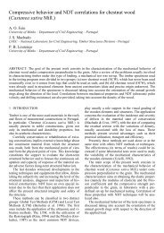
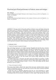
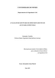
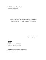
![Weibull [Compatibility Mode]](https://img.yumpu.com/48296360/1/190x134/weibull-compatibility-mode.jpg?quality=85)