Alex Haptemariam - Maryland Department of Natural Resources Data
Alex Haptemariam - Maryland Department of Natural Resources Data
Alex Haptemariam - Maryland Department of Natural Resources Data

Create successful ePaper yourself
Turn your PDF publications into a flip-book with our unique Google optimized e-Paper software.
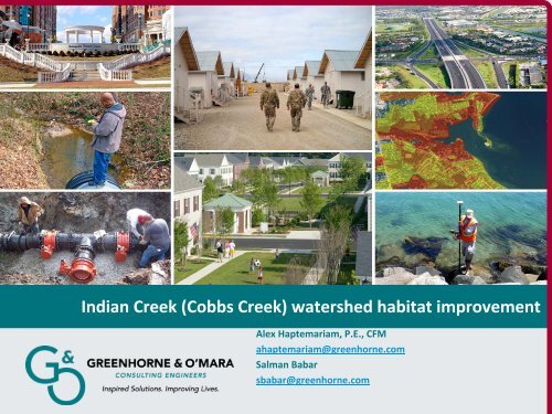
Indian Creek (Cobbs Creek) watershed habitat improvement<br />
<strong>Alex</strong> <strong>Haptemariam</strong>, P.E., CFM<br />
ahaptemariam@greenhorne.com<br />
Salman Babar<br />
sbabar@greenhorne.com
Project Location
Watershed Characterization<br />
• Watershed is located in Southern Montgomery County &<br />
Western section <strong>of</strong> the City <strong>of</strong> Philadelphia along the eastern<br />
edge <strong>of</strong> Piedmont Physiographic province and is characterized<br />
by gently rolling to hilly topography.<br />
• The total watershed area is 3.4 sq. miles.<br />
• The upper portion <strong>of</strong> the watershed is characterized by hilly to<br />
steep topography with slopes ranging from 3% to 15% .<br />
• Channel gradient varies from 1.4% to 3%.
Background:<br />
• 20% <strong>of</strong> Cobbs Creek watershed is serviced by combined<br />
sewers.<br />
• City <strong>of</strong> Philadelphia has 38 regulator structures within<br />
the watershed.<br />
• CSO discharges are the major source <strong>of</strong> fecal coliform<br />
in Cobbs Creek Watershed.
Objective:<br />
• Reduce and eliminate point source discharge<br />
• Improve the Creeks water quality and reducing local<br />
overflow<br />
• Stream bed and bank stabilization<br />
• Wetland and habitat creation<br />
• Elimination <strong>of</strong> debris accumulation
Problems & Issues<br />
• Current conditions along East & West branch are<br />
characterized as very unstable.<br />
• Sediment transport issues at downstream<br />
• Stream bank erosion, lateral migration, channel<br />
blockages and stream bed aggradation & degradation<br />
are common throughout.<br />
• CSO intake headwall clogging issues<br />
• Accumulated sediment at CSO intake headwall<br />
• Severe erosion at Haverford Avenue bridge
Debris accumulation
Accumulated sediment
Damages
Urban Stream Restoration Challenges:<br />
• Typically requires much greater degree <strong>of</strong> hydrologic &<br />
hydraulic analysis<br />
• Sediment transport studies<br />
• Bankfull indicator challenges<br />
• Reduce base flow<br />
• Increased flood flow<br />
• Reduced Time <strong>of</strong> Concentration (Tc)
CSO Challenges:<br />
Infrastructure:<br />
•a) Aged Pipes<br />
•b) Aged Manholes<br />
•c) Existing infrastructure information<br />
Maintenance:<br />
•4 chamber manhole<br />
•Fire hydrant<br />
•Manhole at upstream end <strong>of</strong> 6’x6’ box culvert<br />
•Access manholes
Methods <strong>of</strong> <strong>Data</strong> Collection<br />
• Existing data was collected, compiled and reviewed.<br />
• Modeling and field studies were conducted to evaluate the<br />
current conditions along East & West branch.<br />
• The data collected was utilized to determine structure type, size<br />
and location.<br />
• Restoration and management recommendations, design<br />
concepts as well as preliminary cost estimates for restoration<br />
and management strategies were developed.<br />
• The study included identification <strong>of</strong> significant plants and<br />
plantation <strong>of</strong> trees, HTRW studies and CSO inspection report.
Achievements:<br />
Volume reduction:<br />
•An average annual volume reduction from 2.9 to 1.2 million gallons (58%<br />
reduction) from regulator C_05<br />
CSO frequency reduction:<br />
•An average annual reduction in CSO frequency reduction from 17 to 13<br />
overflows per year from regulator C_05<br />
•Pollutants removal<br />
Cost effective & Environment friendly:<br />
•CSO reductions were achieved without the construction <strong>of</strong> new storage facilities<br />
Replaced aged infrastructure:<br />
•New manhole C‐1 and wellhole W‐1
Hydrology<br />
24-hour Peak Discharge<br />
Storm Event East Branch West Branch<br />
Design Flow 802 CFS 297 CFS<br />
1.5-YR 1080 CFS 350 CFS<br />
2-YR 1350 CFS 450 CFS<br />
10-YR 2430 CFS 850 CFS<br />
50-YR 3390 CFS 1300 CFS<br />
100-YR 3610 CFS 1500 CFS
Hydrology (cont..)<br />
Bankfull discharge estimates:<br />
Three methods were used to estimate the bankfull discharge<br />
1.Regional regressions developed for use in urban watershed.<br />
2.USGS regional regressions<br />
3.Hydrologic model output provided by Philadelphia Water<br />
<strong>Department</strong> (PWD)<br />
4.Manning's equation and field data
Hydrology (cont..)<br />
Bankfull Discharge Estimates (West branch)<br />
Method 1-YR (cfs) Bankfull (cfs) 2-YR (cfs)<br />
Regional Regression ND 296 ND<br />
USGS ND ND 416<br />
PWD 98 ND 450<br />
Manning's Equation ND 297.3 ND<br />
Bankfull Discharge Estimates (East branch)<br />
Method 1-YR (cfs) Bankfull (cfs) 2-YR (cfs)<br />
Regional Regression ND 294 ND<br />
USGS ND ND 408<br />
PWD 365 ND 1350<br />
Manning's Equation ND 296 ND
Bankfull Channel Geometry Comparision
Classification Summary Table
Hydraulic Analysis<br />
• Analyze existing water surface elevations, channel<br />
velocities and other pertinent hydraulic parameters<br />
associated with the channel.<br />
• US Army Corps <strong>of</strong> Engineers Hec‐RAS computer modeling<br />
program was used to perform hydraulic analysis.
Functions <strong>of</strong> In‐stream Structures<br />
• Maintain stable W/D ratio<br />
• Maintain necessary shear stress to move large particles<br />
• Decrease near bank velocity, shear stress or stream power<br />
• Ensure stability <strong>of</strong> structure during high flows (floods)<br />
• Maintain fish passage at all flows<br />
• Improves fish habitat and fish spawning<br />
• Visibly compatible with natural channels<br />
• Less costly than traditional structures
Considerations for In‐stream structures<br />
• Rock size is based on bankfull shear stress and stream size<br />
• Footers are used in absence <strong>of</strong> bedrock<br />
• Location <strong>of</strong> these structures is finalized after proper design<br />
<strong>of</strong> dimension, pattern and pr<strong>of</strong>ile for the restored channel
Types <strong>of</strong> In‐stream structures used<br />
• Cross vanes<br />
• Rock vanes<br />
• J‐hook vanes:<br />
• Imbricated riprap wall<br />
• Step pools
Instream Structure Details
Instream Structure Details
Under cutting in West branch
Eroding banks
Stormdrain relocation<br />
• To ensure natural design<br />
• Taking out hardened infrastructure such as RCP and<br />
headwall<br />
• 18” RCP exposed along West branch will be reconstructed<br />
and relocated.
Bankfull benches
Bankfull benches
East branch
Routing between sewer interceptor & regulator:
Representation <strong>of</strong> drainage connection to<br />
Interceptor
CSO Design<br />
• CSO design includes a weir wall with 24” orifice inside<br />
concrete vault structure.<br />
• The 24” orifice is used to divert the flow from the vault into<br />
the existing sewer interceptor.<br />
• The 24” orifice size was selected to reduce the likelihood <strong>of</strong><br />
clogging.<br />
• The existing 700LF <strong>of</strong> underground reinforced concrete box<br />
(RCB) serves as storage during large storm events.<br />
• The downstream portion <strong>of</strong> the existing reinforced<br />
concrete box (RCB) will be removed.
Connection between regulator & overflow
Connection between Interceptor and regulator
CSO regulating chamber V‐1 details
CSO regulating chamber C‐1 details
Connection details
Thank You!<br />
Questions!!