Download - Trade Garage Equipment
Download - Trade Garage Equipment
Download - Trade Garage Equipment

You also want an ePaper? Increase the reach of your titles
YUMPU automatically turns print PDFs into web optimized ePapers that Google loves.
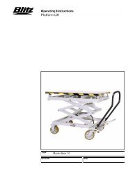
SCISSOR LIFT WITH RAMPS<br />
OPERATING INSTRUCTIONS<br />
MIRACH<br />
TRUCK
SCISSOR LIFT<br />
EC DECLARATION OF CONFORMITY<br />
The Company<br />
MARTE s.r.l.<br />
Via Custoza 15<br />
66013-CHIETI SCALO (ITALIA)<br />
Tel. 0871/574008-Fax 0871/574092<br />
DECLARES ON ONE’S OWN RESPONSIBILITY THAT THE EQUIPMENT SPECIFIED BELOW:<br />
TYPE OF EQUIPMENTS:<br />
SCISSOR LIFT WITH RAMPS<br />
MODEL: MIRACH 100 ; 200 ; 300 . 400 <br />
PART NUMBER: ..............................................<br />
TO WHICH THIS DECLARATION IS RELATED, CONFORMS WITH THE FOLLOWING EUROPEAN<br />
DIRECTIVES: 98/37 CE - 73/23 CEE - 93/44 CEE - 93/68 CEE - 89/336.<br />
IT ALSO DECLARES THAT THE FOLLOWING EUROPEAN RULES HAVE BEEN RESPECTED :<br />
EN 292.1- EN 292.2- EN 294-EN 349- EN 1050- EN 60204-1. - ETS 300683 EN 55022B.<br />
Name and address of the approval body: TÜV PRODUCT SERVICE GMBH - Zertifierstelle<br />
Ridlerstrasse 31<br />
D-80339 Munchen<br />
Certificate number: M6 98 12 29366 005<br />
Notifiziert bei der EG Kommission unter Nr. 0123<br />
---------------------------------------------------------------------------- -------------------------------------------------------------------------<br />
(Place and date)<br />
(MANAGING DIRECTOR)<br />
YEAR OF MANUFACTURE<br />
VOLTAGE 220/380 Vac 220 Vac 240 Vac 110 Vac<br />
Hz 50 Hz 60 Hz<br />
AUTHORIZED SERVICE CENTER<br />
2
CONTENTS<br />
FIRST PART<br />
Chapter 1-Introduction-packing-transport page 3<br />
Chapter 2-Machine description page 4<br />
Chapter 3-Safety page 7<br />
Chapter 4-Installation page 8<br />
Chapter 5-Operation page 24<br />
Chapter 6-Maintenance page 24<br />
Chapter 7-Troubleshooting page 25<br />
Chapter 8-Accessories page 25<br />
Chapter 9-Spare parts page 25<br />
SECOND PART (For installer’s use)<br />
Inspection check list<br />
SYMBOLS<br />
HAZARD-DANGER<br />
PROHIBITED<br />
WARNING<br />
Follow the instructions given by the messages preceded by a safety alert symbol<br />
CHAPTER 1- INTRODUCTION - PACKAGING - TRANSPORT<br />
INTRODUCTION<br />
This manual was written for shop technicians (Truck lift operators) and maintenance technicians. Before operating these vehicle lifts,<br />
please read these instructions completely. This manual gives helpful information about:<br />
• Safety of personnel;<br />
• Safety of the vehicle lift;<br />
• Safety of lifted vehicle.<br />
This manual is considered to be a permanent part of the lift and must be kept in an easily accessible place so that the operator can find<br />
it and refer to it. Careful reading of chapter 3 on safety is recommended.<br />
All versions of “MIRACH TRUCK” have been designed and built as required by:<br />
EUROPEAN RECOMMENDATIONS: EEC 89/392, EEC 93/68;<br />
EUROPEAN RULES: EN 291/1992, EN 292/1992;<br />
ITALIAN RULES: UNI 9584 and UNI EN 60204 CEI 64/8 concerning the electrical system.<br />
Only skilled and previously authorized technicians should be allowed to carry out transport, assembling, setting, maintenance, overhaul,<br />
moving, dismantling operations, etc. concerning the lift. The manufacturer is not responsible for possible damage to people, vehicles<br />
and objects in the case that said operations are carried out by unauthorized personnel or the lift improperly used.<br />
Always start the hydraulic and electric system before the pneumatic connection from the lift to the control box is carried out.<br />
Read these instructions completely before operating the lift.<br />
The lift must be used for vehicles up to the specified capacity. Any improper use of this lift is strictly forbidden.<br />
Disconnect the lift from the main electric supply before any extraordinary maintenance operation.<br />
Lift installation must be carried out as specified by these instructions.<br />
The manufacturer is not liable for possible damage resulting from failure to follow the instructions supplied with this truck-lift.<br />
PACKAGING<br />
MIRACH “100”<br />
A- Bases and platforms (P1-P2) placed on top of each other<br />
B- Lifting ramps (surface mounted version) or 4 small ramps.<br />
C- Control box.<br />
D- Cardboard box containing with electric and hydraulic connections.<br />
MIRACH “200-300”<br />
A- Base and platform P1 closed.<br />
A¹ Base and platform P2 closed.<br />
B- Lifting ramps (surface mounted version) or 4 small ramps.<br />
C- Control box.<br />
D- Cardboard box containing with electric and hydraulic connections.<br />
MIRACH “400”<br />
A- First part base-platform P1 closed.<br />
A¹- Second part base-platform P1 closed.<br />
A²- First part base-platform P2 closed.<br />
A³- Second part base-platform P2 closed.<br />
B- Lifting ramps (surface mounted version) or 4 small ramps.<br />
C- Control box.<br />
D- Cardboard box containing with electric and hydraulic connections.<br />
TRANSPORT<br />
Bundles can be lifted or moved by lift trucks, cranes or bridge cranes. In case of slinging, a second person must always take care of the<br />
load to avoid dangerous oscillations. At the arrival of goods, check for possble damage due to transport operations. Also verify that all<br />
items specified in the delivery notes are included. In case of damage or possible defects in transit the person in charge or the carrier<br />
must be immediately informed. Furthermore, during loading and unloading operations goods must be handled as shown in the picture.<br />
3
PACKING REMOVAL<br />
Wood and “bubble wrap” can be recycled. Please comly with local<br />
recycling laws<br />
PACKAGING<br />
MODELS A B C KG.<br />
Lift<br />
6000 460 870 1700<br />
Control box 970 355 450 80<br />
Ramps 3000 400 870 200<br />
Cardboard box 400 300 200 10<br />
TOTAL<br />
3690<br />
M 100<br />
Lift<br />
Control box<br />
Ramps<br />
Cardboard box<br />
7700<br />
600*<br />
3000<br />
400<br />
460<br />
1100*<br />
400<br />
300<br />
870<br />
800*<br />
870<br />
200<br />
2500<br />
150<br />
200<br />
10<br />
TOTAL<br />
5360<br />
M 200<br />
Lift<br />
Control box<br />
Ramps<br />
Cardboard box<br />
10550<br />
600*<br />
3000<br />
400<br />
460<br />
1100*<br />
400<br />
300<br />
870<br />
800*<br />
870<br />
200<br />
3500<br />
160<br />
200<br />
10<br />
TOTAL<br />
7370<br />
M 300<br />
Lift<br />
Control box<br />
Ramps<br />
Cardboard box<br />
7050<br />
600*<br />
3000<br />
400<br />
460<br />
1100*<br />
400<br />
300<br />
870<br />
800*<br />
870<br />
200<br />
2500<br />
200<br />
200<br />
15<br />
M400<br />
TOTAL<br />
*The dimensions are shown with the power unit packaged in a vertical position.<br />
CHAPTER 2 -LIFT DESCRIPTION<br />
“MIRACH TRUCK” models are scissor and fixed (that is anchored to the ground) truck lift and can be delivered in both platform or<br />
recessed version. They have been designed and built for medium and large truck lifting operations. Our truck lifts are equipped as<br />
follows:<br />
A-BASE (Fixed structure); B-PLATFORM AND BOOMS (Lifting and travelling structure); C-CONTROL BOX.<br />
M-Serial number A-Warning label<br />
10415<br />
M-Serial number<br />
4
• FIXED STRUCTURE UNIT; It is the truck lift base, made of profiled steel sheet with clamping holes.<br />
• LIFTING AND TRAVELLING STRUCTURE UNIT; It is composed of box-type steel sheet booms. The load-carryng platform is made<br />
of longitudinal steel tubes linked to each other by vertical rods anchored to the booms by steel pins at the fixed points, and by rollers<br />
at the movable ones. Liftting system links are equipped with self-lubricating bushings where servicing is not required.<br />
• CONTROL BOX; The unit with a metallic box that contains oil tank, pump, motor, hand pump and electrovalve sets. There are also<br />
power, pneumatic and hydraulic supply connections. Low-voltage controls (24 V) are placed on the power unit.<br />
1. Mains witch.<br />
2. Lifting push button.<br />
3. Lowering push button.<br />
4. Feeding pilot lamp.<br />
5. Self levelling pilot lamp.<br />
6. Lifting limit switch.<br />
7. Light selector (where provided).<br />
8. Mechanical safety device.<br />
M “100” M “200-300-400”<br />
1-Main switch: When it’s in “0” position lift is not powered. The switch can be padlocked to prevent the use of the lift during the<br />
maintenance. “1” position: lift is powered.<br />
2- Lifting push button: When pressed, motor and lifting mechanism are operated.<br />
3- Lowering push button: When pressed, motor and lowering mechanism are operated.<br />
4- Feeding pilot lamp: Indicates that the control board is powered.<br />
5- Self levelling pilot lamp: Indicates that the self levelling is operating.<br />
6- Lifting limit switch cut out: Located inside the control box. This push button is used for making lift bleeding during installation and<br />
levelling.<br />
7- Light selector: (where provided) this selector activates lighting installation.<br />
8- Mechanical safety device: When pressed mechanical safety is engaged.<br />
Warning! only truck lift installation and maintenance personnel should be allowed to handle this control. Handling this<br />
button is strictly forbidden to unauthorized people.<br />
All “MIRACH TRUCK” versions have an adjustable height. So that they can easily be used and safely as needed. Our range of scissor<br />
truck lifts can meet any demand coming from car repairmen, tire dealers, body repairmen and in the special versions equipped for<br />
external use and industrial washing applications ones.<br />
LIFT MODELS: (AS SHOWN BELOW)<br />
MIRACH 100<br />
CAPACITY 10.000 KG.<br />
MIRACH 200<br />
CAPACITY 20.000 KG.<br />
MIRACH 300<br />
CAPACITY 30.000 KG<br />
MIRACH 400<br />
CAPACITY 40.000 KG.<br />
WARNING: “Mirach truck lift” has been designed and built to lift and place trucks at heights in closed areas. Any other use is strictly<br />
forbidden, and particularly, the following operations cannot be performed:<br />
PAINTING; AS A CRANE; LIFTING OF PEOPLE OR SCAFFOLDING; AS A HYDRAULIC PRESS;CAR JACK OR WHEEL<br />
REPLACEMENT.<br />
5
TECHNICAL SPECIFICATIONS-CHARACTERISTICS:<br />
• Low-voltage controls (24V)<br />
• Control box with electro-mechanical card.<br />
• Hydraulic- volumetric synchronism of platform.<br />
• Foot guard with automatic lowering cut out switch<br />
• Safety valve in case of hydraulic failure overloading<br />
• Mechanical safety ratchet on lift<br />
• Device for synchronization of platform.<br />
TECHNICAL DATA<br />
MIRACH 100 200 300 400<br />
OPERATION Elec.hydr. Elec.hydr. Elec.hydr. Elec.hydr.<br />
CAPACITY 10.000 KG. 20.000 KG. 30.000 KG. 40.000 KG.<br />
WEIGHT<br />
3.260 KG. in floor<br />
3.460 KG. on floor<br />
5.000 KG. in floor<br />
5.250 KG. on floor<br />
7.000 KG. in floor<br />
7.250 KG. on floor<br />
10.000 KG. in floor<br />
10.250 KG. on floor<br />
LIFTING TIME 90 sec. 90 sec. 90 sec. 90 sec.<br />
LOWERING TIME<br />
30 sec. 30 sec. 30 sec. 30 sec.<br />
(WITH LOAD)<br />
MAX LIFTING HEIGHT 1850 mm. 1850 mm. 1850 mm. 1850 mm.<br />
MOTOR<br />
3 phase 4KW<br />
(6 HP)<br />
3 phase 7,5 KW<br />
(10 HP)<br />
3 phase 11 KW<br />
(15 HP)<br />
2x 3 phase 7,5 KW<br />
(2x10 HP)<br />
PNEUMATIC FEED from 4 to 8 bar from 4 to 8 bar from 4 to 8 bar from 4 to 8 bar<br />
NOISY LEVEL 76 dB 76 dB 76 dB 76 dB<br />
WORKING TEMP. -10°+50° -10°+50° -10°+50° -10°+50°<br />
WORKING<br />
120 Bar 120 Bar 120 Bar 120 Bar<br />
MAX PRESSure<br />
THE DIRECTION OF THE MOTOR IS COUNTERCLOCKWISE, AS SHOWN IN THE TABLE PLACED ON THE MOTOR.<br />
OVERALL DIMENSIONS<br />
MIRACH 100<br />
MIRACH 200<br />
MIRACH 300<br />
MIRACH 400<br />
6
CHAPTER 3 -SAFETY<br />
GENERAL PRECAUTIONS<br />
Read this chapter carefully and completely since important information for the safety of the operator in case of improper use of the lift<br />
included. The operator and the maintenance personnel are required to observe the accident prevention legislation in force in the country<br />
of installation of the lift.<br />
1-During lifting or lowering operations, the truck lifts must be operated only from the operator area as shown in the picture<br />
2-Stopping or passing within the danger area when the lift is working or already lifted is strictly forbidden. Only the operator is<br />
allowed to stay under the lift.<br />
3-The operator must make sure the hazard area is empty when lifting or lowering the lift.<br />
4-Never use the machine without protection or when safety devices are off-line.<br />
5-Switch off the engine and engage the parking brake after placing the vehicle on the truck lift; Furthermore, disengage the<br />
shift lever and move it to the “neutral” position.<br />
6-To prevent the vehicle from falling make sure it is properly placed on the lift.<br />
7-Getting on the vehicle and-or starting the engine when the truck lift is lifted is strictly forbidden.<br />
8-Never leave objects and-or obstructions under the vehicle or scattered on it during the lowering phase.<br />
9-Keep the area under/next to the lift clear and remove possible oil spots to avoid the risk of slipping.<br />
10-Never use water-steam-varnish-solvent jets in the truck lift area, and particularly, next to the control box.<br />
11-Proper lighting is extremely important. Make sure all areas next to the truck lift are well and uniformly lit according to that<br />
specified by the applicable laws of the place of installation.<br />
12-Climbing on the platform when lifting the vehicle or when the same has been already lifted is strictly forbidden.<br />
13-Any use of the truck lift other than what herein specified can cause serious accidents to the operator as well as to the<br />
people in close proximity.<br />
14-The tampering of safety devices is strictly forbidden.<br />
15-Never exceed the maximum carryng capacity, Make sure the vehicles to be lifted are without loads.<br />
In case of irregularities or problems with the lift, stop the truck lift and block the on/off selector by using a padlock. Only<br />
skilled technicians should be allowed to restart the truck lift. Be sure the power supply is off before repairing and servicing the<br />
truck lift. The operator, the lift or the vehicles lifted can be seriously damaged if these instruction are not follwed.<br />
SAFETY DEVICES<br />
Foot guard for platform lowqering. Truck lift lowering can be stopped immediately by pressing one of the movable strips located on<br />
side of each platform.<br />
Safety valve for automatic lowering. Normally open two-way safety valves. They are able to automatically lock a single or doubleacting<br />
cylinder in case of a sudden increase in lowering speed. The valves are located inside the cylinders and prevent the load from<br />
failing in case of sudden pipe bursting or cutting.<br />
Dead man control The truck lift is equipped with a dead-man control. Lowering and lifting operations are stopped immediately by<br />
releasing push button controls.<br />
Mechanical safety ratchet. A metallic device, pneumatically piloted.<br />
CHAPTER 4- INSTALLATION<br />
UNPACK THE GOODS AND CHECK FOR POSSIBLE DAMAGE BEFORE INSTALLING THE TRUCK LIFT.<br />
ONLY SKILLED TECHNICIANS, APPOINTED BY THE MANUFACTURER, OR BY AUTHORIZED DEALERS SHOULD BE<br />
ALLOWED TO INSTALL THE CAR LIFT. SERIOUS DAMAGE TO PEOPLE OR EQUIPMENT CAN BE CAUSED IF THIS RULE IS NOT<br />
FOLLOWED.<br />
The truck lift must be installed according to the specified safe distance from walls, columns, other equipments etc. The room must be a<br />
minimum 5000 mm. in height. The minimum distance from walls must be 1500 mm. take into consideration the necessary space to work<br />
comfortably. Further space for the control site and for possible runways in case of emergency is also necessary. The lift can be placed<br />
on any floor, as long as is perfectly level and sufficiently resistant. (250 x cm²).<br />
7
INSTALLATION PROCEDURE<br />
1-Lift location 2-Power supply and pneumatic feed availability 3-Electric connections<br />
4-Hydraulic connections 5-Electric network connection 6-Lift installation<br />
7-Initial running<br />
1) LOCATION OF THE LIFT<br />
Because of the considerable weight and dimensions of some of our lifts, it may be necessary to use an overhead or a crane with a<br />
suitable capacity to place them as indicated below. After having determined the location of the lift, it may be necessary to shim under the<br />
lift base to make the lift level.<br />
2) POWER SUPPLY AND PNEUMATIC FEED AVAILABILITY .<br />
The room must be previously prepared for the power supply and pneumatic feed of the lift. Make sure that supplies are not far from the<br />
power unit.<br />
3)ELECTRIC CONNECTIONS<br />
Connect the cables marked with a self adhesive number from the truck lift bases to the previously numbered cables of the control box.<br />
MIRACH 100- WIRING CONNECTIONS<br />
2 06-6133 P2 platform self levelling 3 06-6133 P1 Platform self levelling<br />
4 06-6130 Foot guard 5 06-6034 Platform lifting limit switch<br />
6 06-6503 Junction box<br />
8
MIRACH 200-WIRING CONNECTIONS<br />
1 06-6610 Platform mechanical safety device 2 06-6133 P2 platform self levelling<br />
3 06-6133 P1 platform self levelling 4 06-6130 Foot guard<br />
5 06-6034 Platform lifting limit switch 6 06-6503 Junction box<br />
MIRACH 300-WIRING CONNECTIONS<br />
1 06-6610 Platform mechanical safety device 2 06-6133 P2 platform self levelling<br />
3 06-6133 P1 platform self levelling 4 06-6130 Foot guard<br />
5 06-6034 Platform lifting limit switch 6 06-6503 Junction box<br />
9
MIRACH 400 -WIRING CONNECTIONS<br />
1 06-6610 Platform mechanical safety device 2 06-6133 P2 platform self levelling<br />
3 06-6133 P1 platform self levelling 4 06-6130 Foot guard<br />
5 06-6034 Platform lifting limit switch 6 06-6503 Junction box<br />
WIRING DIAGRAM<br />
MIRACH 100<br />
10
MIRACH 200-300<br />
MIRACH 400<br />
C ELECTRO-VALVE CONTACTOR PA SAFETY BUTTON<br />
C1-C2 ELECTROLYTIC CAPACITOR POT TRIMMER<br />
CM (CM1-CM2) MOTOR CONTACTOR PES LIMIT SWITCH SAFETY CUT OUT<br />
DL0/DL5 LED PEF LIMIT SWITCH CUT OUT<br />
D0/D2 DIODE RD LOWERING RELAY<br />
ES LEVELLING CONTROL ELECTROVALVE RST LINE INPUT<br />
EL LEVELLING ELECTROVALVE RS SAFETY RELAY<br />
EA AIR ELECTRO VALVE R1/R8 RESISTOR<br />
EO LOWERING OIL ELECTRO VALVE RL LIGHTS RELAY<br />
F1/F6 FUSE TR-TR1 TRANSFORMER 50VA-300VA<br />
M MOTOR FCS SAFETY LIMIT SWITCH<br />
N1/N2 SINGLE PHASE BRIDGE L2 LEVELLING SIGNAL LAMP<br />
PS LIFTING BUTTON T TIMER<br />
PD LOWERING BUTTON FM MECHANICAL SAFETY LIMIT SWITCH<br />
11
4) HYDRAULIC CONNECTIONS<br />
“MIRACH 100” HYDRAULIC CONNECTION<br />
A<br />
DELIVERY<br />
B<br />
DISCHARGE<br />
C<br />
LEVELLING AND DELIVERY P2<br />
D<br />
LEVELLING AND DELIVERY P1<br />
AA<br />
CONNECTION DELIVERY P1<br />
CH<br />
CONNECTION P1-P2<br />
DG<br />
CONNECTION P1-P2<br />
BB<br />
DISCHARGE CONNECTIONS P2<br />
1/8 CONNECTIONS ON LIFT<br />
E-(A)<br />
CONNECTIONS IN CONTROL BOX<br />
12
HYDRAULIC CONNECTION “MIRACH 200”<br />
13
HYDRAULIC CONNECTION “MIRACH 300”<br />
14
HYDRAULIC CONNECTION “MIRACH 400”<br />
15
HYDRAULIC CONNECTIONS “MIRACH 200-300”<br />
Hydraulic connection to the control box<br />
Mirach 200 Mirach 300<br />
HYDRAULIC CONNECTIONS “MIRACH 400”<br />
Hydraulic connection to the control box<br />
16
HYDRAULIC SCHEMATIC “MIRACH 100”<br />
1 PARACHUTE VALVE 9 MOTOR<br />
2 P1 PISTON 10 PUMP<br />
3 P2 PISTON 11 SUCTION FILTER<br />
4 COMPENSATION VALVE 12 COCK<br />
5 THROTTLING ELECTROVALVE 13 DISCHARGE<br />
6 LOWERING ELECTROVALVE 14 OIL TANK<br />
7 FULL FORCE VALVE 15 OIL<br />
8 LOWERING CONTROL VALVE<br />
17
HYDRAULIC SCHEMATIC “MIRACH 200”<br />
1 PARACHUTE VALVE 9 MOTOR<br />
2 P1 PISTON 10 PUMP<br />
3 P2 PISTON 11 SUCTION FILTER<br />
4 COMPENSATION VALVE 12 COCK<br />
5 THROTTLING ELECTROVALVE 13 DISCHARGE<br />
6 LOWERING ELECTROVALVE 14 OIL TANK<br />
7 FULL FORCE VALVE 15 OIL<br />
18
HYDRAULIC SCHEMATIC “MIRACH 300”<br />
1 PARACHUTE VALVE 9 MOTOR<br />
2 P1 PISTON 10 PUMP<br />
3 P2 PISTON 11 SUCTION FILTER<br />
4 COMPENSATION VALVE 12 COCK<br />
5 THROTTLING ELECTROVALVE 13 DISCHARGE<br />
6 LOWERING ELECTROVALVE 14 OIL TANK<br />
7 FULL FORCE VALVE 15 OIL<br />
19
HYDRAULIC SCHEMATIC “MIRACH 400”<br />
1 PARACHUTE VALVE 9 MOTOR<br />
2 P1 PISTON 10 PUMP<br />
3 P2 PISTON 11 SUCTION FILTER<br />
4 COMPENSATION VALVE 12 COCK<br />
5 THROTTLING ELECTROVALVE 13 DISCHARGE<br />
6 LOWERING ELECTROVALVE 14 OIL TANK<br />
7 FULL FORCE VALVE 15 OIL<br />
20
PNEUMATIC SCHEMATIC<br />
1 Main supply 2 control box<br />
3 Air electrovalve 4 “rilsan” white air tubing<br />
5 tee 6 Pneumatic jack for mechanical safety release<br />
7 P1 8 P2<br />
9 Air filter and lubricator<br />
21
5) ELECTRICAL SYSTEM CONNECTION<br />
Warning ! Only skilled personnel should be allowed to perform the operation shown below.<br />
Connect as follow:<br />
• Open the control box front cover and using a proper terminal box, connect the electric cable to the general switch cable (be sure that<br />
the cable passes trought the proper space located behind the control box). This truck lift is designed to operate on 380V, in case of<br />
different voltage, change both connections to the motor and the transformer. Before connecting the electric system, make sure that<br />
the power supply plant to the lift is equipped with protection devices required by current standards in the country where the lift is<br />
installed.<br />
WARNING<br />
Before gaining access to the control box, for power connection or for repair of electric equipment, make sure that the main<br />
power supply is disconnected, to avoid the possibility of electrocution.<br />
COMMERCIAL PARTS “WIRING PLANT”<br />
Position n. Denomination Manufacturer Type Max<br />
application<br />
1-2 Footguard/mechanical safety devices<br />
OMRON<br />
D4 MC 2000 24 V<br />
microswitches<br />
3 Self-levelling microswitch. OMRON MS TZ 7310 24V<br />
4 Lifting limit microswitch. PIZZATO FR 502 24V<br />
electric wire<br />
VARIOUS<br />
Junction box<br />
GEWISS<br />
IG General switch SPRECHER SCHUH LE3-32-32A / LE2-16-16A<br />
PA/PD/PEF Button SPRECHER SCHUH RT010<br />
L1 Pilot lamp SPRECHER SCHUH SR 601<br />
Contact NO/NC SPRECHER SCHUH V50/P-V40/P<br />
Tripolar fuse carrier WEBER 32A-660V (25A-380V M80)<br />
Bipolar fuse carrie WEBER 32A-160V<br />
F1÷F6 Fuse WEBER VARIOUS<br />
16 Contactor “200-300-400”<br />
Contactor “100”<br />
CGE<br />
SPRECHER SCHUH<br />
35A<br />
16A<br />
TR Transformer LSP 50VA-300VA<br />
18-19 Basis for relay FINDER 24V DC - 24VAC<br />
20 Electric card MARTE<br />
PNEUMATIC PLANT (4/8 BAR)<br />
Position n. Denomination Manufacturer Type Max<br />
application<br />
1 Air electrovalve ACL/MM 24V~ 50/60 HZ 8VA 10 Bar<br />
2 Pneumatic connections Various Various 16 Bar<br />
3 Pneumatic pipe Rilsan Ø 4 x 6 30 Bar<br />
4 Air piston Marte 15 bar<br />
HYDRAULIC PLAN<br />
Position n. Denomination Manufacturer Type Max<br />
application<br />
14 Oil tank MARTE<br />
11 Suction filter FBN SF46B 12 GO<br />
10 Pump “200-300-400”<br />
Pump “100”<br />
HYDROIRMA<br />
“<br />
025-1659-76 15 Lt.<br />
010-1559-32 8 lT<br />
250 Bar<br />
250 Bar<br />
9 Motor BAME 220/380-3PM-50HZ 2830 RPM<br />
4KW 6 HP - 7,5 KW 10 HP<br />
7 Max pressure valve COMATROL 35/220 Bar<br />
6-4-5 Electrovalves COMATROL 24V RAC 26 W - 24V AC 20 W 250 Bar<br />
12 Manual cock TECLINE<br />
1 Parachute valve MONTI VP 38 15/18 lt.<br />
2 P1 piston MONTI Ø 150 300 Bar<br />
3 P2 piston MONTI Ø 140 300 Bar<br />
R1-R2 Hydraulic pipe ALFA GOMMA VARIOUS 210 -400 Bar<br />
Crimp fitting LARGA VARIOUS 400 Bar<br />
8 (M 100) Lowering control valve “100” HYDROIRMA VRC 10/11 230 Bar<br />
22
6) LIFT INSTALLATION<br />
After making electric and hydraulic connections, make sure they are properly connected. Now fix the lift to the floor, using the bases as<br />
templates, drill a hole into the floor ca 18 mm. Ø bit must be used up to a depth of about 150 mm., clean the holes, place the proper<br />
inserts with light hammer blows and finally tighten the bolts. In case of an inground lift check if it is perfecly centred. Platform lifting limit<br />
switch is already adjusted during assembly stage to the maximum lifting height 1850 mm., however the operator can adjust it according<br />
to own requirements not exceeding the maximum height indicated.<br />
7) INITIAL RUNNING<br />
WARNING! ONLY SKILLED AND AUTHORIZED PERSONNEL SHOULD BE ALLOWED TO PERFORM THESE OPERATIONS.<br />
CAREFULLY FOLLOW ALL INSTRUCTIONS SHOWN BELOW TO PREVENT POSSIBLE DAMAGE TO THE TRUCK LIFT OR<br />
RISK OF INJURY TO PEOPLE.<br />
BE SURE THAT THE OPERATING AREA IS CLEARED OF PEOPLE.<br />
After positioning the truck lift as specified on the previous pages, and performing electric and hydraulic connections (do not perform<br />
pneumatic connection yet) the truck lift can be operated by the procedures shown below: Open the front door of the control box and<br />
unscrew the oil tank cap, and using a funnel pour “ESSO NUTO H 32” hydraulic oil in the following manner:<br />
M 100 M200 M300 M400<br />
30 Lt. 60 Lt. 80 Lt 100 Lt.<br />
Move the general switch to “1” position. Be sure the motor for the proper direction of rotation (failing this, exchange the phase on the<br />
feeder line). Press the “lifting” push button and keep it pressed until the “P1” platform comes to a stop. Add. oil in the tank in this way:<br />
M 100 M200 M300 M400<br />
15 Lt. 20 Lt. 40 Lt. 70 Lt.<br />
Symultaneously press the “lifting” and “limit switch cut out” push buttons, and hold them pressed until the “P2” platform starts moving;<br />
keeping on pushing until the pump sucks in air. Add. more oil in the tank as indicated below:<br />
M 100 M200 M300 M400<br />
5 Lt. 20 Lt. 30 Lt. 30 Lt.<br />
.Again simultaneously press the two buttons specified above (lifting and limit switch cut out) until the P2 platform reaches its maximum<br />
height. Keep the buttons pressed for about 20 sec. (now, the pneumatic connection can be performed). To lower the two platforms,<br />
press the “lowering” button. Repeat lifting/lowering operations three or four times.<br />
CHAPTER 5 - OPERATION<br />
-Be sure the platform reaches its minimum height before getting on-off the truck lift.<br />
-Drive the truck on the lift, be sure the truck is centred and both rear and front wheels are properly positioned.<br />
-To operate on-off general switch in “1” position.<br />
-Press the “lifting” push button, and hold pressed until the required height is reached.<br />
-To lower press the “lowering” push button, when this button is pressed, a short lifting movement occurs so that the mechanical safety<br />
device can be disengaged. When the push button is released, the truck lift cames to a stop.<br />
During the first hours of operation, cracking noises could occur. These initial noises are only due to the natural settlement<br />
of mechanical parts and will disappear .<br />
CHECKS<br />
Perform the following checks when operating the truck lift.<br />
-Be sure that mechanical safety devices are properly inserted in their seats.<br />
-Check safety devices (foot guards) for proper operation.<br />
-Carefully check the truck lift and its load during lifting-lowering operations.<br />
CHAPTER 6 - MAINTENANCE<br />
WARNING! Only skilled and previously authorized personnel should be allowed to service the truck lift. When servicing the truck lift,<br />
all safety precautions must be followed to avoid accidental starting of the machine. The general switch must be padlocked in “zero”<br />
position. During service operations, “safety” precautions must always be followed.<br />
PERIODIC MAINTENANCE<br />
Maintenance operations must be performed at each specified maintenance period in oreder to keep the truck lift in perfect working<br />
condition. The manufacturer is not liable for possible damage resulting from failure to follow the above instructions.<br />
1-Truck lift must be cleaned once a month, at least, without using chemical agents and high pressure washing guns. Always clean<br />
up brake oil to prevent possible damage to the finish. Carefully check that piston rods are not damage since inside gaskets<br />
can be seriously damaged and leakage of oil will occur.<br />
2-Check safety devices for proper conditions periodically.<br />
3-Grease roller slides periodically<br />
4-Check flexible tubes for proper conditions yearly.<br />
5-Change hydraulic system oil at 5 year intervals, at least.<br />
USED OIL DISPOSAL;Used oil is a highly pollutant product. Always dispose of used oil as specified by the effective law of<br />
the country where the truck lift is installed.<br />
23
MACHINE DEMOLITION<br />
When demolishing the machine all safety precautions specified in chapter “3”-”4”must be followed. Only authorized technicians should<br />
be allowed to perform this operation. Metallic parts can be scrapped as “scrap iron”. In any case, demolished material must be<br />
eliminated according to the effective laws of the country where the truck lift is installed. It must be remembered that , for fiscal purposes,<br />
any demolition operation must be properly documented as specified by the effective laws of the country where the truck lift is installed at<br />
the time of demolition.<br />
CHAPTER 7-SYMPTOMS AND SOLUTIONS-TROUBLESHOOTING<br />
Troubleshooting and possible repairs require absolute compliance with all safety precautions indicated in chapter 6 “maintenance” and<br />
chapter 3 “safety”.<br />
SYMPTOM POSSIBLE CAUSE PROBABLE SOLUTION<br />
1. Lift does not operate. -Failure in the electric system. -Check the connections and electric<br />
components for proper conditions.<br />
2. Lowering operation cannot be<br />
performed.<br />
-Air failure<br />
-Damage to lowering solenoid valve.<br />
-Damage safety devices (foot-guard).<br />
3. Lowering is too slow. -Lowering control valve does not work<br />
properly.<br />
4. Engine revs, but lifting operation cannot<br />
be performed.<br />
5-Motor revs, but lifting speed is extremely<br />
slow.<br />
6-Nominal capacity cannot be lifted<br />
-Lowering solenoid valve locked in open<br />
position.<br />
-No oil in the tank.<br />
-Motor revs the wrong way.<br />
-Partially open lowering solenoid valve.<br />
-Partially clogged suction filter.<br />
-Worn pump.<br />
-Maximum pressure valve malfunction.<br />
-Worn pump.<br />
-check air electrovalve.<br />
-Solenoid valve not powered. (contact<br />
service dept.)<br />
-Check microswitch for possible locking.<br />
-Contact service dept.<br />
-Contact service dept.<br />
-Refill with oil to the specified level.<br />
-Check motor for proper direction of<br />
rotation. Exchange the phases if necessary.<br />
-Contact service dept.<br />
-Contact service dept.<br />
-Replace the pump.<br />
-Contact service dept.<br />
-Replace the pump.<br />
7-Platform out of synchronization. -Leakage in the hydraulic system. -Repair the leakage in the hydraulic system<br />
and perform all operation of<br />
synchronization. Contact service dept. in<br />
case of recurring problems.<br />
8-Non disengagement of mechanical safety. -Pneumatically operated solenoid valve<br />
malfunction<br />
-Insufficient air pressure.<br />
-Worn or damaged cylinder gasket.<br />
CHAPTER 8- ACCESSORIES<br />
-Contact service dept.<br />
-Check pneumatic system.<br />
-Contact service dept.<br />
An extremely useful option is the frame, which features a galvanized sheet for the overall length of the lift. It is used for easier<br />
installation in case of an inground lift.<br />
Optional parts:<br />
- Set of extension hoses (2 mt.);<br />
- Lighting with protection kit;<br />
- Lowering ramps (2,5 mt.).<br />
Standard colour are: RAL 5015, RAL 3002.<br />
If requested special colour and cold galvanizing.<br />
CHAPTER 9-SPARE PARTS<br />
Spare parts ordering procedure.<br />
When ordering spare parts, the following must be clearly specified:<br />
• Car lift serial number and year of manufacturing.<br />
• Code of the part requested.<br />
• Quantity needed.<br />
• Colour needed: R-RED, B-BLUE, RP-SPECIAL COLOUR .<br />
Request must be made directly to the manufacturer.<br />
24
“MIRACH TRUCK SPARE PARTS”<br />
BASE<br />
BASE M100<br />
N. CODE DESCRIPTION QUANTITY<br />
1 01-0249 BASE 2<br />
9 03-3559 24x42 WASHER 2<br />
12 03-3643 M24 x 120 BOLT 8<br />
13 03-3557 M24 NUT 10<br />
14 01-1204 MICRO SELF LEVELLING SWITCH CLAMP 2<br />
15 01-1234 LOWERING LIMIT SWITCH CLAMP 1<br />
16 01-0247 HOSE COVER 2<br />
BASE M200<br />
N. CODE DESCRIPTION QUANTITY<br />
5 01-0249 BASE 4<br />
8 01-0043 COLD GALVANIZING BASE 4<br />
9 03-3559 24x42 WASHER 2<br />
12 03-3643 M24 x 120 BOLT 16<br />
13 03-3557 M24 NUT 18<br />
14 01-1204 MICRO SELF LEVELLING SWITCH CLAMP 2<br />
15 01-1234 LOWERING LIMIT SWITCH CLAMP 1<br />
16 01-0247 HOSE COVER 2<br />
17 01-1245 HOSE SIDE COVER 2<br />
25
BASE M300<br />
N CODE DESCRIPTION QUANTITY<br />
5 01-0249 BASE 6<br />
8 01-0043 COLD GALVANIZING BASE 6<br />
9 03-3559 24x42 WASHER 2<br />
12 03-3643 M24 x 120 BOLT 24<br />
13 03-3557 M24 NUT 26<br />
14 01-1204 MICRO SELF LEVELLING SWITCH CLAMP 2<br />
15 01-1234 LOWERING LIMIT SWITCH CLAMP 1<br />
16 01-0247 HOSE COVER 2<br />
17 01-1245 HOSE SIDE COVER 4<br />
BASE M400<br />
N. CODE DESCRIPTION QUANTITY<br />
5 01-0249 BASE 8<br />
8 01-0043 COLD GALVANIZING BASE 8<br />
9 03-3559 24x42 WASHER 2<br />
12 03-3643 M24 x 120 BOLT 32<br />
13 03-3557 M24 NUT 34<br />
14 01-1204 MICRO SELF LEVELLING SWITCH CLAMP 2<br />
15 01-1234 LOWERING LIMIT SWITCH CLAMP 1<br />
16 01-0247 HOSE COVER 2<br />
17 01-1245 HOSE SIDE COVER 6<br />
26
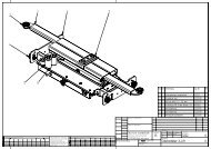
BOOMS<br />
BOOMS M100<br />
N. CODE DESCRIPTION QUANTITY<br />
10 01-0251 OUTSIDE ARM 2<br />
19 01-0250 INSIDE ARM 2<br />
22 02-4003 ROLLER 8<br />
23 03-3514 SELF LUBRICATING BUSHING- 35x39x40 8<br />
24 02-8002 ARM SETTING PIN 8<br />
25 03-3023 SNAP RING- 35 16<br />
26 03-3035 SELF LUBRICATING BUSHING 35x39x20 32<br />
27 02-8004 JOINT PIN 4<br />
29 01-0267 WASHER 25x51x3 8<br />
30 03-3020 SELF LOCKING NUT 8<br />
31 01-1244 HOSE PROTECTION 2<br />
27
BOOMS M200<br />
M200<br />
N.. CODE DESCRIPTION QUANTITY N. CODE DESCRIPTION QUANTITY<br />
10 01-0251 OUTSIDE ARM 4 23 03-3514 SELF LUBRICATING BUSHING 35x39x40 16<br />
19 01-0250 INSIDE ARM 4 25 03-3023 SNAP RING 35 32<br />
22 02-4003 ROLLER 16 27 02-8004 JOINT PIN 8<br />
24 02-8002 ARM SETTING PIN 16 30 03-3020 SELF-LOCKING NUT 16<br />
26 03-3035 SELF LUBRICATING BUSHING 35x39x20 64 29 01-0267 WASHER 25x52x3 16<br />
31 01-1244 HOSES PROTECTION 4<br />
29
BOOMS M300<br />
N CODE DESCRIPTION QUANTITY N. CODE DESCRIPTION QUANTITY<br />
10 01-0251 OUTSIDE ARM 6 23 03-3514 SELF LUBRICATING BUSHING 35x39x40 24<br />
19 01-0250 INSIDE ARM 6 25 03-3023 SNAP RING 35 48<br />
22 02-4003 ROLLER 24 27 02-8004 JOINT PIN 12<br />
24 02-8002 ARM SETTING PIN 24 30 03-3020 SELF-LOCKING NUT 24<br />
26 03-3035 SELF LUBRICATING BUSHING 35x39x20 96 29 01-0267 WASHER 25x52x3 24<br />
31 01-1244 HOSES PROTECTION 6<br />
30
BOOMS M 400<br />
N. CODE DESCRIPTION QUANTITY N CODE DESCRIPTION QUANTITY<br />
10 01-0251 RED OUTSIDE ARM 8 23 03-3514 SELF LUBRICATING BUSHING 35x39x40 32<br />
19 01-0250 RED INSIDE ARM 8 25 03-3023 SNAP RING 35 64<br />
22 02-4003 ROLLER 32 27 02-8004 JOINT PIN 16<br />
24 02-8002 ARM SETTING PIN 32 30 03-3020 SELF-LOCKING NUT 32<br />
26 03-3035 SELF LUBRICATING BUSHING 35x39x20 128 29 01-0267 WASHER 25x52x3 32<br />
31 01-1244 HOSES PROTECTION 8<br />
31
“ PISTONS-MECHANICAL SAFETY HYDRAULIC CONNECTIONS AND BLOCK”<br />
M 100<br />
N. CODE DESCRIPTION QUANTITY<br />
32 04-4500 P1 PISTON 2<br />
33 04-4501 P2 PISTON 2<br />
34 02-8001 SHORT PISTON PIN 6<br />
35 02-8000 LONG PISTON PIN 2<br />
36 03-3518 SNAP RING 45 16<br />
37 02-4004 HEXAGONAL HEAD SCREW 8<br />
38 02-4005 3/8 GAS H7mm. NUT 8<br />
39 02-0444 MECHANICAL SAFETY PISTON 2<br />
50 04-4200 P1 PISTON GASKET KIT 1<br />
51 04-4201 P2 PISTON GASKET KIT 1<br />
32
PISTONS-MECHANICAL SAFETY, HYDRAULIC CONNECTIONS AND BLOCK.<br />
M200<br />
FIRST SECTION<br />
SECOND SECTION<br />
M200<br />
N. CODE DESCRIPTION QUANTITY N. CODE DESCRIPTION QUANTITY<br />
32 04-4500 P1 PISTON 4 33 04-4501 P2 PISTON 4<br />
34 02-8001 SHORT PISTON PIN 12 35 02-8000 LONG PISTON PIN 4<br />
36 03-3518 SNAP RING 45 32 37 02-4004 HEXAGONAL HEAD SCREW 4<br />
38 02-4005 3/8 GAS NUTS 4 39 02-0444 MECHANICAL SAFETY PISTON 4<br />
40 02/8010 DELIVERY CONNECTION BLOCK 2 41 02/8011 CONNECTION BLOCK 2<br />
50 04-4200 P1 PISTON GASKET KIT 1 51 04-4201 P2 PISTON GASKET KIT 1<br />
158 01-0045 CLAMP 2<br />
33
. PISTONS-MECHANICAL SAFETY HYDRAULIC CONNECTIONS AND BLOCK<br />
M300<br />
PRIMA SEZIONE SECONDA SEZIONE TERZA SEZIONE<br />
M300<br />
N. CODE DESCRIPTION QUANTITY N. CODE DESCRIPTION QUANTITY<br />
32 04-4500 P1 PISTON 6 33 04-4501 P2 PISTON 6<br />
34 02-8001 SHORT PISTON PIN 18 35 02-8000 LONG PISTON PIN 6<br />
36 03-3518 SNAP RING 45 48 37 02-4004 HEXAGONAL HEAD SCREW 4<br />
38 02-4005 3/8 GAS NUTS 4 39 02-0444 MECHANICAL SAFETY PISTON 6<br />
42 02/8012 DELIVERY CONNECTION BLOCK 4 43 02/8013 CONNECTION BLOCK 4<br />
50 04-4200 P1 PISTON GASKET KIT 1 51 04-4201 P2 PISTON GASKET KIT 1<br />
158 01-0045 CLAMP 2<br />
34
PISTONS-MECHANICAL SAFETY HYDRAULIC CONNECTIONS AND BLOCK<br />
M400<br />
FIRST SECTION SECOND SECTION THIRD SECTION FOURTH SECTION<br />
M400<br />
N. CODE DESCRIPTION QUANTITY N. CODE DESCRIPTION QUANTITY<br />
32 04-4500 P1 PISTON 8 33 04-4501 P2 PISTON 8<br />
34 02-8001 SHORT PISTON PIN 24 35 02-8000 LONG PISTON PIN 8<br />
36 03-3518 SNAP RING 45 64 37 02-4004 HEXAGONAL HEAD SCREW 4<br />
38 02-4005 3/8 GAS NUTS 4 39 02-0444 MECHANICAL SAFETY PISTON 8<br />
44 02-8014 HYDRAULIC CONNECTION BLOCK 2 45 02-8015 HYDRAULIC CONNECTION BLOCK 2<br />
46 02-8016 HYDRAULIC CONNECTION BLOCK 2 50 04-4201 P1 PISTON GASKET KIT 1<br />
51 04-4200 P2 PISTON GASKET KIT 1 158 01-0045 CLAMP 2<br />
FIRST SECTION DETAIL HYDRAULIC CONNECTION BLOCK CLAMP DETAIL<br />
35
PLATFORM M100<br />
M100-PLATFORM<br />
N. CODE DESCRIPTION QUANTITY<br />
47 01-0012 P1 PLATFORM 1<br />
53 01-0013 P2 PLATFORM 1<br />
52 01-0231 FOOTGUARD 4<br />
M200<br />
M200-PLATFORM<br />
N. CODE DESCRIPTION QUANTITY<br />
56 01-0352 P1 PLATFORM 1<br />
59 01-0353 P2 PLATFORM 1<br />
62 01-1071 FOOTGUARD 4<br />
PLATFORM M300<br />
N. CODE DESCRIPTION QUANTITY<br />
62 01-0019 P1 PLATFORM 1<br />
65 01-0020 P2 PLATFORM 1<br />
68 01-1070 FOOTGUARD 6<br />
36
M400<br />
N. CODE DESCRIPTION QUANTITY<br />
69 01-0021 P1 FIRST PART PLATFORM 1<br />
76 01-0022 P1 SECOND PART PLATFORM 1<br />
72 01-0023 P2 FIRST PART PLATFORM 1<br />
79 01-0024 P2 SECOND PART PLATFORM 1<br />
75 01-1053 FOOTGUARD 6<br />
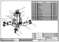
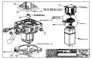
CONTROL BOX. M100<br />
N. CODE DESCRIPTION QUANTITY<br />
82 01-1123 CABINET 1<br />
85 01-1124 FRONT DOOR 1<br />
88 01-1125 SIDE DOOR 1<br />
91 06-6002 GENERAL SWITCH 1<br />
92 06-6012 FINISHING ACCESSORIES 1<br />
93 06-6003 SIGNAL LIGHT 1<br />
94 06-6004 PROTECTION CAPS 1<br />
95 06-6005 SIGNAL LIGHT LAMP 1<br />
96 06-6006 PROTECTED PUSHBUTTON 3<br />
97 06-6007 CONTACTOR PUSHBUTTON COVER 3<br />
98 06-6009 CONTACT ELEMENT 5<br />
99 N.C. FULL ELECTRIC CARD 1<br />
100 06-6509 LIGHT SELECTOR 1<br />
101 04-4109 PUMP MOTOR UNIT 1<br />
102 04-4549 ELECTROVALVES BLOCK 1<br />
103 04-4020 PET COCK 1<br />
104 01-0254 OIL TANK 1<br />
105 04-4024 TANK CAP 1<br />
106 06-6116 THREE-PHASE MOTOR 1<br />
107 05-5514 AIR ELECTROVALVE CAP 1<br />
108 05-5512 UNION ELBOW 90° 1/8 RATIO 2<br />
109 05-5000 AIR ELECTROVALVE. 1<br />
37
CONTROL BOX M200-300-400<br />
M300<br />
M400<br />
CONTROL BOX 200-300-400<br />
MODELS-QUANTITY<br />
N. CODE DESCRIPTION M200 M300 M400<br />
110 01-0270 RED CABINET 1 1 1<br />
113 01-0016 RED FRONT DOOR 1 1 1<br />
116 01-0017 RED SIDE DOOR 1 1 1<br />
91 06-6002 GENERAL SWITCH 1 1 1<br />
92 06-6012 FINISHING ACCESSORIES 1 1 1<br />
93 06-6003 SIGNAL LIGHT 1 1 1<br />
94 06-6004 PROTECTION CAPS 1 1 1<br />
95 06-6005 SIGNAL LIGHT LAMP 1 1 1<br />
96 06-6006 PROTECTED PUSH BUTTON 3 3 3<br />
97 06-6007 ACTUATOR 3 3 3<br />
98 06-6009 CONTACT ELEMENT 5 5 5<br />
119 COMPLETE ELECTRIC CARD 1<br />
120 COMPLETE ELECTRIC CARD 1<br />
121 COMPLETE ELECTRIC CARD 1<br />
100 06-6509 LIGHT SELECTOR 1 1 1<br />
122 04-4558 PUMP MOTOR UNIT 1<br />
123 04-4558 PUMP MOTOR UNIT 1<br />
124 LEVEL ELECTROVALVE BLOCK 1<br />
125 LEVEL ELECTROVALVE BLOCK 1<br />
103 04-4020 LEVELLING COCK 1 1 1<br />
126 DISCHARGE COCK 1 2 2<br />
127 01-1049 OIL TANK 1 1<br />
105 04-4024 OIL TANK CAP 1 1 1<br />
128 06-6102 THREE-PHASE MOTOR 1<br />
129 06-6720 THREE-PHASE MOTOR 1<br />
130 PRESSURE ELECTROVALVE BLOCK 1 1 2<br />
132 04-4558 PUMP MOTOR UNIT 2<br />
131 06-6102 THREE-PHASE MOTOR 2<br />
133 THREE-PHASE MOTOR 2<br />
134 OIL TANK 1<br />
38
ELECTRIC CARD<br />
MIRACH 100<br />
MIRACH 200-300 MIRACH 400<br />
ELECTRIC CARD SPARE PARTS<br />
N. CODE DESCRIPTION<br />
136 06-6010 50VA SINGLE PHASE TRANSFORMER<br />
137 06-6596 300VA SINGLE PHASE TRANSFORMER<br />
139 06-6011 CA 4-9-10 24VA CONTACTOR<br />
140 06-6013 24 VAC 4 SC. RELAY<br />
141 06-6014 RELAY BASE 4SC<br />
142 06-6016 5X20 2A FUSE<br />
143 06-6017 5X20 500mA FUSE<br />
144 06-6018 PRINTED CARDBOARD 006<br />
145 06-6520 24 VDC 1 SC. RELAY<br />
146 06-6523 VERTICAL FUSE CARRIER<br />
147 06-6537 WEBER 20A FUSE<br />
148 06-6020 RELAY BASE 1SC<br />
149 06-6536 TRIPOLAR FUSE CARRIER 25A<br />
150 06-0304 TRIPOLAR FUSE CARRIER 32A<br />
151 06-6667 BIPOLAR FUSE CARRIER 32A<br />
152 06-0306 MOTOR CONTACTOR 11 KW<br />
153 06-6011 MOTOR CONTACTOR CA 4-9-10<br />
154 06-6620 RELAY BASE 24 AC<br />
155 06-6542 5A 24AC 2 SC. RELAY<br />
156 06-0102 32A FUSE<br />
157 06-6525 4A FUSE<br />
39
SCISSOR LIFT WITH PLATFORM<br />
MAINTENANCE BOOK<br />
MIRACH HEAVY-DUTY SCISSOR LIFT<br />
INITIAL TEST<br />
N. DESCRIPTION TEST YES NO Notes<br />
1 Floor consistency check <br />
2 Safety distances check (from walls, columns, ceiling, other machines etc.) <br />
3 Power supply line check. <br />
4 Pneumatic supply line check. <br />
5 Lift levelling check. <br />
6 Lift working check. <br />
7 Mechanical safeties check. <br />
8 Electric safeties check. <br />
9 Loaded lift check. <br />
10 Lift fixing check. <br />
11 Oil level check. <br />
12 Hydraulic failure check. <br />
13 Pneumatic failure check. <br />
14 Operating instruction <br />
NOTES<br />
Installer<br />
User<br />
Stamp and signature<br />
Stamp and signature<br />
Date<br />
Next test on:<br />
40
RECURRING OR OCCASIONAL VISIT<br />
N. DESCRIPTION OF TEST YES NO Notes<br />
1 Lift maintenance and cleaning check. <br />
2 Mechanical safeties check. <br />
3 Electric safeties check. <br />
4 Oil level check. <br />
5 Rollers slides greasing. <br />
6 Movable parts greasing. <br />
7 High pressure flexible pipes check. <br />
8 Hydraulic failure check. <br />
9 Pneumatic failure check. <br />
10 Lift levelling check. <br />
11 Loaded lift check. <br />
NOTES<br />
Result of visit Positive <br />
Negative<br />
<br />
Installer<br />
User<br />
Stamp and signature<br />
Stamp and signature<br />
Date<br />
Next test on<br />
41
TESTS TO BE MADE BY THE USER<br />
TESTS DURING USE<br />
1 Levelling check.<br />
2 Hydraulic failure check.<br />
3 Pneumatic failure check.<br />
4 Safety devices check.<br />
MONTLY TESTS<br />
1 Lift through cleaning.<br />
2 Rollers slides check.<br />
3 Cylinders air bleeding (if necessary).<br />
HALF-YEARLY TESTS<br />
1 Oil level check.<br />
2 High pressure flexible pipes check.<br />
IN CASE OF IRREGULARITIES, STOP THE LIFT AND<br />
CONTACT OUR SERVICE DEPARTEMENT IMMEDIATELY<br />
42
REPAIR<br />
FAILURE<br />
ACTION<br />
Date<br />
Stamp and signature<br />
REPAIR<br />
FAILURE<br />
ACTION<br />
Date<br />
Stamp and signature<br />
MAY 1999 BY THE GRAPHIC DEPARTEMENT<br />
(G.A.)<br />
MARTE s.r.l. Via Custoza 15, 66013 Chieti Scalo ITALY. Tel. 0871/574008-Fax 0871/574092<br />
43