Lab 2.5.1: Basic PPP Configuration Lab
Lab 2.5.1: Basic PPP Configuration Lab
Lab 2.5.1: Basic PPP Configuration Lab

Create successful ePaper yourself
Turn your PDF publications into a flip-book with our unique Google optimized e-Paper software.
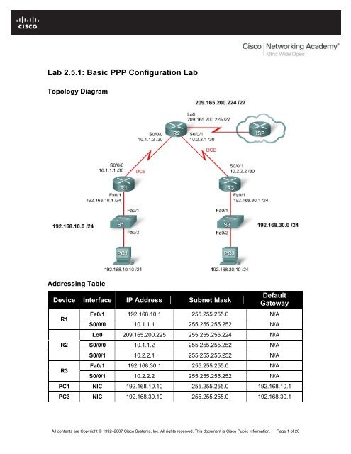
<strong>Lab</strong> <strong>2.5.1</strong>: <strong>Basic</strong> <strong>PPP</strong> <strong>Configuration</strong> <strong>Lab</strong><br />
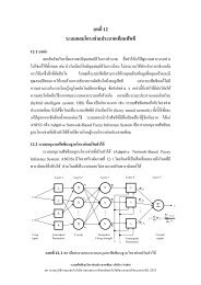
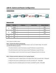
Topology Diagram<br />
Addressing Table<br />
Device Interface IP Address Subnet Mask<br />
R1<br />
R2<br />
R3<br />
Default<br />
Gateway<br />
Fa0/1 192.168.10.1 255.255.255.0 N/A<br />
S0/0/0 10.1.1.1 255.255.255.252 N/A<br />
Lo0 209.165.200.225 255.255.255.224 N/A<br />
S0/0/0 10.1.1.2 255.255.255.252 N/A<br />
S0/0/1 10.2.2.1 255.255.255.252 N/A<br />
Fa0/1 192.168.30.1 255.255.255.0 N/A<br />
S0/0/1 10.2.2.2 255.255.255.252 N/A<br />
PC1 NIC 192.168.10.10 255.255.255.0 192.168.10.1<br />
PC3 NIC 192.168.30.10 255.255.255.0 192.168.30.1<br />
All contents are Copyright © 1992–2007 Cisco Systems, Inc. All rights reserved. This document is Cisco Public Information. Page 1 of 20
CCNA Exploration<br />
Accessing the WAN: <strong>PPP</strong><br />
<strong>Lab</strong> <strong>2.5.1</strong>: <strong>Basic</strong> <strong>PPP</strong> <strong>Configuration</strong> <strong>Lab</strong><br />
Learning Objectives<br />
Upon completion of this lab, you will be able to:<br />
• Cable a network according to the topology diagram.<br />
• Erase the startup configuration and reload a router to the default state.<br />
• Perform basic configuration tasks on a router.<br />
• Configure and activate interfaces.<br />
• Configure OSPF routing on all routers.<br />
• Configure <strong>PPP</strong> encapsulation on all serial interfaces.<br />
• Learn about the debug ppp negotiation and debug ppp packet commands.<br />
• Learn how to change the encapsulation on the serial interfaces from <strong>PPP</strong> to HDLC.<br />
• Intentionally break and restore <strong>PPP</strong> encapsulation.<br />
• Configure <strong>PPP</strong> PAP and CHAP authentication.<br />
• Intentionally break and restore <strong>PPP</strong> PAP and CHAP authentication.<br />
Scenario<br />
In this lab, you will learn how to configure <strong>PPP</strong> encapsulation on serial links using the network<br />
shown in the topology diagram. You will also learn how to restore serial links to their default<br />
HDLC encapsulation. Pay special attention to what the output of the router looks like when you<br />
intentionally break <strong>PPP</strong> encapsulation. This will assist you in the Troubleshooting lab associated<br />
with this chapter. Finally, you will configure <strong>PPP</strong> PAP authentication and <strong>PPP</strong> CHAP<br />
authentication.<br />
Task 1: Prepare the Network<br />
Step 1: Cable a network that is similar to the one in the topology diagram.<br />
You can use any current router in your lab as long as it has the required interfaces shown in the<br />
topology diagram.<br />
Note: If you use 1700, 2500, or 2600 routers, the router outputs and interface descriptions appear<br />
differently.<br />
Step 2: Clear any existing configurations on the routers.<br />
Task 2: Perform <strong>Basic</strong> Router <strong>Configuration</strong><br />
Configure the R1, R2, and R3 routers according to the following guidelines:<br />
• Configure the router hostname.<br />
• Disable DNS lookup.<br />
• Configure an EXEC mode password.<br />
• Configure a message-of-the-day banner.<br />
• Configure a password for console connections.<br />
All contents are Copyright © 1992–2007 Cisco Systems, Inc. All rights reserved. This document is Cisco Public Information. Page 2 of 20
CCNA Exploration<br />
Accessing the WAN: <strong>PPP</strong><br />
<strong>Lab</strong> <strong>2.5.1</strong>: <strong>Basic</strong> <strong>PPP</strong> <strong>Configuration</strong> <strong>Lab</strong><br />
• Configure synchronous logging.<br />
• Configure a password for vty connections.<br />
Task 3: Configure and Activate Serial and Ethernet Addresses<br />
Step 1: Configure interfaces on R1, R2, and R3.<br />
Configure the interfaces on the R1, R2, and R3 routers with the IP addresses from the addressing<br />
table at the beginning of the lab. Be sure to include the clock rate on the serial DCE interfaces.<br />
Step 2: Verify IP addressing and interfaces.<br />
Use the show ip interface brief command to verify that the IP addressing is correct and that the<br />
interfaces are active.<br />
When you have finished, be sure to save the running configuration to the NVRAM of the router.<br />
Step 3: Configure the Ethernet interfaces of PC1 and PC3.<br />
Configure the Ethernet interfaces of PC1 and PC3 with the IP addresses and default gateways<br />
from the addressing table.<br />
Step 4: Test the configuration by pinging the default gateway from the PC.<br />
Task 4: Configure OSPF on the Routers<br />
If you need to review the OSPF commands, see Exploration 2, module 11.<br />
Step 1: Enable OSPF routing on R1, R2, and R3.<br />
Use the router ospf command with a process ID of 1. Be sure to advertise the networks.<br />
R1(config)#router ospf 1<br />
R1(config-router)#network 192.168.10.0 0.0.0.255 area 0<br />
R1(config-router)#network 10.1.1.0 0.0.0.3 area 0<br />
*Aug 17 17:49:14.689: %OSPF-5-ADJCHG: Process 1, Nbr 209.165.200.225 on<br />
Serial0/0/0 from LOADING to FULL, Loading Done<br />
R1(config-router)#<br />
R2(config)#router ospf 1<br />
R2(config-router)#network 10.1.1.0 0.0.0.3 area 0<br />
*Aug 17 17:48:40.645: %OSPF-5-ADJCHG: Process 1, Nbr 192.168.10.1 on<br />
Serial0/0/0 from LOADING to FULL, Loading Done<br />
R2(config-router)#network 10.2.2.0 0.0.0.3 area 0<br />
R2(config-router)#network 209.165.200.224 0.0.0.31 area 0<br />
R2(config-router)#<br />
*Aug 17 17:57:44.729: %OSPF-5-ADJCHG: Process 1, Nbr 192.168.30.1 on<br />
Serial0/0/1 from LOADING to FULL, Loading Done<br />
R2(config-router)#<br />
R3(config)#router ospf 1<br />
R3(config-router)#network 10.2.2.0 0.0.0.3 area 0<br />
*Aug 17 17:58:02.017: %OSPF-5-ADJCHG: Process 1, Nbr 209.165.200.225 on<br />
Serial0/0/1 from LOADING to FULL, Loading Done<br />
R3(config-router)#network 192.168.30.0 0.0.0.255 area 0<br />
R3(config-router)#<br />
All contents are Copyright © 1992–2007 Cisco Systems, Inc. All rights reserved. This document is Cisco Public Information. Page 3 of 20
CCNA Exploration<br />
Accessing the WAN: <strong>PPP</strong><br />
<strong>Lab</strong> <strong>2.5.1</strong>: <strong>Basic</strong> <strong>PPP</strong> <strong>Configuration</strong> <strong>Lab</strong><br />
Step 2: Verify that you have full network connectivity.<br />
Use the show ip route and ping commands to verify connectivity.<br />
R1#show ip route<br />
<br />
O<br />
C<br />
O<br />
O<br />
C<br />
192.168.30.0/24 [110/1563] via 10.1.1.2, 00:33:56, Serial0/0/0<br />
192.168.10.0/24 is directly connected, FastEthernet0/1<br />
209.165.200.0/27 is subnetted, 1 subnets<br />
209.165.200.225 [110/782] via 10.1.1.2, 00:33:56, Serial0/0/0<br />
10.0.0.0/8 is variably subnetted, 3 subnets, 2 masks<br />
10.2.2.0/30 [110/1562] via 10.1.1.2, 00:33:56, Serial0/0/0<br />
10.1.1.0/30 is directly connected, Serial0/0/0<br />
R1#ping 192.168.30.1<br />
Type escape sequence to abort.<br />
Sending 5, 100-byte ICMP Echos to 192.168.30.1, timeout is 2 seconds:<br />
!!!!!<br />
Success rate is 100 percent (5/5), round-trip min/avg/max = 32/32/32 ms<br />
R1#<br />
R2#show ip route<br />
<br />
O<br />
O<br />
C<br />
C<br />
C<br />
192.168.30.0/24 [110/782] via 10.2.2.2, 00:33:04, Serial0/0/1<br />
192.168.10.0/24 [110/782] via 10.1.1.1, 00:33:04, Serial0/0/0<br />
209.165.200.0/27 is subnetted, 1 subnets<br />
209.165.200.224 is directly connected, Loopback0<br />
10.0.0.0/8 is variably subnetted, 4 subnets, 2 masks<br />
10.2.2.0/30 is directly connected, Serial0/0/1<br />
10.1.1.0/30 is directly connected, Serial0/0/0<br />
R2#ping 192.168.30.1<br />
Type escape sequence to abort.<br />
Sending 5, 100-byte ICMP Echos to 192.168.30.1, timeout is 2 seconds:<br />
!!!!!<br />
Success rate is 100 percent (5/5), round-trip min/avg/max = 16/16/16 ms<br />
R2#ping 192.168.10.1<br />
Type escape sequence to abort.<br />
Sending 5, 100-byte ICMP Echos to 192.168.10.1, timeout is 2 seconds:<br />
!!!!!<br />
Success rate is 100 percent (5/5), round-trip min/avg/max = 16/16/16 ms<br />
R2#<br />
R3#show ip route<br />
<br />
C<br />
O<br />
192.168.30.0/24 is directly connected, FastEthernet0/1<br />
192.168.10.0/24 [110/1563] via 10.2.2.1, 00:32:01, Serial0/0/1<br />
209.165.200.0/27 is subnetted, 1 subnets<br />
All contents are Copyright © 1992–2007 Cisco Systems, Inc. All rights reserved. This document is Cisco Public Information. Page 4 of 20
CCNA Exploration<br />
Accessing the WAN: <strong>PPP</strong><br />
<strong>Lab</strong> <strong>2.5.1</strong>: <strong>Basic</strong> <strong>PPP</strong> <strong>Configuration</strong> <strong>Lab</strong><br />
O<br />
C<br />
O<br />
209.165.200.225 [110/782] via 10.2.2.1, 00:32:01, Serial0/0/1<br />
10.0.0.0/8 is variably subnetted, 3 subnets, 2 masks<br />
10.2.2.0/30 is directly connected, Serial0/0/1<br />
10.1.1.0/30 [110/1562] via 10.2.2.1, 00:32:01, Serial0/0/1<br />
R3#ping 209.165.200.225<br />
Type escape sequence to abort.<br />
Sending 5, 100-byte ICMP Echos to 209.165.200.225, timeout is 2<br />
seconds:<br />
!!!!!<br />
Success rate is 100 percent (5/5), round-trip min/avg/max = 16/16/16 ms<br />
R3#ping 192.168.10.1<br />
Type escape sequence to abort.<br />
Sending 5, 100-byte ICMP Echos to 192.168.10.1, timeout is 2 seconds:<br />
!!!!!<br />
Success rate is 100 percent (5/5), round-trip min/avg/max = 32/32/32 ms<br />
R3#<br />
Task 5: Configure <strong>PPP</strong> Encapsulation on Serial Interfaces<br />
Step 1: Use the show interface command to check whether HDLC is the default serial<br />
encapsulation.<br />
R1#show interface serial0/0/0<br />
Serial0/0/0 is up, line protocol is up<br />
Hardware is GT96K Serial<br />
Internet address is 10.1.1.1/30<br />
MTU 1500 bytes, BW 128 Kbit, DLY 20000 usec,<br />
reliability 255/255, txload 1/255, rxload 1/255<br />
Encapsulation HDLC, loopback not set<br />
<br />
R2#show interface serial 0/0/0<br />
Serial0/0/0 is up, line protocol is up<br />
Hardware is GT96K Serial<br />
Internet address is 10.1.1.2/30<br />
MTU 1500 bytes, BW 128 Kbit, DLY 20000 usec,<br />
reliability 255/255, txload 1/255, rxload 1/255<br />
Encapsulation HDLC, loopback not set<br />
<br />
R2#show interface serial 0/0/1<br />
Serial0/0/1 is up, line protocol is up<br />
Hardware is GT96K Serial<br />
Internet address is 10.2.2.1/30<br />
MTU 1500 bytes, BW 128 Kbit, DLY 20000 usec,<br />
reliability 255/255, txload 1/255, rxload 1/255<br />
Encapsulation HDLC, loopback not set<br />
<br />
All contents are Copyright © 1992–2007 Cisco Systems, Inc. All rights reserved. This document is Cisco Public Information. Page 5 of 20
CCNA Exploration<br />
Accessing the WAN: <strong>PPP</strong><br />
<strong>Lab</strong> <strong>2.5.1</strong>: <strong>Basic</strong> <strong>PPP</strong> <strong>Configuration</strong> <strong>Lab</strong><br />
R3#show interface serial 0/0/1<br />
Serial0/0/1 is up, line protocol is up<br />
Hardware is GT96K Serial<br />
Internet address is 10.2.2.2/30<br />
MTU 1500 bytes, BW 128 Kbit, DLY 20000 usec,<br />
reliability 255/255, txload 1/255, rxload 1/255<br />
Encapsulation HDLC, loopback not set<br />
<br />
Step 2: Use debug commands on R1 and R2 to see the effects of configuring <strong>PPP</strong>.<br />
R1#debug ppp negotiation<br />
<strong>PPP</strong> protocol negotiation debugging is on<br />
R1#debug ppp packet<br />
<strong>PPP</strong> packet display debugging is on<br />
R1#<br />
R2#debug ppp negotiation<br />
<strong>PPP</strong> protocol negotiation debugging is on<br />
R2#debug ppp packet<br />
<strong>PPP</strong> packet display debugging is on<br />
R2#<br />
Step 3: Change the encapsulation of the serial interfaces from HDLC to <strong>PPP</strong>.<br />
Change the encapsulation type on the link between R1 and R2, and observe the effects. If you<br />
start to receive too much debug data, use the undebug all command to turn debugging off.<br />
R1(config)#interface serial 0/0/0<br />
R1(config-if)#encapsulation ppp<br />
R1(config-if)#<br />
*Aug 17 19:02:53.412: %OSPF-5-ADJCHG: Process 1, Nbr 209.165.200.225 on<br />
Serial0/0/0 from FULL to DOWN, Neighbor Down: Interface down or<br />
detached<br />
R1(config-if)#<br />
*Aug 17 19:02:53.416: Se0/0/0 <strong>PPP</strong>: Phase is DOWN, Setup<br />
*Aug 17 19:02:53.416: Se0/0/0 <strong>PPP</strong>: Using default call direction<br />
*Aug 17 19:02:53.416: Se0/0/0 <strong>PPP</strong>: Treating connection as a dedicated<br />
line<br />
*Aug 17 19:02:53.416: Se0/0/0 <strong>PPP</strong>: Session handle[E4000001] Session<br />
id[0]<br />
*Aug 17 19:02:53.416: Se0/0/0 <strong>PPP</strong>: Phase is ESTABLISHING, Active Open<br />
*Aug 17 19:02:53.424: Se0/0/0 LCP: O CONFREQ [Closed] id 1 len 10<br />
*Aug 17 19:02:53.424: Se0/0/0 LCP: MagicNumber 0x63B994DE<br />
(0x050663B994DE)<br />
R1(config-if)#<br />
*Aug 17 19:02:55.412: Se0/0/0 <strong>PPP</strong>: Outbound cdp packet dropped<br />
*Aug 17 19:02:55.432: Se0/0/0 LCP: TIMEout: State REQsent<br />
*Aug 17 19:02:55.432: Se0/0/0 LCP: O CONFREQ [REQsent] id 2 len 10<br />
*Aug 17 19:02:55.432: Se0/0/0 LCP: MagicNumber 0x63B994DE<br />
(0x050663B994DE)<br />
*Aug 17 19:02:56.024: Se0/0/0 <strong>PPP</strong>: I pkt type 0x008F, datagramsize 24<br />
link[illegal]<br />
*Aug 17 19:02:56.024: Se0/0/0 UNKNOWN(0x008F): Non-NCP packet,<br />
discarding<br />
R1(config-if)#<br />
All contents are Copyright © 1992–2007 Cisco Systems, Inc. All rights reserved. This document is Cisco Public Information. Page 6 of 20
CCNA Exploration<br />
Accessing the WAN: <strong>PPP</strong><br />
<strong>Lab</strong> <strong>2.5.1</strong>: <strong>Basic</strong> <strong>PPP</strong> <strong>Configuration</strong> <strong>Lab</strong><br />
*Aug 17 19:02:57.252: Se0/0/0 <strong>PPP</strong>: I pkt type 0x000F, datagramsize 84<br />
link[illegal]<br />
*Aug 17 19:02:57.252: Se0/0/0 UNKNOWN(0x000F): Non-NCP packet,<br />
discarding<br />
*Aug 17 19:02:57.448: Se0/0/0 LCP: TIMEout: State REQsent<br />
*Aug 17 19:02:57.448: Se0/0/0 LCP: O CONFREQ [REQsent] id 3 len 10<br />
*Aug 17 19:02:57.448: Se0/0/0 LCP: MagicNumber 0x63B994DE<br />
(0x050663B994DE)<br />
R1(config-if)#<br />
*Aug 17 19:02:58.412: %LINEPROTO-5-UPDOWN: Line protocol on Interface<br />
Serial0/0/0, changed state to down<br />
R2(config)#interface serial 0/0/0<br />
R2(config-if)#encapsulation ppp<br />
R2(config-if)#<br />
*Aug 17 19:06:48.848: Se0/0/0 <strong>PPP</strong>: Phase is DOWN, Setup<br />
*Aug 17 19:06:48.848: Se0/0/0 <strong>PPP</strong>: Using default call direction<br />
*Aug 17 19:06:48.848: Se0/0/0 <strong>PPP</strong>: Treating connection as a dedicated<br />
line<br />
*Aug 17 19:06:48.848: Se0/0/0 <strong>PPP</strong>: Session handle[C6000001] Session<br />
id[0]<br />
*Aug 17 19:06:48.848: Se0/0/0 <strong>PPP</strong>: Phase is ESTABLISHING, Active Open<br />
*Aug 17 19:06:48.856: Se0/0/0 LCP: O CONFREQ [Closed] id 1 len 10<br />
*Aug 17 19:06:48.856: Se0/0/0 LCP: MagicNumber 0x63BD388C<br />
(0x050663BD388C)<br />
*Aug 17 19:06:48.860: Se0/0/0 <strong>PPP</strong>: I pkt type 0xC021, datagramsize 14<br />
link[ppp]<br />
*Aug 17 19:06:48.860: Se0/0/0 LCP: I CONFACK [REQsent] id 1 len 10<br />
R2(config-if)#<br />
*Aug 17 19:06:48.860: Se0/0/0 LCP: MagicNumber 0x63BD388C<br />
(0x050663BD388C)<br />
R2(config-if)#<br />
*Aug 17 19:06:50.864: Se0/0/0 LCP: TIMEout: State ACKrcvd<br />
*Aug 17 19:06:50.864: Se0/0/0 LCP: O CONFREQ [ACKrcvd] id 2 len 10<br />
*Aug 17 19:06:50.864: Se0/0/0 LCP: MagicNumber 0x63BD388C<br />
(0x050663BD388C)<br />
*Aug 17 19:06:50.868: Se0/0/0 <strong>PPP</strong>: I pkt type 0xC021, datagramsize 14<br />
link[ppp]<br />
*Aug 17 19:06:50.868: Se0/0/0 LCP: I CONFREQ [REQsent] id 61 len 10<br />
*Aug 17 19:06:50.868: Se0/0/0 LCP: MagicNumber 0x63BDB9A8<br />
(0x050663BDB9A8)<br />
*Aug 17 19:06:50.868: Se0/0/0 LCP: O CONFACK [REQsent] id 61 len 10<br />
*Aug 17 19:06:50.868: Se0/0/0 LCP: MagicNumber 0x63BDB9A8<br />
(0x050663BDB9A8)<br />
*Aug 17 19:06:50.868: Se0/0/0 <strong>PPP</strong>: I pkt type 0xC021, datagramsize 14<br />
link[ppp]<br />
*Aug 17 19:06:50.868: Se0/0/0 LCP: I CONFACK [ACKsent] id 2 len 10<br />
*Aug 17 19:06:50.868: Se0/0/0 LCP: MagicNumber 0x63BD388C<br />
(0x050663BD388C)<br />
*Aug 17 19:06:50.868: Se0/0/0 LCP: State is Open<br />
*Aug 17 19:06:50.872: Se0/0/0 <strong>PPP</strong>: Phase is FORWARDING, Attempting<br />
Forward<br />
*Aug 17 19:06:50.872: Se0/0/0 <strong>PPP</strong>: Phase is ESTABLISHING, Finish LCP<br />
*Aug 17 19:06:50.872: Se0/0/0 <strong>PPP</strong>: Phase is UP<br />
*Aug 17 19:06:50.872: Se0/0/0 IPCP: O CONFREQ [Closed] id 1 len 10<br />
*Aug 17 19:06:50.872: Se0/0/0 IPCP: Address 10.1.1.2<br />
All contents are Copyright © 1992–2007 Cisco Systems, Inc. All rights reserved. This document is Cisco Public Information. Page 7 of 20
CCNA Exploration<br />
Accessing the WAN: <strong>PPP</strong><br />
<strong>Lab</strong> <strong>2.5.1</strong>: <strong>Basic</strong> <strong>PPP</strong> <strong>Configuration</strong> <strong>Lab</strong><br />
(0x03060A010102)<br />
*Aug 17 19:06:50.872: Se0/0/0 CDPCP: O CONFREQ [Closed] id 1 len 4<br />
*Aug 17 19:06:50.872: Se0/0/0 <strong>PPP</strong>: Process pending ncp packets<br />
*Aug 17 19:06:50.876: Se0/0/0 <strong>PPP</strong>: I pkt type 0x8021, datagramsize 14<br />
link[ip]<br />
*Aug 17 19:06:50.876: Se0/0/0 IPCP: I CONFREQ [REQsent] id 1 len 10<br />
*Aug 17 19:06:50.876: Se0/0/0 IPCP: Address 10.1.1.1<br />
(0x03060A010101)<br />
*Aug 17 19:06:50.876: Se0/0/0 <strong>PPP</strong>: I pkt type 0x8207, datagramsize 8<br />
link[cdp]<br />
*Aug 17 19:06:50.876: Se0/0/0 IPCP: O CONFACK [REQsent] id 1 len 10<br />
*Aug 17 19:06:50.876: Se0/0/0 IPCP: Address 10.1.1.1<br />
(0x03060A010101)<br />
*Aug 17 19:06:50.876: Se0/0/0 CDPCP: I CONFREQ [REQsent] id 1 len 4<br />
*Aug 17 19:06:50.876: Se0/0/0 CDPCP: O CONFACK [REQsent] id 1 len 4<br />
*Aug 17 19:06:50.876: Se0/0/0 <strong>PPP</strong>: I pkt type 0x8021, datagramsize 14<br />
link[ip]<br />
*Aug 17 19:06:50.876: Se0/0/0 IPCP: I CONFACK [ACKse<br />
R2(config-if)#nt] id 1 len 10<br />
*Aug 17 19:06:50.876: Se0/0/0 IPCP: Address 10.1.1.2<br />
(0x03060A010102)<br />
*Aug 17 19:06:50.876: Se0/0/0 IPCP: State is Open<br />
*Aug 17 19:06:50.876: Se0/0/0 <strong>PPP</strong>: I pkt type 0x8207, datagramsize 8<br />
link[cdp]<br />
*Aug 17 19:06:50.876: Se0/0/0 IPCP: Install route to 10.1.1.1<br />
*Aug 17 19:06:50.880: Se0/0/0 CDPCP: I CONFACK [ACKsent] id 1 len 4<br />
*Aug 17 19:06:50.880: Se0/0/0 CDPCP: State is Open<br />
*Aug 17 19:06:50.880: Se0/0/0 <strong>PPP</strong>: O pkt type 0x0021, datagramsize 80<br />
*Aug 17 19:06:50.880: Se0/0/0 IPCP: Add link info for cef entry<br />
10.1.1.1<br />
*Aug 17 19:06:50.884: Se0/0/0 <strong>PPP</strong>: I pkt type 0x0021, datagramsize 80<br />
link[ip]<br />
*Aug 17 19:06:51.848: %LINEPROTO-5-UPDOWN: Line protocol on Interface<br />
Serial0/0/0, changed state to up<br />
R2(config-if)#<br />
*Aug 17 19:06:51.888: Se0/0/0 LCP-FS: I ECHOREQ [Open] id 1 len 12<br />
magic 0x63BDB9A8<br />
*Aug 17 19:06:51.888: Se0/0/0 LCP-FS: O ECHOREP [Open] id 1 len 12<br />
magic 0x63BD388C<br />
<br />
*Aug 17 19:07:00.936: %OSPF-5-ADJCHG: Process 1, Nbr 192.168.10.1 on<br />
Serial0/0/0 from LOADING to FULL, Loading Done<br />
What happens when one end of the serial link is encapsulated with <strong>PPP</strong> and the other<br />
end of the link is encapsulated with HDLC<br />
_____________________________________________________________________<br />
_____________________________________________________________________<br />
_____________________________________________________________________<br />
All contents are Copyright © 1992–2007 Cisco Systems, Inc. All rights reserved. This document is Cisco Public Information. Page 8 of 20
CCNA Exploration<br />
Accessing the WAN: <strong>PPP</strong><br />
<strong>Lab</strong> <strong>2.5.1</strong>: <strong>Basic</strong> <strong>PPP</strong> <strong>Configuration</strong> <strong>Lab</strong><br />
What steps does <strong>PPP</strong> go through when the other end of the serial link on R2 is<br />
configured with <strong>PPP</strong> encapsulation<br />
_____________________________________________________________________<br />
_____________________________________________________________________<br />
_____________________________________________________________________<br />
_____________________________________________________________________<br />
_____________________________________________________________________<br />
_____________________________________________________________________<br />
What happens when <strong>PPP</strong> encapsulation is configured on each end of the serial link<br />
_____________________________________________________________________<br />
_____________________________________________________________________<br />
Step 4: Turn off debugging.<br />
Turn off debugging if you have not already used the undebug all command.<br />
R1#undebug all<br />
Port Statistics for unclassified packets is not turned on.<br />
All possible debugging has been turned off<br />
R1#<br />
R2#undebug all<br />
Port Statistics for unclassified packets is not turned on.<br />
All possible debugging has been turned off<br />
R2#<br />
Step 5: Change the encapsulation from HDLC to <strong>PPP</strong> on both ends of the serial link<br />
between R2 and R3.<br />
R2(config)#interface serial0/0/1<br />
R2(config-if)#encapsulation ppp<br />
R2(config-if)#<br />
*Aug 17 20:02:08.080: %OSPF-5-ADJCHG: Process 1, Nbr 192.168.30.1 on<br />
Serial0/0/1 from FULL to DOWN, Neighbor Down: Interface down or<br />
detached<br />
R2(config-if)#<br />
*Aug 17 20:02:13.080: %LINEPROTO-5-UPDOWN: Line protocol on Interface<br />
Serial0/0/1, changed state to down<br />
R2(config-if)#<br />
*Aug 17 20:02:58.564: %LINEPROTO-5-UPDOWN: Line protocol on Interface<br />
Serial0/0/1, changed state to up<br />
R2(config-if)#<br />
*Aug 17 20:03:03.644: %OSPF-5-ADJCHG: Process 1, Nbr 192.168.30.1 on<br />
Serial0/0/1 from LOADING to FULL, Loading Done<br />
All contents are Copyright © 1992–2007 Cisco Systems, Inc. All rights reserved. This document is Cisco Public Information. Page 9 of 20
CCNA Exploration<br />
Accessing the WAN: <strong>PPP</strong><br />
<strong>Lab</strong> <strong>2.5.1</strong>: <strong>Basic</strong> <strong>PPP</strong> <strong>Configuration</strong> <strong>Lab</strong><br />
R2(config-if)#<br />
*Aug 17 20:03:46.988: %LINEPROTO-5-UPDOWN: Line protocol on Interface<br />
Serial0/0/1, changed state to down<br />
R3(config)#interface serial 0/0/1<br />
R3(config-if)#encapsulation ppp<br />
R3(config-if)#<br />
*Aug 17 20:04:27.152: %LINEPROTO-5-UPDOWN: Line protocol on Interface<br />
Serial0/0/1, changed state to up<br />
*Aug 17 20:04:30.952: %OSPF-5-ADJCHG: Process 1, Nbr 209.165.200.225 on<br />
Serial0/0/1 from LOADING to FULL, Loading Done<br />
When does the line protocol on the serial link come up and the OSPF adjacency is<br />
restored<br />
_____________________________________________________________________<br />
_____________________________________________________________________<br />
Step 6: Verify that <strong>PPP</strong> is now the encapsulation on the serial interfaces.<br />
R1#show interface serial0/0/0<br />
Serial0/0/0 is up, line protocol is up<br />
Hardware is GT96K Serial<br />
Internet address is 10.1.1.1/30<br />
MTU 1500 bytes, BW 128 Kbit, DLY 20000 usec,<br />
reliability 255/255, txload 1/255, rxload 1/255<br />
Encapsulation <strong>PPP</strong>, LCP Open<br />
Open: CDPCP, IPCP, loopback not set<br />
<br />
R2#show interface serial 0/0/0<br />
Serial0/0/0 is up, line protocol is up<br />
Hardware is GT96K Serial<br />
Internet address is 10.1.1.2/30<br />
MTU 1500 bytes, BW 128 Kbit, DLY 20000 usec,<br />
reliability 255/255, txload 1/255, rxload 1/255<br />
Encapsulation <strong>PPP</strong>, LCP Open<br />
Open: CDPCP, IPCP, loopback not set<br />
<br />
R2#show interface serial 0/0/1<br />
Serial0/0/1 is up, line protocol is up<br />
Hardware is GT96K Serial<br />
Internet address is 10.2.2.1/30<br />
MTU 1500 bytes, BW 128 Kbit, DLY 20000 usec,<br />
reliability 255/255, txload 1/255, rxload 1/255<br />
Encapsulation <strong>PPP</strong>, LCP Open<br />
Open: CDPCP, IPCP, loopback not set<br />
<br />
R3#show interface serial 0/0/1<br />
Serial0/0/1 is up, line protocol is up<br />
All contents are Copyright © 1992–2007 Cisco Systems, Inc. All rights reserved. This document is Cisco Public Information. Page 10 of 20
CCNA Exploration<br />
Accessing the WAN: <strong>PPP</strong><br />
<strong>Lab</strong> <strong>2.5.1</strong>: <strong>Basic</strong> <strong>PPP</strong> <strong>Configuration</strong> <strong>Lab</strong><br />
Hardware is GT96K Serial<br />
Internet address is 10.2.2.2/30<br />
MTU 1500 bytes, BW 128 Kbit, DLY 20000 usec,<br />
reliability 255/255, txload 1/255, rxload 1/255<br />
Encapsulation <strong>PPP</strong>, LCP Open<br />
Open: CDPCP, IPCP, loopback not set<br />
<br />
Task 6: Break and Restore <strong>PPP</strong> Encapsulation<br />
By intentionally breaking <strong>PPP</strong> encapsulation, you will learn about the error messages that are<br />
generated. This will help you later in the Troubleshooting lab.<br />
Step 1: Return both serial interfaces on R2 to their default HDLC encapsulation.<br />
R2(config)#interface serial 0/0/0<br />
R2(config-if)#encapsulation hdlc<br />
R2(config-if)#<br />
*Aug 17 20:36:48.432: %OSPF-5-ADJCHG: Process 1, Nbr 192.168.10.1 on<br />
Serial0/0/0 from FULL to DOWN, Neighbor Down: Interface down or<br />
detached<br />
*Aug 17 20:36:49.432: %LINEPROTO-5-UPDOWN: Line protocol on Interface<br />
Serial0/0/0, changed state to down<br />
R2(config-if)#<br />
*Aug 17 20:36:51.432: %LINEPROTO-5-UPDOWN: Line protocol on Interface<br />
Serial0/0/0, changed state to up<br />
R2(config-if)#interface serial 0/0/1<br />
*Aug 17 20:37:14.080: %LINEPROTO-5-UPDOWN: Line protocol on Interface<br />
Serial0/0/0, changed state to down<br />
R2(config-if)#encapsulation hdlc<br />
R2(config-if)#<br />
*Aug 17 20:37:17.368: %OSPF-5-ADJCHG: Process 1, Nbr 192.168.30.1 on<br />
Serial0/0/1 from FULL to DOWN, Neighbor Down: Interface down or<br />
detached<br />
*Aug 17 20:37:18.368: %LINEPROTO-5-UPDOWN: Line protocol on Interface<br />
Serial0/0/1, changed state to down<br />
R2(config-if)#<br />
*Aug 17 20:37:20.368: %LINEPROTO-5-UPDOWN: Line protocol on Interface<br />
Serial0/0/1, changed state to up<br />
R2(config-if)#<br />
*Aug 17 20:37:44.080: %LINEPROTO-5-UPDOWN: Line protocol on Interface<br />
Serial0/0/1, changed state to down<br />
R2(config-if)#<br />
Why is it useful to intentionally break a configuration<br />
_____________________________________________________________________<br />
_____________________________________________________________________<br />
_____________________________________________________________________<br />
Why do both serial interfaces go down, come back up, and then go back down<br />
All contents are Copyright © 1992–2007 Cisco Systems, Inc. All rights reserved. This document is Cisco Public Information. Page 11 of 20
CCNA Exploration<br />
Accessing the WAN: <strong>PPP</strong><br />
<strong>Lab</strong> <strong>2.5.1</strong>: <strong>Basic</strong> <strong>PPP</strong> <strong>Configuration</strong> <strong>Lab</strong><br />
_____________________________________________________________________<br />
_____________________________________________________________________<br />
_____________________________________________________________________<br />
Can you think of another way to change the encapsulation of a serial interface from<br />
<strong>PPP</strong> to the default HDLC encapsulation other than using the encapsulation hdlc<br />
command (Hint: It has to do with the no command.)<br />
_____________________________________________________________________<br />
_____________________________________________________________________<br />
_____________________________________________________________________<br />
_____________________________________________________________________<br />
_____________________________________________________________________<br />
_____________________________________________________________________<br />
Step 2: Return both serial interfaces on R2 to <strong>PPP</strong> encapsulation.<br />
R2(config)#interface s0/0/0<br />
R2(config-if)#encapsulation ppp<br />
*Aug 17 20:53:06.612: %LINEPROTO-5-UPDOWN: Line protocol on Interface<br />
Serial0/0/0, changed state to up<br />
R2(config-if)#interface s0/0/1<br />
*Aug 17 20:53:10.856: %OSPF-5-ADJCHG: Process 1, Nbr 192.168.10.1 on<br />
Serial0/0/0 from LOADING to FULL, Loading Done<br />
R2(config-if)#encapsulation ppp<br />
*Aug 17 20:53:23.332: %LINEPROTO-5-UPDOWN: Line protocol on Interface<br />
Serial0/0/1, changed state to up<br />
R2(config-if)#<br />
*Aug 17 20:53:24.916: %OSPF-5-ADJCHG: Process 1, Nbr 192.168.30.1 on<br />
Serial0/0/1 from LOADING to FULL, Loading Done<br />
R2(config-if)#<br />
Task 7: Configure <strong>PPP</strong> Authentication<br />
Step 1: Configure <strong>PPP</strong> PAP authentication on the serial link between R1 and R2.<br />
R1(config)#username R1 password cisco<br />
R1(config)#int s0/0/0<br />
R1(config-if)#ppp authentication pap<br />
R1(config-if)#<br />
*Aug 22 18:58:57.367: %LINEPROTO-5-UPDOWN: Line protocol on Interface<br />
Serial0/0/0, changed state to down<br />
R1(config-if)#<br />
*Aug 22 18:58:58.423: %OSPF-5-ADJCHG: Process 1, Nbr 209.165.200.225 on<br />
Serial0/0/0 from FULL to DOWN, Neighbor Down: Interface down or<br />
detached<br />
R1(config-if)#ppp pap sent-username R2 password cisco<br />
All contents are Copyright © 1992–2007 Cisco Systems, Inc. All rights reserved. This document is Cisco Public Information. Page 12 of 20
CCNA Exploration<br />
Accessing the WAN: <strong>PPP</strong><br />
<strong>Lab</strong> <strong>2.5.1</strong>: <strong>Basic</strong> <strong>PPP</strong> <strong>Configuration</strong> <strong>Lab</strong><br />
What happens when <strong>PPP</strong> PAP authentication is only configured on one end of the<br />
serial link<br />
_____________________________________________________________________<br />
_____________________________________________________________________<br />
R2(config)#username R2 password cisco<br />
R2(config)#interface Serial0/0/0<br />
R2(config-if)#ppp authentication pap<br />
R2(config-if)#ppp pap sent-username R1 password cisco<br />
R2(config-if)#<br />
*Aug 23 16:30:33.771: %LINEPROTO-5-UPDOWN: Line protocol on Interface<br />
Serial0/0/0, changed state to up<br />
R2(config-if)#<br />
*Aug 23 16:30:40.815: %OSPF-5-ADJCHG: Process 1, Nbr 192.168.10.1 on<br />
Serial0/0/0 from LOADING to FULL, Loading Done<br />
R2(config-if)#<br />
What happens when <strong>PPP</strong> PAP authentication is configured on both ends of the serial<br />
link<br />
_____________________________________________________________________<br />
_____________________________________________________________________<br />
Step 2: Configure <strong>PPP</strong> CHAP authentication on the serial link between R2 and R3.<br />
In PAP authentication, the password is not encrypted. While this is certainly better than no<br />
authentication at all, it is still highly preferable to encrypt the password that is being sent across<br />
the link. CHAP encrypts the password.<br />
R2(config)#username R3 password cisco<br />
R2(config)#int s0/0/1<br />
R2(config-if)#ppp authentication chap<br />
R2(config-if)#<br />
*Aug 23 18:06:00.935: %LINEPROTO-5-UPDOWN: Line protocol on Interface<br />
Serial0/0/1, changed state to down<br />
R2(config-if)#<br />
*Aug 23 18:06:01.947: %OSPF-5-ADJCHG: Process 1, Nbr 192.168.30.1 on<br />
Serial0/0/1 from FULL to DOWN, Neighbor Down: Interface down or<br />
detached<br />
R2(config-if)#<br />
R3(config)#username R2 password cisco<br />
*Aug 23 18:07:13.074: %LINEPROTO-5-UPDOWN: Line protocol on Interface<br />
Serial0/0/1, changed state to up<br />
R3(config)#int s0/0/1<br />
R3(config-if)#<br />
*Aug 23 18:07:22.174: %OSPF-5-ADJCHG: Process 1, Nbr 209.165.200.225 on<br />
Serial0/0/1 from LOADING to FULL, Loading Done<br />
R3(config-if)#ppp authentication chap<br />
R3(config-if)#<br />
All contents are Copyright © 1992–2007 Cisco Systems, Inc. All rights reserved. This document is Cisco Public Information. Page 13 of 20
CCNA Exploration<br />
Accessing the WAN: <strong>PPP</strong><br />
<strong>Lab</strong> <strong>2.5.1</strong>: <strong>Basic</strong> <strong>PPP</strong> <strong>Configuration</strong> <strong>Lab</strong><br />
Notice that the line protocol on interface serial 0/0/1 changes state to UP even before<br />
the interface is configured for CHAP authentication. Can you guess why this is the<br />
case<br />
_____________________________________________________________________<br />
_____________________________________________________________________<br />
_____________________________________________________________________<br />
Step 3: Review the debug output.<br />
To better understand the CHAP process, view the output of the debug ppp authentication<br />
command on R2 and R3. Then shut down interface serial 0/0/1 on R2, and issue the no<br />
shutdown command on interface serial 0/0/1 on R2.<br />
R2#debug ppp authentication<br />
<strong>PPP</strong> authentication debugging is on<br />
R2#conf t<br />
Enter configuration commands, one per line. End with CNTL/Z.<br />
R2(config)#int s0/0/1<br />
R2(config-if)#shutdown<br />
R2(config-if)#<br />
*Aug 23 18:19:21.059: %OSPF-5-ADJCHG: Process 1, Nbr 192.168.30.1 on<br />
Serial0/0/1 from FULL to DOWN, Neighbor Down: Interface down or<br />
detached<br />
R2(config-if)#<br />
*Aug 23 18:19:23.059: %LINK-5-CHANGED: Interface Serial0/0/1, changed<br />
state to administratively down<br />
*Aug 23 18:19:24.059: %LINEPROTO-5-UPDOWN: Line protocol on Interface<br />
Serial0/0/1, changed state to down<br />
R2(config-if)#no shutdown<br />
*Aug 23 18:19:55.059: Se0/0/1 <strong>PPP</strong>: Using default call direction<br />
*Aug 23 18:19:55.059: Se0/0/1 <strong>PPP</strong>: Treating connection as a dedicated<br />
line<br />
*Aug 23 18:19:55.059: Se0/0/1 <strong>PPP</strong>: Session handle[5B000005] Session<br />
id[49]<br />
*Aug 23 18:19:55.059: Se0/0/1 <strong>PPP</strong>: Authorization required<br />
*Aug 23 18:19:55.063: %LINK-3-UPDOWN: Interface Serial0/0/1, changed<br />
state to up<br />
*Aug 23 18:19:55.063: Se0/0/1 CHAP: O CHALLENGE id 48 len 23 from "R2"<br />
*Aug 23 18:19:55.067: Se0/0/1 CHAP: I CHALLENGE id 2 len 23 from "R3"<br />
*Aug 23 18:19:55.067: Se0/0/1 CHAP: Using hostname from unknown source<br />
*Aug 23 18:19:55.067: Se0/0/1 CHAP: Using password from AAA<br />
*Aug 23 18:19:55.067: Se0/0/1 CHAP: O RESPONSE id 2 len 23 from "R2"<br />
*Aug 23 18:19:55.071: Se0/0/1 CHAP: I RESPONSE id 48 len 23 from "R3"<br />
*Aug 23 18:19:55.071: Se0/0/1 <strong>PPP</strong>: Sent CHAP LOGIN Request<br />
*Aug 23 18:19:55.071: Se0/0/1 <strong>PPP</strong>: Received LOGIN Response PASS<br />
*Aug 23 18:19:55.071: Se0/0/1 <strong>PPP</strong>: Sent LCP AUTHOR Request<br />
*Aug 23 18:19:55.075: Se0/0/1 <strong>PPP</strong>: Sent IPCP AUTHOR Request<br />
*Aug 23 18:19:55.075: Se0/0/1 LCP: Received AAA AUTHOR Response PASS<br />
*Aug 23 18:19:55.075: Se0/0/1 IPCP: Received AAA AUTHOR Response PASS<br />
All contents are Copyright © 1992–2007 Cisco Systems, Inc. All rights reserved. This document is Cisco Public Information. Page 14 of 20
CCNA Exploration<br />
Accessing the WAN: <strong>PPP</strong><br />
<strong>Lab</strong> <strong>2.5.1</strong>: <strong>Basic</strong> <strong>PPP</strong> <strong>Configuration</strong> <strong>Lab</strong><br />
*Aug 23 18:19:55.075: Se0/0/1 CHAP: O SUCCESS id 48 len 4<br />
*Aug 23 18:19:55.075: Se0/0/1 CHAP: I SUCCESS id 2 len 4<br />
*Aug 23 18:19:55.075: Se0/0/1 <strong>PPP</strong>: Sent CDPCP AUTHOR Request<br />
*Aug 23 18:19:55.075: Se0/0/1 CDPCP: Received AAA AUTHOR Response PASS<br />
*Aug 23 18:19:55.079: Se0/0/1 <strong>PPP</strong>: Sent IPCP AUTHOR Request<br />
*Aug 23 18:19:56.075: %LINEPROTO-5-UPDOWN: Line protocol on Interface<br />
Serial0/0/1, changed state to up<br />
R2(config-if)#<br />
*Aug 23 18:20:05.135: %OSPF-5-ADJCHG: Process 1, Nbr 192.168.30.1 on<br />
Serial0/0/1 from LOADING to FULL, Loading Done<br />
R3#debug ppp authentication<br />
<strong>PPP</strong> authentication debugging is on<br />
R3#<br />
*Aug 23 18:19:04.494: %LINK-3-UPDOWN: Interface Serial0/0/1, changed<br />
state to down<br />
R3#<br />
*Aug 23 18:19:04.494: %OSPF-5-ADJCHG: Process 1, Nbr 209.165.200.225 on<br />
Serial0/0/1 from FULL to DOWN, Neighbor Down: Interface down or<br />
detached<br />
*Aug 23 18:19:05.494: %LINEPROTO-5-UPDOWN: Line protocol on Interface<br />
Serial0/0/1, changed state to down<br />
R3#<br />
*Aug 23 18:19:36.494: %LINK-3-UPDOWN: Interface Serial0/0/1, changed<br />
state to up<br />
*Aug 23 18:19:36.494: Se0/0/1 <strong>PPP</strong>: Using default call direction<br />
*Aug 23 18:19:36.494: Se0/0/1 <strong>PPP</strong>: Treating connection as a dedicated<br />
line<br />
*Aug 23 18:19:36.494: Se0/0/1 <strong>PPP</strong>: Session handle[3C000034] Session<br />
id[52]<br />
*Aug 23 18:19:36.494: Se0/0/1 <strong>PPP</strong>: Authorization required<br />
*Aug 23 18:19:36.498: Se0/0/1 CHAP: O CHALLENGE id 2 len 23 from "R3"<br />
*Aug 23 18:19:36.502: Se0/0/1 CHAP: I CHALLENGE id 48 len 23 from "R2"<br />
*Aug 23 18:19:36.502: Se0/0/1 CHAP: Using hostname from unknown source<br />
*Aug 23 18:19:36.506: Se0/0/1 CHAP: Using password from AAA<br />
*Aug 23 18:19:36.506: Se0/0/1 CHAP: O RESPONSE id 48 len 23 from "R3"<br />
*Aug 23 18:19:36.506: Se0/0/1 CHAP: I RESPONSE id 2 len 23 from "R2"<br />
R3#<br />
*Aug 23 18:19:36.506: Se0/0/1 <strong>PPP</strong>: Sent CHAP LOGIN Request<br />
*Aug 23 18:19:36.506: Se0/0/1 <strong>PPP</strong>: Received LOGIN Response PASS<br />
*Aug 23 18:19:36.510: Se0/0/1 <strong>PPP</strong>: Sent LCP AUTHOR Request<br />
*Aug 23 18:19:36.510: Se0/0/1 <strong>PPP</strong>: Sent IPCP AUTHOR Request<br />
*Aug 23 18:19:36.510: Se0/0/1 LCP: Received AAA AUTHOR Response PASS<br />
*Aug 23 18:19:36.510: Se0/0/1 IPCP: Received AAA AUTHOR Response PASS<br />
*Aug 23 18:19:36.510: Se0/0/1 CHAP: O SUCCESS id 2 len 4<br />
*Aug 23 18:19:36.510: Se0/0/1 CHAP: I SUCCESS id 48 len 4<br />
*Aug 23 18:19:36.514: Se0/0/1 <strong>PPP</strong>: Sent CDPCP AUTHOR Request<br />
*Aug 23 18:19:36.514: Se0/0/1 <strong>PPP</strong>: Sent IPCP AUTHOR Request<br />
*Aug 23 18:19:36.514: Se0/0/1 CDPCP: Received AAA AUTHOR Response PASS<br />
R3#<br />
*Aug 23 18:19:37.510: %LINEPROTO-5-UPDOWN: Line protocol on Interface<br />
Serial0/0/1, changed state to up<br />
R3#<br />
*Aug 23 18:19:46.570: %OSPF-5-ADJCHG: Process 1, Nbr 209.165.200.225 on<br />
Serial0/0/1 from LOADING to FULL, Loading Done<br />
R3#<br />
All contents are Copyright © 1992–2007 Cisco Systems, Inc. All rights reserved. This document is Cisco Public Information. Page 15 of 20
CCNA Exploration<br />
Accessing the WAN: <strong>PPP</strong><br />
<strong>Lab</strong> <strong>2.5.1</strong>: <strong>Basic</strong> <strong>PPP</strong> <strong>Configuration</strong> <strong>Lab</strong><br />
Task 8: Intentionally Break and Restore <strong>PPP</strong> CHAP Authentication<br />
Step 1: Break <strong>PPP</strong> CHAP authentication.<br />
On the serial link between R2 and R3, change the authentication protocol on interface serial 0/0/1<br />
to PAP.<br />
R2#conf t<br />
Enter configuration commands, one per line. End with CNTL/Z.<br />
R2(config)#int s0/0/1<br />
R2(config-if)#ppp authentication pap<br />
R2(config-if)#^Z<br />
R2#<br />
*Aug 24 15:45:47.039: %SYS-5-CONFIG_I: Configured from console by<br />
console<br />
R2#copy run start<br />
Destination filename [startup-config]<br />
Building configuration...<br />
[OK]<br />
R2#reload<br />
Does changing the authentication protocol to PAP on interface serial 0/0/1 break<br />
authentication between R2 and R3<br />
_____________________________________________________________________<br />
_____________________________________________________________________<br />
_____________________________________________________________________<br />
Step 2: Restore <strong>PPP</strong> CHAP authentication on the serial link.<br />
Notice that it is not necessary to reload the router for this change to take effect.<br />
R2#conf t<br />
Enter configuration commands, one per line. End with CNTL/Z.<br />
R2(config)#int s0/0/1<br />
R2(config-if)#ppp authentication chap<br />
R2(config-if)#<br />
*Aug 24 15:50:00.419: %LINEPROTO-5-UPDOWN: Line protocol on Interface<br />
Serial0/0/1, changed state to up<br />
R2(config-if)#<br />
*Aug 24 15:50:07.467: %OSPF-5-ADJCHG: Process 1, Nbr 192.168.30.1 on<br />
Serial0/0/1 from LOADING to FULL, Loading Done<br />
R2(config-if)#<br />
Step 3: Intentionally Break <strong>PPP</strong> CHAP authentication by changing the password on R3.<br />
R3#conf t<br />
Enter configuration commands, one per line. End with CNTL/Z.<br />
R3(config)#username R2 password ciisco<br />
R3(config)#^Z<br />
R3#<br />
*Aug 24 15:54:17.215: %SYS-5-CONFIG_I: Configured from console by<br />
console<br />
R3#copy run start<br />
Destination filename [startup-config]<br />
All contents are Copyright © 1992–2007 Cisco Systems, Inc. All rights reserved. This document is Cisco Public Information. Page 16 of 20
CCNA Exploration<br />
Accessing the WAN: <strong>PPP</strong><br />
<strong>Lab</strong> <strong>2.5.1</strong>: <strong>Basic</strong> <strong>PPP</strong> <strong>Configuration</strong> <strong>Lab</strong><br />
Building configuration...<br />
[OK]<br />
R3#reload<br />
After reloading, what is the status of the line protocol on serial 0/0/1<br />
_____________________________________________________________________<br />
_____________________________________________________________________<br />
Step 4: Restore <strong>PPP</strong> CHAP authentication by changing the password on R3.<br />
R3#conf t<br />
Enter configuration commands, one per line. End with CNTL/Z.<br />
R3(config)#username R2 password cisco<br />
R3(config)#<br />
*Aug 24 16:11:10.679: %LINEPROTO-5-UPDOWN: Line protocol on Interface<br />
Serial0/0/1, changed state to up<br />
R3(config)#<br />
*Aug 24 16:11:19.739: %OSPF-5-ADJCHG: Process 1, Nbr 209.165.200.225 on<br />
Serial0/0/1 from LOADING to FULL, Loading Done<br />
R3(config)#<br />
Task 9: Document the Router <strong>Configuration</strong>s<br />
On each router, issue the show run command and capture the configurations.<br />
R1#show run<br />
!<br />
!<br />
hostname R1<br />
!<br />
!<br />
enable secret class<br />
!<br />
!<br />
!<br />
no ip domain lookup<br />
!<br />
username R1 password 0 cisco<br />
!<br />
!<br />
!<br />
interface FastEthernet0/1<br />
ip address 192.168.10.1 255.255.255.0<br />
no shutdown<br />
!<br />
!<br />
interface Serial0/0/0<br />
ip address 10.1.1.1 255.255.255.252<br />
encapsulation ppp<br />
clockrate 64000<br />
ppp authentication pap<br />
ppp pap sent-username R2 password 0 cisco<br />
no shutdown<br />
All contents are Copyright © 1992–2007 Cisco Systems, Inc. All rights reserved. This document is Cisco Public Information. Page 17 of 20
CCNA Exploration<br />
Accessing the WAN: <strong>PPP</strong><br />
<strong>Lab</strong> <strong>2.5.1</strong>: <strong>Basic</strong> <strong>PPP</strong> <strong>Configuration</strong> <strong>Lab</strong><br />
!<br />
!<br />
!<br />
router ospf 1<br />
network 10.1.1.0 0.0.0.3 area 0<br />
network 192.168.10.0 0.0.0.255 area 0<br />
!<br />
!<br />
banner motd ^CCUnauthorized access strictly prohibited and prosecuted<br />
to the full extent of the law^C<br />
!<br />
line con 0<br />
exec-timeout 0 0<br />
password cisco<br />
logging synchronous<br />
login<br />
line aux 0<br />
line vty 0 4<br />
password cisco<br />
login<br />
!<br />
end<br />
R2#show run<br />
!<br />
!<br />
hostname R2<br />
!<br />
!<br />
enable secret class<br />
!<br />
!<br />
no ip domain lookup<br />
!<br />
username R3 password 0 cisco<br />
username R2 password 0 cisco<br />
!<br />
!<br />
!<br />
interface Loopback0<br />
ip address 209.165.200.225 255.255.255.224<br />
!<br />
!<br />
!<br />
interface Serial0/0/0<br />
ip address 10.1.1.2 255.255.255.252<br />
encapsulation ppp<br />
ppp authentication pap<br />
ppp pap sent-username R1 password 0 cisco<br />
no shutdown<br />
!<br />
interface Serial0/0/1<br />
ip address 10.2.2.1 255.255.255.252<br />
encapsulation ppp<br />
clockrate 64000<br />
All contents are Copyright © 1992–2007 Cisco Systems, Inc. All rights reserved. This document is Cisco Public Information. Page 18 of 20
CCNA Exploration<br />
Accessing the WAN: <strong>PPP</strong><br />
<strong>Lab</strong> <strong>2.5.1</strong>: <strong>Basic</strong> <strong>PPP</strong> <strong>Configuration</strong> <strong>Lab</strong><br />
ppp authentication chap<br />
no shutdown<br />
!<br />
!<br />
router ospf 1<br />
network 10.1.1.0 0.0.0.3 area 0<br />
network 10.2.2.0 0.0.0.3 area 0<br />
network 209.165.200.224 0.0.0.31 area 0<br />
!<br />
!<br />
banner motd ^CUnauthorized access strictly prohibited and prosecuted to<br />
the full extent of the law^C<br />
!<br />
line con 0<br />
exec-timeout 0 0<br />
password cisco<br />
logging synchronous<br />
login<br />
line aux 0<br />
line vty 0 4<br />
password cisco<br />
login<br />
!<br />
end<br />
R3#show run<br />
!<br />
!<br />
hostname R3<br />
!<br />
!<br />
enable secret class<br />
!<br />
!<br />
!<br />
no ip domain lookup<br />
!<br />
username R2 password 0 cisco<br />
!<br />
!<br />
!<br />
interface FastEthernet0/1<br />
ip address 192.168.30.1 255.255.255.0<br />
no shutdown<br />
!<br />
!<br />
interface Serial0/0/1<br />
ip address 10.2.2.2 255.255.255.252<br />
encapsulation ppp<br />
ppp authentication chap<br />
no shutdown<br />
!<br />
router ospf 1<br />
network 10.2.2.0 0.0.0.3 area 0<br />
network 192.168.30.0 0.0.0.255 area 0<br />
All contents are Copyright © 1992–2007 Cisco Systems, Inc. All rights reserved. This document is Cisco Public Information. Page 19 of 20
CCNA Exploration<br />
Accessing the WAN: <strong>PPP</strong><br />
<strong>Lab</strong> <strong>2.5.1</strong>: <strong>Basic</strong> <strong>PPP</strong> <strong>Configuration</strong> <strong>Lab</strong><br />
!<br />
!<br />
banner motd ^CUnauthorized access strictly prohibited and prosecuted to<br />
the full extent of the law^C<br />
!<br />
line con 0<br />
exec-timeout 0 0<br />
password cisco<br />
logging synchronous<br />
login<br />
line aux 0<br />
line vty 0 4<br />
password cisco<br />
login<br />
!<br />
end<br />
Task 10: Clean Up<br />
Erase the configurations and reload the routers. Disconnect and store the cabling. For PC hosts<br />
that are normally connected to other networks, such as the school LAN or the Internet, reconnect<br />
the appropriate cabling and restore the TCP/IP settings.<br />
All contents are Copyright © 1992–2007 Cisco Systems, Inc. All rights reserved. This document is Cisco Public Information. Page 20 of 20
<strong>Lab</strong> 3.5.1: <strong>Basic</strong> Frame Relay<br />
Topology Diagram<br />
Addressing Table<br />
Device Interface IP Address Subnet Mask<br />
R1<br />
R2<br />
Default<br />
Gateway<br />
Fa0/0 192.168.10.1 255.255.255.0 N/A<br />
S0/0/1 10.1.1.1 255.255.255.252 N/A<br />
S0/0/1 10.1.1.2 255.255.255.252 N/A<br />
Lo 0 209.165.200.225 255.255.255.224 N/A<br />
S1 VLAN1 192.168.10.2 255.255.255.0 192.168.10.1<br />
PC1 NIC 192.168.10.10 255.255.255.0 192.168.10.1<br />
Learning Objectives<br />
Upon completion of this lab, you will be able to:<br />
• Cable a network according to the topology diagram.<br />
All contents are Copyright © 1992–2007 Cisco Systems, Inc. All rights reserved. This document is Cisco Public Information. Page 1 of 24
CCNA Exploration<br />
Accessing the WAN: Frame Relay<br />
<strong>Lab</strong> 3.5.1 <strong>Basic</strong> Frame Relay<br />
• Erase the startup configuration and reload a router to the default state.<br />
• Perform basic configuration tasks on a router.<br />
• Configure and activate interfaces.<br />
• Configure EIGRP routing on all routers.<br />
• Configure Frame Relay encapsulation on all serial interfaces.<br />
• Configure a router as a Frame Relay switch.<br />
• Understand the output of the show frame-relay commands.<br />
• Learn the effects of the debug frame-relay lmi command.<br />
• Intentionally break and restore a Frame Relay link.<br />
• Change the Frame Relay encapsulation type from the Cisco default to IETF.<br />
• Change the Frame Relay LMI type from Cisco to ANSI.<br />
• Configure a Frame Relay subinterface.<br />
Scenario<br />
In this lab, you will learn how to configure Frame Relay encapsulation on serial links using the<br />
network shown in the topology diagram. You will also learn how to configure a router as a Frame<br />
Relay switch. There are both Cisco standards and Open standards that apply to Frame Relay.<br />
You will learn both. Pay special attention in the lab section in which you intentionally break the<br />
Frame Relay configurations. This will help you in the Troubleshooting lab associated with this<br />
chapter.<br />
Task 1: Prepare the Network<br />
Step 1: Cable a network that is similar to the one in the topology diagram.<br />
You can use any current router in your lab as long as it has the required interfaces shown in the<br />
topology. The Frame Relay labs, unlike any of the other labs in Exploration 4, have two DCE<br />
links on the same router. Be sure to change your cabling to reflect the topology diagram.<br />
Note: If you use 1700, 2500, or 2600 routers, the router output and interface descriptions appear<br />
differently.<br />
Step 2: Clear any existing configurations on the routers.<br />
Task 2: Perform <strong>Basic</strong> Router <strong>Configuration</strong><br />
Configure the R1 and R2 routers and the S1 switch according to the following guidelines:<br />
• Configure the router hostname.<br />
• Disable DNS lookup.<br />
• Configure an EXEC mode password.<br />
• Configure a message-of-the-day banner.<br />
• Configure a password for console connections.<br />
• Configure a password for vty connections.<br />
• Configure IP addresses on R1 and R2<br />
Important: Leave serial interfaces shut down.<br />
• Enable EIGRP AS 1 on R1 and R2 for all networks.<br />
All contents are Copyright © 1992–2007 Cisco Systems, Inc. All rights reserved. This document is Cisco Public Information. Page 2 of 24
CCNA Exploration<br />
Accessing the WAN: Frame Relay<br />
<strong>Lab</strong> 3.5.1 <strong>Basic</strong> Frame Relay<br />
<strong>Basic</strong> configurations for all routers<br />
enable<br />
configure terminal<br />
hostname [R1, R2, FR-Switch]<br />
no ip domain-lookup<br />
enable secret class<br />
banner motd ^CUnauthorized access strictly prohibited, violators<br />
will be prosecuted to the full extent of the law^C<br />
!<br />
!<br />
!<br />
line console 0<br />
logging synchronous<br />
password cisco<br />
login<br />
!<br />
line vty 0 4<br />
password cisco<br />
login<br />
end<br />
copy running-config startup-config<br />
<strong>Basic</strong> configurations for switch<br />
enable<br />
configure terminal<br />
hostname [S1]<br />
no ip domain-lookup<br />
enable secret class<br />
banner motd ^CUnauthorized access strictly prohibited, violators<br />
will be prosecuted to the full extent of the law^C<br />
!<br />
!<br />
!<br />
line console 0<br />
logging synchronous<br />
password cisco<br />
login<br />
!<br />
line vty 0 15<br />
password cisco<br />
login<br />
end<br />
copy running-config startup-config<br />
All contents are Copyright © 1992–2007 Cisco Systems, Inc. All rights reserved. This document is Cisco Public Information. Page 3 of 24
CCNA Exploration<br />
Accessing the WAN: Frame Relay<br />
<strong>Lab</strong> 3.5.1 <strong>Basic</strong> Frame Relay<br />
R1<br />
interface serial 0/0/1<br />
ip address 10.1.1.1 255.255.255.252<br />
shutdown<br />
!The serial interfaces should remain shutdown until the Frame Relay<br />
!switch is configured<br />
interface fastethernet 0/0<br />
ip address 192.168.10.1 255.255.255.0<br />
no shutdown<br />
router eigrp 1<br />
no auto-summary<br />
network 10.0.0.0<br />
network 192.168.10.0<br />
!<br />
R2<br />
interface serial 0/0/1<br />
ip address 10.1.1.2 255.255.255.252<br />
shutdown<br />
!The serial interfaces should remain shutdown until the Frame Relay<br />
!switch is configured<br />
interface loopback 0<br />
ip address 209.165.200.225 255.255.255.224<br />
router eigrp 1<br />
no auto-summary<br />
network 10.0.0.0<br />
network 209.165.200.0<br />
!<br />
Task 3: Configure Frame Relay<br />
You will now set up a basic point-to-point Frame Relay connection between routers 1 and 2. You<br />
first need to configure FR Switch as a Frame Relay switch and create DLCIs.<br />
What does DLCI stand for<br />
_________________________________________________________________________<br />
What is a DLCI used for<br />
_____________________________________________________________________________<br />
_____________________________________________________________________________<br />
What is a PVC and how is it used<br />
_____________________________________________________________________________<br />
All contents are Copyright © 1992–2007 Cisco Systems, Inc. All rights reserved. This document is Cisco Public Information. Page 4 of 24
CCNA Exploration<br />
Accessing the WAN: Frame Relay<br />
<strong>Lab</strong> 3.5.1 <strong>Basic</strong> Frame Relay<br />
_____________________________________________________________________________<br />
_____________________________________________________________________________<br />
Step 1: Configure FR Switch as a Frame Relay switch and create a PVC between R1 and<br />
R2.<br />
This command enables Frame Relay switching globally on the router, allowing it to forward<br />
frames based on the incoming DLCI rather than on an IP address basis:<br />
FR-Switch(config)#frame-relay switching<br />
Change the interface encapsulation type to Frame Relay. Like HDLC or <strong>PPP</strong>, Frame Relay is a<br />
data link layer protocol that specifies the framing of Layer 2 traffic.<br />
FR-Switch(config)#interface serial 0/0/0<br />
FR-Switch(config)#clock rate 64000<br />
FR-Switch(config-if)#encapsulation frame-relay<br />
Changing the interface type to DCE tells the router to send LMI keepalives and allows Frame<br />
Relay route statements to be applied. You cannot set up PVCs using the frame-relay route<br />
command between two Frame Relay DTE interfaces.<br />
FR-Switch(config-if)#frame-relay intf-type dce<br />
Note: Frame Relay interface types do not need to match the underlying physical interface type. A<br />
physical DTE serial interface can act as a Frame Relay DCE interface, and a physical DCE<br />
interface can act as a logical Frame Relay DTE interface.<br />
Configure the router to forward incoming traffic on interface serial 0/0/0 with DLCI 102 to serial<br />
0/0/1 with an output DLCI of 201.<br />
FR-Switch(config-if)#frame-relay route 102 interface serial 0/0/1 201<br />
FR-Switch(config-if)#no shutdown<br />
This configuration creates two PVCs: one from R1 to R2 (DLCI 102), and one from R2 to R1<br />
(DLCI 201). You can verify the configuration using the show frame-relay pvc command.<br />
FR-Switch(config-if)#interface serial 0/0/1<br />
FR-Switch(config)#clock rate 64000<br />
FR-Switch(config-if)#encapsulation frame-relay<br />
FR-Switch(config-if)#frame-relay intf-type dce<br />
FR-Switch(config-if)#frame-relay route 201 interface serial 0/0/0 102<br />
FR-Switch(config-if)#no shutdown<br />
FR-Switch#show frame-relay pvc<br />
PVC Statistics for interface Serial0/0/0 (Frame Relay DCE)<br />
Active Inactive Deleted Static<br />
Local 0 0 0 0<br />
Switched 0 1 0 0<br />
Unused 0 0 0 0<br />
DLCI = 102, DLCI USAGE = SWITCHED, PVC STATUS = INACTIVE, INTERFACE =<br />
Serial0/0/0<br />
input pkts 0 output pkts 0 in bytes 0<br />
All contents are Copyright © 1992–2007 Cisco Systems, Inc. All rights reserved. This document is Cisco Public Information. Page 5 of 24
CCNA Exploration<br />
Accessing the WAN: Frame Relay<br />
<strong>Lab</strong> 3.5.1 <strong>Basic</strong> Frame Relay<br />
out bytes 0 dropped pkts 0 in pkts dropped 0<br />
out pkts dropped 0 out bytes dropped 0<br />
in FECN pkts 0 in BECN pkts 0 out FECN pkts 0<br />
out BECN pkts 0 in DE pkts 0 out DE pkts 0<br />
out bcast pkts 0 out bcast bytes 0<br />
30 second input rate 0 bits/sec, 0 packets/sec<br />
30 second output rate 0 bits/sec, 0 packets/sec<br />
switched pkts 0<br />
Detailed packet drop counters:<br />
no out intf 0 out intf down 0 no out PVC 0<br />
in PVC down 0 out PVC down 0 pkt too big 0<br />
shaping Q full 0 pkt above DE 0 policing drop 0<br />
pvc create time 00:03:33, last time pvc status changed 00:00:19<br />
PVC Statistics for interface Serial0/0/1 (Frame Relay DCE)<br />
Active Inactive Deleted Static<br />
Local 0 0 0 0<br />
Switched 0 1 0 0<br />
Unused 0 0 0 0<br />
DLCI = 201, DLCI USAGE = SWITCHED, PVC STATUS = INACTIVE, INTERFACE =<br />
Serial0/0/1<br />
input pkts 0 output pkts 0 in bytes 0<br />
out bytes 0 dropped pkts 0 in pkts dropped 0<br />
out pkts dropped 0 out bytes dropped 0<br />
in FECN pkts 0 in BECN pkts 0 out FECN pkts 0<br />
out BECN pkts 0 in DE pkts 0 out DE pkts 0<br />
out bcast pkts 0 out bcast bytes 0<br />
30 second input rate 0 bits/sec, 0 packets/sec<br />
30 second output rate 0 bits/sec, 0 packets/sec<br />
switched pkts 0<br />
Detailed packet drop counters:<br />
no out intf 0 out intf down 0 no out PVC 0<br />
in PVC down 0 out PVC down 0 pkt too big 0<br />
shaping Q full 0 pkt above DE 0 policing drop 0<br />
pvc create time 00:02:02, last time pvc status changed 00:00:18<br />
Notice the 1 in the Inactive column. The PVC you have created does not have any endpoints<br />
configured. The Frame Relay switch knows this and has marked the PVC as Inactive.<br />
Issue the show frame-relay route command. This command shows any existing Frame Relay<br />
routes, their interfaces, DLCIs, and status. This is the Layer 2 route that Frame Relay traffic takes<br />
through the network. Do not confuse this with Layer 3 IP routing.<br />
FR-Switch#show frame-relay route<br />
Input Intf Input Dlci Output Intf Output Dlci Status<br />
Serial0/0/0 102 Serial0/0/1 201 inactive<br />
Serial0/0/1 201 Serial0/0/0 102 inactive<br />
Step 2: Configure R1 for Frame Relay.<br />
Inverse ARP allows distant ends of a Frame Relay link to dynamically discover each other and<br />
provides a dynamic method of mapping IP addresses to DLCIs. Although Inverse ARP is useful, it<br />
All contents are Copyright © 1992–2007 Cisco Systems, Inc. All rights reserved. This document is Cisco Public Information. Page 6 of 24
CCNA Exploration<br />
Accessing the WAN: Frame Relay<br />
<strong>Lab</strong> 3.5.1 <strong>Basic</strong> Frame Relay<br />
is not always reliable. The best practice is to statically map IP addresses to DLCIs and to disable<br />
inverse-arp.<br />
R1(config)#interface serial 0/0/1<br />
R1(config-if)#encapsulation frame-relay<br />
R1(config-if)#no frame-relay inverse-arp<br />
Why would you want to map an IP address to a DLCI<br />
_____________________________________________________________________________<br />
_____________________________________________________________________________<br />
_____________________________________________________________________________<br />
_____________________________________________________________________________<br />
The command frame-relay map statically maps an IP address to a DLCI. In addition to mapping<br />
IP to a DLCI, Cisco IOS software allows several other Layer 3 protocol addresses to be mapped.<br />
The broadcast keyword in the following command sends any multicast or broadcast traffic<br />
destined for this link over the DLCI. Most routing protocols require the broadcast keyword to<br />
properly function over Frame Relay. You can use the broadcast keyword on multiple DLCIs on<br />
the same interface. The traffic is replicated to all PVCs.<br />
R1(config-if)#frame-relay map ip 10.1.1.2 102 broadcast<br />
In order for the router to be able to ping its own interface, a second map must be created to map<br />
the DLCI to the local interface.<br />
R1(config-if)#frame-relay map ip 10.1.1.1 102<br />
Is the DLCI mapped to the local IP address or the IP address at the other end of the PVC<br />
_____________________________________________________________________________<br />
R1(config-if)#no shutdown<br />
Why is the no shutdown command used after the no frame-relay inverse-arp command<br />
_________________________________________________________________________<br />
_________________________________________________________________________<br />
_________________________________________________________________________<br />
_________________________________________________________________________<br />
Step 3: Configure R2 for Frame Relay.<br />
R2(config)#interface serial 0/0/1<br />
R2(config-if)#encapsulation frame-relay<br />
All contents are Copyright © 1992–2007 Cisco Systems, Inc. All rights reserved. This document is Cisco Public Information. Page 7 of 24
CCNA Exploration<br />
Accessing the WAN: Frame Relay<br />
<strong>Lab</strong> 3.5.1 <strong>Basic</strong> Frame Relay<br />
R2(config-if)#no frame-relay inverse-arp<br />
R2(config-if)#frame-relay map ip 10.1.1.1 201 broadcast<br />
In order for the router to be able to ping its own interface, a second map must be created to map<br />
the DLCI to the local interface.<br />
R2(config-if)#frame-relay map ip 10.1.1.2 201<br />
R2(config-if)#no shutdown<br />
At this point, you receive messages indicating that the interfaces have come up and that EIGRP<br />
neighbor adjacency has been established.<br />
R1#*Sep 9 17:05:08.771: %DUAL-5-NBRCHANGE: IP-EIGRP(0) 1: Neighbor<br />
10.1.1.2 (Serial0/0/1) is up: new adjacency<br />
R2#*Sep 9 17:05:47.691: %DUAL-5-NBRCHANGE: IP-EIGRP(0) 1: Neighbor<br />
10.1.1.1 (Serial0/0/1) is up: new adjacency<br />
The show ip route command shows complete routing tables.<br />
R1:<br />
R1#show ip route<br />
Codes: C - connected, S - static, R - RIP, M - mobile, B - BGP<br />
D - EIGRP, EX - EIGRP external, O - OSPF, IA - OSPF inter area<br />
N1 - OSPF NSSA external type 1, N2 - OSPF NSSA external type 2<br />
E1 - OSPF external type 1, E2 - OSPF external type 2<br />
i - IS-IS, su - IS-IS summary, L1 - IS-IS level-1, L2 - IS-IS<br />
level-2<br />
ia - IS-IS inter area, * - candidate default, U - per-user<br />
static<br />
route<br />
o - ODR, P - periodic downloaded static route<br />
Gateway of last resort is not set<br />
C<br />
D<br />
C<br />
192.168.10.0/24 is directly connected, FastEthernet0/0<br />
209.165.200.0/24 [90/20640000] via 10.1.1.2, 00:00:07, Serial0/0/1<br />
10.0.0.0/30 is subnetted, 1 subnets<br />
10.1.1.0 is directly connected, Serial0/0/1<br />
R2:<br />
R2#show ip route<br />
Codes: C - connected, S - static, R - RIP, M - mobile, B - BGP<br />
D - EIGRP, EX - EIGRP external, O - OSPF, IA - OSPF inter area<br />
N1 - OSPF NSSA external type 1, N2 - OSPF NSSA external type 2<br />
E1 - OSPF external type 1, E2 - OSPF external type 2<br />
i - IS-IS, su - IS-IS summary, L1 - IS-IS level-1, L2 - IS-IS level-<br />
2<br />
ia - IS-IS inter area, * - candidate default, U - per-user static<br />
route<br />
o - ODR, P - periodic downloaded static route<br />
Gateway of last resort is not set<br />
D<br />
192.168.10.0/24 [90/20514560] via 10.1.1.1, 00:26:03, Serial0/0/1<br />
All contents are Copyright © 1992–2007 Cisco Systems, Inc. All rights reserved. This document is Cisco Public Information. Page 8 of 24
CCNA Exploration<br />
Accessing the WAN: Frame Relay<br />
<strong>Lab</strong> 3.5.1 <strong>Basic</strong> Frame Relay<br />
C<br />
C<br />
209.165.200.0/27 is subnetted, 1 subnets<br />
209.165.200.224 is directly connected, Loopback0<br />
10.0.0.0/30 is subnetted, 1 subnets<br />
10.1.1.0 is directly connected, Serial0/0/1<br />
Task 4: Verify the <strong>Configuration</strong><br />
You should now be able to ping from R1 to R2. It may take several seconds after bringing up the<br />
interfaces for the PVC to become active. You can also see EIGRP routes for each router.<br />
Step 1: Ping R1 and R2.<br />
Ensure that you can ping router R2 from router R1.<br />
R1#ping 10.1.1.2<br />
Type escape sequence to abort.<br />
Sending 5, 100-byte ICMP Echos to 10.1.1.2, timeout is 2 seconds:<br />
!!!!!<br />
Success rate is 100 percent (5/5), round-trip min/avg/max = 28/29/32<br />
ms<br />
R2#ping 10.1.1.1<br />
Type escape sequence to abort.<br />
Sending 5, 100-byte ICMP Echos to 10.1.1.1, timeout is 2 seconds:<br />
!!!!!<br />
Success rate is 100 percent (5/5), round-trip min/avg/max = 28/29/32<br />
ms<br />
Step 2: Get PVC information.<br />
The show frame-relay pvc command displays information on all PVCs configured on the router.<br />
The output also includes the associated DLCI.<br />
R1:<br />
R1#show frame-relay pvc<br />
PVC Statistics for interface Serial0/0/1 (Frame Relay DTE)<br />
Active Inactive Deleted Static<br />
Local 1 0 0 0<br />
Switched 0 0 0 0<br />
Unused 0 0 0 0<br />
DLCI = 102, DLCI USAGE = LOCAL, PVC STATUS = ACTIVE, INTERFACE =<br />
Serial0/0/1<br />
input pkts 5 output pkts 5 in bytes 520<br />
out bytes 520 dropped pkts 0 in pkts dropped 0<br />
out pkts dropped 0 out bytes dropped 0<br />
in FECN pkts 0 in BECN pkts 0 out FECN pkts 0<br />
out BECN pkts 0 in DE pkts 0 out DE pkts 0<br />
out bcast pkts 0 out bcast bytes 0<br />
5 minute input rate 0 bits/sec, 0 packets/sec<br />
5 minute output rate 0 bits/sec, 0 packets/sec<br />
pvc create time 10:26:41, last time pvc status changed 00:01:04<br />
All contents are Copyright © 1992–2007 Cisco Systems, Inc. All rights reserved. This document is Cisco Public Information. Page 9 of 24
CCNA Exploration<br />
Accessing the WAN: Frame Relay<br />
<strong>Lab</strong> 3.5.1 <strong>Basic</strong> Frame Relay<br />
R2:<br />
R2#show frame-relay pvc<br />
PVC Statistics for interface Serial0/0/1 (Frame Relay DTE)<br />
Active Inactive Deleted Static<br />
Local 1 0 0 0<br />
Switched 0 0 0 0<br />
Unused 0 0 0 0<br />
DLCI = 201, DLCI USAGE = LOCAL, PVC STATUS = ACTIVE, INTERFACE =<br />
Serial0/0/1<br />
input pkts 5 output pkts 5 in bytes 520<br />
out bytes 520 dropped pkts 0 in pkts dropped 0<br />
out pkts dropped 0 out bytes dropped 0<br />
in FECN pkts 0 in BECN pkts 0 out FECN pkts 0<br />
out BECN pkts 0 in DE pkts 0 out DE pkts 0<br />
out bcast pkts 0 out bcast bytes 0<br />
5 minute input rate 0 bits/sec, 0 packets/sec<br />
5 minute output rate 0 bits/sec, 0 packets/sec<br />
pvc create time 10:25:31, last time pvc status changed 00:00:00<br />
FR Switch:<br />
FR-Switch#show frame-relay pvc<br />
PVC Statistics for interface Serial0/0/0 (Frame Relay DCE)<br />
Active Inactive Deleted Static<br />
Local 0 0 0 0<br />
Switched 1 0 0 0<br />
Unused 0 0 0 0<br />
DLCI = 102, DLCI USAGE = SWITCHED, PVC STATUS = ACTIVE, INTERFACE =<br />
Serial0/0/0<br />
input pkts 0 output pkts 0 in bytes 0<br />
out bytes 0 dropped pkts 0 in pkts dropped 0<br />
out pkts dropped 0 out bytes dropped 0<br />
in FECN pkts 0 in BECN pkts 0 out FECN pkts 0<br />
out BECN pkts 0 in DE pkts 0 out DE pkts 0<br />
out bcast pkts 0 out bcast bytes 0<br />
30 second input rate 0 bits/sec, 0 packets/sec<br />
30 second output rate 0 bits/sec, 0 packets/sec<br />
switched pkts 0<br />
Detailed packet drop counters:<br />
no out intf 0 out intf down 0 no out PVC 0<br />
in PVC down 0 out PVC down 0 pkt too big 0<br />
shaping Q full 0 pkt above DE 0 policing drop 0<br />
pvc create time 10:28:31, last time pvc status changed 00:03:57<br />
PVC Statistics for interface Serial0/0/1 (Frame Relay DCE)<br />
Active Inactive Deleted Static<br />
All contents are Copyright © 1992–2007 Cisco Systems, Inc. All rights reserved. This document is Cisco Public Information. Page 10 of 24
CCNA Exploration<br />
Accessing the WAN: Frame Relay<br />
<strong>Lab</strong> 3.5.1 <strong>Basic</strong> Frame Relay<br />
Local 0 0 0 0<br />
Switched 1 0 0 0<br />
Unused 0 0 0 0<br />
DLCI = 201, DLCI USAGE = SWITCHED, PVC STATUS = ACTIVE, INTERFACE =<br />
Serial0/0/1<br />
input pkts 0 output pkts 0 in bytes 0<br />
out bytes 0 dropped pkts 0 in pkts dropped 0<br />
out pkts dropped 0 out bytes dropped 0<br />
in FECN pkts 0 in BECN pkts 0 out FECN pkts 0<br />
out BECN pkts 0 in DE pkts 0 out DE pkts 0<br />
out bcast pkts 0 out bcast bytes 0<br />
30 second input rate 0 bits/sec, 0 packets/sec<br />
30 second output rate 0 bits/sec, 0 packets/sec<br />
switched pkts 0<br />
Detailed packet drop counters:<br />
no out intf 0 out intf down 0 no out PVC 0<br />
in PVC down 0 out PVC down 0 pkt too big 0<br />
shaping Q full 0 pkt above DE 0 policing drop 0<br />
pvc create time 10:27:00, last time pvc status changed 00:04:03<br />
Step 3: Verify Frame Relay mappings.<br />
The show frame-relay map command displays information on the static and dynamic mappings<br />
of Layer 3 addresses to DLCIs. Because Inverse ARP has been turned off, there are only static<br />
maps.<br />
R1:<br />
R1#show frame-relay map<br />
Serial0/0/1 (up): ip 10.1.1.2 dlci 102(0x66,0x1860), static, broadcast,<br />
CISCO, status defined, active<br />
R2:<br />
R2#show frame-relay map<br />
Serial0/0/1 (up): ip 10.1.1.1 dlci 201(0xC9,0x3090), static, broadcast,<br />
CISCO, status defined, active<br />
FR Switch:<br />
FR Switch acts as a Layer 2 device, so there is no need to map Layer 3 addresses to Layer 2<br />
DLCIs.<br />
Step 4: Debug the Frame Relay LMI.<br />
What purpose does the LMI serve in a Frame Relay network<br />
_____________________________________________________________________________<br />
_____________________________________________________________________________<br />
_____________________________________________________________________________<br />
_____________________________________________________________________________<br />
All contents are Copyright © 1992–2007 Cisco Systems, Inc. All rights reserved. This document is Cisco Public Information. Page 11 of 24
CCNA Exploration<br />
Accessing the WAN: Frame Relay<br />
<strong>Lab</strong> 3.5.1 <strong>Basic</strong> Frame Relay<br />
What are the three different types of LMI<br />
_____________________________________________________________________________<br />
What DLCI does the Cisco LMI operate on<br />
_____________________________________________________________________________<br />
Issue the debug frame-relay lmi command. The output gives detailed information on all LMI<br />
data. Keepalives are sent every 10 seconds, so you may have to wait until you see any output.<br />
The debug output shows two LMI packets: the first outgoing, the second incoming.<br />
R1#debug frame-relay lmi<br />
Frame Relay LMI debugging is on<br />
Displaying all Frame Relay LMI data<br />
R1#<br />
*Aug 24 06:19:15.920: Serial0/0/1(out): StEnq, myseq 196, yourseen<br />
195, DTE up<br />
*Aug 24 06:19:15.920: datagramstart = 0xE73F24F4, datagramsize = 13<br />
*Aug 24 06:19:15.920: FR encap = 0xFCF10309<br />
*Aug 24 06:19:15.920: 00 75 01 01 00 03 02 C4 C3<br />
*Aug 24 06:19:15.920:<br />
*Aug 24 06:19:15.924: Serial0/0/1(in): Status, myseq 196, pak size 21<br />
*Aug 24 06:19:15.924: RT IE 1, length 1, type 0<br />
*Aug 24 06:19:15.924: KA IE 3, length 2, yourseq 196, myseq 196<br />
*Aug 24 06:19:15.924: PVC IE 0x7 , length 0x6 , dlci 102, status 0x2<br />
, bw 0<br />
R1#undebug all<br />
Port Statistics for unclassified packets is not turned on.<br />
All possible debugging has been turned off<br />
Notice that the output shows an outgoing LMI packet with a sequence number of 196. The last<br />
LMI message received from the FR Switch had sequence number 195.<br />
*Aug 24 06:19:15.920: Serial0/0/1(out): StEnq, myseq 196, yourseen<br />
195, DTE up<br />
This line indicates an incoming LMI message from the FR Switch to R1 with sequence number<br />
196.<br />
*Aug 24 06:19:15.924: Serial0/0/1(in): Status, myseq 196, pak size 21<br />
FR Switch sent this as sequence number 196 (myseq), and the last LMI message received by the<br />
FR-Switch from R1 had sequence number 196 (yourseq).<br />
*Aug 24 06:19:15.924: KA IE 3, length 2, yourseq 196, myseq 196<br />
DLCI 102 is the only DLCI on this link, and it is currently active.<br />
*Aug 24 06:19:15.924: PVC IE 0x7 , length 0x6 , dlci 102, status 0x2<br />
, bw 0<br />
All contents are Copyright © 1992–2007 Cisco Systems, Inc. All rights reserved. This document is Cisco Public Information. Page 12 of 24
CCNA Exploration<br />
Accessing the WAN: Frame Relay<br />
<strong>Lab</strong> 3.5.1 <strong>Basic</strong> Frame Relay<br />
Task 5: Troubleshooting Frame Relay.<br />
A variety of tools are available for troubleshooting Frame Relay connectivity issues. To learn<br />
about troubleshooting, you will break the Frame Relay connection established earlier and then reestablish<br />
it.<br />
Step 1: Remove the frame map from R1.<br />
R1#configure terminal<br />
Enter configuration commands, one per line. End with CNTL/Z.<br />
R1(config)#interface serial0/0/1<br />
R1(config-if)#encapsulation frame-relay<br />
R1(config-if)#no frame-relay map ip 10.1.1.2 102 broadcast<br />
Now that you have removed the frame map statement from R1, try to ping router R1 from router<br />
R2. You will get no response.<br />
R2#ping 10.1.1.1<br />
Type escape sequence to abort.<br />
Sending 5, 100-byte ICMP Echos to 10.1.1.1, timeout is 2 seconds:<br />
.....<br />
Success rate is 0 percent (0/5)<br />
Additionally, you should get console messages reporting the EIGRP adjacency going up and<br />
down.<br />
R1(config-if)#*Sep 9 17:28:36.579: %DUAL-5-NBRCHANGE: IP-EIGRP(0) 1:<br />
Neighbor 10.1.1.2 (Serial0/0/1) is down: Interface Goodbye received<br />
R1(config-if)#*Sep 9 17:29:32.583: %DUAL-5-NBRCHANGE: IP-EIGRP(0) 1:<br />
Neighbor 10.1.1.2 (Serial0/0/1) is up: new adjacency<br />
R1(config-if)#*Sep 9 17:32:37.095: %DUAL-5-NBRCHANGE: IP-EIGRP(0) 1:<br />
Neighbor 10.1.1.2 (Serial0/0/1) is down: retry limit exceeded<br />
R2#*Sep 9 17:29:15.359: %DUAL-5-NBRCHANGE: IP-EIGRP(0) 1: Neighbor<br />
10.1.1.1 (Serial0/0/1) is down: holding time expired<br />
Issue the debug ip icmp command on R1:<br />
R1#debug ip icmp<br />
ICMP packet debugging is on<br />
Now ping the serial interface of R1 again. The following debug message appears on R1:<br />
R2#ping 10.1.1.1<br />
Type escape sequence to abort.<br />
Sending 5, 100-byte ICMP Echos to 10.1.1.1, timeout is 2 seconds:<br />
.....<br />
Success rate is 0 percent (0/5)<br />
R1#*Sep 9 17:42:13.415: ICMP: echo reply sent, src 10.1.1.1, dst<br />
10.1.1.2<br />
R1#*Sep 9 17:42:15.411: ICMP: echo reply sent, src 10.1.1.1, dst<br />
10.1.1.2<br />
R1#*Sep 9 17:42:17.411: ICMP: echo reply sent, src 10.1.1.1, dst<br />
10.1.1.2<br />
R1#*Sep 9 17:42:19.411: ICMP: echo reply sent, src 10.1.1.1, dst<br />
10.1.1.2<br />
All contents are Copyright © 1992–2007 Cisco Systems, Inc. All rights reserved. This document is Cisco Public Information. Page 13 of 24
CCNA Exploration<br />
Accessing the WAN: Frame Relay<br />
<strong>Lab</strong> 3.5.1 <strong>Basic</strong> Frame Relay<br />
R1#*Sep 9 17:42:21.411: ICMP: echo reply sent, src 10.1.1.1, dst<br />
10.1.1.2<br />
As is shown by this debug message, the ICMP packet from R2 is reaching R1.<br />
Why does the ping fail<br />
_____________________________________________________________________________<br />
_____________________________________________________________________________<br />
Issuing the show frame-relay map command returns a blank line.<br />
R1#show frame-relay map<br />
R1#<br />
Turn off all debugging with the undebug all command, and re-apply the frame-relay map ip<br />
command but without using the broadcast keyword.<br />
R1#undebug all<br />
Port Statistics for unclassified packets is not turned on.<br />
All possible debugging has been turned off<br />
R1#configure terminal<br />
Enter configuration commands, one per line. End with CNTL/Z.<br />
R1(config)#interface serial0/0/1<br />
R1(config-if)#encapsulation frame-relay<br />
R1(config-if)#frame-relay map ip 10.1.1.2 102<br />
R2#ping 10.1.1.1<br />
Type escape sequence to abort.<br />
Sending 5, 100-byte ICMP Echos to 10.1.1.1, timeout is 2 seconds:<br />
!!!!!<br />
Success rate is 100 percent (5/5), round-trip min/avg/max = 40/41/44 ms<br />
Notice that while pings are successful, the EIGRP adjacency continues to “flap” (go up and<br />
down).<br />
R1(config-if)#*Sep 9 17:47:58.375: %DUAL-5-NBRCHANGE: IP-EIGRP(0) 1:<br />
Neighbor 10.1.1.2 (Serial0/0/1) is up: new adjacency<br />
R1(config-if)#*Sep 9 17:51:02.887: %DUAL-5-NBRCHANGE: IP-EIGRP(0) 1:<br />
Neighbor 10.1.1.2 (Serial0/0/1) is down: retry limit exceeded<br />
R1(config-if)#*Sep 9 17:51:33.175: %DUAL-5-NBRCHANGE: IP-EIGRP(0) 1:<br />
Neighbor 10.1.1.2 (Serial0/0/1) is up: new adjacency<br />
R1(config-if)#*Sep 9 17:54:37.687: %DUAL-5-NBRCHANGE: IP-EIGRP(0) 1:<br />
Neighbor 10.1.1.2 (Serial0/0/1) is down: retry limit exceeded<br />
Why does the EIGRP adjacency continue to flap<br />
_____________________________________________________________________________<br />
_____________________________________________________________________________<br />
All contents are Copyright © 1992–2007 Cisco Systems, Inc. All rights reserved. This document is Cisco Public Information. Page 14 of 24
CCNA Exploration<br />
Accessing the WAN: Frame Relay<br />
<strong>Lab</strong> 3.5.1 <strong>Basic</strong> Frame Relay<br />
Replace the Frame Relay map statement and include the broadcast keyword this time. Verify<br />
that the full routing table is restored and that you have full end-to-end connectivity.<br />
R1#configure terminal<br />
Enter configuration commands, one per line. End with CNTL/Z.<br />
R1(config)#interface serial0/0/1<br />
R1(config-if)#encapsulation frame-relay<br />
R1(config-if)#frame-relay map ip 10.1.1.2 102 broadcast<br />
R1#show ip route<br />
Codes: C - connected, S - static, R - RIP, M - mobile, B - BGP<br />
D - EIGRP, EX - EIGRP external, O - OSPF, IA - OSPF inter area<br />
N1 - OSPF NSSA external type 1, N2 - OSPF NSSA external type 2<br />
E1 - OSPF external type 1, E2 - OSPF external type 2<br />
i - IS-IS, su - IS-IS summary, L1 - IS-IS level-1, L2 - IS-IS<br />
level-2<br />
ia - IS-IS inter area, * - candidate default, U - per-user<br />
static route o - ODR, P - periodic downloaded static route<br />
Gateway of last resort is not set<br />
C<br />
D<br />
C<br />
192.168.10.0/24 is directly connected, FastEthernet0/0<br />
209.165.200.0/27 is subnetted, 1 subnets<br />
209.165.200.224 [90/20640000] via 10.1.1.2, 00:00:05, Serial0/0/1<br />
10.0.0.0/30 is subnetted, 1 subnets<br />
10.1.1.0 is directly connected, Serial0/0/1<br />
Step 2: Change the Frame Relay encapsulation type.<br />
Cisco IOS software supports two types of Frame Relay encapsulation: the default Cisco<br />
encapsulation and the standards-based IETF encapsulation. Change the Frame Relay<br />
encapsulation on serial0/0/1 on R2 to IETF.<br />
R2(config-if)#encapsulation frame-relay ietf<br />
Notice that the interface does not go down. You might be surprised by this. Cisco routers can<br />
correctly interpret Frame Relay frames that use either the default Cisco Frame Relay<br />
encapsulation or the IETF standard Frame Relay encapsulation. If your network is composed<br />
entirely of Cisco routers, then it does not make any difference whether you use the default Cisco<br />
Frame Relay encapsulation or the IETF standard. Cisco routers understand both types of<br />
incoming frames. However, if you have routers from different vendors using Frame Relay, then<br />
the IETF standard must be used. The command encapsulation frame-relay ietf<br />
forces the Cisco router to encapsulate its outgoing frames using the IETF standard. This<br />
standard can be correctly understood by the router of another vendor.<br />
R2#show interface serial 0/0/1<br />
Serial0/0/1 is up, line protocol is up<br />
Hardware is GT96K Serial<br />
Internet address is 10.1.1.2/30<br />
MTU 1500 bytes, BW 128 Kbit, DLY 20000 usec,<br />
reliability 255/255, txload 1/255, rxload 1/255<br />
Encapsulation FRAME-RELAY IETF, loopback not set<br />
<br />
FR-Switch#show int s0/0/0<br />
Serial0/0/0 is up, line protocol is up<br />
All contents are Copyright © 1992–2007 Cisco Systems, Inc. All rights reserved. This document is Cisco Public Information. Page 15 of 24
CCNA Exploration<br />
Accessing the WAN: Frame Relay<br />
<strong>Lab</strong> 3.5.1 <strong>Basic</strong> Frame Relay<br />
Hardware is GT96K Serial<br />
MTU 1500 bytes, BW 128 Kbit, DLY 20000 usec,<br />
reliability 255/255, txload 1/255, rxload 1/255<br />
Encapsulation FRAME-RELAY, loopback not set<br />
Note the difference in output between the two show interface commands. Also notice that the<br />
EIGRP adjacency is still up. Although FR Switch and R2 are using different encapsulation types,<br />
they are still passing traffic.<br />
Change the encapsulation type back to the default:<br />
R2(config-if)#encapsulation frame-relay<br />
Step 3: Change the LMI type.<br />
On R2, change the LMI type to ANSI.<br />
R2#configure terminal<br />
Enter configuration commands, one per line. End with CNTL/Z.<br />
R2(config)#interface serial 0/0/1<br />
R2(config-if)#encapsulation frame-relay<br />
R2(config-if)#frame-relay lmi-type ansi<br />
R2( config-if)# ^Z<br />
R2#copy run start<br />
Destination filename [startup-config]<br />
Building configuration...<br />
[OK]<br />
*Sep 9 18:41:08.351: %LINEPROTO-5-UPDOWN: Line protocol on Interface<br />
Serial0/0/1, changed state to down<br />
*Sep 9 18:41:08.351: %DUAL-5-NBRCHANGE: IP-EIGRP(0) 1: Neighbor<br />
10.1.1.1 (Serial0/0/1) is down: interface down<br />
R2#show interface serial 0/0/1<br />
Serial0/0/1 is up, line protocol is down<br />
R2#show frame-relay lmi<br />
LMI Statistics for interface Serial0/0/1 (Frame Relay DTE) LMI TYPE =<br />
ANSI<br />
Invalid Unnumbered info 0 Invalid Prot Disc 0<br />
Invalid dummy Call Ref 0 Invalid Msg Type 0<br />
Invalid Status Message 0 Invalid Lock Shift 0<br />
Invalid Information ID 0 Invalid Report IE Len 0<br />
Invalid Report Request 0 Invalid Keep IE Len 0<br />
Num Status Enq. Sent 1391 Num Status msgs Rcvd 1382<br />
Num Update Status Rcvd 0 Num Status Timeouts 10<br />
Last Full Status Req 00:00:27 Last Full Status Rcvd 00:00:27<br />
If you continue issuing the show frame-relay lmi command, you will notice the highlighted times<br />
incrementing. When 60 seconds have passed, the interface changes its state to Up Down,<br />
because R2 and FR Switch are no longer exchanging keepalives or any other link-state<br />
information.<br />
Issue the debug frame-relay lmi command. Notice that LMI packets are no longer showing up in<br />
pairs. While all outgoing LMI messages are logged, no incoming messages are shown. This is<br />
because R2 is expecting ANSI LMI, and FR Switch is sending Cisco LMI.<br />
All contents are Copyright © 1992–2007 Cisco Systems, Inc. All rights reserved. This document is Cisco Public Information. Page 16 of 24
CCNA Exploration<br />
Accessing the WAN: Frame Relay<br />
<strong>Lab</strong> 3.5.1 <strong>Basic</strong> Frame Relay<br />
R2#debug frame-relay lmi<br />
*Aug 25 04:34:25.774: Serial0/0/1(out): StEnq, myseq 20, yourseen 0,<br />
DTE down<br />
*Aug 25 04:34:25.774: datagramstart = 0xE73F2634, datagramsize = 14<br />
*Aug 25 04:34:25.774: FR encap = 0x00010308<br />
*Aug 25 04:34:25.774: 00 75 95 01 01 00 03 02 14 00<br />
*Aug 25 04:34:25.774:<br />
Leave debugging on and restore the LMI type to Cisco on R2.<br />
R2(config-if)#frame-relay lmi-type cisco<br />
*Aug 25 04:42:45.774: Serial0/0/1(out): StEnq, myseq 2, yourseen 1, DTE<br />
down<br />
*Aug 25 04:42:45.774: datagramstart = 0xE7000D54, datagramsize = 13<br />
*Aug 25 04:42:45.774: FR encap = 0xFCF10309<br />
*Aug 25 04:42:45.774: 00 75 01 01 01 03 02 02 01<br />
*Aug 25 04:42:45.774:<br />
*Aug 25 04:42:45.778: Serial0/0/1(in): Status, myseq 2, pak size 21<br />
*Aug 25 04:42:45.778: RT IE 1, length 1, type 0<br />
*Aug 25 04:42:45.778: KA IE 3, length 2, yourseq 2 , myseq 2<br />
*Aug 25 04:42:45.778: PVC IE 0x7 , length 0x6 , dlci 201, status 0x2 ,<br />
bw 0<br />
*Aug 25 04:42:55.774: Serial0/0/1(out): StEnq, myseq 3, yourseen 2, DTE<br />
up<br />
*Aug 25 04:42:55.774: datagramstart = 0xE7001614, datagramsize = 13<br />
*Aug 25 04:42:55.774: FR encap = 0xFCF10309<br />
*Aug 25 04:42:55.774: 00 75 01 01 01 03 02 03 02<br />
*Aug 25 04:42:55.774:<br />
*Aug 25 04:42:55.778: Serial0/0/1(in): Status, myseq 3, pak size 21<br />
*Aug 25 04:42:55.778: RT IE 1, length 1, type 0<br />
*Aug 25 04:42:55.778: KA IE 3, length 2, yourseq 1 , myseq 3<br />
*Aug 25 04:42:55.778: PVC IE 0x7 , length 0x6 , dlci 201, status 0x2 ,<br />
bw 0<br />
*Aug 25 04:42:56.774: %LINEPROTO-5-UPDOWN: Line protocol on Interface<br />
Serial0/0/1, changed state to up<br />
As you can see, the LMI sequence number has been reset to 1, and R2 began to understand the<br />
LMI messages coming in from FR Switch. After FR Switch and R2 had successfully exchanged<br />
LMI messages, the interface changed state to Up.<br />
Task 6: Configure a Frame Relay Sub-interface<br />
Frame Relay supports two types of sub-interfaces: point-to-point and point-to-multipoint. Point-tomultipoint<br />
sub-interfaces support non-broadcast multi-access topologies. For example, a hub and<br />
spoke topology would use a point-to-multipoint sub-interface. In this lab, you will create a point-topoint<br />
sub-interface.<br />
Step 1: On FR Switch, create a new PVC between R1 and R2.<br />
FR-Switch(config)#interface serial 0/0/0<br />
FR-Switch(config-if)#frame-relay route 112 interface serial 0/0/1 212<br />
FR-Switch(config-if)#interface serial 0/0/1<br />
FR-Switch(config-if)#frame-relay route 212 interface serial 0/0/0 112<br />
All contents are Copyright © 1992–2007 Cisco Systems, Inc. All rights reserved. This document is Cisco Public Information. Page 17 of 24
CCNA Exploration<br />
Accessing the WAN: Frame Relay<br />
<strong>Lab</strong> 3.5.1 <strong>Basic</strong> Frame Relay<br />
Step 2: Create and configure a point-to-point sub-interface on R1.<br />
Create subinterface 112 as a point-to-point interface. Frame Relay encapsulation must be<br />
specified on the physical interface before subinterfaces can be created.<br />
R1(config)#interface serial 0/0/1.112 point-to-point<br />
R1(config-subif)#ip address 10.1.1.5 255.255.255.252<br />
R1(config-subif)#frame-relay interface-dlci 112<br />
Step 3: Create and configure a point-to-point sub-interface on R2.<br />
R2(config)#interface serial 0/0/1.212 point-to-point<br />
R2(config-subif)#ip address 10.1.1.6 255.255.255.252<br />
R2(config-subif)#frame-relay interface-dlci 212<br />
Step 4: Verify connectivity.<br />
You should be able to ping across the new PVC.<br />
R1#ping 10.1.1.6<br />
Type escape sequence to abort.<br />
Sending 5, 100-byte ICMP Echos to 10.1.1.6, timeout is 2 seconds:<br />
!!!!!<br />
Success rate is 100 percent (5/5), round-trip min/avg/max = 28/28/32 ms<br />
R2#ping 10.1.1.5<br />
Type escape sequence to abort.<br />
Sending 5, 100-byte ICMP Echos to 10.1.1.5, timeout is 2 seconds:<br />
!!!!!<br />
Success rate is 100 percent (5/5), round-trip min/avg/max = 28/28/32 ms<br />
You can also verify the configuration using the show frame-relay pvc and show frame-relay<br />
map commands in Task 4.<br />
R1:<br />
R1#show frame-relay pvc<br />
PVC Statistics for interface Serial0/0/1 (Frame Relay DTE)<br />
Active Inactive Deleted Static<br />
Local 2 0 0 0<br />
Switched 0 0 0 0<br />
Unused 0 0 0 0<br />
DLCI = 102, DLCI USAGE = LOCAL, PVC STATUS = ACTIVE, INTERFACE =<br />
Serial0/0/1<br />
input pkts 319 output pkts 279 in bytes 20665<br />
out bytes 16665 dropped pkts 0 in pkts dropped 0<br />
out pkts dropped 0 out bytes dropped 0<br />
in FECN pkts 0 in BECN pkts 0 out FECN pkts 0<br />
out BECN pkts 0 in DE pkts 0 out DE pkts 0<br />
out bcast pkts 193 out bcast bytes 12352<br />
5 minute input rate 0 bits/sec, 0 packets/sec<br />
5 minute output rate 0 bits/sec, 0 packets/sec<br />
pvc create time 04:43:35, last time pvc status changed 01:16:05<br />
All contents are Copyright © 1992–2007 Cisco Systems, Inc. All rights reserved. This document is Cisco Public Information. Page 18 of 24
CCNA Exploration<br />
Accessing the WAN: Frame Relay<br />
<strong>Lab</strong> 3.5.1 <strong>Basic</strong> Frame Relay<br />
DLCI = 112, DLCI USAGE = LOCAL, PVC STATUS = ACTIVE, INTERFACE =<br />
Serial0/0/1.112<br />
input pkts 15 output pkts 211 in bytes 2600<br />
out bytes 17624 dropped pkts 0 in pkts dropped 0<br />
out pkts dropped 0 out bytes dropped 0<br />
in FECN pkts 0 in BECN pkts 0 out FECN pkts 0<br />
out BECN pkts 0 in DE pkts 0 out DE pkts 0<br />
out bcast pkts 200 out bcast bytes 16520<br />
5 minute input rate 0 bits/sec, 0 packets/sec<br />
5 minute output rate 0 bits/sec, 0 packets/sec<br />
pvc create time 00:19:16, last time pvc status changed 00:18:56<br />
R2:<br />
R2#show frame-relay pvc<br />
PVC Statistics for interface Serial0/0/1 (Frame Relay DTE)<br />
Active Inactive Deleted Static<br />
Local 2 0 0 0<br />
Switched 0 0 0 0<br />
Unused 0 0 0 0<br />
DLCI = 201, DLCI USAGE = LOCAL, PVC STATUS = ACTIVE, INTERFACE =<br />
Serial0/0/1<br />
input pkts 331 output pkts 374 in bytes 19928<br />
out bytes 24098 dropped pkts 0 in pkts dropped 0<br />
out pkts dropped 0 out bytes dropped 0<br />
in FECN pkts 0 in BECN pkts 0 out FECN pkts 0<br />
out BECN pkts 0 in DE pkts 0 out DE pkts 0<br />
out bcast pkts 331 out bcast bytes 21184<br />
5 minute input rate 0 bits/sec, 0 packets/sec<br />
5 minute output rate 0 bits/sec, 0 packets/sec<br />
pvc create time 05:22:55, last time pvc status changed 01:16:36<br />
DLCI = 212, DLCI USAGE = LOCAL, PVC STATUS = ACTIVE, INTERFACE =<br />
Serial0/0/1.212<br />
input pkts 217 output pkts 16 in bytes 18008<br />
out bytes 2912 dropped pkts 0 in pkts dropped 0<br />
out pkts dropped 0 out bytes dropped 0<br />
in FECN pkts 0 in BECN pkts 0 out FECN pkts 0<br />
out BECN pkts 0 in DE pkts 0 out DE pkts 0<br />
out bcast pkts 6 out bcast bytes 1872<br />
5 minute input rate 0 bits/sec, 0 packets/sec<br />
5 minute output rate 0 bits/sec, 0 packets/sec<br />
pvc create time 00:19:37, last time pvc status changed 00:18:57<br />
FR Switch:<br />
FR-Switch#show frame-relay pvc<br />
PVC Statistics for interface Serial0/0/0 (Frame Relay DCE)<br />
All contents are Copyright © 1992–2007 Cisco Systems, Inc. All rights reserved. This document is Cisco Public Information. Page 19 of 24
CCNA Exploration<br />
Accessing the WAN: Frame Relay<br />
<strong>Lab</strong> 3.5.1 <strong>Basic</strong> Frame Relay<br />
Active Inactive Deleted Static<br />
Local 0 0 0 0<br />
Switched 2 0 0 0<br />
Unused 0 0 0 0<br />
DLCI = 102, DLCI USAGE = SWITCHED, PVC STATUS = ACTIVE, INTERFACE =<br />
Serial0/0/0<br />
input pkts 335 output pkts 376 in bytes 20184<br />
out bytes 24226 dropped pkts 2 in pkts dropped 2<br />
out pkts dropped 0 out bytes dropped 0<br />
in FECN pkts 0 in BECN pkts 0 out FECN pkts 0<br />
out BECN pkts 0 in DE pkts 0 out DE pkts 0<br />
out bcast pkts 0 out bcast bytes 0<br />
30 second input rate 0 bits/sec, 0 packets/sec<br />
30 second output rate 0 bits/sec, 0 packets/sec<br />
switched pkts 333<br />
Detailed packet drop counters:<br />
no out intf 0 out intf down 0 no out PVC 0<br />
in PVC down 0 out PVC down 2 pkt too big 0<br />
shaping Q full 0 pkt above DE 0 policing drop 0<br />
pvc create time 05:23:43, last time pvc status changed 01:18:32<br />
DLCI = 112, DLCI USAGE = SWITCHED, PVC STATUS = ACTIVE, INTERFACE =<br />
Serial0/0/0<br />
input pkts 242 output pkts 18 in bytes 20104<br />
out bytes 3536 dropped pkts 0 in pkts dropped 0<br />
out pkts dropped 0 out bytes dropped 0<br />
in FECN pkts 0 in BECN pkts 0 out FECN pkts 0<br />
out BECN pkts 0 in DE pkts 0 out DE pkts 0<br />
out bcast pkts 0 out bcast bytes 0<br />
30 second input rate 0 bits/sec, 0 packets/sec<br />
30 second output rate 0 bits/sec, 0 packets/sec<br />
switched pkts 242<br />
Detailed packet drop counters:<br />
no out intf 0 out intf down 0 no out PVC 0<br />
in PVC down 0 out PVC down 0 pkt too big 0<br />
shaping Q full 0 pkt above DE 0 policing drop 0<br />
pvc create time 00:21:41, last time pvc status changed 00:21:22<br />
PVC Statistics for interface Serial0/0/1 (Frame Relay DCE)<br />
Active Inactive Deleted Static<br />
Local 0 0 0 0<br />
Switched 2 0 0 0<br />
Unused 0 0 0 0<br />
DLCI = 201, DLCI USAGE = SWITCHED, PVC STATUS = ACTIVE, INTERFACE =<br />
Serial0/0/1<br />
input pkts 376 output pkts 333 in bytes 24226<br />
out bytes 20056 dropped pkts 0 in pkts dropped 0<br />
out pkts dropped 0 out bytes dropped 0<br />
in FECN pkts 0 in BECN pkts 0 out FECN pkts 0<br />
out BECN pkts 0 in DE pkts 0 out DE pkts 0<br />
All contents are Copyright © 1992–2007 Cisco Systems, Inc. All rights reserved. This document is Cisco Public Information. Page 20 of 24
CCNA Exploration<br />
Accessing the WAN: Frame Relay<br />
<strong>Lab</strong> 3.5.1 <strong>Basic</strong> Frame Relay<br />
out bcast pkts 0 out bcast bytes 0<br />
30 second input rate 0 bits/sec, 0 packets/sec<br />
30 second output rate 0 bits/sec, 0 packets/sec<br />
switched pkts 376<br />
Detailed packet drop counters:<br />
no out intf 0 out intf down 0 no out PVC 0<br />
in PVC down 0 out PVC down 0 pkt too big 0<br />
shaping Q full 0 pkt above DE 0 policing drop 0<br />
pvc create time 05:23:14, last time pvc status changed 01:39:39<br />
DLCI = 212, DLCI USAGE = SWITCHED, PVC STATUS = ACTIVE, INTERFACE =<br />
Serial0/0/1<br />
input pkts 18 output pkts 243 in bytes 3536<br />
out bytes 20168 dropped pkts 0 in pkts dropped 0<br />
out pkts dropped 0 out bytes dropped 0<br />
in FECN pkts 0 in BECN pkts 0 out FECN pkts 0<br />
out BECN pkts 0 in DE pkts 0 out DE pkts 0<br />
out bcast pkts 0 out bcast bytes 0<br />
30 second input rate 0 bits/sec, 0 packets/sec<br />
30 second output rate 0 bits/sec, 0 packets/sec<br />
switched pkts 18<br />
Detailed packet drop counters:<br />
no out intf 0 out intf down 0 no out PVC 0<br />
in PVC down 0 out PVC down 0 pkt too big 0<br />
shaping Q full 0 pkt above DE 0 policing drop 0<br />
pvc create time 00:21:36, last time pvc status changed 00:21:20<br />
R1:<br />
R1#show frame-relay map<br />
Serial0/0/1 (up): ip 10.1.1.2 dlci 102(0x66,0x1860), static,<br />
broadcast,<br />
CISCO, status defined, active<br />
Serial0/0/1.112 (up): point-to-point dlci, dlci 112(0x70,0x1C00),<br />
broadcast<br />
status defined, active<br />
R2:<br />
R2#show frame-relay map<br />
Serial0/0/1 (up): ip 10.1.1.1 dlci 201(0xC9,0x3090), static,<br />
broadcast,<br />
CISCO, status defined, active<br />
Serial0/0/1.212 (up): point-to-point dlci, dlci 212(0xD4,0x3440),<br />
broadcast<br />
status defined, active<br />
FR Switch:<br />
FR-Switch#show frame-relay route<br />
Input Intf Input Dlci Output Intf Output Dlci Status<br />
Serial0/0/0 102 Serial0/0/1 201 active<br />
Serial0/0/0 112 Serial0/0/1 212 active<br />
All contents are Copyright © 1992–2007 Cisco Systems, Inc. All rights reserved. This document is Cisco Public Information. Page 21 of 24
CCNA Exploration<br />
Accessing the WAN: Frame Relay<br />
<strong>Lab</strong> 3.5.1 <strong>Basic</strong> Frame Relay<br />
Serial0/0/1 201 Serial0/0/0 102 active<br />
Serial0/0/1 212 Serial0/0/0 112 active<br />
Now debug the Frame Relay LMI.<br />
R1#debug frame-relay lmi<br />
*Aug 25 05:58:50.902: Serial0/0/1(out): StEnq, myseq 136, yourseen 135,<br />
DTE up<br />
*Aug 25 05:58:50.902: datagramstart = 0xE7000354, datagramsize = 13<br />
*Aug 25 05:58:50.902: FR encap = 0xFCF10309<br />
*Aug 25 05:58:50.902: 00 75 01 01 00 03 02 88 87<br />
*Aug 25 05:58:50.902:<br />
*Aug 25 05:58:50.906: Serial0/0/1(in): Status, myseq 136, pak size 29<br />
*Aug 25 05:58:50.906: RT IE 1, length 1, type 0<br />
*Aug 25 05:58:50.906: KA IE 3, length 2, yourseq 136, myseq 136<br />
*Aug 25 05:58:50.906: PVC IE 0x7 , length 0x6 , dlci 102, status 0x2 ,<br />
bw 0<br />
*Aug 25 05:58:50.906: PVC IE 0x7 , length 0x6 , dlci 112, status 0x2 ,<br />
bw 0<br />
Note that two DLCIs are listed in the LMI message from FR Switch to R1.<br />
R2#debug frame-relay lmi<br />
*Aug 25 06:08:35.774: Serial0/0/1(out):StEnq, myseq 7,yourseen 4,DTE up<br />
*Aug 25 06:08:35.774: datagramstart = 0xE73F28B4, datagramsize = 13<br />
*Aug 25 06:08:35.774: FR encap = 0xFCF10309<br />
*Aug 25 06:08:35.774: 00 75 01 01 00 03 02 07 04<br />
*Aug 25 06:08:35.774:<br />
*Aug 25 06:08:35.778: Serial0/0/1(in): Status, myseq 7, pak size 29<br />
*Aug 25 06:08:35.778: RT IE 1, length 1, type 0<br />
*Aug 25 06:08:35.778: KA IE 3, length 2, yourseq 5 , myseq 7<br />
*Aug 25 06:08:35.778: PVC IE 0x7,length 0x6, dlci 201, status 0x2, bw 0<br />
*Aug 25 06:08:35.778: PVC IE 0x7,length 0x6, dlci 212, status 0x2, bw 0<br />
Final <strong>Configuration</strong>s<br />
R1#show run<br />
<br />
!<br />
hostname R1<br />
enable secret class<br />
no ip domain lookup<br />
!<br />
interface FastEthernet0/0<br />
ip address 192.168.10.1 255.255.255.0<br />
no shutdown<br />
!<br />
interface Serial0/0/1<br />
ip address 10.1.1.1 255.255.255.252<br />
encapsulation frame-relay<br />
frame-relay map ip 10.1.1.2 102 broadcast<br />
no frame-relay inverse-arp<br />
no shutdown<br />
All contents are Copyright © 1992–2007 Cisco Systems, Inc. All rights reserved. This document is Cisco Public Information. Page 22 of 24
CCNA Exploration<br />
Accessing the WAN: Frame Relay<br />
<strong>Lab</strong> 3.5.1 <strong>Basic</strong> Frame Relay<br />
!<br />
interface Serial0/0/1.112 point-to-point<br />
ip address 10.1.1.5 255.255.255.252<br />
frame-relay interface-dlci 112<br />
!<br />
router eigrp 1<br />
network 10.0.0.0<br />
network 192.168.10.0<br />
no auto-summary<br />
!<br />
!<br />
banner motd ^CUnauthorized access prohibited, violators will be<br />
prosecuted to the full extent of the law.^C<br />
!<br />
line con 0<br />
password cisco<br />
logging synchronous<br />
login<br />
line aux 0<br />
line vty 0 4<br />
login<br />
password cisco<br />
!<br />
end<br />
R2#show run<br />
<br />
!<br />
hostname R2<br />
!<br />
!<br />
enable secret class<br />
!<br />
!<br />
no ip domain lookup<br />
!<br />
!<br />
interface Loopback0<br />
ip address 209.165.200.225 255.255.255.224<br />
!<br />
!<br />
interface Serial0/0/1<br />
ip address 10.1.1.2 255.255.255.252<br />
encapsulation frame-relay<br />
frame-relay map ip 10.1.1.1 201 broadcast<br />
no frame-relay inverse-arp<br />
frame-relay lmi-type cisco<br />
no shutdown<br />
!<br />
interface Serial0/0/1.212 point-to-point<br />
ip address 10.1.1.6 255.255.255.252<br />
frame-relay interface-dlci 212<br />
!<br />
router eigrp 1<br />
network 10.0.0.0<br />
All contents are Copyright © 1992–2007 Cisco Systems, Inc. All rights reserved. This document is Cisco Public Information. Page 23 of 24
CCNA Exploration<br />
Accessing the WAN: Frame Relay<br />
<strong>Lab</strong> 3.5.1 <strong>Basic</strong> Frame Relay<br />
network 209.165.200.0<br />
no auto-summary<br />
!<br />
!<br />
line con 0<br />
password cisco<br />
logging synchronous<br />
login<br />
line aux 0<br />
line vty 0 4<br />
password cisco<br />
login<br />
!<br />
end<br />
FR-Switch#show run<br />
<br />
!<br />
hostname FR-Switch<br />
!<br />
enable secret class<br />
!<br />
no ip domain lookup<br />
frame-relay switching<br />
!<br />
!<br />
!<br />
!<br />
interface Serial0/0/0<br />
no ip address<br />
encapsulation frame-relay<br />
clockrate 64000<br />
frame-relay intf-type dce<br />
frame-relay route 102 interface Serial0/0/1 201<br />
frame-relay route 112 interface Serial0/0/1 212<br />
no shutdown<br />
!<br />
interface Serial0/0/1<br />
no ip address<br />
encapsulation frame-relay<br />
clock rate 64000<br />
frame-relay intf-type dce<br />
frame-relay route 201 interface Serial0/0/0 102<br />
frame-relay route 212 interface Serial0/0/0 112<br />
no shutdown<br />
!<br />
!<br />
line con 0<br />
password cisco<br />
login<br />
line aux 0<br />
line vty 0 4<br />
password cisco<br />
login<br />
!<br />
end<br />
All contents are Copyright © 1992–2007 Cisco Systems, Inc. All rights reserved. This document is Cisco Public Information. Page 24 of 24
<strong>Lab</strong> 5.5.1: <strong>Basic</strong> Access Control Lists<br />
Topology Diagram<br />
Addressing Table<br />
Device Interface IP Address Subnet Mask<br />
R1<br />
R2<br />
R3<br />
Default<br />
Gateway<br />
Fa0/0 192.168.10.1 255.255.255.0 N/A<br />
Fa0/1 192.168.11.1 255.255.255.0 N/A<br />
S0/0/0 10.1.1.1 255.255.255.252 N/A<br />
Fa0/1 192.168.20.1 255.255.255.0 N/A<br />
S0/0/0 10.1.1.2 255.255.255.252 N/A<br />
S0/0/1 10.2.2.1 255.255.255.252 N/A<br />
Lo0 209.165.200.225 255.255.255.224 N/A<br />
Fa0/1 192.168.30.1 255.255.255.0 N/A<br />
S0/0/1 10.2.2.2 255.255.255.252 N/A<br />
S1 Vlan1 192.168.10.2 255.255.255.0 192.168.10.1<br />
All contents are Copyright © 1992–2007 Cisco Systems, Inc. All rights reserved. This document is Cisco Public Information. Page 1 of 10
CCNA Exploration<br />
Accessing the WAN: ACLs<br />
<strong>Lab</strong> 5.5.1 <strong>Basic</strong> Access Control Lists<br />
S2 Vlan1 192.168.11.2 255.255.255.0 192.168.11.1<br />
S3 Vlan1 192.168.30.2 255.255.255.0 192.168.30.1<br />
PC1 NIC 192.168.10.10 255.255.255.0 192.168.10.1<br />
PC2 NIC 192.168.11.10 255.255.255.0 192.168.11.1<br />
PC3 NIC 192.168.30.10 255.255.255.0 192.168.30.1<br />
Web Server NIC 192.168.20.254 255.255.255.0 192.168.20.1<br />
Learning Objectives<br />
Upon completion of this lab, you will be able to:<br />
• Design named standard and named extended ACLs.<br />
• Apply named standard and named extended ACLs.<br />
• Test named standard and named extended ACLs.<br />
• Troubleshoot named standard and named extended ACLs.<br />
Scenario<br />
In this lab, you will learn how to configure basic network security using Access Control Lists. You will<br />
apply both standard and extended ACLs.<br />
Task 1: Prepare the Network<br />
Step 1: Cable a network that is similar to the one in the topology diagram.<br />
You can use any current router in your lab as long as it has the required interfaces shown in the topology<br />
diagram.<br />
Note: This lab was developed and tested using 1841 routers. If you use 1700, 2500, or 2600 series<br />
routers, the router outputs and interface descriptions might be different. On older routers, or versions of<br />
the IOS before 12.4, some commands may be different or non-existent.<br />
Step 2: Clear any existing configurations on the routers.<br />
Task 2: Perform <strong>Basic</strong> Router <strong>Configuration</strong>s<br />
Configure the R1, R2, R3, S1, S2, and S3 routers and switches according to the following guidelines:<br />
• Configure the router hostname to match the topology diagram.<br />
• Disable DNS lookup.<br />
• Configure an EXEC mode password of class.<br />
• Configure a message-of-the-day banner.<br />
• Configure a password of cisco for console connections.<br />
• Configure a password for VTY connections.<br />
• Configure IP addresses and masks on all devices.<br />
• Enable OSPF area 0 with a process ID of 1 on all routers for all networks.<br />
• Configure a loopback interface on R2 to simulate the ISP.<br />
All contents are Copyright © 1992–2007 Cisco Systems, Inc. All rights reserved. This document is Cisco Public Information. Page 2 of 10
CCNA Exploration<br />
Accessing the WAN: ACLs<br />
<strong>Lab</strong> 5.5.1 <strong>Basic</strong> Access Control Lists<br />
• Configure IP addresses for the VLAN 1 interface on each switch.<br />
• Configure each switch with the appropriate default gateway.<br />
• Verify full IP connectivity using the ping command.<br />
Task 3: Configuring a Standard ACL<br />
Standard ACLs can filter traffic based on source IP address only. A typical best practice is to configure a<br />
standard ACL as close to the destination as possible. In this task, you are configuring a standard ACL.<br />
The ACL is designed to block traffic from the 192.168.11.0/24 network located in a student lab from<br />
accessing any local networks on R3.<br />
This ACL will be applied inbound on the R3 serial interface. Remember that every ACL has an implicit<br />
“deny all” that causes all traffic that has not matched a statement in the ACL to be blocked. For this<br />
reason, add the permit any statement to the end of the ACL.<br />
Before configuring and applying this ACL, be sure to test connectivity from PC1 (or the Fa0/1 interface on<br />
R1) to PC3 (or the Fa0/1 interface on R3). Connectivity tests should be successful before applying the<br />
ACL.<br />
Step 1: Create the ACL on router R3.<br />
In global configuration mode, create a standard named ACL called STND-1.<br />
R3(config)#ip access-list standard STND-1<br />
In standard ACL configuration mode, add a statement that denies any packets with a source address of<br />
192.168.11.0/24 and prints a message to the console for each matched packet.<br />
R3(config-std-nacl)#deny 192.168.11.0 0.0.0.255 log<br />
Permit all other traffic.<br />
R3(config-std-nacl)#permit any<br />
Step 2: Apply the ACL.<br />
Apply the ACL STND-1 as a filter on packets entering R3 through Serial interface 0/0/1.<br />
R3(config)#interface serial 0/0/1<br />
R3(config-if)#ip access-group STND-1 in<br />
R3(config-if)#end<br />
R3#copy run start<br />
Step 3: Test the ACL.<br />
Before testing the ACL, make sure that the console of R3 is visible. This will allow you to see the access<br />
list log messages when the packet is denied.<br />
Test the ACL by pinging from PC2 to PC3. Since the ACL is designed to block traffic with source<br />
addresses from the 192.168.11.0/24 network, PC2 (192.168.11.10) should not be able to ping PC3.<br />
You can also use an extended ping from the Fa0/1 interface on R1 to the Fa0/1 interface on R3.<br />
R1#ping ip<br />
Target IP address: 192.168.30.1<br />
Repeat count [5]:<br />
Datagram size [100]:<br />
Timeout in seconds [2]:<br />
Extended commands [n]: y<br />
Source address or interface: 192.168.11.1<br />
All contents are Copyright © 1992–2007 Cisco Systems, Inc. All rights reserved. This document is Cisco Public Information. Page 3 of 10
CCNA Exploration<br />
Accessing the WAN: ACLs<br />
<strong>Lab</strong> 5.5.1 <strong>Basic</strong> Access Control Lists<br />
Type of service [0]:<br />
Set DF bit in IP header [no]:<br />
Validate reply data [no]:<br />
Data pattern [0xABCD]:<br />
Loose, Strict, Record, Timestamp, Verbose[none]:<br />
Sweep range of sizes [n]:<br />
Type escape sequence to abort.<br />
Sending 5, 100-byte ICMP Echos to 192.168.30.1, timeout is 2 seconds:<br />
Packet sent with a source address of 192.168.11.1<br />
U.U.U<br />
Success rate is 0 percent (0/5)<br />
You should see the following message on the R3 console:<br />
*Sep 4 03:22:58.935: %SEC-6-IPACCESSLOGNP: list STND-1 denied 0<br />
0.0.0.0 -> 192.168.11.1, 1 packet<br />
In privileged EXEC mode on R3, issue the show access-lists command. You see output similar to the<br />
following. Each line of an ACL has an associated counter showing how many packets have matched the<br />
rule.<br />
Standard IP access list STND-1<br />
10 deny 192.168.11.0, wildcard bits 0.0.0.255 log (5 matches)<br />
20 permit any (25 matches)<br />
The purpose of this ACL was to block hosts from the 192.168.11.0/24 network. Any other hosts, such as<br />
those on the 192.168.10.0/24 network should be allowed access to the networks on R3. Conduct another<br />
test from PC1 to PC3 to ensure that this traffic is not blocked.<br />
You can also use an extended ping from the Fa0/0 interface on R1 to the Fa0/1 interface on R3.<br />
R1#ping ip<br />
Target IP address: 192.168.30.1<br />
Repeat count [5]:<br />
Datagram size [100]:<br />
Timeout in seconds [2]:<br />
Extended commands [n]: y<br />
Source address or interface: 192.168.10.1<br />
Type of service [0]:<br />
Set DF bit in IP header [no]:<br />
Validate reply data [no]:<br />
Data pattern [0xABCD]:<br />
Loose, Strict, Record, Timestamp, Verbose[none]:<br />
Sweep range of sizes [n]:<br />
Type escape sequence to abort.<br />
Sending 5, 100-byte ICMP Echos to 192.168.30.1, timeout is 2 seconds:<br />
Packet sent with a source address of 192.168.10.1<br />
!!!!!<br />
Success rate is 100 percent (5/5), round-trip min/avg/max = 40/43/44 ms<br />
Task 4: Configuring an Extended ACL<br />
When greater granularity is required, you should use an extended ACL. Extended ACLs can filter traffic<br />
based on more than just source address. Extended ACLs can filter on protocol, source, and destination IP<br />
addresses, and source and destination port numbers.<br />
An additional policy for this network states that devices from the 192.168.10.0/24 LAN are only permitted<br />
to reach internal networks. Computers on this LAN are not permitted to access the Internet. Therefore,<br />
these users must be blocked from reaching the IP address 209.165.200.225. Because this requirement<br />
All contents are Copyright © 1992–2007 Cisco Systems, Inc. All rights reserved. This document is Cisco Public Information. Page 4 of 10
CCNA Exploration<br />
Accessing the WAN: ACLs<br />
<strong>Lab</strong> 5.5.1 <strong>Basic</strong> Access Control Lists<br />
needs to enforce both source and destination, an extended ACL is needed.<br />
In this task, you are configuring an extended ACL on R1 that blocks traffic originating from any device on<br />
the 192.168.10.0/24 network to access the 209.165.200.255 host (the simulated ISP). This ACL will be<br />
applied outbound on the R1 Serial 0/0/0 interface. A typical best practice for applying extended ACLs is to<br />
place them as close to the source as possible.<br />
Before beginning, verify that you can ping 209.165.200.225 from PC1.<br />
Step 1: Configure a named extended ACL.<br />
In global configuration mode, create a named extended ACL called EXTEND-1.<br />
R1(config)#ip access-list extended EXTEND-1<br />
Notice that the router prompt changes to indicate that you are now in extended ACL configuration mode.<br />
From this prompt, add the necessary statements to block traffic from the 192.168.10.0/24 network to the<br />
host. Use the host keyword when defining the destination.<br />
R1(config-ext-nacl)#deny ip 192.168.10.0 0.0.0.255 host 209.165.200.225<br />
Recall that the implicit “deny all” blocks all other traffic without the additional permit statement. Add the<br />
permit statement to ensure that other traffic is not blocked.<br />
R1(config-ext-nacl)#permit ip any any<br />
Step 2: Apply the ACL.<br />
With standard ACLs, the best practice is to place the ACL as close to the destination as possible.<br />
Extended ACLs are typically placed close to the source. The EXTEND-1 ACL will be placed on the Serial<br />
interface, and will filter outbound traffic.<br />
R1(config)#interface serial 0/0/0<br />
R1(config-if)#ip access-group EXTEND-1 out<br />
R1(config-if)#end<br />
R1#copy run start<br />
Step 3: Test the ACL.<br />
From PC1, ping the loopback interface on R2. These pings should fail, because all traffic from the<br />
192.168.10.0/24 network is filtered when the destination is 209.165.200.225. If the destination is any<br />
other address, the pings should succeed. Confirm this by pinging R3 from the 192.168.10.0/24 network<br />
device.<br />
Note: The extended ping feature on R1 cannot be used to test this ACL, since the traffic will originate<br />
within R1 and will never be tested against the ACL applied to the R1 serial interface.<br />
You can further verify this by issuing the show ip access-list on R1 after pinging.<br />
R1#show ip access-list<br />
Extended IP access list EXTEND-1<br />
10 deny ip 192.168.10.0 0.0.0.255 host 209.165.200.225 (4 matches)<br />
20 permit ip any any<br />
Task 5: Control Access to the VTY Lines with a Standard ACL<br />
It is good practice to restrict access to the router VTY lines for remote administration. An ACL can be<br />
applied to the VTY lines, allowing you to restrict access to specific hosts or networks. In this task, you will<br />
configure a standard ACL to permit hosts from two networks to access the VTY lines. All other hosts are<br />
denied.<br />
All contents are Copyright © 1992–2007 Cisco Systems, Inc. All rights reserved. This document is Cisco Public Information. Page 5 of 10
CCNA Exploration<br />
Accessing the WAN: ACLs<br />
<strong>Lab</strong> 5.5.1 <strong>Basic</strong> Access Control Lists<br />
Verify that you can telnet to R2 from both R1 and R3.<br />
Step 1: Configure the ACL.<br />
Configure a named standard ACL on R2 that permits traffic from 10.2.2.0/30 and 192.168.30.0/24. Deny<br />
all other traffic. Call the ACL TASK-5.<br />
R2(config)#ip access-list standard TASK-5<br />
R2(config-std-nacl)#permit 10.2.2.0 0.0.0.3<br />
R2(config-std-nacl)#permit 192.168.30.0 0.0.0.255<br />
Step 2: Apply the ACL.<br />
Enter line configuration mode for VTY lines 0–4.<br />
R2(config)#line vty 0 4<br />
Use the access-class command to apply the ACL to the vty lines in the inbound direction. Note that this<br />
differs from the command used to apply ACLs to other interfaces.<br />
R2(config-line)#access-class TASK-5 in<br />
R2(config-line)#end<br />
R2#copy run start<br />
Step 3: Test the ACL<br />
Telnet to R2 from R1. Note that R1 does not have IP addresses in the address range listed in the ACL<br />
TASK-5 permit statements. Connection attempts should fail.<br />
R1# telnet 10.1.1.2<br />
Trying 10.1.1.2 …<br />
% Connection refused by remote host<br />
From R3, telnet to R2. You will be presented with a prompt for the VTY line password.<br />
R3# telnet 10.1.1.2<br />
Trying 10.1.1.2 … Open<br />
CUnauthorized access strictly prohibited, violators will be prosecuted<br />
to the full extent of the law.<br />
User Access Verification<br />
Password:<br />
Why do connection attempts from other networks fail even though they are not specifically listed in the<br />
ACL<br />
_________________________________________________________________________________<br />
_________________________________________________________________________________<br />
Task 6: Troubleshooting ACLs<br />
When an ACL is improperly configured or applied to the wrong interface or in the wrong direction, network<br />
traffic may be affected in an undesirable manner.<br />
Step 1: Remove ACL STND-1 from S0/0/1 of R3.<br />
In an earlier task, you created and applied a named standard ACL on R3. Use the show running-config<br />
command to view the ACL and its placement. You should see that an ACL named STND-1 was<br />
configured and applied inbound on Serial 0/0/1. Recall that this ACL was designed to block all network<br />
All contents are Copyright © 1992–2007 Cisco Systems, Inc. All rights reserved. This document is Cisco Public Information. Page 6 of 10
CCNA Exploration<br />
Accessing the WAN: ACLs<br />
<strong>Lab</strong> 5.5.1 <strong>Basic</strong> Access Control Lists<br />
traffic with a source address from the 192.168.11.0/24 network from accessing the LAN on R3.<br />
To remove the ACL, go to interface configuration mode for Serial 0/0/1 on R3. Use the no ip accessgroup<br />
STND-1 in command to remove the ACL from the interface.<br />
R3(config)#interface serial 0/0/1<br />
R3(config-if)#no ip access-group STND-1 in<br />
Use the show running-config command to confirm that the ACL has been removed from Serial 0/0/1.<br />
Step 2: Apply ACL STND-1 on S0/0/1 outbound.<br />
To test the importance of ACL filtering direction, reapply the STND-1 ACL to the Serial 0/0/1 interface.<br />
This time the ACL will be filtering outbound traffic, rather than inbound traffic. Remember to use the out<br />
keyword when applying the ACL.<br />
R3(config)#interface serial 0/0/1<br />
R3(config-if)#ip access-group STND-1 out<br />
Step 3: Test the ACL.<br />
Test the ACL by pinging from PC2 to PC3. As an alternative, use an extended ping from R1. Notice that<br />
this time pings succeed, and the ACL counters are not incremented. Confirm this by issuing the show ip<br />
access-list command on R3.<br />
Step 4: Restore the ACL to its original configuration.<br />
Remove the ACL from the outbound direction and reapply it to the inbound direction.<br />
R3(config)#interface serial 0/0/1<br />
R3(config-if)#no ip access-group STND-1 out<br />
R3(config-if)#ip access-group STND-1 in<br />
Step 5: Apply TASK-5 to the R2 serial 0/0/0 interface inbound.<br />
R2(config)#interface serial 0/0/0<br />
R2(config-if)#ip access-group TASK-5 in<br />
Step 6: Test the ACL.<br />
Attempt to communicate to any device connected to R2 or R3 from R1 or its attached networks. Notice<br />
that all communication is blocked; however, ACL counters are not incremented. This is because of the<br />
implicit “deny all” at the end of every ACL. This deny statement will prevent all inbound traffic to serial<br />
0/0/0 from any source other than R3. Essentially, this will cause routes from R1 to be removed from the<br />
routing table.<br />
You should see messages similar to the following printed on the consoles of R1 and R2 (It will take some<br />
time for the OSPF neighbor relationship to go down, so be patient):<br />
*Sep 4 09:51:21.757: %OSPF-5-ADJCHG: Process 1, Nbr 192.168.11.1 on<br />
Serial0/0/0 from FULL to DOWN, Neighbor Down: Dead timer expired<br />
Once you receive this message, issue the command show ip route on both R1 and R2 to see which<br />
routes have been removed from the routing table.<br />
Remove ACL TASK-5 from the interface, and save your configurations.<br />
R2(config)#interface serial 0/0/0<br />
R2(config-if)#<br />
no ip access-group TASK-5 in<br />
R2(config)#exit<br />
R2#copy run start<br />
All contents are Copyright © 1992–2007 Cisco Systems, Inc. All rights reserved. This document is Cisco Public Information. Page 7 of 10
CCNA Exploration<br />
Accessing the WAN: ACLs<br />
<strong>Lab</strong> 5.5.1 <strong>Basic</strong> Access Control Lists<br />
Task 7: Document the Router <strong>Configuration</strong>s<br />
<strong>Configuration</strong>s<br />
Router 1<br />
hostname R1<br />
!<br />
enable secret class<br />
!<br />
no ip domain lookup<br />
!<br />
interface FastEthernet0/0<br />
ip address 192.168.10.1 255.255.255.0<br />
no shutdown<br />
!<br />
interface FastEthernet0/1<br />
ip address 192.168.11.1 255.255.255.0<br />
no shutdown<br />
!<br />
interface Serial0/0/0<br />
ip address 10.1.1.1 255.255.255.252<br />
ip access-group EXTEND-1 out<br />
clockrate 64000<br />
no shutdown<br />
!<br />
router ospf 1<br />
network 10.1.1.0 0.0.0.3 area 0<br />
network 192.168.10.0 0.0.0.255 area 0<br />
network 192.168.11.0 0.0.0.255 area 0<br />
!<br />
ip access-list extended EXTEND-1<br />
deny ip 192.168.10.0 0.0.0.255 host 209.165.200.225<br />
permit ip any any<br />
!<br />
banner motd ^CUnauthorized access strictly prohibited, violators will be<br />
prosecuted to the full extent of the law.^<br />
!<br />
line con 0<br />
password cisco<br />
logging synchronous<br />
login<br />
!<br />
line vty 0 4<br />
password cisco<br />
login<br />
!<br />
Router 2<br />
hostname R2<br />
!<br />
enable secret class<br />
!<br />
no ip domain lookup<br />
!<br />
All contents are Copyright © 1992–2007 Cisco Systems, Inc. All rights reserved. This document is Cisco Public Information. Page 8 of 10
CCNA Exploration<br />
Accessing the WAN: ACLs<br />
<strong>Lab</strong> 5.5.1 <strong>Basic</strong> Access Control Lists<br />
interface Loopback0<br />
ip address 209.165.200.225 255.255.255.224<br />
!<br />
interface FastEthernet0/1<br />
ip address 192.168.20.1 255.255.255.0<br />
no shutdown<br />
!<br />
interface Serial0/0/0<br />
ip address 10.1.1.2 255.255.255.252<br />
no shutdown<br />
!<br />
interface Serial0/0/1<br />
ip address 10.2.2.1 255.255.255.252<br />
clockrate 125000<br />
no shutdown<br />
!<br />
router ospf 1<br />
no auto-cost<br />
network 10.1.1.0 0.0.0.3 area 0<br />
network 10.2.2.0 0.0.0.3 area 0<br />
network 192.168.20.0 0.0.0.255 area 0<br />
network 209.165.200.224 0.0.0.31 area 0<br />
!<br />
ip access-list standard TASK-5<br />
permit 10.2.2.0 0.0.0.3<br />
permit 192.168.30.0 0.0.0.255<br />
!<br />
banner motd ^Unauthorized access strictly prohibited, violators will be<br />
prosecuted to the full extent of the law.^<br />
!<br />
line con 0<br />
password cisco<br />
logging synchronous<br />
login<br />
!<br />
line vty 0 4<br />
access-class TASK-5 in<br />
password cisco<br />
login<br />
!<br />
Router 3<br />
hostname R3<br />
!<br />
enable secret class<br />
!<br />
no ip domain lookup<br />
!<br />
interface FastEthernet0/1<br />
ip address 192.168.30.1 255.255.255.0<br />
no shutdown<br />
!<br />
interface Serial0/0/1<br />
ip address 10.2.2.2 255.255.255.252<br />
ip access-group STND-1 in<br />
All contents are Copyright © 1992–2007 Cisco Systems, Inc. All rights reserved. This document is Cisco Public Information. Page 9 of 10
CCNA Exploration<br />
Accessing the WAN: ACLs<br />
<strong>Lab</strong> 5.5.1 <strong>Basic</strong> Access Control Lists<br />
no shutdown<br />
!<br />
router ospf 1<br />
network 10.2.2.0 0.0.0.3 area 0<br />
network 192.168.30.0 0.0.0.255 area 0<br />
!<br />
ip access-list standard STND-1<br />
deny 192.168.11.0 0.0.0.255 log<br />
permit any<br />
!<br />
banner motd ^Unauthorized access strictly prohibited, violators will be<br />
prosecuted to the full extent of the law.^<br />
!<br />
line con 0<br />
password cisco<br />
logging synchronous<br />
login<br />
!<br />
line vty 0 4<br />
password cisco<br />
login<br />
!<br />
end<br />
Task 8: Clean Up<br />
Erase the configurations and reload the routers. Disconnect and store the cabling. For PC hosts that are<br />
normally connected to other networks, such as the school LAN or the Internet, reconnect the appropriate<br />
cabling and restore the TCP/IP settings.<br />
All contents are Copyright © 1992–2007 Cisco Systems, Inc. All rights reserved. This document is Cisco Public Information. Page 10 of 10
<strong>Lab</strong> 7.4.1: <strong>Basic</strong> DHCP and NAT <strong>Configuration</strong><br />
Topology Diagram<br />
Addressing Table<br />
Device Interface IP Address Subnet Mask<br />
R1<br />
S0/0/0 10.1.1.1 255.255.255.252<br />
Fa0/0 192.168.10.1 255.255.255.0<br />
Fa0/1 192.168.11.1 255.255.255.0<br />
S0/0/0 10.1.1.2 255.255.255.252<br />
R2 S0/0/1 209.165.200.225 255.255.255.252<br />
Fa0/0 192.168.20.1 255.255.255.0<br />
ISP S0/0/1 209.165.200.226 255.255.255.252<br />
Learning Objectives<br />
Upon completion of this lab, you will be able to:<br />
• Prepare the network.<br />
• Perform basic router configurations.<br />
• Configure a Cisco IOS DHCP server.<br />
• Configure static and default routing.<br />
• Configure static NAT.<br />
• Configure dynamic NAT with a pool of addresses.<br />
All contents are Copyright © 1992–2007 Cisco Systems, Inc. All rights reserved. This document is Cisco Public Information. Page 1 of 13
CCNA Exploration<br />
Accessing the WAN: IP Addressing Services<br />
<strong>Lab</strong> 7.4.1: <strong>Basic</strong> DHCP and NAT <strong>Configuration</strong><br />
• Configure NAT overload.<br />
Scenario<br />
In this lab, you will configure the DHCP and NAT IP services. One router is the DHCP server. The other<br />
router forwards DHCP requests to the server. You will also configure both static and dynamic NAT<br />
configurations, including NAT overload. When you have completed the configurations, verify the<br />
connectivity between the inside and outside addresses.<br />
Task 1: Prepare the Network<br />
Step 1: Cable a network that is similar to the one in the topology diagram.<br />
You can use any current router in your lab as long as it has the required interfaces shown in the topology.<br />
Note: If you use a 1700, 2500, or 2600 series router, the router outputs and interface descriptions may<br />
look different. On older routers some commands may be different, or not exist.<br />
Step 2: Clear all existing configurations on the routers.<br />
Task 2: Perform <strong>Basic</strong> Router <strong>Configuration</strong>s<br />
Configure the R1, R2, and ISP routers according to the following guidelines:<br />
• Configure the device hostname.<br />
• Disable DNS lookup.<br />
• Configure a privileged EXEC mode password.<br />
• Configure a message-of-the-day banner.<br />
• Configure a password for the console connections.<br />
• Configure a password for all vty connections.<br />
• Configure IP addresses on all routers. The PCs receive IP addressing from DHCP later in the lab.<br />
• Enable OSPF with process ID 1 on R1 and R2. Do not advertise the 209.165.200.224/27<br />
network.<br />
Note: Instead of attaching a server to R2, you can configure a loopback interface on R2 to use the IP<br />
address 192.168.20.254/24. If you do this, you do not need to configure the Fast Ethernet interface.<br />
Task 3: Configure PC1 and PC2 to receive an IP address through DHCP<br />
On a Windows PC go to Start -> Control Panel -> Network Connections -> Local Area Connection.<br />
Right mouse click on the Local Area Connection and select Properties.<br />
All contents are Copyright © 1992–2007 Cisco Systems, Inc. All rights reserved. This document is Cisco Public Information. Page 2 of 13
CCNA Exploration<br />
Accessing the WAN: IP Addressing Services<br />
<strong>Lab</strong> 7.4.1: <strong>Basic</strong> DHCP and NAT <strong>Configuration</strong><br />
Scroll down and highlight Internet Protocol (TCP/IP). Click on the Properties button.<br />
Make sure the button is selected that says Obtain an IP address automatically.<br />
All contents are Copyright © 1992–2007 Cisco Systems, Inc. All rights reserved. This document is Cisco Public Information. Page 3 of 13
CCNA Exploration<br />
Accessing the WAN: IP Addressing Services<br />
<strong>Lab</strong> 7.4.1: <strong>Basic</strong> DHCP and NAT <strong>Configuration</strong><br />
Once this has been done on both PC1 and PC2, they are ready to receive an IP address from a DHCP<br />
server.<br />
Task 4: Configure a Cisco IOS DHCP Server<br />
Cisco IOS software supports a DHCP server configuration called Easy IP. The goal for this lab is to have<br />
devices on the networks 192.168.10.0/24 and 192.168.11.0/24 request IP addresses via DHCP from R2.<br />
Step 1: Exclude statically assigned addresses.<br />
The DHCP server assumes that all IP addresses in a DHCP address pool subnet are available for<br />
assigning to DHCP clients. You must specify the IP addresses that the DHCP server should not assign to<br />
clients. These IP addresses are usually static addresses reserved for the router interface, switch<br />
management IP address, servers, and local network printer. The ip dhcp excluded-address command<br />
prevents the router from assigning IP addresses within the configured range. The following commands<br />
exclude the first 10 IP addresses from each pool for the LANs attached to R1. These addresses will not<br />
be assigned to any DHCP clients.<br />
R2(config)#ip dhcp excluded-address 192.168.10.1 192.168.10.10<br />
R2(config)#ip dhcp excluded-address 192.168.11.1 192.168.11.10<br />
Step 2: Configure the pool.<br />
Create the DHCP pool using the ip dhcp pool command and name it R1Fa0.<br />
R2(config)#ip dhcp pool R1Fa0<br />
Specify the subnet to use when assigning IP addresses. DHCP pools automatically associate with an<br />
interface based on the network statement. The router now acts as a DHCP server, handing out addresses<br />
in the 192.168.10.0/24 subnet starting with 192.168.10.1.<br />
R2(dhcp-config)#network 192.168.10.0 255.255.255.0<br />
Configure the default router and domain name server for the network. Clients receive these settings via<br />
DHCP, along with an IP address.<br />
R2(dhcp-config)#dns-server 192.168.11.5<br />
R2(dhcp-config)#default-router 192.168.10.1<br />
Note: There is not a DNS server at 192.168.11.5. You are configuring the command for practice only.<br />
Because devices from the network 192.168.11.0/24 also request addresses from R2, a separate pool<br />
must be created to serve devices on that network. The commands are similar to the commands shown<br />
above:<br />
R2(config)#ip dhcp pool R1Fa1<br />
R2(dhcp-config)#network 192.168.11.0 255.255.255.0<br />
R2(dhcp-config)#dns-server 192.168.11.5<br />
R2(dhcp-config)#default-router 192.168.11.1<br />
Step 3: Test DHCP<br />
On PC1 and PC2 test whether each has received an IP address automatically. On each PC go to Start -<br />
> Run -> cmd -> ipconfig<br />
What are the results of your test ____________________________________<br />
All contents are Copyright © 1992–2007 Cisco Systems, Inc. All rights reserved. This document is Cisco Public Information. Page 4 of 13
CCNA Exploration<br />
Accessing the WAN: IP Addressing Services<br />
<strong>Lab</strong> 7.4.1: <strong>Basic</strong> DHCP and NAT <strong>Configuration</strong><br />
Why are these the results _________________________________________<br />
Step 4: Configure a helper address.<br />
Network services such as DHCP rely on Layer 2 broadcasts to function. When the devices providing<br />
these services exist on a different subnet than the clients, they cannot receive the broadcast packets.<br />
Because the DHCP server and the DHCP clients are not on the same subnet, configure R1 to forward<br />
DHCP broadcasts to R2, which is the DHCP server, using the ip helper-address interface configuration<br />
command.<br />
Notice that ip helper-address must be configured on each interface involved.<br />
R1(config)#interface fa0/0<br />
R1(config-if)#ip helper-address 10.1.1.2<br />
R1(config)#interface fa0/1<br />
R1(config-if)#ip helper-address 10.1.1.2<br />
Step 5: Release and Renew the IP addresses on PC1 and PC2<br />
Depending upon whether your PCs have been used in a different lab, or connected to the internet, they<br />
may already have learned an IP address automatically from a different DHCP server. We need to clear<br />
this IP address using the ipconfig /release and ipconfig /renew commands.<br />
Step 6: Verify the DHCP configuration.<br />
You can verify the DHCP server configuration in several different ways. Issue the command ipconfig on<br />
PC1 and PC2 to verify that they have now received an IP address dynamically. You can then issue<br />
commands on the router to get more information. The show ip dhcp binding command provides<br />
information on all currently assigned DHCP addresses. For instance, the following output shows that the<br />
IP address 192.168.10.11 has been assigned to MAC address 3031.632e.3537.6563. The IP lease<br />
expires on September 14, 2007 at 7:33 p.m.<br />
R1#show ip dhcp binding<br />
Bindings from all pools not associated with VRF:<br />
IP address Client-ID/ Lease expiration Type<br />
Hardware address/<br />
User name<br />
192.168.10.11 0063.6973.636f.2d30. Sep 14 2007 07:33 PM Automatic<br />
3031.632e.3537.6563.<br />
2e30.3634.302d.566c.<br />
All contents are Copyright © 1992–2007 Cisco Systems, Inc. All rights reserved. This document is Cisco Public Information. Page 5 of 13
CCNA Exploration<br />
Accessing the WAN: IP Addressing Services<br />
<strong>Lab</strong> 7.4.1: <strong>Basic</strong> DHCP and NAT <strong>Configuration</strong><br />
31<br />
The show ip dhcp pool command displays information on all currently configured DHCP pools on the<br />
router. In this output, the pool R1Fa0 is configured on R1. One address has been leased from this pool.<br />
The next client to request an address will receive 192.168.10.12.<br />
R2#show ip dhcp pool<br />
Pool R1Fa0 :<br />
Utilization mark (high/low) : 100 / 0<br />
Subnet size (first/next) : 0 / 0<br />
Total addresses : 254<br />
Leased addresses : 1<br />
Pending event<br />
: none<br />
1 subnet is currently in the pool :<br />
Current index IP address range Leased addresses<br />
192.168.10.12 192.168.10.1 - 192.168.10.254 1<br />
The debug ip dhcp server events command can be extremely useful when troubleshooting DHCP<br />
leases with a Cisco IOS DHCP server. The following is the debug output on R1 after connecting a host.<br />
Notice that the highlighted portion shows DHCP giving the client an address of 192.168.10.12 and mask<br />
of 255.255.255.0<br />
*Sep 13 21:04:18.072: DHCPD: Sending notification of DISCOVER:<br />
*Sep 13 21:04:18.072: DHCPD: htype 1 chaddr 001c.57ec.0640<br />
*Sep 13 21:04:18.072: DHCPD: remote id 020a0000c0a80b01010000000000<br />
*Sep 13 21:04:18.072: DHCPD: circuit id 00000000<br />
*Sep 13 21:04:18.072: DHCPD: Seeing if there is an internally specified pool<br />
class:<br />
*Sep 13 21:04:18.072: DHCPD: htype 1 chaddr 001c.57ec.0640<br />
*Sep 13 21:04:18.072: DHCPD: remote id 020a0000c0a80b01010000000000<br />
*Sep 13 21:04:18.072: DHCPD: circuit id 00000000<br />
*Sep 13 21:04:18.072: DHCPD: there is no address pool for 192.168.11.1.<br />
*Sep 13 21:04:18.072: DHCPD: Sending notification of DISCOVER:<br />
R1#<br />
*Sep 13 21:04:18.072: DHCPD: htype 1 chaddr 001c.57ec.0640<br />
*Sep 13 21:04:18.072: DHCPD: remote id 020a0000c0a80a01000000000000<br />
*Sep 13 21:04:18.072: DHCPD: circuit id 00000000<br />
*Sep 13 21:04:18.072: DHCPD: Seeing if there is an internally specified pool<br />
class:<br />
*Sep 13 21:04:18.072: DHCPD: htype 1 chaddr 001c.57ec.0640<br />
*Sep 13 21:04:18.072: DHCPD: remote id 020a0000c0a80a01000000000000<br />
*Sep 13 21:04:18.072: DHCPD: circuit id 00000000<br />
R1#<br />
*Sep 13 21:04:20.072: DHCPD: Adding binding to radix tree (192.168.10.12)<br />
*Sep 13 21:04:20.072: DHCPD: Adding binding to hash tree<br />
*Sep 13 21:04:20.072: DHCPD: assigned IP address 192.168.10.12 to client<br />
0063.6973.636f.2d30.3031.632e.3537.6563.2e30.3634.302d.566c.31.<br />
*Sep 13 21:04:20.072: DHCPD: Sending notification of ASSIGNMENT:<br />
*Sep 13 21:04:20.072: DHCPD: address 192.168.10.12 mask 255.255.255.0<br />
*Sep 13 21:04:20.072: DHCPD: htype 1 chaddr 001c.57ec.0640<br />
*Sep 13 21:04:20.072: DHCPD: lease time remaining (secs) = 86400<br />
*Sep 13 21:04:20.076: DHCPD: Sending notification of ASSIGNMENT:<br />
*Sep 13 21:04:20.076: DHCPD: address 192.168.10.12 mask 255.255.255.0<br />
R1#<br />
*Sep 13 21:04:20.076: DHCPD: htype 1 chaddr 001c.57ec.0640<br />
*Sep 13 21:04:20.076: DHCPD: lease time remaining (secs) = 86400<br />
All contents are Copyright © 1992–2007 Cisco Systems, Inc. All rights reserved. This document is Cisco Public Information. Page 6 of 13
CCNA Exploration<br />
Accessing the WAN: IP Addressing Services<br />
<strong>Lab</strong> 7.4.1: <strong>Basic</strong> DHCP and NAT <strong>Configuration</strong><br />
Task 5: Configure Static and Default Routing<br />
ISP uses static routing to reach all networks beyond R2. However, R2 translates private addresses into<br />
public addresses before sending traffic to ISP. Therefore, ISP must be configured with the public<br />
addresses that are part of the NAT configuration on R2. Enter the following static route on ISP:<br />
ISP(config)#ip route 209.165.200.240 255.255.255.240 serial 0/0/1<br />
This static route includes all addresses assigned to R2 for public use.<br />
Configure a default route on R2 and propagate the route in OSPF.<br />
R2(config)#ip route 0.0.0.0 0.0.0.0 209.165.200.226<br />
R2(config)#router ospf 1<br />
R2(config-router)#default-information originate<br />
Allow a few seconds for R1 to learn the default route from R2 and then check the R1 routing table.<br />
Alternatively, you can clear the routing table with the clear ip route * command. A default route pointing<br />
to R2 should appear in the R1 routing table. Note that the static route that is configured on the ISP only<br />
routes to the public addresses that the R1 hosts will use after NAT is configured on R2. Until NAT is<br />
configured, the static route will lead to an unknown network, causing the pings from R1 to fail.<br />
Task 6: Configure Static NAT<br />
Step 1: Statically map a public IP address to a private IP address.<br />
The inside server attached to R2 is accessible by outside hosts beyond ISP. Statically assign the public<br />
IP address 209.165.200.254 as the address for NAT to use to map packets to the private IP address of<br />
the inside server at 192.168.20.254.<br />
R2(config)#ip nat inside source static 192.168.20.254 209.165.200.254<br />
Step 2: Specify inside and outside NAT interfaces.<br />
Before NAT can work, you must specify which interfaces are inside and which interfaces are outside.<br />
R2(config)#interface serial 0/0/1<br />
R2(config-if)#ip nat outside<br />
R2(config-if)#interface fa0/0<br />
R2(config-if)#ip nat inside<br />
Note: If using a simulated inside server, assign the ip nat inside command to the loopback interface.<br />
Step 3: Verify the static NAT configuration.<br />
From ISP, ping the public IP address 209.165.200.254.<br />
Task 7: Configure Dynamic NAT with a Pool of Addresses<br />
While static NAT provides a permanent mapping between an internal address and a specific public<br />
address, dynamic NAT maps private IP addresses to public addresses. These public IP addresses come<br />
from a NAT pool.<br />
Step 1: Define a pool of global addresses.<br />
Create a pool of addresses to which matched source addresses are translated. The following command<br />
creates a pool named MY-NAT-POOL that translates matched addresses to an available IP address in<br />
the 209.165.200.241–209.165.200.246 range.<br />
R2(config)#ip nat pool MY-NAT-POOL 209.165.200.241 209.165.200.246 netmask<br />
255.255.255.248<br />
All contents are Copyright © 1992–2007 Cisco Systems, Inc. All rights reserved. This document is Cisco Public Information. Page 7 of 13
CCNA Exploration<br />
Accessing the WAN: IP Addressing Services<br />
<strong>Lab</strong> 7.4.1: <strong>Basic</strong> DHCP and NAT <strong>Configuration</strong><br />
Step 2: Create an extended access control list to identify which inside addresses are translated.<br />
R2(config)#ip access-list extended NAT<br />
R2(config-ext-nacl)#permit ip 192.168.10.0 0.0.0.255 any<br />
R2(config-ext-nacl)#permit ip 192.168.11.0 0.0.0.255 any<br />
Step 3: Establish dynamic source translation by binding the pool with the access control list.<br />
A router can have more than one NAT pool and more than one ACL. The following command tells the<br />
router which address pool to use to translate hosts that are allowed by the ACL.<br />
R2(config)#ip nat inside source list NAT pool MY-NAT-POOL<br />
Step 4: Specify inside and outside NAT interfaces.<br />
You have already specified the inside and outside interfaces for your static NAT configuration. Now add<br />
the serial interface linked to R1 as an inside interface.<br />
R2(config)#interface serial 0/0/0<br />
R2(config-if)#ip nat inside<br />
Step 5: Verify the configuration.<br />
Ping ISP from PC1 or the Fast Ethernet interface on R1 using extended ping. Then use the show ip nat<br />
translations and show ip nat statistics commands on R2 to verify NAT.<br />
R2#show ip nat translations<br />
Pro Inside global Inside local Outside local Outside global<br />
icmp 209.165.200.241:4 192.168.10.1:4 209.165.200.226:4 209.165.200.226:4<br />
--- 209.165.200.241 192.168.10.1 --- ---<br />
--- 209.165.200.254 192.168.20.254 --- ---<br />
R2#show ip nat statistics<br />
Total active translations: 2 (1 static, 1 dynamic; 0 extended)<br />
Outside interfaces:<br />
Serial0/0/1<br />
Inside interfaces:<br />
Serial0/0/0, Loopback0<br />
Hits: 23 Misses: 3<br />
CEF Translated packets: 18, CEF Punted packets: 0<br />
Expired translations: 3<br />
Dynamic mappings:<br />
-- Inside Source<br />
[Id: 1] access-list NAT pool MY-NAT-POOL refcount 1<br />
pool MY-NAT-POOL: netmask 255.255.255.248<br />
start 209.165.200.241 end 209.165.200.246<br />
type generic, total addresses 6, allocated 1 (16%), misses 0<br />
Queued Packets: 0<br />
To troubleshoot issues with NAT, you can use the debug ip nat command. Turn on NAT debugging and<br />
repeat the ping from PC1.<br />
R2#debug ip nat<br />
IP NAT debugging is on<br />
R2#<br />
*Sep 13 21:15:02.215: NAT*: s=192.168.10.11->209.165.200.241, d=209.165.200.226 [25]<br />
*Sep 13 21:15:02.231: NAT*: s=209.165.200.226, d=209.165.200.241->192.168.10.11 [25]<br />
*Sep 13 21:15:02.247: NAT*: s=192.168.10.11->209.165.200.241, d=209.165.200.226 [26]<br />
*Sep 13 21:15:02.263: NAT*: s=209.165.200.226, d=209.165.200.241->192.168.10.11 [26]<br />
All contents are Copyright © 1992–2007 Cisco Systems, Inc. All rights reserved. This document is Cisco Public Information. Page 8 of 13
CCNA Exploration<br />
Accessing the WAN: IP Addressing Services<br />
<strong>Lab</strong> 7.4.1: <strong>Basic</strong> DHCP and NAT <strong>Configuration</strong><br />
*Sep 13 21:15:02.275: NAT*: s=192.168.10.11->209.165.200.241, d=209.165.200.226 [27]<br />
*Sep 13 21:15:02.291: NAT*: s=209.165.200.226, d=209.165.200.241->192.168.10.11 [27]<br />
*Sep 13 21:15:02.307: NAT*: s=192.168.10.11->209.165.200.241, d=209.165.200.226 [28]<br />
*Sep 13 21:15:02.323: NAT*: s=209.165.200.226, d=209.165.200.241->192.168.10.11 [28]<br />
*Sep 13 21:15:02.335: NAT*: s=192.168.10.11->209.165.200.241, d=209.165.200.226 [29]<br />
*Sep 13 21:15:02.351: NAT*: s=209.165.200.226, d=209.165.200.241->192.168.10.11 [29]<br />
R2#<br />
Task 8: Configure NAT Overload<br />
In the previous example, what would happen if you needed more than the six public IP addresses that the<br />
pool allows<br />
__________________________________________________________________________________<br />
By tracking port numbers, NAT overloading allows multiple inside users to reuse a public IP address.<br />
In this task, you will remove the pool and mapping statement configured in the previous task. Then you<br />
will configure NAT overload on R2 so that all internal IP addresses are translated to the R2 S0/0/1<br />
address when connecting to any outside device.<br />
Step 1: Remove the NAT pool and mapping statement.<br />
Use the following commands to remove the NAT pool and the map to the NAT ACL.<br />
R2(config)#no ip nat inside source list NAT pool MY-NAT-POOL<br />
R2(config)#no ip nat pool MY-NAT-POOL 209.165.200.241 209.165.200.246 netmask<br />
255.255.255.248<br />
If you receive the following message, clear your NAT translations.<br />
%Pool MY-NAT-POOL in use, cannot destroy<br />
R2#clear ip nat translation *<br />
Step 2: Configure PAT on R2 using the serial 0/0/1 interface public IP address.<br />
The configuration is similar to dynamic NAT, except that instead of a pool of addresses, the interface<br />
keyword is used to identify the outside IP address. Therefore, no NAT pool is defined. The overload<br />
keyword enables the addition of the port number to the translation.<br />
Because you already configured an ACL to identify which inside IP addresses to translate as well as<br />
which interfaces are inside and outside, you only need to configure the following:<br />
R2(config)#ip nat inside source list NAT interface S0/0/1 overload<br />
Step 3: Verify the configuration.<br />
Ping ISP from PC1 or the Fast Ethernet interface on R1 using extended ping. Then use the show ip nat<br />
translations and show ip nat statistics commands on R2 to verify NAT.<br />
R2#show ip nat translations<br />
Pro Inside global Inside local Outside local Outside global<br />
icmp 209.165.200.225:6 192.168.10.11:6 209.165.200.226:6 209.165.200.226:6<br />
--- 209.165.200.254 192.168.20.254 --- ---<br />
R2#show ip nat statistics<br />
Total active translations: 2 (1 static, 1 dynamic; 1 extended)<br />
Outside interfaces:<br />
Serial0/0/1<br />
Inside interfaces:<br />
All contents are Copyright © 1992–2007 Cisco Systems, Inc. All rights reserved. This document is Cisco Public Information. Page 9 of 13
CCNA Exploration<br />
Accessing the WAN: IP Addressing Services<br />
<strong>Lab</strong> 7.4.1: <strong>Basic</strong> DHCP and NAT <strong>Configuration</strong><br />
Serial0/0/0, Loopback0<br />
Hits: 48 Misses: 6<br />
CEF Translated packets: 46, CEF Punted packets: 0<br />
Expired translations: 5<br />
Dynamic mappings:<br />
-- Inside Source<br />
[Id: 2] access-list NAT interface Serial0/0/1 refcount 1<br />
Queued Packets: 0<br />
Note: In the previous task, you could have added the keyword overload to the ip nat inside source list<br />
NAT pool MY-NAT-POOL command to allow for more than six concurrent users.<br />
Task 9: Document the Network<br />
On each router, issue the show run command and capture the configurations.<br />
R1#show run<br />
<br />
!<br />
hostname R1<br />
!<br />
enable secret class<br />
!<br />
no ip domain lookup<br />
!<br />
interface FastEthernet0/0<br />
ip address 192.168.10.1 255.255.255.0<br />
ip helper-address 10.1.1.2<br />
no shutdown<br />
!<br />
interface FastEthernet0/1<br />
ip address 192.168.11.1 255.255.255.0<br />
ip helper-address 10.1.1.2<br />
no shutdown<br />
!<br />
interface Serial0/0/0<br />
ip address 10.1.1.1 255.255.255.252<br />
clock rate 125000<br />
!<br />
interface Serial0/0/1<br />
no ip address<br />
shutdown<br />
!<br />
router ospf 1<br />
network 10.1.1.0 0.0.0.3 area 0<br />
network 192.168.10.0 0.0.0.255 area 0<br />
network 192.168.11.0 0.0.0.255 area 0<br />
!<br />
!<br />
banner motd ^C<br />
***********************************<br />
!!!AUTHORIZED ACCESS ONLY!!!<br />
***********************************<br />
^C<br />
!<br />
line con 0<br />
All contents are Copyright © 1992–2007 Cisco Systems, Inc. All rights reserved. This document is Cisco Public Information. Page 10 of 13
CCNA Exploration<br />
Accessing the WAN: IP Addressing Services<br />
<strong>Lab</strong> 7.4.1: <strong>Basic</strong> DHCP and NAT <strong>Configuration</strong><br />
exec-timeout 0 0<br />
password cisco<br />
logging synchronous<br />
login<br />
line aux 0<br />
exec-timeout 0 0<br />
password cisco<br />
logging synchronous<br />
login<br />
line vty 0 4<br />
exec-timeout 0 0<br />
password cisco<br />
logging synchronous<br />
login<br />
!<br />
end<br />
R2#show run<br />
!<br />
hostname R2<br />
!<br />
!<br />
enable secret class<br />
!<br />
no ip dhcp use vrf connected<br />
ip dhcp excluded-address 192.168.10.1 192.168.10.10<br />
ip dhcp excluded-address 192.168.11.1 192.168.11.10<br />
!<br />
ip dhcp pool R1Fa0<br />
network 192.168.10.0 255.255.255.0<br />
default-router 192.168.10.1<br />
dns-server 192.168.11.5<br />
!<br />
ip dhcp pool R1Fa1<br />
network 192.168.11.0 255.255.255.0<br />
dns-server 192.168.11.5<br />
default-router 192.168.11.1<br />
!<br />
no ip domain lookup<br />
!<br />
interface Loopback0<br />
ip address 192.168.20.254 255.255.255.0<br />
ip nat inside<br />
ip virtual-reassembly<br />
!<br />
!<br />
!<br />
interface Serial0/0/0<br />
ip address 10.1.1.2 255.255.255.252<br />
ip nat inside<br />
ip virtual-reassembly<br />
!<br />
interface Serial0/0/1<br />
ip address 209.165.200.225 255.255.255.252<br />
ip nat outside<br />
ip virtual-reassembly<br />
All contents are Copyright © 1992–2007 Cisco Systems, Inc. All rights reserved. This document is Cisco Public Information. Page 11 of 13
CCNA Exploration<br />
Accessing the WAN: IP Addressing Services<br />
<strong>Lab</strong> 7.4.1: <strong>Basic</strong> DHCP and NAT <strong>Configuration</strong><br />
clock rate 125000<br />
!<br />
router ospf 1<br />
network 10.1.1.0 0.0.0.3 area 0<br />
network 192.168.20.0 0.0.0.255 area 0<br />
default-information originate<br />
!<br />
ip route 0.0.0.0 0.0.0.0 209.165.200.226<br />
!<br />
!<br />
no ip http server<br />
no ip http secure-server<br />
ip nat inside source list NAT interface Serial0/0/1 overload<br />
ip nat inside source static 192.168.20.254 209.165.200.254<br />
!<br />
ip access-list extended NAT<br />
permit ip 192.168.10.0 0.0.0.255 any<br />
permit ip 192.168.11.0 0.0.0.255 any<br />
!<br />
!<br />
banner motd ^C<br />
***********************************<br />
!!!AUTHORIZED ACCESS ONLY!!!<br />
***********************************<br />
^C<br />
!<br />
line con 0<br />
exec-timeout 0 0<br />
password cisco<br />
logging synchronous<br />
login<br />
line aux 0<br />
exec-timeout 0 0<br />
password cisco<br />
logging synchronous<br />
login<br />
line vty 0 4<br />
exec-timeout 0 0<br />
password cisco<br />
logging synchronous<br />
login<br />
!<br />
end<br />
ISP#show run<br />
<br />
!<br />
hostname ISP<br />
!<br />
enable secret class<br />
!<br />
no ip domain lookup<br />
!<br />
interface Serial0/0/1<br />
All contents are Copyright © 1992–2007 Cisco Systems, Inc. All rights reserved. This document is Cisco Public Information. Page 12 of 13
CCNA Exploration<br />
Accessing the WAN: IP Addressing Services<br />
<strong>Lab</strong> 7.4.1: <strong>Basic</strong> DHCP and NAT <strong>Configuration</strong><br />
ip address 209.165.200.226 255.255.255.252<br />
no shutdown<br />
!<br />
!<br />
!<br />
ip route 209.165.200.240 255.255.255.240 Serial0/0/1<br />
!<br />
banner motd ^C<br />
***********************************<br />
!!!AUTHORIZED ACCESS ONLY!!!<br />
***********************************<br />
^C<br />
!<br />
line con 0<br />
exec-timeout 0 0<br />
password cisco<br />
logging synchronous<br />
login<br />
line aux 0<br />
exec-timeout 0 0<br />
password cisco<br />
logging synchronous<br />
login<br />
line vty 0 4<br />
password cisco<br />
logging synchronous<br />
login<br />
!<br />
end<br />
Task 10: Clean Up<br />
Erase the configurations and reload the routers. Disconnect and store the cabling. For PC hosts that are<br />
normally connected to other networks, such as the school LAN or the Internet, reconnect the appropriate<br />
cabling and restore the TCP/IP settings.<br />
All contents are Copyright © 1992–2007 Cisco Systems, Inc. All rights reserved. This document is Cisco Public Information. Page 13 of 13