Installation Instructions for POSIPRO Rupture Disks in POSI ... - Oseco
Installation Instructions for POSIPRO Rupture Disks in POSI ... - Oseco
Installation Instructions for POSIPRO Rupture Disks in POSI ... - Oseco

You also want an ePaper? Increase the reach of your titles
YUMPU automatically turns print PDFs into web optimized ePapers that Google loves.
<strong>Installation</strong> <strong>Instructions</strong> <strong>for</strong> <strong><strong>POSI</strong>PRO</strong> <strong>Rupture</strong> <strong>Disks</strong> <strong>in</strong> <strong>POSI</strong><br />
Holder<br />
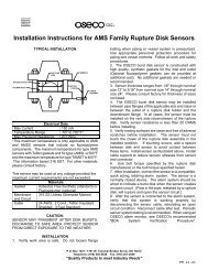
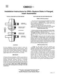
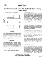
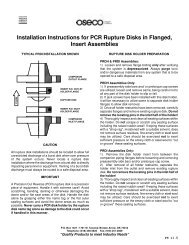
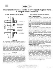
TYPICAL <strong>POSI</strong> INSTALLATION<br />
objects on top of the knife blades or holder. The knife<br />
blades must be kept very sharp and free of nicks and<br />
defects <strong>in</strong> order <strong>for</strong> the disk assembly to function<br />
properly.<br />
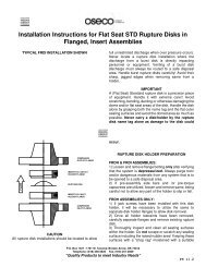
RUPTURE DISK HOLDER PREPARATION<br />
1) Loosen and remove flange bolt<strong>in</strong>g only after<br />
verify<strong>in</strong>g that the system is depressurized. Always<br />
purge toxic and/or dangerous materials to a safe<br />
disposal area from any system that is to be opened to<br />
a safe disposal area..<br />
2) Slip the holder <strong>in</strong>sert from between the companion<br />
pip<strong>in</strong>g flanges and place on a flat work surface. Verify<br />
that all holder restra<strong>in</strong>ts have been removed.<br />
Separate the holder <strong>in</strong>let from the outlet and remove<br />
the exist<strong>in</strong>g rupture disk assembly.<br />
CAUTION<br />
All rupture disk <strong>in</strong>stallations should be located to allow<br />
full unrestricted discharge of a burst disk when<br />
overpressure of the system occurs. Never locate a<br />
rupture disk assembly where the discharge from a<br />
burst disk can directly impact personnel or equipment.<br />
Vent<strong>in</strong>g of a burst disk discharge must always be<br />
routed to a safe disposal area. Handle burst rupture<br />
disks carefully! Avoid their sharp, jagged edges when<br />
remov<strong>in</strong>g same from holder. The knife blades <strong>in</strong> the<br />
POSS holder are extremely sharp. Handle holders<br />
very carefully to avoid <strong>in</strong>jury.<br />
The <strong><strong>POSI</strong>PRO</strong> rupture disk assembly is a dual act<strong>in</strong>g<br />
precision piece of equipment. Handle it with extreme<br />
care. Avoid scratch<strong>in</strong>g, bend<strong>in</strong>g, dent<strong>in</strong>g or damag<strong>in</strong>g<br />
the dome and/or flat seat areas of the metal disk<br />
membrane. Handle the disk by the flat outer annular<br />
seat<strong>in</strong>g surfaces and avoid the dome area as much<br />
as possible. Never carry a <strong><strong>POSI</strong>PRO</strong> disk/holder<br />
assembly by the name tag alone as damage to the<br />
disk could occur. Do not place tools or <strong>for</strong>eign<br />
3) Thoroughly <strong>in</strong>spect and clean all seat<strong>in</strong>g surfaces<br />
of the disk holder. Do not scrape or scratch any<br />
seat<strong>in</strong>g surface! If wip<strong>in</strong>g these surfaces with a clean<br />
cloth and a suitable solvent does not remove surface<br />
residues, f<strong>in</strong>e emery cloth or steel wool may be<br />
utilized. Care should be exercised not to exert<br />
sufficient pressure on the emery cloth or steel wool to<br />
"cut or groove" these surfaces. When <strong>in</strong> doubt about<br />
the proper condition of these seal surfaces, contact<br />
OSECO <strong>for</strong> further <strong>in</strong>structions.<br />
4) Inspect knife blade po<strong>in</strong>ts and edges. Knife blade<br />
edges must be razor sharp and free of nicks or<br />
defects. Po<strong>in</strong>ts must be sharp and undamaged <strong>for</strong><br />
the disk assembly to work properly. Contact OSECO<br />
<strong>for</strong> repair or replacement of dull or damaged knife<br />
blades. Do not <strong>in</strong>stall the assembly if the blades are<br />
dull, nicked or damaged.<br />
RUPTURE DISK INSTALLATION<br />
1) Carefully unpack the rupture disk assembly. If the<br />
rupture disk assembly was packaged with a device<br />
marked "SHIPPING PROTECTOR - DO NOT USE",<br />
remove same now.<br />
P.O. Box 1327 / 1701 W. Tacoma/ Broken Arrow, OK 74012<br />
Telephone: (918) 258-5626 Fax: (918) 251-2809<br />
“Quality Products to meet Industry Needs”<br />
PS 11.14
<strong>Installation</strong> <strong>Instructions</strong> <strong>for</strong> <strong><strong>POSI</strong>PRO</strong> <strong>Rupture</strong> <strong>Disks</strong> <strong>in</strong> <strong>POSI</strong><br />
Holder<br />
2) Place the <strong>in</strong>sert <strong>POSI</strong> Inlet on a flat work surface<br />
with the p<strong>in</strong> holes up. Place the rupture disk assembly<br />
on the holder, carefully align<strong>in</strong>g the holes <strong>in</strong> the flange<br />
portion of the rupture disk assembly with the holes <strong>in</strong><br />
the <strong>POSI</strong> <strong>in</strong>let. Dome goes down <strong>in</strong>to the <strong>in</strong>let.<br />
3) Position the Insert <strong>POSI</strong> Outlet over the rupture<br />
disk assembly, carefully align<strong>in</strong>g the <strong>POSI</strong> <strong>in</strong>let<br />
alignment holes with the p<strong>in</strong>s <strong>in</strong> the <strong>POSI</strong> outlet.<br />
Then lower the <strong>POSI</strong> outlet until it engages the <strong>POSI</strong><br />
<strong>in</strong>let alignment holes and rests on the flat outer<br />
annular seat<strong>in</strong>g surface of the rupture disk assembly.<br />
If <strong>in</strong>terference is present, correct be<strong>for</strong>e cont<strong>in</strong>u<strong>in</strong>g.<br />
4) Install sidebars; however, cap screws should only<br />
be snug, not wrench tight.<br />
5) Check companion flanges and verify that seal<strong>in</strong>g<br />
surfaces are clean and free of corrosion and debris.<br />
<strong><strong>POSI</strong>PRO</strong> / <strong>POSI</strong> TORQUE TABLE<br />
DISK SIZE FITTING SIZE TORQUE<br />
VALUE<br />
IN. mm ANSI DIN FT LB N M<br />
3 80 150 - 40 54<br />
- - - 10/16 20 27<br />
4 100 150 10/16 30 41<br />
6 150 150 - 40 54<br />
- - - 10/16 42 57<br />
8 200 150 - 50 68<br />
- - - 10 52 70<br />
- - - 16 35 47<br />
10 250 150 - 70 85<br />
- - - 10 63 85<br />
- - - 16 76 103<br />
6) Position the <strong>POSI</strong>/<strong><strong>POSI</strong>PRO</strong> assembly with<strong>in</strong> the<br />
bolt circle of companion pip<strong>in</strong>g flanges. The convex<br />
side (dome) of the rupture disk assembly should face<br />
the process or possible vacuum source. Re<strong>in</strong>stall<br />
studs, nuts and suitable gaskets. Studs and nuts<br />
should be lightly oiled and free runn<strong>in</strong>g.<br />
7) Tighten each nut f<strong>in</strong>ger tight, then us<strong>in</strong>g a<br />
calibrated torque wrench, tighten each nut <strong>in</strong> a<br />
cross pattern. Use <strong>in</strong>crements of 20% of the<br />
recommended torque value listed <strong>in</strong> the adjacent<br />
table. Do not use torque values <strong>in</strong> excess of those<br />
shown <strong>in</strong> the table as this may damage the disk or<br />
the bite seal on the holder<br />
P.O. Box 1327 / 1701 W. Tacoma/ Broken Arrow, OK 74012<br />
Telephone: (918) 258-5626 Fax: (918) 251-2809<br />
“Quality Products to meet Industry Needs”<br />
PS 11.14