Installation Instructions for AMS Family Rupture Disk Sensors - Oseco
Installation Instructions for AMS Family Rupture Disk Sensors - Oseco
Installation Instructions for AMS Family Rupture Disk Sensors - Oseco

Create successful ePaper yourself
Turn your PDF publications into a flip-book with our unique Google optimized e-Paper software.
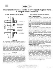
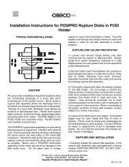
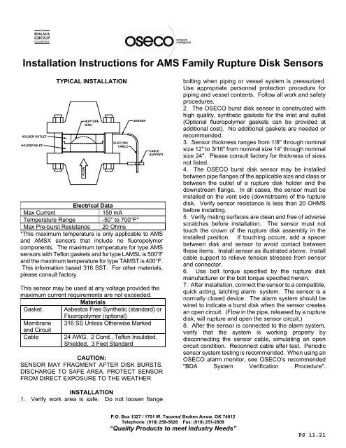
<strong>Installation</strong> <strong>Instructions</strong> <strong>for</strong> <strong>AMS</strong> <strong>Family</strong> <strong>Rupture</strong> <strong>Disk</strong> <strong>Sensors</strong>HOLDER OUTLETHOLDER INLETTYPICAL INSTALLATIONFLOWRUPTUREDISKELECTRICCABLESENSORCABLESUPPORTElectrical DataMax Current150 mATemperature Range -50° to 700°F*Max Pre-burst Resistance 20 Ohms*This maximum temperature is only applicable to <strong>AMS</strong>and <strong>AMS</strong>X sensors that include no fluoropolymercomponents. The maximum temperature <strong>for</strong> type <strong>AMS</strong>sensors with Teflon gaskets and <strong>for</strong> type L<strong>AMS</strong>L is 500°Fand the maximum temperature <strong>for</strong> type T<strong>AMS</strong>T is 400°F.This in<strong>for</strong>mation based 316 SST. For other materials,please consult factory.This sensor may be used at any voltage provided themaximum current requirements are not exceeded.MaterialsGasket Asbestos Free Synthetic (standard) orFluoropolymer (optional)Membrane 316 SS Unless Otherwise Markedand CircuitCable24 AWG, 2 Cond., Teflon Insulated,Shielded, 3 Feet StandardCAUTION:SENSOR MAY FRAGMENT AFTER DISK BURSTS.DISCHARGE TO SAFE AREA. PROTECT SENSORFROM DIRECT EXPOSURE TO THE WEATHERbolting when piping or vessel system is pressurized.Use appropriate personnel protection procedure <strong>for</strong>piping and vessel contents. Follow all work and safetyprocedures.2. The OSECO burst disk sensor is constructed withhigh quality, synthetic gaskets <strong>for</strong> the inlet and outlet(Optional fluoropolymer gaskets can be provided atadditional cost). No additional gaskets are needed orrecommended.3. Sensor thickness ranges from 1/8" through nominalsize 12" to 3/16" from nominal size 14” through nominalsize 24". Please consult factory <strong>for</strong> thickness of sizesnot listed.4. The OSECO burst disk sensor may be installedbetween pipe flanges of the applicable size and class orbetween the outlet of a rupture disk holder and thedownstream flange. In all cases, the sensor must beinstalled on the vent side (downstream) of the rupturedisk. Verify sensor resistance is less than 20 OHMSbe<strong>for</strong>e installing.5. Verify mating surfaces are clean and free of adversescratches be<strong>for</strong>e installation. The sensor must nottouch the crown of the rupture disk assembly in theinstalled position. If touching occurs, add a spacerbetween disk and sensor to avoid contact betweenthese items. Install sensor as illustrated above. Installcable support to relieve tension stresses from sensorand connector.6. Use bolt torque specified by the rupture diskmanufacturer or the bolt torque specified herein.7. After installation, connect the sensor to a compatible,quick acting, latching alarm system. The sensor is anormally closed device. The alarm system should bewired to indicate a burst disk when the sensor createsan open circuit. (Flow in the pipe, released by a rupturedisk, will rupture and open the sensor circuit.)8. After the sensor is connected to the alarm system,verify that the system is working properly bydisconnecting the sensor cable, simulating an opencircuit condition. Reconnect cable after test. Periodicsensor system testing is recommended. When using anOSECO alarm monitor, see OSECO's recommended"BDA System Verification Procedure".INSTALLATION1. Verify work area is safe. Do not loosen flangeP.O. Box 1327 / 1701 W. Tacoma/ Broken Arrow, OK 74012Telephone: (918) 258-5626 Fax: (918) 251-2809“Quality Products to meet Industry Needs”PS 11.21
<strong>Installation</strong> <strong>Instructions</strong> <strong>for</strong> <strong>AMS</strong> <strong>Family</strong> <strong>Rupture</strong> <strong>Disk</strong> <strong>Sensors</strong>FLANGE BOLT TORQUE DATA (FT-LBS)SIZE ANSI 150 ANSI 300 ANSI 600 ANSI 900 ANSI 15001 33 40 40 55 551-1/2 45 98 98 131 1312 88 68 68 94 942-1/2 88 95 95 124 1243 88 141 141 164 2044 88 153 234 290 3176 153 153 278 309 3698 153 243 419 - - - -10 243 339 413 - - - -12 243 508 446 - - - -14 361 444 - - - - - -16 361 497 - - - - - -18 523 561 - - - - - -20 523 629 - - - - - -24 726 971 - - - - - -Notes:1. Use torque specified by disk manufacturer when sensor is installed between a rupture disk holder and aflange.2. Use torque values from table above when sensor is installed between companion piping flanges withKlingersil C-4401 gasket. Contact the factory <strong>for</strong> required values with Teflon gaskets.3. Use pressure and temperature limitations <strong>for</strong> Klingersil C-4401 gasket material made by Thermoseal Inc.,Sidney OH.4. Torques have been limited to 40,000 psi bolt stress <strong>for</strong> B7M studs.5. Torque values are based on nuts and studs lightly lubricated and maintained in a "free-running" condition.Required Burst PressuresSize (in.)Minimum BurstMinimum BurstSize (in.)Pressure (psig)Pressure (psig)1.0 5.0 10.0 1.01.5 5.0 12.0 1.02.0 5.0 14.0 1.03.0 3.0 16.0 0.754.0 2.0 18.0 0.756.0 4.0 20.0 0.758.0 1.0 24.0 0.75P.O. Box 1327 / 1701 W. Tacoma/ Broken Arrow, OK 74012Telephone: (918) 258-5626 Fax: (918) 251-2809“Quality Products to meet Industry Needs”PS 11.21